Enterprise Modernization Sandbox for IBM i Lab Exercise Workbook€¦ · IBM Software IBM...
70
Enterprise Modernization Sandbox for IBM i Lab Exercise Workbook Rational Developer for i Lab 06 – Application Diagram Viewer This lab is an introduction to the Application Diagram Viewer Version 4, March 2016 The most up to date version of this document can be found on Rational Developer for i - Hands-On Labs at http://ibm.biz/rdi_labs. IBM Software ©2014 IBM Corporation
Transcript of Enterprise Modernization Sandbox for IBM i Lab Exercise Workbook€¦ · IBM Software IBM...
IBM Software
IBM Enterprise Modernization Sandbox – RDi Lab 06 – Application Diagram Viewer Page 1
Enterprise Modernization Sandbox for IBM i Lab Exercise Workbook
Rational Developer for i
Lab 06 – Application Diagram Viewer
This lab is an introduction to the Application Diagram Viewer
Version 4, March 2016
The most up to date version of this document can be found on Rational Developer for i -
Hands-On Labs at http://ibm.biz/rdi_labs.
IBM Software
©2014 IBM Corporation

IBM Software
Page 2 IBM Enterprise Modernization Sandbox – RDi Lab 06 – Application Diagram Viewer
© Copyright International Business Machines Corporation, 2016. All rights reserved.
US Government Users Restricted Rights - Use, duplication or disclosure restricted by GSA ADP Schedule Contract with IBM Corp.
IBM Software
IBM Enterprise Modernization Sandbox – RDi Lab 06 – Application Diagram Viewer Page 3
LAB 06 – INTRODUCTION TO THE APPLICATION DIAGRAM VIEWER .............................................................. 4 Overview ................................................................................................................................................... 4
Learning objectives ................................................................................................................................. 4 Skill level and prerequisites ................................................................................................................... 4
Conventions used in this workbook ...................................................................................................... 5 Client System requirements ................................................................................................................... 5
Host System requirements ..................................................................................................................... 5 1 INTRODUCTION ....................................................................................................................................... 6 2 THE APPLICATION DIAGRAMMING ENVIRONMENT .................................................................................. 7
3 CREATING A SOURCE CALL DIAGRAM .................................................................................................... 8 3.1 Starting the workbench ................................................................................................................ 8
3.2 Creating an application diagram ................................................................................................. 8
3.3 Changing the library list ............................................................................................................... 9
3.4 Selecting source members and creating the diagram .......................................................... 10
3.5 Basic navigation in an application diagram ............................................................................ 13 4 WORKING WITH AN APPLICATION DIAGRAM .......................................................................................... 18
4.1 Navigating an application diagram using the Outline view................................................... 18 4.2 Opening a source file from an application diagram ............................................................... 22
4.3 Working with the Properties view ............................................................................................. 27 5 CREATING A PROGRAM STRUCTURE DIAGRAM .................................................................................... 30
5.1 Creating a filter in RSE .............................................................................................................. 30 5.2 Creating the diagram .................................................................................................................. 31 5.3 Working with the diagram .......................................................................................................... 33
5.4 Working with properties ............................................................................................................. 33
5.5 Working with diagram views ..................................................................................................... 36
6 CHANGING APPLICATION DIAGRAMS .................................................................................................... 40
6.1 Annotating an application diagram ........................................................................................... 40
6.2 Creating a stand-alone note ...................................................................................................... 45
6.3 Creating text ................................................................................................................................ 46 6.4 Changing properties for objects in diagrams .......................................................................... 46
6.5 Changing an application diagram’s layout .............................................................................. 48 7 STORING AN APPLICATION DIAGRAM FOR FUTURE USE ....................................................................... 53
7.1 Saving an application diagram for re-use ............................................................................... 53 7.2 Saving a diagram as a text file ................................................................................................. 58
7.3 Saving a diagram or parts of a diagram as an image file ..................................................... 60 8 PRINTING AN APPLICATION DIAGRAM ................................................................................................... 64 CONGRATULATIONS! .................................................................................................................................... 66
APPENDIX A NOTICES ............................................................................................................................. 67 APPENDIX B TRADEMARKS AND COPYRIGHTS ........................................................................................ 69

IBM Software
Page 4 IBM Enterprise Modernization Sandbox – RDi Lab 06 – Application Diagram Viewer
Lab 06 – Introduction to the Application Diagram Viewer
Overview
This tutorial teaches you how to use the Application Diagram Viewer to visualize the structure and flow
of native IBM i® applications. Using sample IBM i programs that are provided with the tutorial, you will
work with the Source Call Diagram and Program Structure Diagram views to understand the structure
of those programs. Then you will navigate through the application diagram to edit the source code,
change settings, and add notes to a diagram.
Learning objectives
1. Create an application diagram for selected IBM i program objects or source members.
2. Use the Outline view to navigate the diagram.
3. View and edit the source members associated with nodes in the application diagram
4. Annotate the diagram
5. Change an application diagram’s default settings
6. Save and print the application diagram
Skill level and prerequisites
Introductory.
Important!
You should complete RDi Lab01 ‘Getting started’ before you work on this lab. Lab01
contains the following information and instructions:
Which IBM i server to connect to
Which User ID to use
How to start RDi, create a connection and connect
How to setup the correct library list for this lab
Knowledge of basic Microsoft Windows operations such as working with the desktop, mouse operations
such as opening folders and drag-and-drop is assumed. It will also be helpful if you understand DDS and
ILE RPG.
IBM Software
IBM Enterprise Modernization Sandbox – RDi Lab 06 – Application Diagram Viewer Page 5
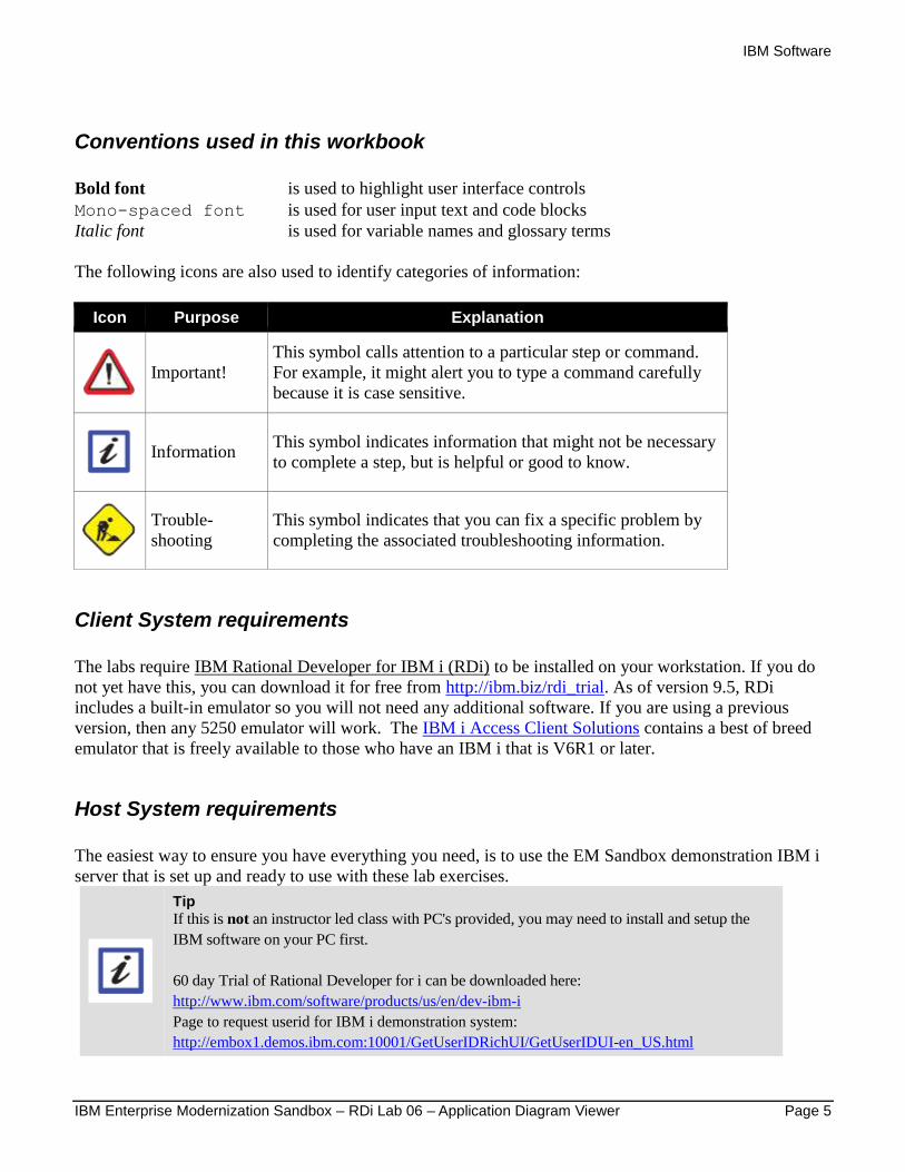
Conventions used in this workbook
Bold font is used to highlight user interface controls
Mono-spaced font is used for user input text and code blocks
Italic font is used for variable names and glossary terms
The following icons are also used to identify categories of information:
Icon Purpose Explanation
Important!
This symbol calls attention to a particular step or command.
For example, it might alert you to type a command carefully
because it is case sensitive.
Information This symbol indicates information that might not be necessary
to complete a step, but is helpful or good to know.
Trouble-
shooting
This symbol indicates that you can fix a specific problem by
completing the associated troubleshooting information.
Client System requirements
The labs require IBM Rational Developer for IBM i (RDi) to be installed on your workstation. If you do
not yet have this, you can download it for free from http://ibm.biz/rdi_trial. As of version 9.5, RDi
includes a built-in emulator so you will not need any additional software. If you are using a previous
version, then any 5250 emulator will work. The IBM i Access Client Solutions contains a best of breed
emulator that is freely available to those who have an IBM i that is V6R1 or later.
Host System requirements
The easiest way to ensure you have everything you need, is to use the EM Sandbox demonstration IBM i
server that is set up and ready to use with these lab exercises.
Tip If this is not an instructor led class with PC's provided, you may need to install and setup the
IBM software on your PC first.
60 day Trial of Rational Developer for i can be downloaded here:
http://www.ibm.com/software/products/us/en/dev-ibm-i
Page to request userid for IBM i demonstration system:
http://embox1.demos.ibm.com:10001/GetUserIDRichUI/GetUserIDUI-en_US.html
IBM Software
Page 6 IBM Enterprise Modernization Sandbox – RDi Lab 06 – Application Diagram Viewer
1 Introduction
In this tutorial, you learn how to use the Application Diagram Viewer with IBM i application resources
and make changes to the generated diagram.
When you need to change an existing IBM i native application, you can gain a better understanding of the
connections between resources by viewing a graphical representation rather than looking at source code.
The Application Diagram Viewer helps you navigate easily among related IBM i resources and links to
those resources to allow viewing and editing in the Remote Systems LPEX editor. This includes a
diagram to display the call graph for CL, ILE RPG and ILE COBOL resources and a diagram to show the
binding relationships for program and service program objects.
An application diagram is made up of nodes and connections. Nodes represent different resources in your
application; connections represent the relationship between those artifacts.
You will create an application diagram, for an existing Order Entry application, using the default
diagram layout. You will learn how to change those default settings.
You will use the Outline view to navigate through the generated application diagram and view source
code by launching the Remote Systems LPEX editor from the diagram. You will change the application
diagram’s visual style and document the diagram by adding notes to the diagram. To keep those changes,
you will save the application diagram in several file types. Saving to a workspace file allows you to
reopen the application diagram at a later time.
IBM Software
IBM Enterprise Modernization Sandbox – RDi Lab 06 – Application Diagram Viewer Page 7
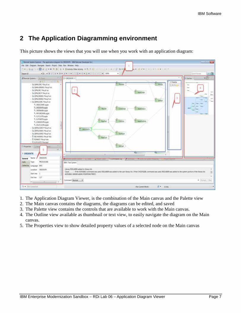
2 The Application Diagramming environment
This picture shows the views that you will use when you work with an application diagram:
1. The Application Diagram Viewer, is the combination of the Main canvas and the Palette view
2. The Main canvas contains the diagrams, the diagrams can be edited, and saved
3. The Palette view contains the controls that are available to work with the Main canvas.
4. The Outline view available as thumbnail or text view, to easily navigate the diagram on the Main
canvas.
5. The Properties view to show detailed property values of a selected node on the Main canvas
IBM Software
Page 8 IBM Enterprise Modernization Sandbox – RDi Lab 06 – Application Diagram Viewer
3 Creating a Source Call diagram
You will learn first, how to create a Source Call diagram that shows how subroutines, procedures and
external programs are connected to each other in a given application.
3.1 Starting the workbench
Please use Lab01 'Getting started with RSE' for instructions on:
1. How to start the workbench.
2. How to get connected to an IBM i server.
3. Which server to use and which User ID to use, for IBM supplied IBM i systems.
After you have created a connection, go ahead to the next section.
3.2 Creating an application diagram
There are two ways to create an application diagram:
1) In the Remote Systems LPEX editor, when editing source code.
If you are interested in analyzing one source member as you are working with it, then use this option.
2) In the Remote Systems Explorer, when you need to analyze multiple source members in one diagram.
Launching from the Remote Systems Explorer perspective allows multiple selections of select RSE
resources of the same type:
1) ILE RPG and ILE COBOL source members, IFS files and local files.
2) IFS folders. (All ILE RPG and ILE COBOL source files in the folder are included.)
3) Local folders. (All ILE RPG and ILE COBOL source files in the folder are included.)
4) Member filters.
5) Program and service program objects.
6) Object filters.
The Application diagram tool uses the program Verifier, which is the frontend of the IBM i ILE
compilers. The Verifier extracts the information needed for the diagram. If the Verifier fails because of
semantic or syntax errors, the Application Diagram can't be created. To create an Application Diagram
you will need a source member that will compile error free with all the external references needed. This
means you need to setup the library list for the RSE job according to the program’s environment needs.
To accomplish this for this lab you need to add the application library WFLABXX to the library list of
the RSE job.
You will add another library to the connection's library list for these exercises.
IBM Software
IBM Enterprise Modernization Sandbox – RDi Lab 06 – Application Diagram Viewer Page 9
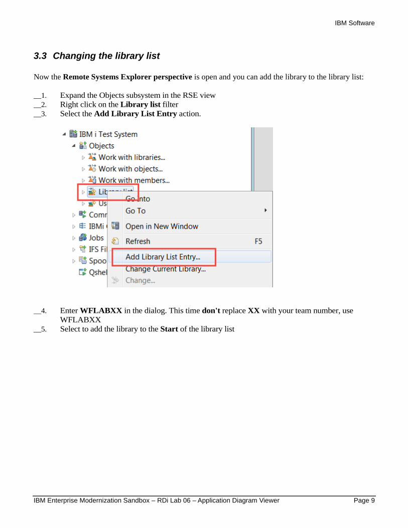
3.3 Changing the library list
Now the Remote Systems Explorer perspective is open and you can add the library to the library list:
__1. Expand the Objects subsystem in the RSE view
__2. Right click on the Library list filter
__3. Select the Add Library List Entry action.
__4. Enter WFLABXX in the dialog. This time don't replace XX with your team number, use
WFLABXX
__5. Select to add the library to the Start of the library list
IBM Software
Page 10 IBM Enterprise Modernization Sandbox – RDi Lab 06 – Application Diagram Viewer
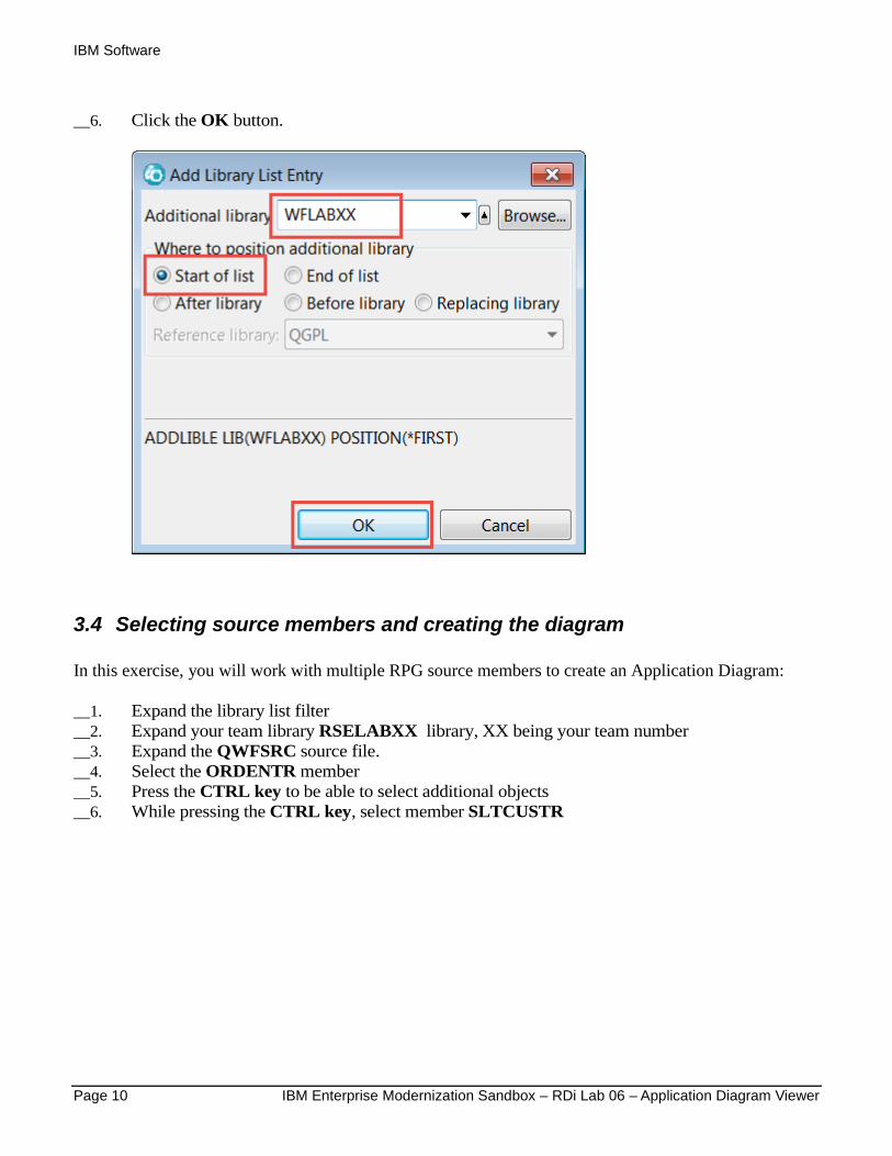
__6. Click the OK button.
3.4 Selecting source members and creating the diagram
In this exercise, you will work with multiple RPG source members to create an Application Diagram:
__1. Expand the library list filter
__2. Expand your team library RSELABXX library, XX being your team number
__3. Expand the QWFSRC source file.
__4. Select the ORDENTR member
__5. Press the CTRL key to be able to select additional objects
__6. While pressing the CTRL key, select member SLTCUSTR

IBM Software
IBM Enterprise Modernization Sandbox – RDi Lab 06 – Application Diagram Viewer Page 11
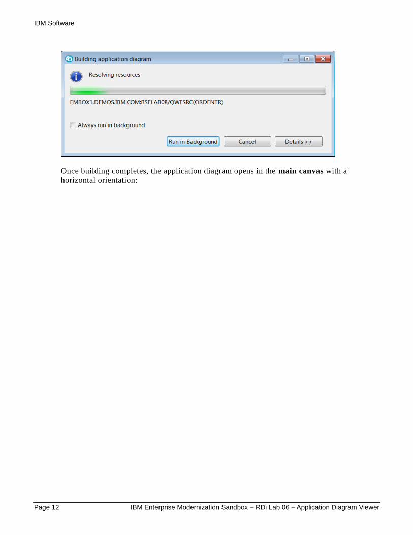
__7. Right-click and select the Visualize Application Diagram action.
A progress bar shows that the diagram is being built:
IBM Software
Page 12 IBM Enterprise Modernization Sandbox – RDi Lab 06 – Application Diagram Viewer
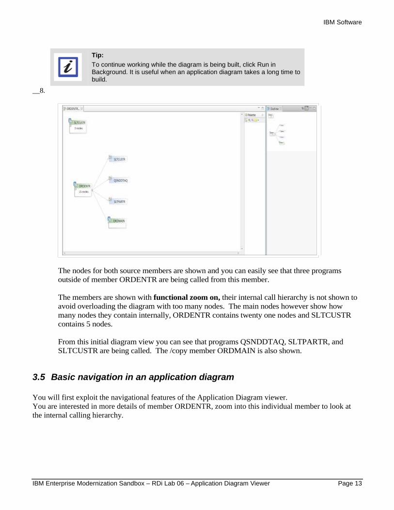
Once building completes, the application diagram opens in the main canvas with a
horizontal orientation:
IBM Software
IBM Enterprise Modernization Sandbox – RDi Lab 06 – Application Diagram Viewer Page 13
Tip:
To continue working while the diagram is being built, click Run in Background. It is useful when an application diagram takes a long time to build.
__8.
The nodes for both source members are shown and you can easily see that three programs
outside of member ORDENTR are being called from this member.
The members are shown with functional zoom on, their internal call hierarchy is not shown to
avoid overloading the diagram with too many nodes. The main nodes however show how
many nodes they contain internally, ORDENTR contains twenty one nodes and SLTCUSTR
contains 5 nodes.
From this initial diagram view you can see that programs QSNDDTAQ, SLTPARTR, and
SLTCUSTR are being called. The /copy member ORDMAIN is also shown.
3.5 Basic navigation in an application diagram
You will first exploit the navigational features of the Application Diagram viewer.
You are interested in more details of member ORDENTR, zoom into this individual member to look at
the internal calling hierarchy.
IBM Software
Page 14 IBM Enterprise Modernization Sandbox – RDi Lab 06 – Application Diagram Viewer
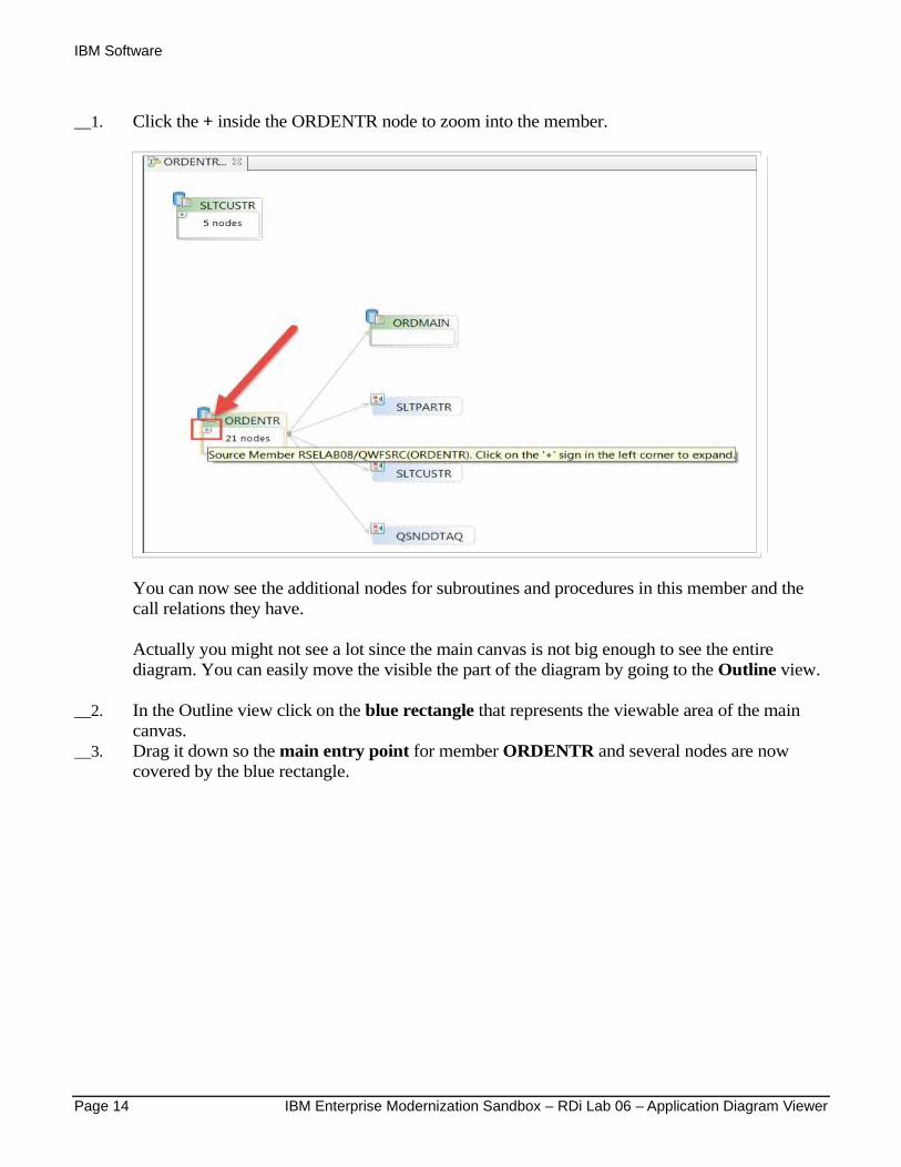
__1. Click the + inside the ORDENTR node to zoom into the member.
You can now see the additional nodes for subroutines and procedures in this member and the
call relations they have.
Actually you might not see a lot since the main canvas is not big enough to see the entire
diagram. You can easily move the visible the part of the diagram by going to the Outline view.
__2. In the Outline view click on the blue rectangle that represents the viewable area of the main
canvas.
__3. Drag it down so the main entry point for member ORDENTR and several nodes are now
covered by the blue rectangle.

IBM Software
IBM Enterprise Modernization Sandbox – RDi Lab 06 – Application Diagram Viewer Page 15
__4. Also hide the Palette view by clicking on the hide button on top of the Palette view.
If you want to the get the Palette view back you can use the hide toggle button to un-hide it.
If you still need more visible space for the diagram, you can maximize the Main canvas.

IBM Software
Page 16 IBM Enterprise Modernization Sandbox – RDi Lab 06 – Application Diagram Viewer
__5. Double click on the Main Canvas tab.
This gives you a nice area on the Main canvas to work with the diagram.
IBM Software
IBM Enterprise Modernization Sandbox – RDi Lab 06 – Application Diagram Viewer Page 17
Note:
Double clicking on the Main canvas tab will restore the view to its original size.
Note:
If you need a specific view that is hidden because of the maximized Main canvas. You can use the fast view buttons on the sidebars of the workbench to restore individual views. If you hover over a fast view button yon see text that shows the view name.
Now that you have launched the application diagram, you are ready to work with it.
IBM Software
Page 18 IBM Enterprise Modernization Sandbox – RDi Lab 06 – Application Diagram Viewer
4 Working with an application diagram
In this module, you will learn how to navigate within an application diagram by using the Outline view.
4.1 Navigating an application diagram using the Outline view
You have already used the Outline view to move the highlighted rectangle to view different parts of the
diagram, but there is more to the Outline view.
The default view for the Outline view is the Overview or Thumbnail view, this is the view you used in
the previous exercise. There is also a Text view available that shows the diagram content in a tree view.
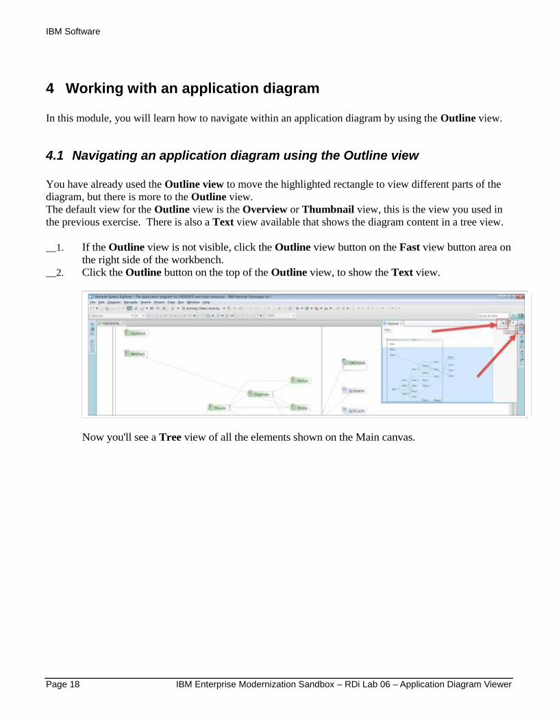
__1. If the Outline view is not visible, click the Outline view button on the Fast view button area on
the right side of the workbench.
__2. Click the Outline button on the top of the Outline view, to show the Text view.
Now you'll see a Tree view of all the elements shown on the Main canvas.
IBM Software
IBM Enterprise Modernization Sandbox – RDi Lab 06 – Application Diagram Viewer Page 19
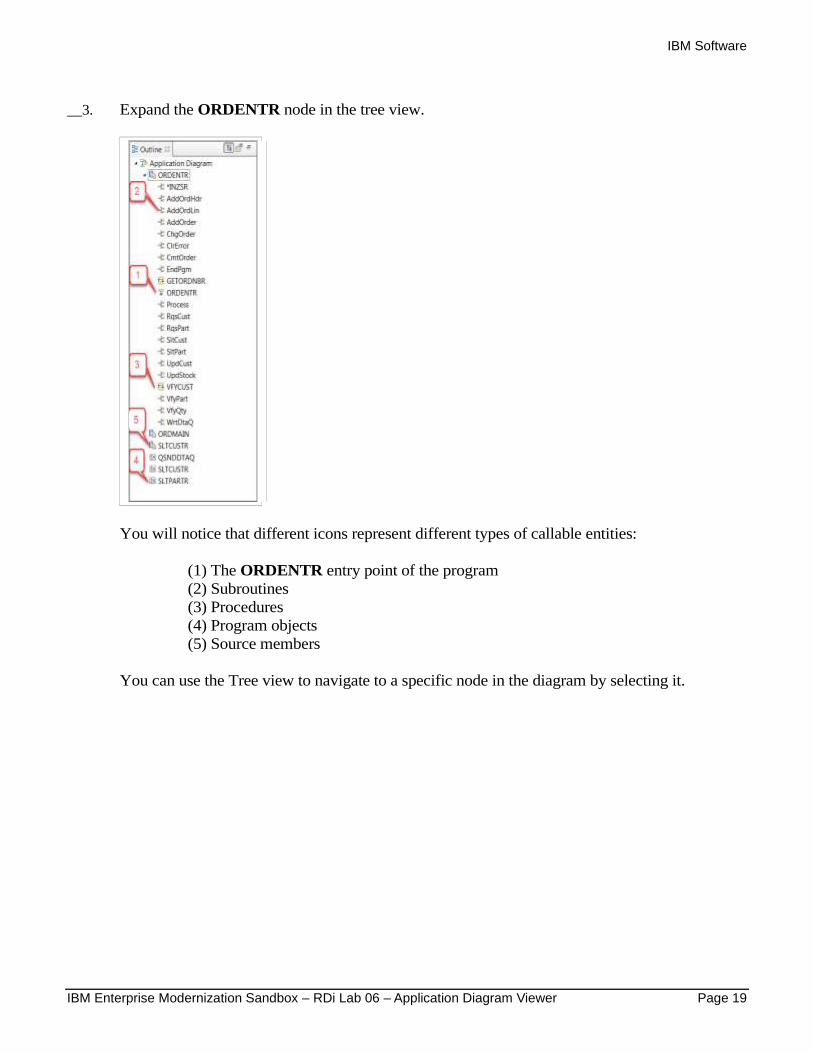
__3. Expand the ORDENTR node in the tree view.
You will notice that different icons represent different types of callable entities:
(1) The ORDENTR entry point of the program
(2) Subroutines
(3) Procedures
(4) Program objects
(5) Source members
You can use the Tree view to navigate to a specific node in the diagram by selecting it.
IBM Software
Page 20 IBM Enterprise Modernization Sandbox – RDi Lab 06 – Application Diagram Viewer
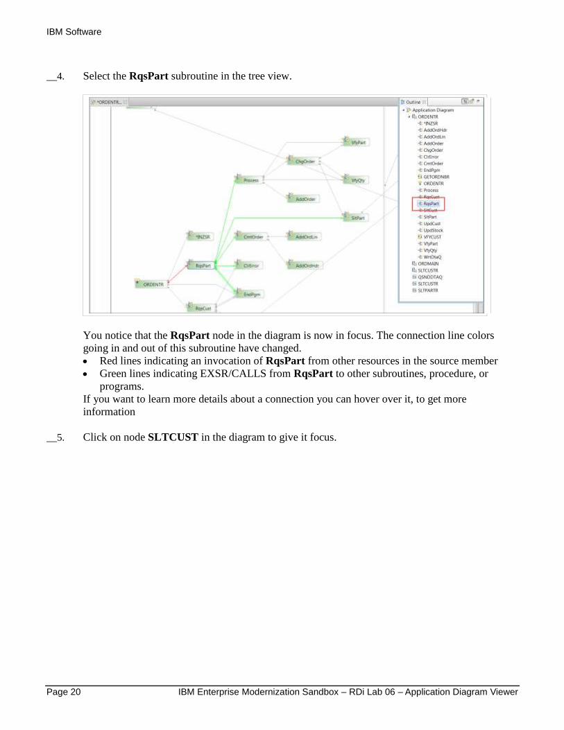
__4. Select the RqsPart subroutine in the tree view.
You notice that the RqsPart node in the diagram is now in focus. The connection line colors
going in and out of this subroutine have changed.
Red lines indicating an invocation of RqsPart from other resources in the source member
Green lines indicating EXSR/CALLS from RqsPart to other subroutines, procedure, or
programs.
If you want to learn more details about a connection you can hover over it, to get more
information
__5. Click on node SLTCUST in the diagram to give it focus.
IBM Software
IBM Enterprise Modernization Sandbox – RDi Lab 06 – Application Diagram Viewer Page 21
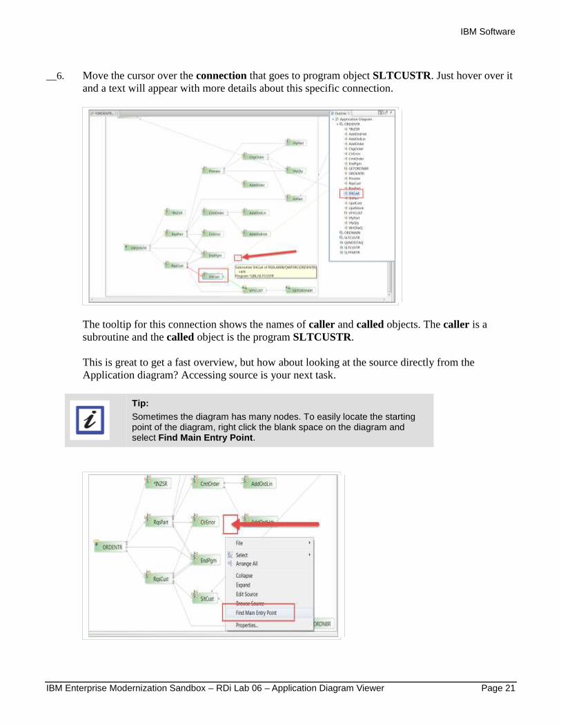
__6. Move the cursor over the connection that goes to program object SLTCUSTR. Just hover over it
and a text will appear with more details about this specific connection.
The tooltip for this connection shows the names of caller and called objects. The caller is a
subroutine and the called object is the program SLTCUSTR.
This is great to get a fast overview, but how about looking at the source directly from the
Application diagram? Accessing source is your next task.
Tip:
Sometimes the diagram has many nodes. To easily locate the starting point of the diagram, right click the blank space on the diagram and select Find Main Entry Point.
IBM Software
Page 22 IBM Enterprise Modernization Sandbox – RDi Lab 06 – Application Diagram Viewer
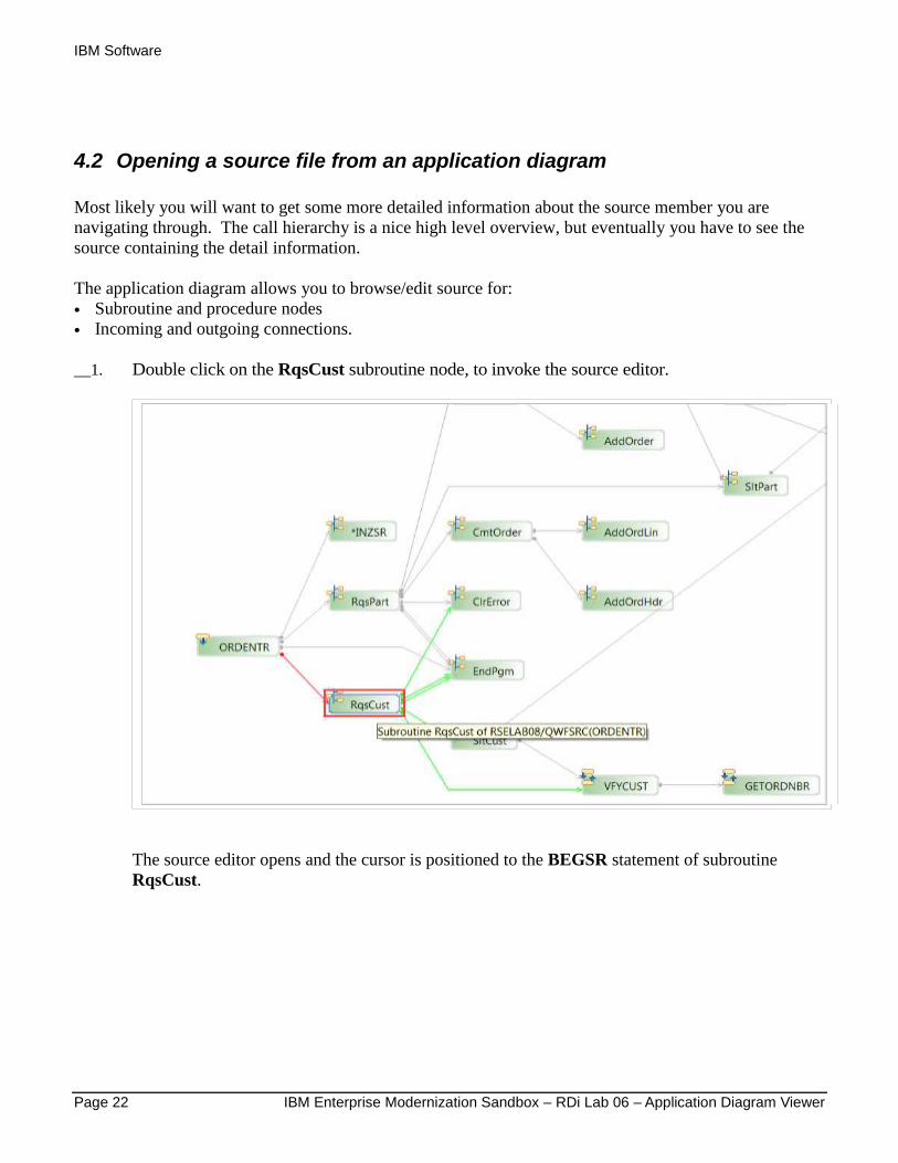
4.2 Opening a source file from an application diagram
Most likely you will want to get some more detailed information about the source member you are
navigating through. The call hierarchy is a nice high level overview, but eventually you have to see the
source containing the detail information.
The application diagram allows you to browse/edit source for:
• Subroutine and procedure nodes
• Incoming and outgoing connections.
__1. Double click on the RqsCust subroutine node, to invoke the source editor.
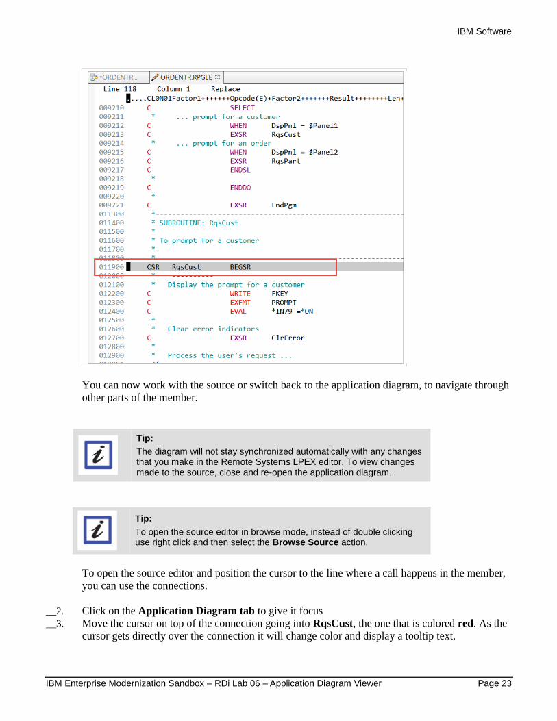
The source editor opens and the cursor is positioned to the BEGSR statement of subroutine
RqsCust.
IBM Software
IBM Enterprise Modernization Sandbox – RDi Lab 06 – Application Diagram Viewer Page 23
You can now work with the source or switch back to the application diagram, to navigate through
other parts of the member.
Tip:
The diagram will not stay synchronized automatically with any changes that you make in the Remote Systems LPEX editor. To view changes made to the source, close and re-open the application diagram.
Tip:
To open the source editor in browse mode, instead of double clicking use right click and then select the Browse Source action.
To open the source editor and position the cursor to the line where a call happens in the member,
you can use the connections.
__2. Click on the Application Diagram tab to give it focus
__3. Move the cursor on top of the connection going into RqsCust, the one that is colored red. As the
cursor gets directly over the connection it will change color and display a tooltip text.
IBM Software
Page 24 IBM Enterprise Modernization Sandbox – RDi Lab 06 – Application Diagram Viewer
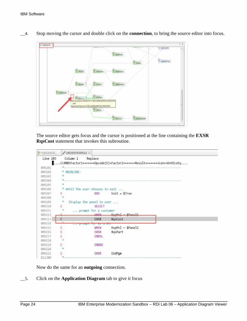
__4. Stop moving the cursor and double click on the connection, to bring the source editor into focus.
The source editor gets focus and the cursor is positioned at the line containing the EXSR
RqsCust statement that invokes this subroutine.
Now do the same for an outgoing connection.
__5. Click on the Application Diagram tab to give it focus

IBM Software
IBM Enterprise Modernization Sandbox – RDi Lab 06 – Application Diagram Viewer Page 25
__6. Move the cursor on top of the connection going out of RqsCust, the one that is colored green,
and invokes VFYCUST. As the cursor gets directly over the connection it will change color and
display a tooltip text.
__7. Stop moving the cursor and double click on the connection, to bring the source editor into focus.
Again the cursor will be positioned at the statement containing the selected invocation.
This works great for connections inside of the source member that invoke subroutines or
procedures located in the same source, but how about calls to outside programs? Application
Diagram doesn't support direct drill down to outside members, but remember you selected two
members to be shown in this diagram.
Now you will work with the second member.
__8. Click on the Application Diagram tab to give it focus
__9. Click the SltCust subroutine node. It actually has a connection to program SLTCUSTR outside
of this member.
To see the source of program SLTCUSTR you need to navigate to the source member, the
second member you selected to be added to this application diagram.
__10. To locate it on the Main canvas, move up to the top of the diagram, or use the outline view to
navigate there.
__11. Click on the + inside the node of SLTCUSTR to expand it and see its detailed call hierarchy.
IBM Software
Page 26 IBM Enterprise Modernization Sandbox – RDi Lab 06 – Application Diagram Viewer
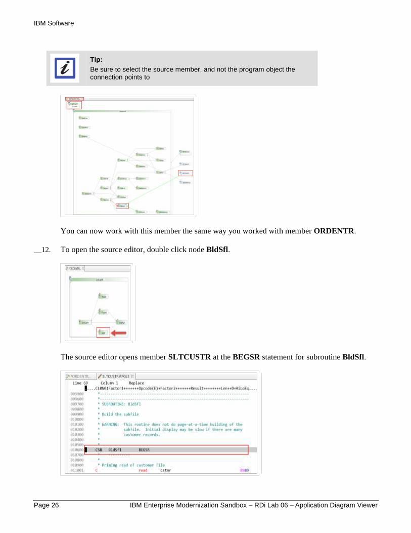
Tip:
Be sure to select the source member, and not the program object the connection points to
You can now work with this member the same way you worked with member ORDENTR.
__12. To open the source editor, double click node BldSfl.
The source editor opens member SLTCUSTR at the BEGSR statement for subroutine BldSfl.
IBM Software
IBM Enterprise Modernization Sandbox – RDi Lab 06 – Application Diagram Viewer Page 27
You can see that drilling down through multiple source members is pretty easy by selecting them
up front as you create a diagram.
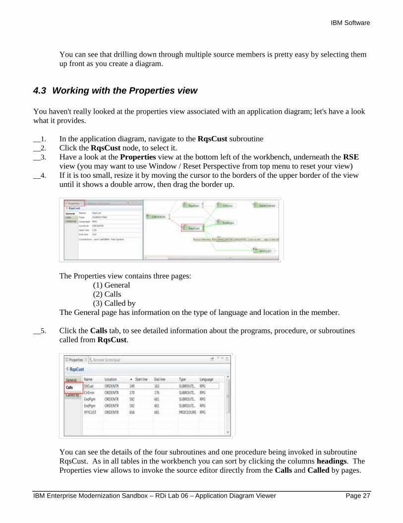
4.3 Working with the Properties view
You haven't really looked at the properties view associated with an application diagram; let's have a look
what it provides.
__1. In the application diagram, navigate to the RqsCust subroutine
__2. Click the RqsCust node, to select it.
__3. Have a look at the Properties view at the bottom left of the workbench, underneath the RSE
view (you may want to use Window / Reset Perspective from top menu to reset your view)
__4. If it is too small, resize it by moving the cursor to the borders of the upper border of the view
until it shows a double arrow, then drag the border up.
The Properties view contains three pages:
(1) General
(2) Calls
(3) Called by
The General page has information on the type of language and location in the member.
__5. Click the Calls tab, to see detailed information about the programs, procedure, or subroutines
called from RqsCust.
You can see the details of the four subroutines and one procedure being invoked in subroutine
RqsCust. As in all tables in the workbench you can sort by clicking the columns headings. The
Properties view allows to invoke the source editor directly from the Calls and Called by pages.
IBM Software
Page 28 IBM Enterprise Modernization Sandbox – RDi Lab 06 – Application Diagram Viewer
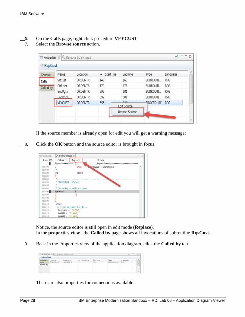
__6. On the Calls page, right click procedure VFYCUST
__7. Select the Browse source action.
If the source member is already open for edit you will get a warning message:
__8. Click the OK button and the source editor is brought in focus.
Notice, the source editor is still open in edit mode (Replace).
In the properties view , the Called by page shows all invocations of subroutine RqsCust.
__9. Back in the Properties view of the application diagram, click the Called by tab.
There are also properties for connections available.
IBM Software
IBM Enterprise Modernization Sandbox – RDi Lab 06 – Application Diagram Viewer Page 29
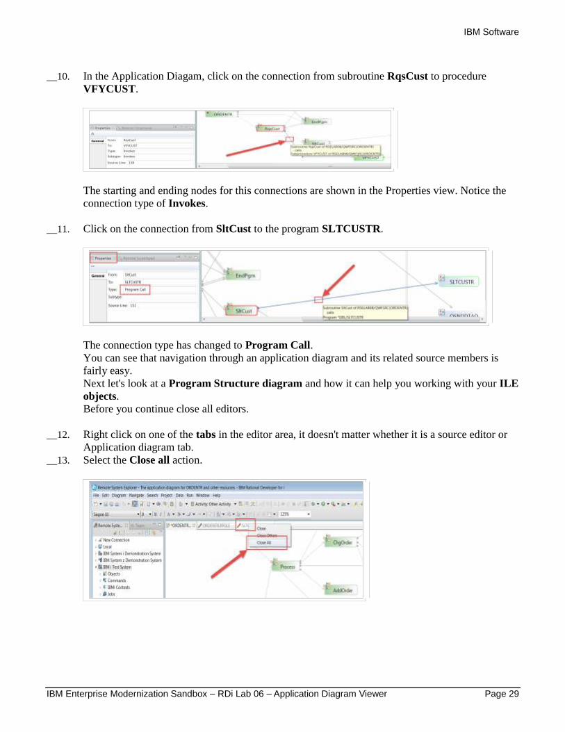
__10. In the Application Diagam, click on the connection from subroutine RqsCust to procedure
VFYCUST.
The starting and ending nodes for this connections are shown in the Properties view. Notice the
connection type of Invokes.
__11. Click on the connection from SltCust to the program SLTCUSTR.
The connection type has changed to Program Call.
You can see that navigation through an application diagram and its related source members is
fairly easy.
Next let's look at a Program Structure diagram and how it can help you working with your ILE
objects.
Before you continue close all editors.
__12. Right click on one of the tabs in the editor area, it doesn't matter whether it is a source editor or
Application diagram tab.
__13. Select the Close all action.
IBM Software
Page 30 IBM Enterprise Modernization Sandbox – RDi Lab 06 – Application Diagram Viewer
5 Creating a program structure diagram
The Program Structure diagram shows binding relations between IBM i program objects. Instead of
source members you select program objects to be added to the diagram.
Let's have a look at the WebFacing runtime and its binding relations.
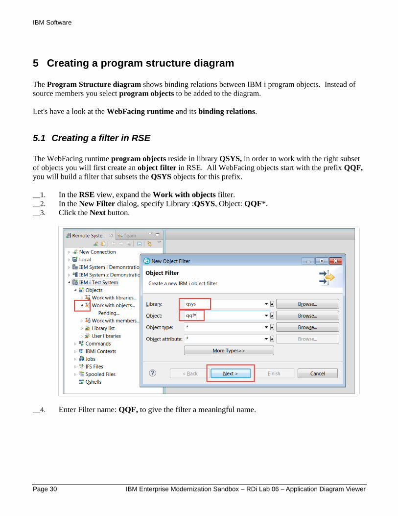
5.1 Creating a filter in RSE
The WebFacing runtime program objects reside in library QSYS, in order to work with the right subset
of objects you will first create an object filter in RSE. All WebFacing objects start with the prefix QQF,
you will build a filter that subsets the QSYS objects for this prefix.
__1. In the RSE view, expand the Work with objects filter.
__2. In the New Filter dialog, specify Library :QSYS, Object: QQF*.
__3. Click the Next button.
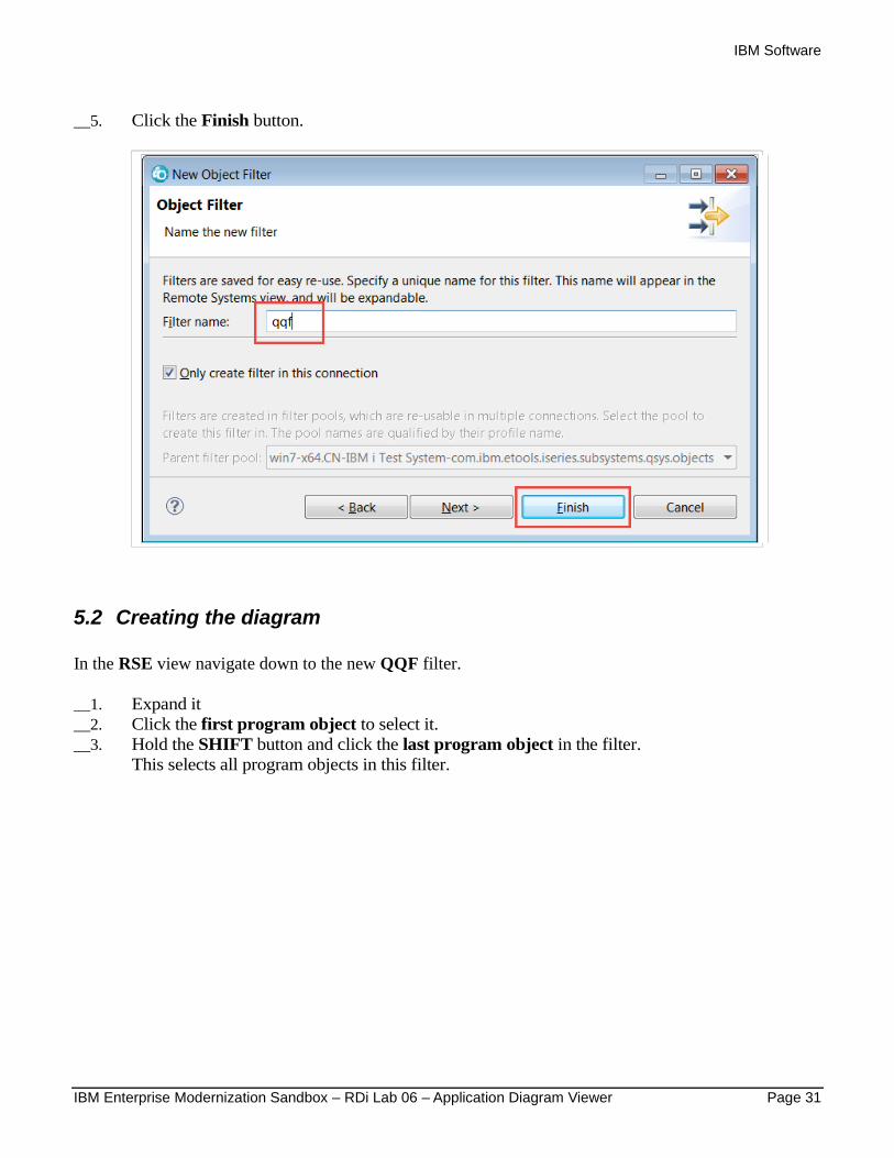
__4. Enter Filter name: QQF, to give the filter a meaningful name.
IBM Software
IBM Enterprise Modernization Sandbox – RDi Lab 06 – Application Diagram Viewer Page 31
__5. Click the Finish button.
5.2 Creating the diagram
In the RSE view navigate down to the new QQF filter.
__1. Expand it
__2. Click the first program object to select it.
__3. Hold the SHIFT button and click the last program object in the filter.
This selects all program objects in this filter.
IBM Software
Page 32 IBM Enterprise Modernization Sandbox – RDi Lab 06 – Application Diagram Viewer
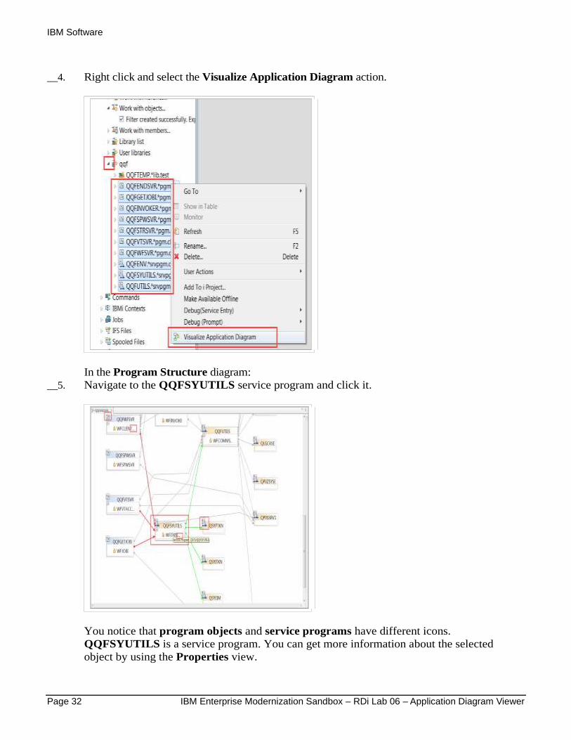
__4. Right click and select the Visualize Application Diagram action.
In the Program Structure diagram:
__5. Navigate to the QQFSYUTILS service program and click it.
You notice that program objects and service programs have different icons.
QQFSYUTILS is a service program. You can get more information about the selected
object by using the Properties view.
IBM Software
IBM Enterprise Modernization Sandbox – RDi Lab 06 – Application Diagram Viewer Page 33
It is easy to see that two programs bind this service program and it itself binds three
service programs. In this busy diagram the different coloring of connections comes in
handy. It makes it a lot easier to see incoming and outgoing connections of the selected node.
5.3 Working with the diagram
Notice that some programs and service programs have dots ... behind the module names. This indicates
they contain multiple modules.
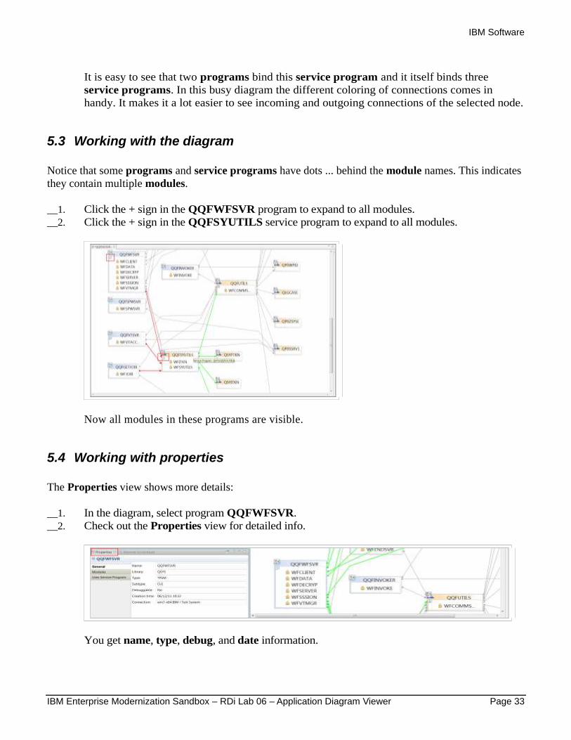
__1. Click the + sign in the QQFWFSVR program to expand to all modules.
__2. Click the + sign in the QQFSYUTILS service program to expand to all modules.
Now all modules in these programs are visible.
5.4 Working with properties
The Properties view shows more details:
__1. In the diagram, select program QQFWFSVR.
__2. Check out the Properties view for detailed info.
You get name, type, debug, and date information.
IBM Software
Page 34 IBM Enterprise Modernization Sandbox – RDi Lab 06 – Application Diagram Viewer
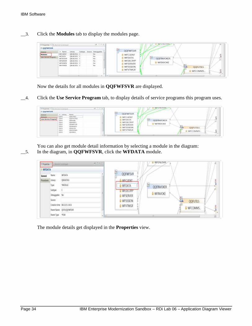
__3. Click the Modules tab to display the modules page.
Now the details for all modules in QQFWFSVR are displayed.
__4. Click the Use Service Program tab, to display details of service programs this program uses.
You can also get module detail information by selecting a module in the diagram:
__5. In the diagram, in QQFWFSVR, click the WFDATA module.
The module details get displayed in the Properties view.

IBM Software
IBM Enterprise Modernization Sandbox – RDi Lab 06 – Application Diagram Viewer Page 35
__6. In the Properties view, click the Procedures tab to display a list of procedures used in this
module.
These are the detailed program information, for service programs similar information is
available.
Let's look at the Exported Procedure view for service program QQFSYUTILS.
__7. In the diagram click the QQFSYUTILS service program to select it.
__8. In the Properties view, click the Exported Procedures tab.
This shows the exported procedures for this service program.
Note:
Sometimes, information in the Properties view is not available because not all resources were selected when the application diagram was launched. To view the missing information, you must close the diagram, select the missing resources in the Remote Systems view, and re-open the diagram.
IBM Software
Page 36 IBM Enterprise Modernization Sandbox – RDi Lab 06 – Application Diagram Viewer
5.5 Working with diagram views
The default for application diagrams is to show both views:
1. Source Call Diagram
2. Program structure diagram
You can change views and select to view just one of these views, by right clicking on the Main canvas of
the diagram and select the Switch views action.
You already created a default diagram showing both views when you went through the first Lab. The
Application diagram contained selected Source members and program objects that are called from the
source members. The nodes representing the called programs were shown with non solid border lines,
indicating that the detail information for these programs is not available. You could add detail program
information to these diagrams by selecting the source members and the program objects to be included
in the diagram. This gives you more detailed information about your application.
If you want to try this, go through the following steps or skip to the next module, Changing application
diagrams.
__1. Expand the Library list filter, by clicking the + sign
__2. Expand the WFLABXX library, by clicking the + sign. (if you have disconnected from the
host system since the start of this Lab, you will need to addlible WFLABXX again)
__3. Expand the QRPGLESRC source file.
__4. Select the ORDENTR member
__5. Press the CTRL key to be able to select additional objects
__6. While pressing the CTRL key, select member SLTCUSTR
__7. Scroll up in library WFLABXX to the section that shows program objects,
__8. While pressing the CTRL key, select program object SLTCUSTR
__9. While pressing the CTRL key, select program object SLTPARTR
IBM Software
IBM Enterprise Modernization Sandbox – RDi Lab 06 – Application Diagram Viewer Page 37
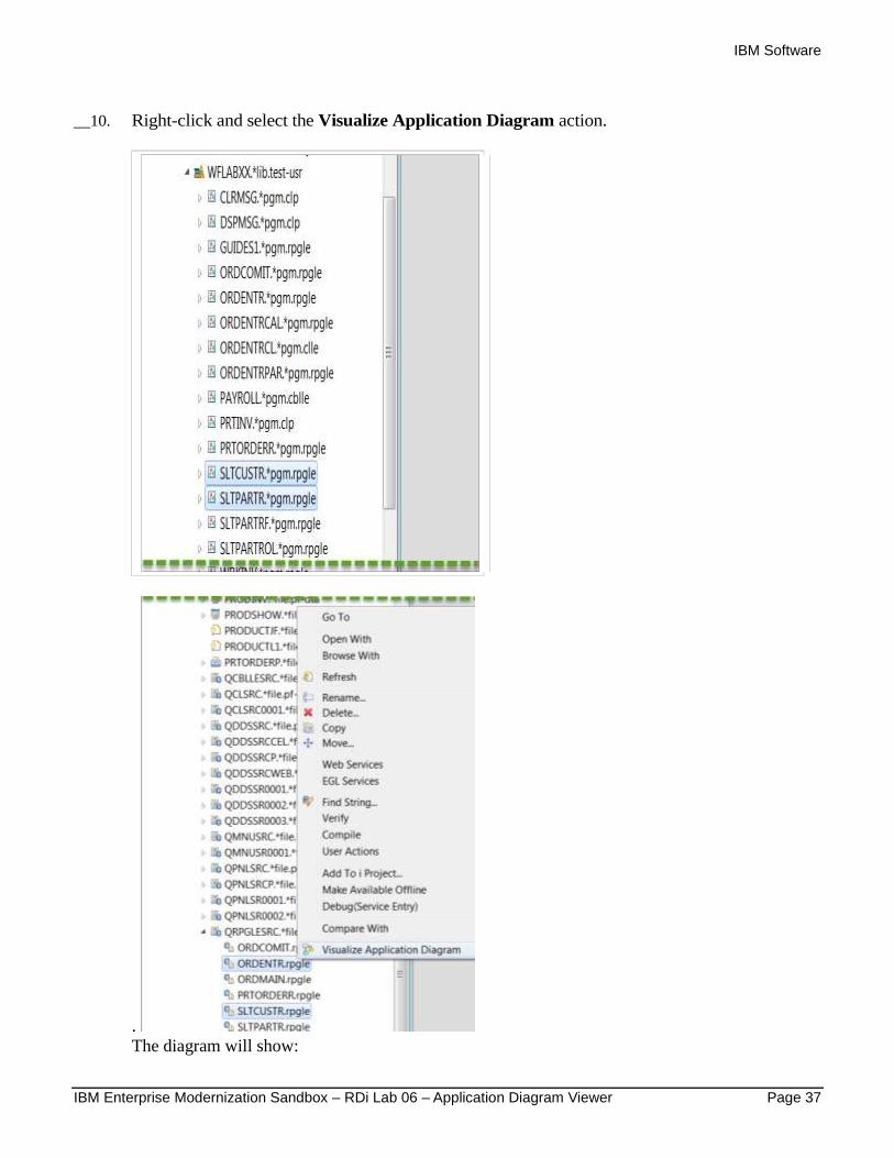
__10. Right-click and select the Visualize Application Diagram action.
.
The diagram will show:

IBM Software
Page 38 IBM Enterprise Modernization Sandbox – RDi Lab 06 – Application Diagram Viewer
The program nodes SLTCUSTR and SLTPARTR now have solid border lines since the
application diagram tool was able to retrieve the detail information from the system. For any
object that is selected at diagram creation the Application Diagram will gather the detailed
information and show the nodes with solid border lines. On the other hand the program object
QSNDDTAQ is still unknown to the diagram and its node is shown with non solid border lines.
The Properties view will show the detail information for a selected object in the diagram, as it
could be gathered at the diagram creation time.
If you only want to show the Source Call diagram:
__11. Right click the Main canvas
__12. Select the Switch view action

IBM Software
IBM Enterprise Modernization Sandbox – RDi Lab 06 – Application Diagram Viewer Page 39
__13. Select the Source Call Diagram action.
Now you will see the Source call diagram only:
You have worked with different diagram views and you have seen the importance of selecting
resources to get access to their property values, for both source members and program
objects.
You also switched views to only select one type of diagram to be shown.

IBM Software
Page 40 IBM Enterprise Modernization Sandbox – RDi Lab 06 – Application Diagram Viewer
6 Changing application diagrams
In addition to making navigation through an application easier, application diagrams can also help you
document applications. To add documentation to a diagram you can annotate it and then save it with the
annotation.
In this module, you will add documentation to the application diagram with notes and text. Then, you
will change text properties to improve readability.
You will now add some information to the SLTPARTR Source call diagram.
6.1 Annotating an application diagram
First, close all editors then create a new application diagram for member SLTPARTR:
__7. Right click one of the tabs in the editor area.
__8. Select the Close all action.
__9. In the RSE view select your RSELABxx (where xx = your team number) then the SLTPARTR
member in source file QWFSRC

IBM Software
IBM Enterprise Modernization Sandbox – RDi Lab 06 – Application Diagram Viewer Page 41
__10. Select the Visualize Application Diagram action.
In the diagram:

IBM Software
Page 42 IBM Enterprise Modernization Sandbox – RDi Lab 06 – Application Diagram Viewer
__11. Right-click the SLTPARTR node and select the Add Note. Action.
This action creates an attached note to the node.
__12. In the text area, enter Main Entry Point
__13. Press Crtl + Enter.
__14. Add some more text.
__15. Click the diagram canvas to finish editing the note.
To work with this note:
__16. Select it and resize it, by moving the cursor over the border until the cursor switches to a double
headed arrow indicates that you can resize it
__17. Select it and move it when you see the cursor switch to four arrows

IBM Software
IBM Enterprise Modernization Sandbox – RDi Lab 06 – Application Diagram Viewer Page 43
__18. Double click it to edit the text.
To add a note to a connection:
__19. Right-click the connection line joining the Process and EndPgm nodes.
__20. Select the Add Note action. This creates an attached note to the connection.
__21. Type Connection Line into the note
__22. Click on the canvas to finish editing the note.
You can attach a note to multiple resources. Attach this note to another connection:
IBM Software
Page 44 IBM Enterprise Modernization Sandbox – RDi Lab 06 – Application Diagram Viewer
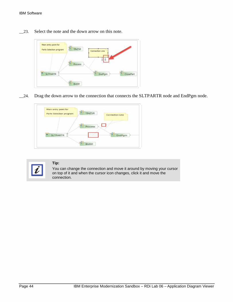
__23. Select the note and the down arrow on this note.
__24. Drag the down arrow to the connection that connects the SLTPARTR node and EndPgm node.
Tip:
You can change the connection and move it around by moving your cursor on top of it and when the cursor icon changes, click it and move the connection.

IBM Software
IBM Enterprise Modernization Sandbox – RDi Lab 06 – Application Diagram Viewer Page 45
6.2 Creating a stand-alone note
Next you will create a stand-alone note (a note that is not attached to any node or connection.)
__1. If the Palette view on the right side of the Main canvas is hidden, click the drop down arrow on
the top right.
__2. In the Palette menu, click Note.
__3. Click the drop down arrow to expand the controls list in the Palette view for the Application
Diagram Tool
__4. Click the Note object to select it
__5. Click anywhere on the diagram’s canvas. to add a note at this position.
__6. Enter some text in the note.
__7. Click on the diagram canvas to finish editing the note.
A stand-alone note is created. A stand-alone note is not connected to any object within the
diagram.

IBM Software
Page 46 IBM Enterprise Modernization Sandbox – RDi Lab 06 – Application Diagram Viewer
6.3 Creating text
Next you will create stand-alone text. Text is a little different from a note, it has a transparent background,
whereas you can set the background color of notes.
__1. In the Palette view, click the drop-down arrow on Notes icon.
__2. Click the Text object to select it
__3. Click anywhere on the diagram’s canvas, and enter some text into the Entry field.
6.4 Changing properties for objects in diagrams
To change the properties for the objects in the diagram:
__1. Right click on the blank canvas, outside of the member rectangle.
__2. Click the Properties action.
The Properties view opens.
IBM Software
IBM Enterprise Modernization Sandbox – RDi Lab 06 – Application Diagram Viewer Page 47
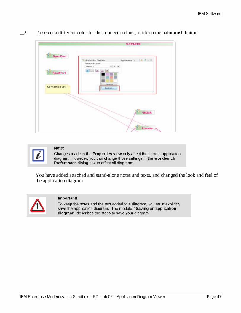
__3. To select a different color for the connection lines, click on the paintbrush button.
Note:
Changes made in the Properties view only affect the current application diagram. However, you can change those settings in the workbench Preferences dialog box to affect all diagrams.
You have added attached and stand-alone notes and texts, and changed the look and feel of
the application diagram.
Important!
To keep the notes and the text added to a diagram, you must explicitly save the application diagram. The module, ″Saving an application diagram″, describes the steps to save your diagram.
IBM Software
Page 48 IBM Enterprise Modernization Sandbox – RDi Lab 06 – Application Diagram Viewer
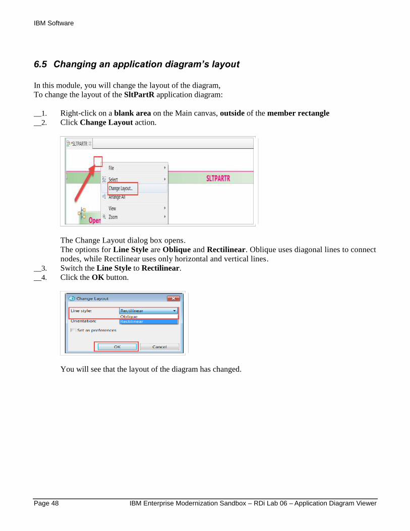
6.5 Changing an application diagram’s layout
In this module, you will change the layout of the diagram,
To change the layout of the SltPartR application diagram:
__1. Right-click on a blank area on the Main canvas, outside of the member rectangle
__2. Click Change Layout action.
The Change Layout dialog box opens.
The options for Line Style are Oblique and Rectilinear. Oblique uses diagonal lines to connect
nodes, while Rectilinear uses only horizontal and vertical lines.
__3. Switch the Line Style to Rectilinear.
__4. Click the OK button.
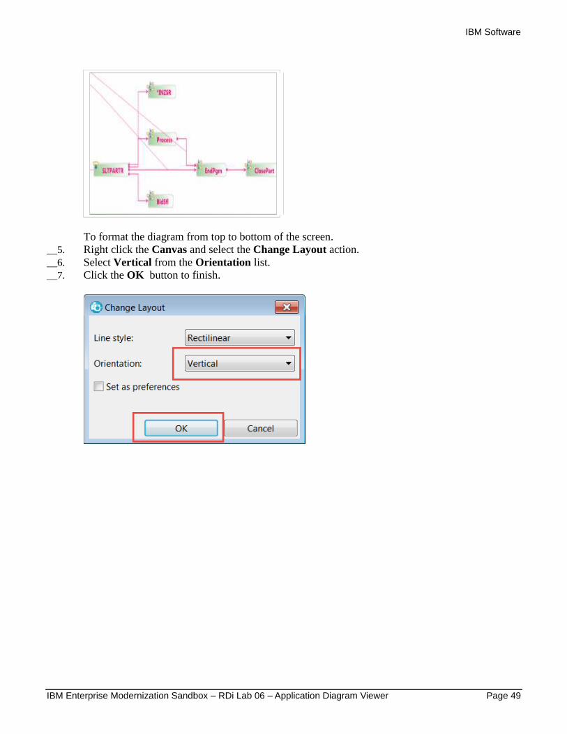
You will see that the layout of the diagram has changed.
IBM Software
IBM Enterprise Modernization Sandbox – RDi Lab 06 – Application Diagram Viewer Page 49
To format the diagram from top to bottom of the screen.
__5. Right click the Canvas and select the Change Layout action.
__6. Select Vertical from the Orientation list.
__7. Click the OK button to finish.
IBM Software
Page 50 IBM Enterprise Modernization Sandbox – RDi Lab 06 – Application Diagram Viewer
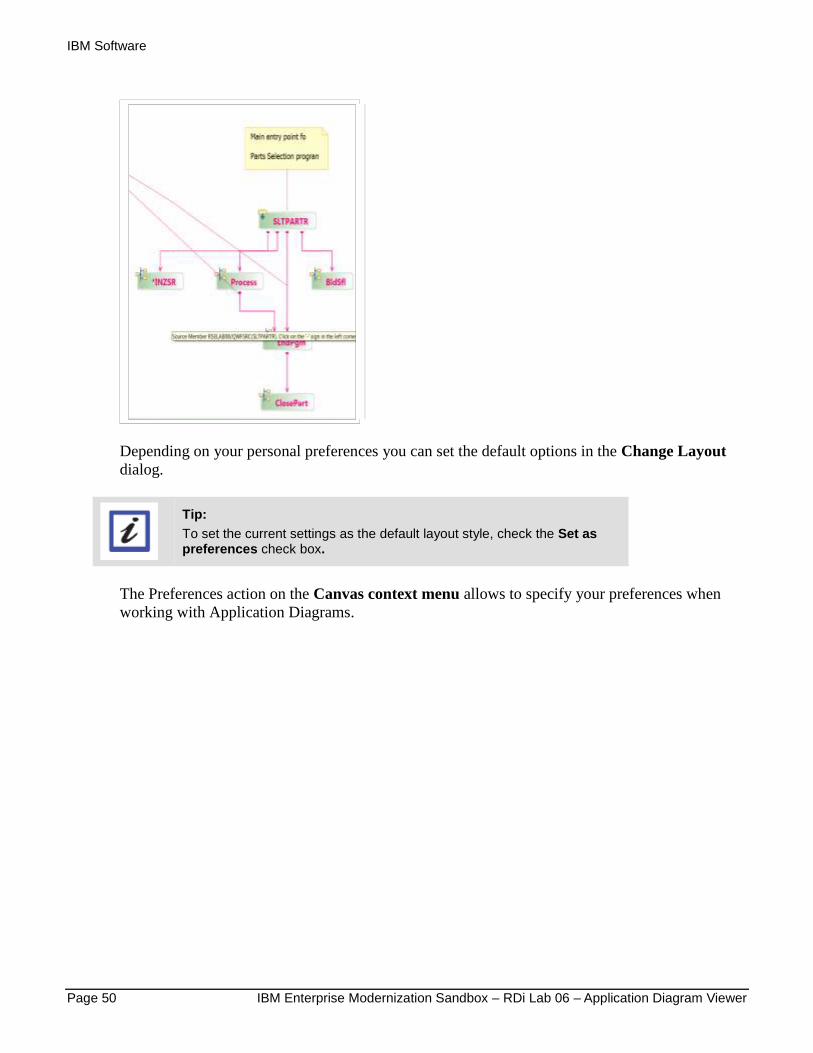
Depending on your personal preferences you can set the default options in the Change Layout
dialog.
Tip:
To set the current settings as the default layout style, check the Set as preferences check box.
The Preferences action on the Canvas context menu allows to specify your preferences when
working with Application Diagrams.

IBM Software
IBM Enterprise Modernization Sandbox – RDi Lab 06 – Application Diagram Viewer Page 51
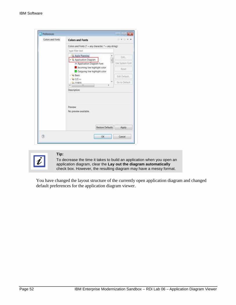
__8. Right-click on a blank area in the canvas and click Preferences > Application Diagram.
Here is the Application Diagram Preference dialog:
Here is the Color and Fonts Preference dialog:
IBM Software
Page 52 IBM Enterprise Modernization Sandbox – RDi Lab 06 – Application Diagram Viewer
Tip:
To decrease the time it takes to build an application when you open an application diagram, clear the Lay out the diagram automatically check box. However, the resulting diagram may have a messy format.
You have changed the layout structure of the currently open application diagram and changed
default preferences for the application diagram viewer.
IBM Software
IBM Enterprise Modernization Sandbox – RDi Lab 06 – Application Diagram Viewer Page 53
7 Storing an application diagram for future use
You can save an application diagram in different formats:
1. As a diagram for further re-use.
2. As a text file, that can be searched or copied.
3. As a image file, to be shared with others or to be embedded in a document.
If you apply any changes to a diagram or a add comments in the diagram you will have to save the
diagram to preserve these changes. When you create a new diagram none of your changes will be
reflected, the diagram is created from scratch.
First you will save the diagram for further reuse.
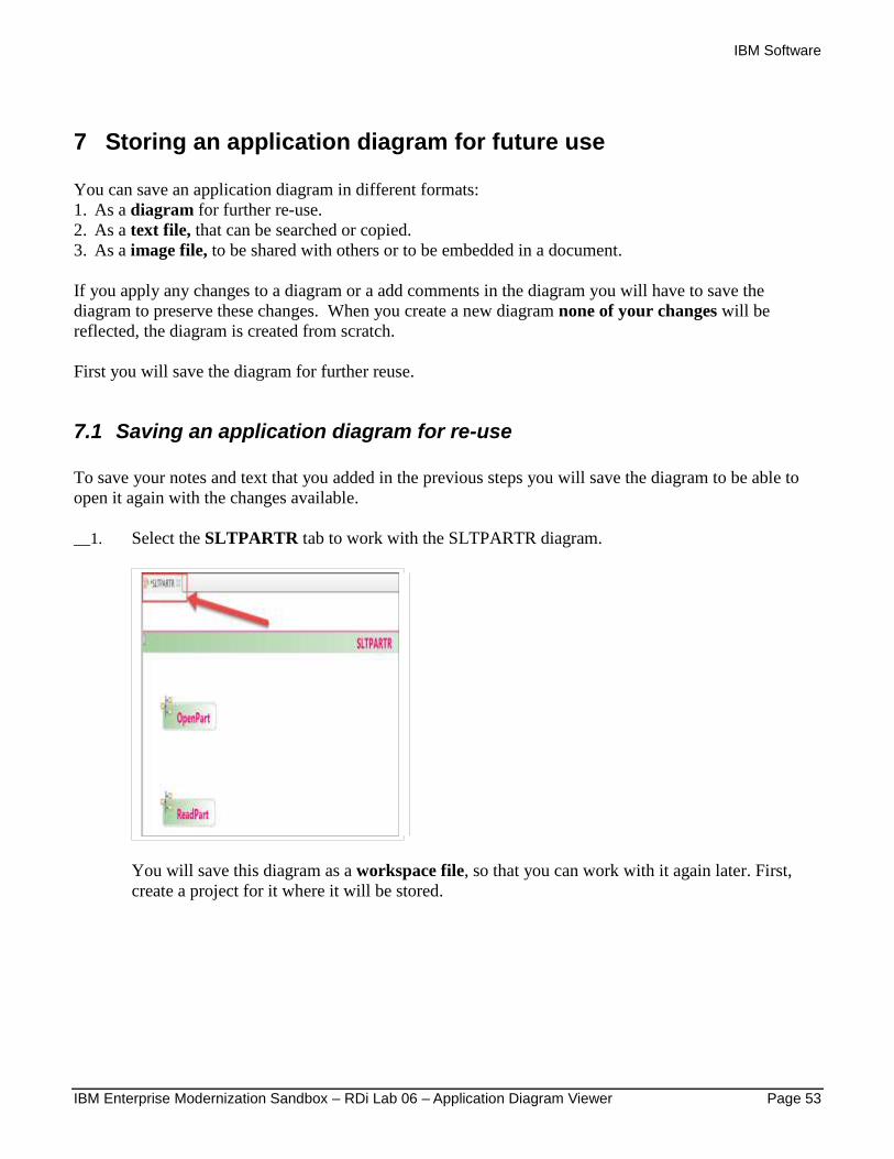
7.1 Saving an application diagram for re-use
To save your notes and text that you added in the previous steps you will save the diagram to be able to
open it again with the changes available.
__1. Select the SLTPARTR tab to work with the SLTPARTR diagram.
You will save this diagram as a workspace file, so that you can work with it again later. First,
create a project for it where it will be stored.
IBM Software
Page 54 IBM Enterprise Modernization Sandbox – RDi Lab 06 – Application Diagram Viewer
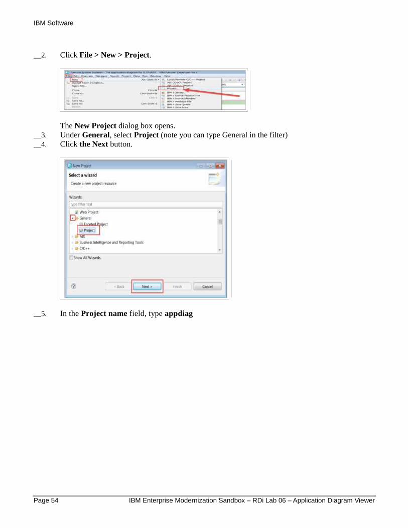
__2. Click File > New > Project.
The New Project dialog box opens.
__3. Under General, select Project (note you can type General in the filter)
__4. Click the Next button.
__5. In the Project name field, type appdiag
IBM Software
IBM Enterprise Modernization Sandbox – RDi Lab 06 – Application Diagram Viewer Page 55
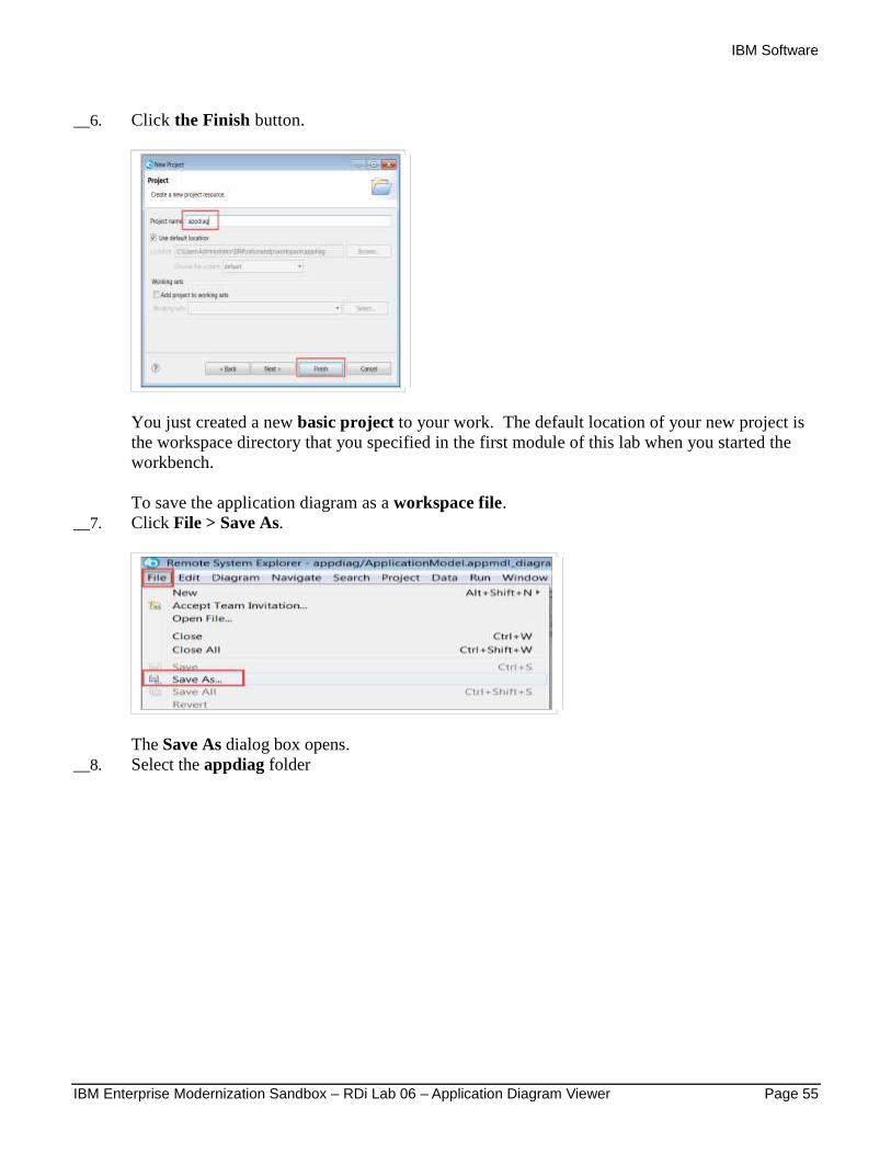
__6. Click the Finish button.
You just created a new basic project to your work. The default location of your new project is
the workspace directory that you specified in the first module of this lab when you started the
workbench.
To save the application diagram as a workspace file.
__7. Click File > Save As.
The Save As dialog box opens.
__8. Select the appdiag folder
IBM Software
Page 56 IBM Enterprise Modernization Sandbox – RDi Lab 06 – Application Diagram Viewer
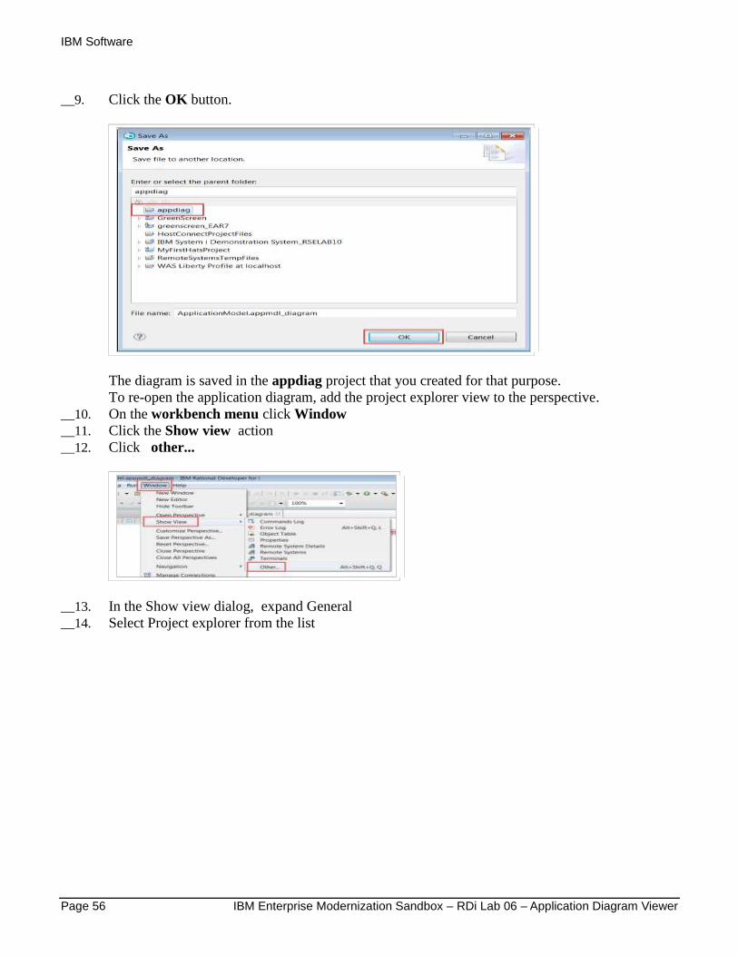
__9. Click the OK button.
The diagram is saved in the appdiag project that you created for that purpose.
To re-open the application diagram, add the project explorer view to the perspective.
__10. On the workbench menu click Window
__11. Click the Show view action
__12. Click other...
__13. In the Show view dialog, expand General
__14. Select Project explorer from the list
IBM Software
IBM Enterprise Modernization Sandbox – RDi Lab 06 – Application Diagram Viewer Page 57
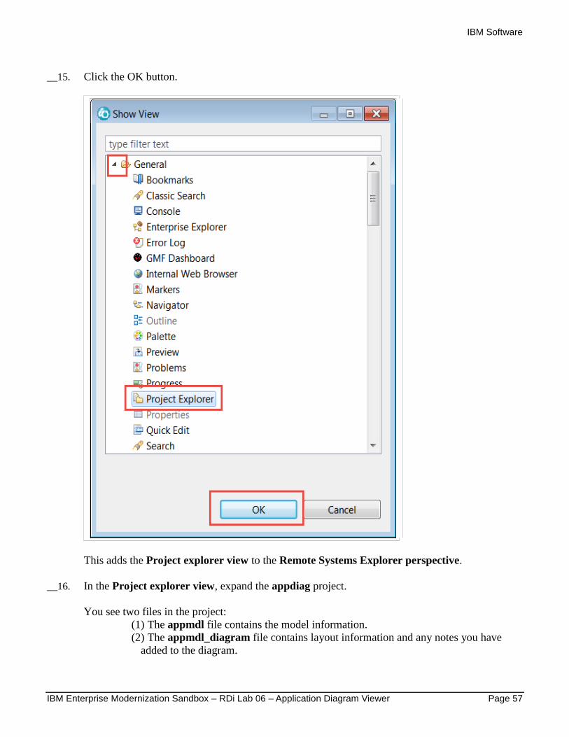
__15. Click the OK button.
This adds the Project explorer view to the Remote Systems Explorer perspective.
__16. In the Project explorer view, expand the appdiag project.
You see two files in the project:
(1) The appmdl file contains the model information.
(2) The appmdl_diagram file contains layout information and any notes you have
added to the diagram.

IBM Software
Page 58 IBM Enterprise Modernization Sandbox – RDi Lab 06 – Application Diagram Viewer
__17. To reopen the diagram, double click on one of the two files.
7.2 Saving a diagram as a text file
Next, you will save the diagram as a text file. Do this when you want a format that you can easily share,
duplicate, and search.
Tip:
Make sure you click out side of the member rectangle on the canvas
__1. Right-click on a blank section of the canvas and click File > Save As Text File.
The Save As Text File dialog box opens.
__2. Enter a Folder and File name (c:\temp and SLTPARTR , check box to Overwrite)
IBM Software
IBM Enterprise Modernization Sandbox – RDi Lab 06 – Application Diagram Viewer Page 59
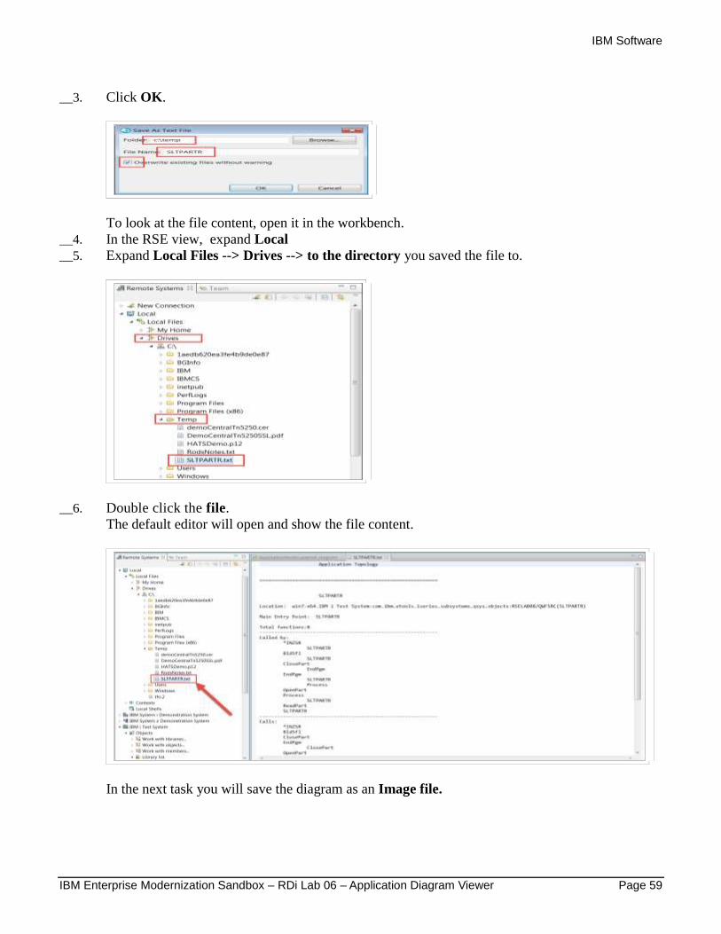
__3. Click OK.
To look at the file content, open it in the workbench.
__4. In the RSE view, expand Local
__5. Expand Local Files --> Drives --> to the directory you saved the file to.
__6. Double click the file.
The default editor will open and show the file content.
In the next task you will save the diagram as an Image file.
IBM Software
Page 60 IBM Enterprise Modernization Sandbox – RDi Lab 06 – Application Diagram Viewer
7.3 Saving a diagram or parts of a diagram as an image file
You might do this to share or embed an entire diagram or a portion of a diagram as a part of a larger
document.
This is very similar to saving a diagram as text file, which you just did in the previous steps. We show
you briefly how to save an entire diagram, and go through the detailed steps of saving portions of a
diagram.
For saving as an image, you can select from multiple file types you want to save to:
1. gif
2. bmp
3. jpeg
4. jpg
5. svg
6. png
7. pdf
In addition you can specify to create HTML to easily show the image in a web browser.
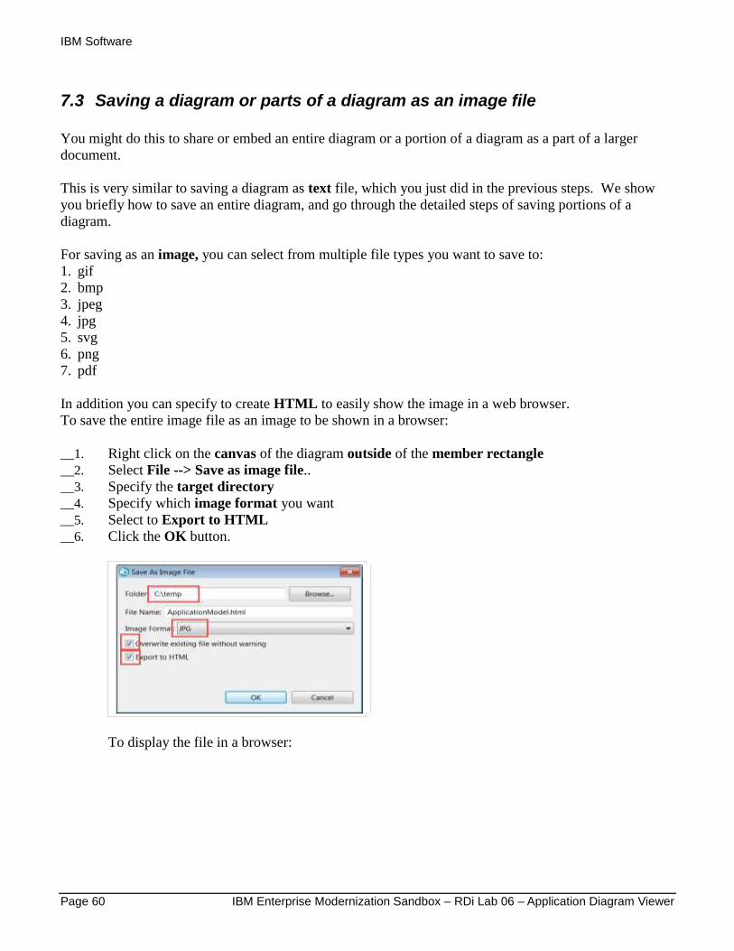
To save the entire image file as an image to be shown in a browser:
__1. Right click on the canvas of the diagram outside of the member rectangle
__2. Select File --> Save as image file..
__3. Specify the target directory
__4. Specify which image format you want
__5. Select to Export to HTML
__6. Click the OK button.
To display the file in a browser:
IBM Software
IBM Enterprise Modernization Sandbox – RDi Lab 06 – Application Diagram Viewer Page 61
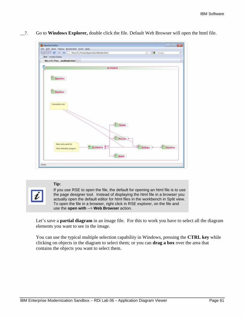
__7. Go to Windows Explorer, double click the file. Default Web Browser will open the html file.
Tip:
If you use RSE to open the file, the default for opening an html file is to use the page designer tool. Instead of displaying the html file in a browser you actually open the default editor for html files in the workbench in Split view. To open the file in a browser, right click in RSE explorer, on the file and use the open with --> Web Browser action.
Let’s save a partial diagram in an image file. For this to work you have to select all the diagram
elements you want to see in the image.
You can use the typical multiple selection capability in Windows, pressing the CTRL key while
clicking on objects in the diagram to select them; or you can drag a box over the area that
contains the objects you want to select them.
IBM Software
Page 62 IBM Enterprise Modernization Sandbox – RDi Lab 06 – Application Diagram Viewer
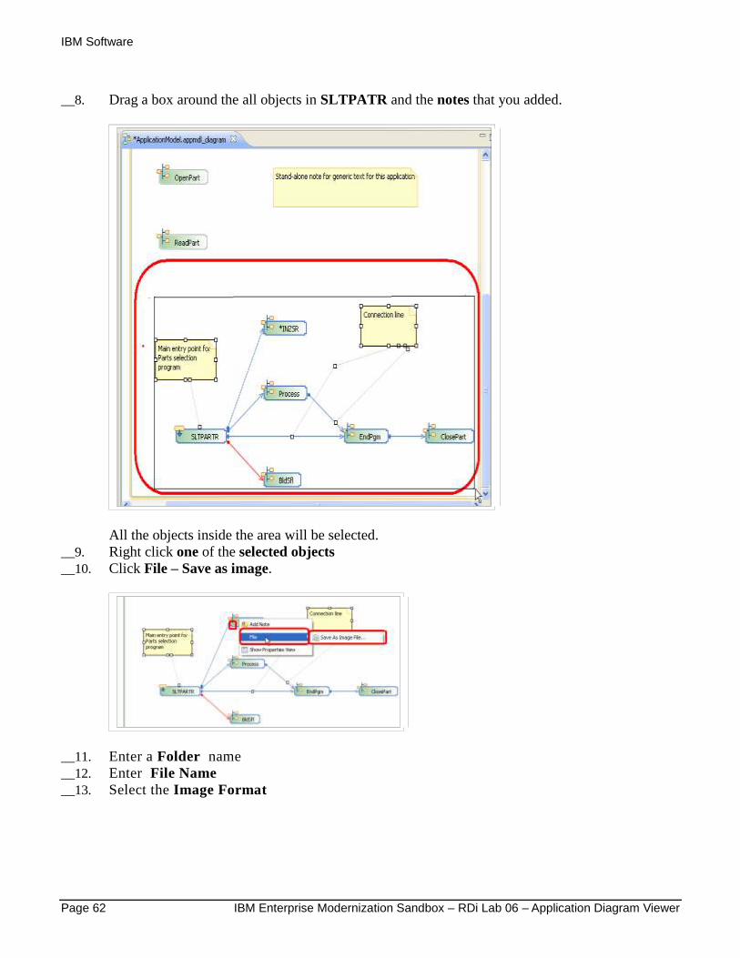
__8. Drag a box around the all objects in SLTPATR and the notes that you added.
All the objects inside the area will be selected.
__9. Right click one of the selected objects
__10. Click File – Save as image.
__11. Enter a Folder name
__12. Enter File Name
__13. Select the Image Format
IBM Software
IBM Enterprise Modernization Sandbox – RDi Lab 06 – Application Diagram Viewer Page 63
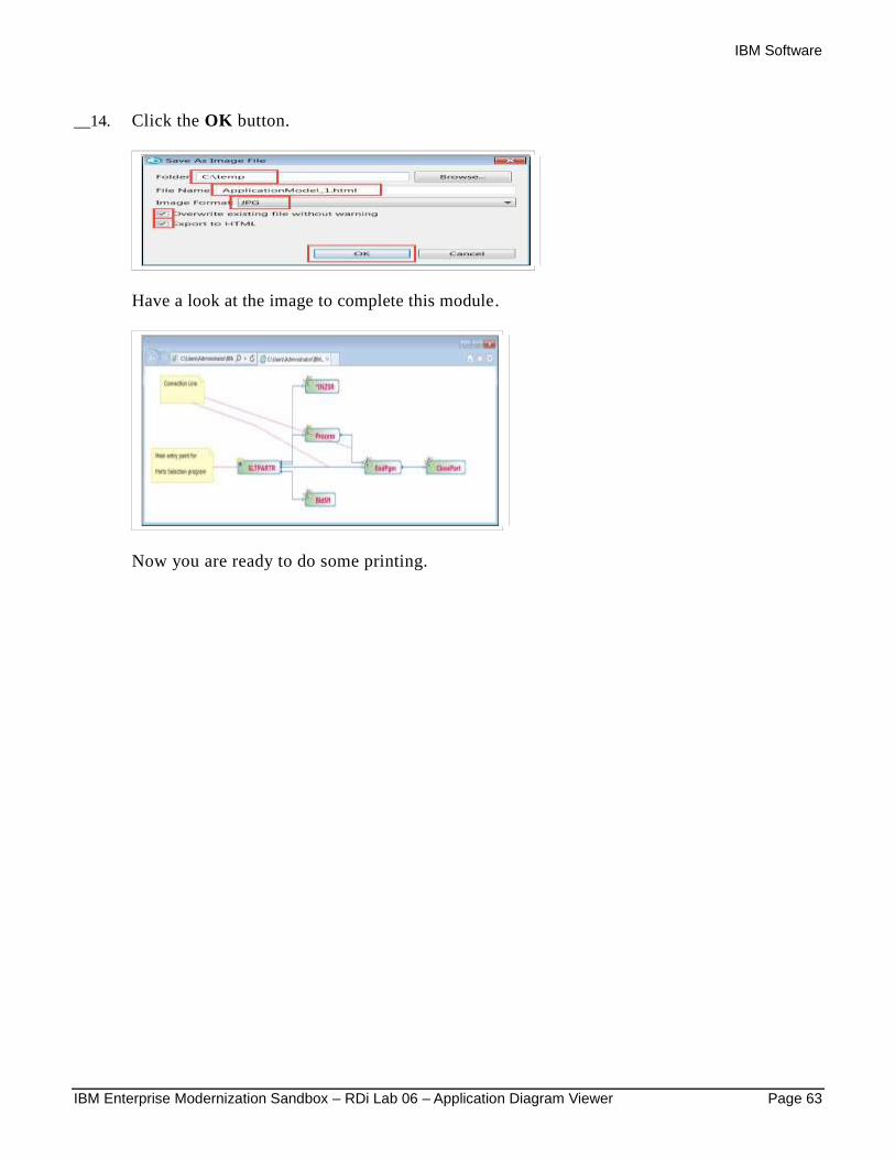
__14. Click the OK button.
Have a look at the image to complete this module.
Now you are ready to do some printing.
IBM Software
Page 64 IBM Enterprise Modernization Sandbox – RDi Lab 06 – Application Diagram Viewer
8 Printing an application diagram
In this module, you will print an application diagram.
Tip:
You will only be able to print a diagram if you have a printer configured and connected to your workstation. If you are using one of the images provided by the developerWorks EM Sandbox portal, this is not the case, so you can skip this module.
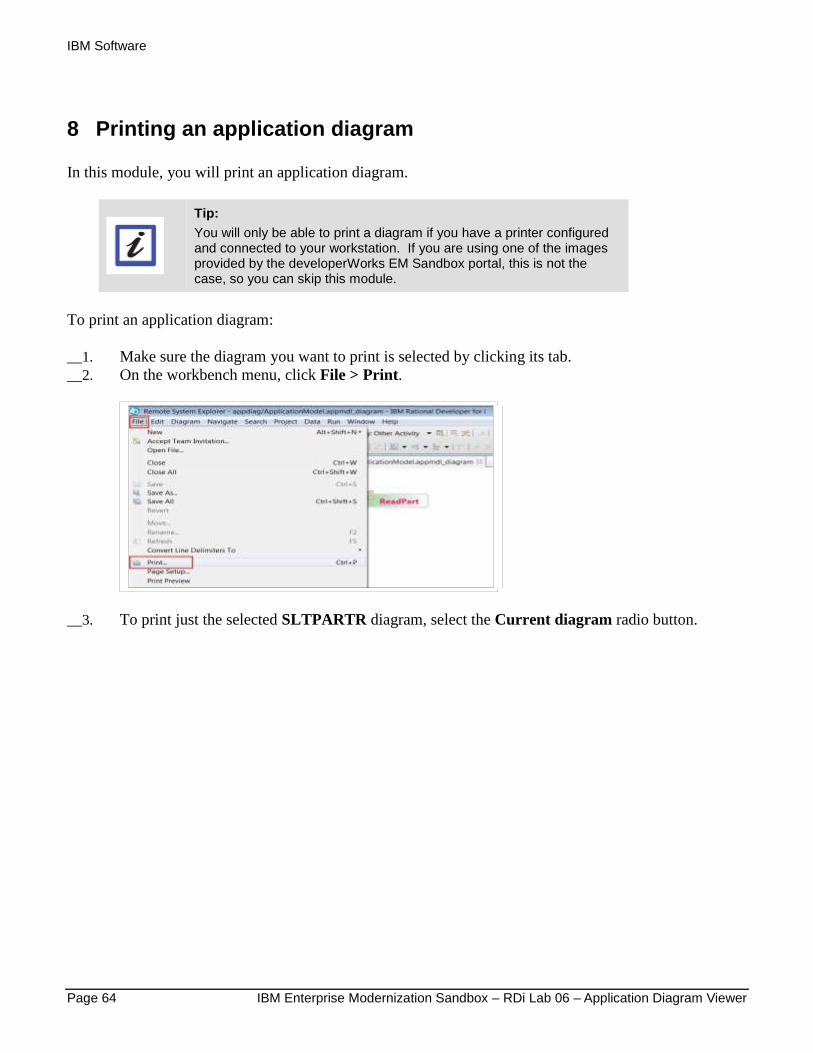
To print an application diagram:
__1. Make sure the diagram you want to print is selected by clicking its tab.
__2. On the workbench menu, click File > Print.
__3. To print just the selected SLTPARTR diagram, select the Current diagram radio button.
IBM Software
IBM Enterprise Modernization Sandbox – RDi Lab 06 – Application Diagram Viewer Page 65
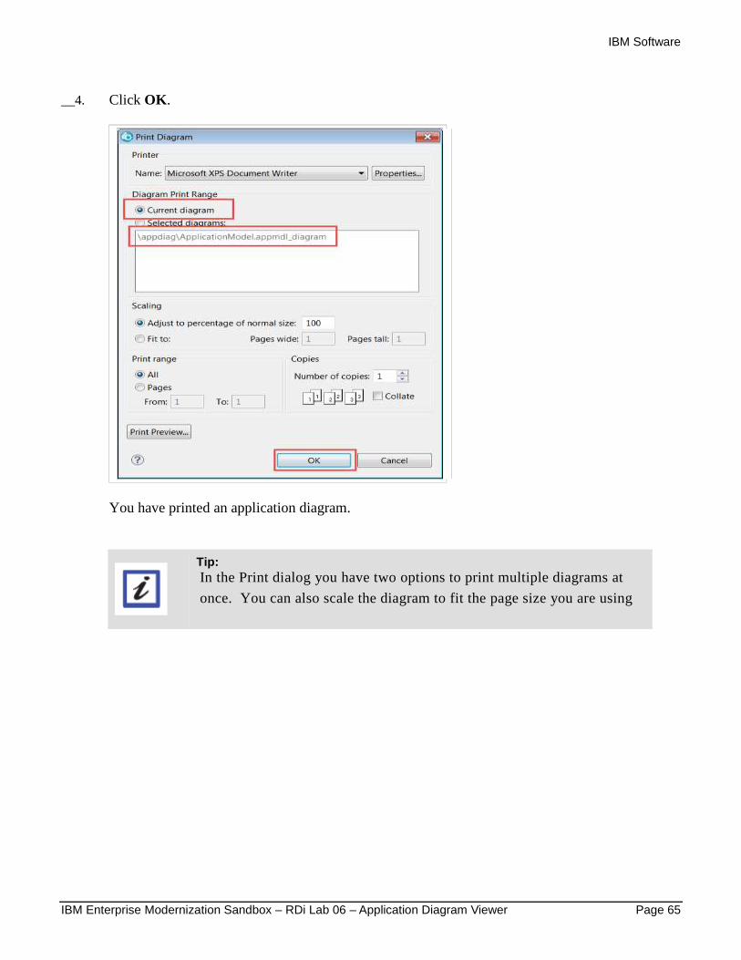
__4. Click OK.
You have printed an application diagram.
Tip: In the Print dialog you have two options to print multiple diagrams at
once. You can also scale the diagram to fit the page size you are using

IBM Software
Page 66 IBM Enterprise Modernization Sandbox – RDi Lab 06 – Application Diagram Viewer
Congratulations!
You have successfully completed the Introduction to Application Diagram Viewer lab exercises.
You have completed working with the Application Diagram Viewer. You learned how to launch an
application diagram, using a Source Call diagram and a Program Structure diagram. You changed
the preferences and layouts of those diagrams.
You also learned how to work in the application diagram’s canvas and its Outline view to easily navigate
to areas of interest and launch the source editor to work with the source members related to the nodes and
connections in the diagram.
Finally, you saved the application diagrams in different formats to re-use the diagrams later or to share
them with other people.
We recommend that you move on to the next lab in the sequence; or browse the list of labs on Rational
Developer for i - Hands-On Labs at http://ibm.biz/rdi_labs to choose a lab of interest.
More information, material and opportunities to discuss the product can be found at our RDi Hub:
http://ibm.biz/rdi_hub
IBM Software
IBM Enterprise Modernization Sandbox – RDi Lab 06 – Application Diagram Viewer Page 67
Appendix A Notices
This information was developed for products and services offered in the U.S.A.
IBM may not offer the products, services, or features discussed in this document in other countries.
Consult your local IBM representative for information on the products and services currently available in
your area. Any reference to an IBM product, program, or service is not intended to state or imply that only
that IBM product, program, or service may be used. Any functionally equivalent product, program, or
service that does not infringe any IBM intellectual property right may be used instead. However, it is the
user's responsibility to evaluate and verify the operation of any non-IBM product, program, or service.
IBM may have patents or pending patent applications covering subject matter described in this document.
The furnishing of this document does not grant you any license to these patents. You can send license
inquiries, in writing, to:
IBM Director of Licensing
IBM Corporation
North Castle Drive
Armonk, NY 10504-1785
U.S.A.
For license inquiries regarding double-byte (DBCS) information, contact the IBM Intellectual Property
Department in your country or send inquiries, in writing, to:
IBM World Trade Asia Corporation
Licensing
2-31 Roppongi 3-chome, Minato-ku
Tokyo 106-0032, Japan
The following paragraph does not apply to the United Kingdom or any other country where such
provisions are inconsistent with local law: INTERNATIONAL BUSINESS MACHINES
CORPORATION PROVIDES THIS PUBLICATION "AS IS" WITHOUT WARRANTY OF ANY
KIND, EITHER EXPRESS OR IMPLIED, INCLUDING, BUT NOT LIMITED TO, THE IMPLIED
WARRANTIES OF NON-INFRINGEMENT, MERCHANTABILITY OR FITNESS FOR A
PARTICULAR PURPOSE. Some states do not allow disclaimer of express or implied warranties in
certain transactions, therefore, this statement may not apply to you.
This information could include technical inaccuracies or typographical errors. Changes are periodically
made to the information herein; these changes will be incorporated in new editions of the publication.
IBM may make improvements and/or changes in the product(s) and/or the program(s) described in this
publication at any time without notice.
Any references in this information to non-IBM Web sites are provided for convenience only and do not in
any manner serve as an endorsement of those Web sites. The materials at those Web sites are not part of
the materials for this IBM product and use of those Web sites is at your own risk.
IBM may use or distribute any of the information you supply in any way it believes appropriate without
incurring any obligation to you.
Any performance data contained herein was determined in a controlled environment. Therefore, the
results obtained in other operating environments may vary significantly. Some measurements may have
IBM Software
Page 68 IBM Enterprise Modernization Sandbox – RDi Lab 06 – Application Diagram Viewer
been made on development-level systems and there is no guarantee that these measurements will be the
same on generally available systems. Furthermore, some measurements may have been estimated through
extrapolation. Actual results may vary. Users of this document should verify the applicable data for their
specific environment.
Information concerning non-IBM products was obtained from the suppliers of those products, their
published announcements or other publicly available sources. IBM has not tested those products and
cannot confirm the accuracy of performance, compatibility or any other claims related to non-IBM
products. Questions on the capabilities of non-IBM products should be addressed to the suppliers of those
products.
All statements regarding IBM's future direction and intent are subject to change or withdrawal without
notice, and represent goals and objectives only.
This information contains examples of data and reports used in daily business operations. To illustrate
them as completely as possible, the examples include the names of individuals, companies, brands, and
products. All of these names are fictitious and any similarity to the names and addresses used by an actual
business enterprise is entirely coincidental. All references to fictitious companies or individuals are used
for illustration purposes only.
COPYRIGHT LICENSE:
This information contains sample application programs in source language, which illustrate programming
techniques on various operating platforms. You may copy, modify, and distribute these sample programs
in any form without payment to IBM, for the purposes of developing, using, marketing or distributing
application programs conforming to the application programming interface for the operating platform for
which the sample programs are written. These examples have not been thoroughly tested under all
conditions. IBM, therefore, cannot guarantee or imply reliability, serviceability, or function of these
programs.
IBM Software
IBM Enterprise Modernization Sandbox – RDi Lab 06 – Application Diagram Viewer Page 69
Appendix B Trademarks and copyrights
The following terms are trademarks of International Business Machines Corporation in the United States,
other countries, or both:
IBM AIX CICS ClearCase ClearQuest Cloudscape
Cube Views DB2 developerWorks DRDA IMS IMS/ESA
Informix Lotus Lotus Workflow MQSeries OmniFind
Rational Redbooks Red Brick RequisitePro System i
System z Tivoli WebSphere Workplace System p
Adobe, Acrobat, Portable Document Format (PDF), and PostScript are either registered trademarks or
trademarks of Adobe Systems Incorporated in the United States, other countries, or both.
Cell Broadband Engine is a trademark of Sony Computer Entertainment, Inc. in the United States, other
countries, or both and is used under license therefrom.
Java and all Java-based trademarks and logos are trademarks of Sun Microsystems, Inc. in the United
States, other countries, or both. See Java Guidelines
Microsoft, Windows, Windows NT, and the Windows logo are trademarks of Microsoft Corporation in
the United States, other countries, or both.
Intel, Intel logo, Intel Inside, Intel Inside logo, Intel Centrino, Intel Centrino logo, Celeron, Intel Xeon,
Intel SpeedStep, Itanium, and Pentium are trademarks or registered trademarks of Intel Corporation or its
subsidiaries in the United States and other countries.
UNIX is a registered trademark of The Open Group in the United States and other countries.
Linux is a registered trademark of Linus Torvalds in the United States, other countries, or both.
ITIL is a registered trademark and a registered community trademark of the Office of Government
Commerce, and is registered in the U.S. Patent and Trademark Office.
IT Infrastructure Library is a registered trademark of the Central Computer and Telecommunications
Agency which is now part of the Office of Government Commerce.
Other company, product and service names may be trademarks or service marks of others.

IBM Software
© Copyright IBM Corporation 2016
The information contained in these materials is provided for
informational purposes only, and is provided AS IS without
warranty of any kind, express or implied. IBM shall not be
responsible for any damages arising out of the use of, or otherwise
related to, these materials. Nothing contained in these materials is
intended to, nor shall have the effect of, creating any warranties or
representations from IBM or its suppliers or licensors, or altering
the terms and conditions of the applicable license agreement
governing the use of IBM software. References in these materials
to IBM products, programs, or services do not imply that they will
be available in all countries in which IBM operates. This
information is based on current IBM product plans and strategy,
which are subject to change by IBM without notice. Product
release dates and/or capabilities referenced in these materials may
change at any time at IBM’s sole discretion based on market
opportunities or other factors, and are not intended to be a
commitment to future product or feature availability in any way.
IBM, the IBM logo and ibm.com are trademarks or registered
trademarks of International Business Machines Corporation in the
United States, other countries, or both. If these and other IBM
trademarked terms are marked on their first occurrence in this
information with a trademark symbol (® or ™), these symbols
indicate U.S. registered or common law trademarks owned by IBM
at the time this information was published. Such trademarks may
also be registered or common law trademarks in other countries. A
current list of IBM trademarks is available on the Web at
“Copyright and trademark information” at
ibm.com/legal/copytrade.shtml
Other company, product and service names may be trademarks or
service marks of others.