ENTERPRISE LEVEL NETWORK DESIGN AND...
67
1 UNIVERSITY OF NAIROBI FACULTY OF ENGINEERING DEPARTMENT OF ELECTRICAL AND INFORMATION ENGINEERING ENTERPRISE LEVEL NETWORK DESIGN AND OPTIMIZATION PROJECT INDEX: PRJ 072 BY MBUTHIA MICHAEL MWANGI F17/1754/2006 SUPERVISOR: DR. C. WEKESA EXAMINER: DR. KAMUCHA PROJECT REPORT SUBMITTED IN PARTIAL FULFILMENT OF THE REQUIREMENT FOR THE AWARD OF THE DEGREE OF BACHELOR OF SCIENCE IN ELECTRICAL AND ELECTRONIC ENGINEERING OF THE UNIVERSITY OF NAIROBI 2011 Submitted on: 18 th May, 2011
Transcript of ENTERPRISE LEVEL NETWORK DESIGN AND...

1
UNIVERSITY OF NAIROBI
FACULTY OF ENGINEERING
DEPARTMENT OF ELECTRICAL AND INFORMATION ENGINEERING
ENTERPRISE LEVEL NETWORK DESIGN AND OPTIMIZATION
PROJECT INDEX: PRJ 072
BY
MBUTHIA MICHAEL MWANGI
F17/1754/2006
SUPERVISOR: DR. C. WEKESA
EXAMINER: DR. KAMUCHA
PROJECT REPORT SUBMITTED IN PARTIAL FULFILMENT OF THE
REQUIREMENT FOR THE AWARD OF THE DEGREE
OF
BACHELOR OF SCIENCE IN ELECTRICAL AND ELECTRONIC
ENGINEERING OF THE UNIVERSITY OF NAIROBI 2011
Submitted on:
18th
May, 2011

i
DECLARATION AND CERTIFICATION
This BSc. work is my original work and has not been presented for a degree award in this or any
other university.
Signed……………………………………….. Date……………………..
MBUTHIA MICHAEL MWANGI
F17/1754/2006
This report has been submitted to the Dept. of Electrical and Information Engineering,
University of Nairobi with my approval as supervisor:
Signed……………………………………….. Date…………………….
DR. CYRUS WEKESA
(Supervisor)

ii
ACKNOWLEDGEMENTS
I thank the Almighty God for giving me the mental and physical strength to undertake this
project.
My gratitude also goes to Dr. Wekesa, my supervisor, who greatly assisted and supported me
throughout the project preparation period. Finally, I thank Mr. Aseda of KENET, proof-reader
Catherine Wanjiru, and my colleagues for their continued support.

iii
TABLE OF CONTENTS
Contents
DECLARATION AND CERTIFICATION i
ACKNOWLEDGEMENTS ii
TABLE OF CONTENTS iii
LIST OF ABBREVIATIONS v
ABSTRACT vii
CHAPTER 1: INTRODUCTION 1
1.1 Background 1
1.2 Problem Definition 1
1.3 Objective 2
CHAPTER 2: NETWORK DESIGN METHOLOGIES 3
2.1 Introduction 3
2.2 Network Design Methodologies 3
2.2.1 Bottom-up Network Design 3
2.2.2 Top-down Network Design 3
2.3 Requirements Analysis 4
CHAPTER 3: LOGICAL NETWORK DESIGN 8
3.1. Network Topology 8
3.2 Designing a Network Addressing and Naming Model 11
3.2.1 Addressing 11
3.2.2 Naming 13
3.3 Selecting and Implementing Switching and Routing Protocols 14
3.3.1 Routing Protocols 14
3.3.2 Protocols and the Hierarchical Design Model 16
3.4 Network Management 16
3.4.1 Network Management Architecture 17
3.4.2 Network Traffic 18
3.4.3 Network Security 18
CHAPTER 4: PHYSICAL NETWORK DESIGN 20
4.1 Introduction 20

iv
4.2 Technologies and Hardware for the LAN 20
4.2.1 Ethernet 20
4.2.2 LAN Cabling 22
4.2.3 Internetworking Devices 23
4.3 Technologies and Hardware for the WAN 24
4.3.1 Remote Access 24
4.3.2 Internetworking Devices 27
CHAPTER 5: TESTING AND OPTIMIZING THE NETWORK DESIGN 28
5.1 Introduction 28
5.2 Testing the Network Design 28
5.2.1 Building and Testing a Prototype 28
5.2.2 Testing Tools 29
5.3 Optimizing the Network Design 30
5.3.1 Performance Mechanisms 30
CHAPTER 6: APPLYING THE METHOLOGY 34
6.1 Background 34
6.2 Business and Technical Goals 34
6.3 Structure 35
6.4 Current Network 36
6.4.1 Traffic flows 37
6.4.2 Inherent Problems of the Current Design: 38
6.5 Proposed Design 38
6.5.1 Connectivity 38
6.5.2 Logical Network Design 39
6.5.3 Physical Network Design 46
6.5.4 Testing and Optimization 50
6.6 Simulation Environment 51
CHAPTER 7: CONCLUSIONS AND RECOMMENDATIONS 54
7.1 Conclusions 54
7.2 Recommendations 54

v
LIST OF ABBREVIATIONS
OSI – Open Systems Interconnect
RMON – Remote Monitoring
RIP – Routing Information Protocol
IGRP – Interior Gateway Routing Protocol
EIGRP – Enhanced Interior Gateway Routing Protocol
OSPF – Open Shortest Path First
BGP – Border Gateway Protocol
ATM – Asynchronous Transfer Mode
PKI – Public Key Infrastructure
LAN – Local Area Network
WAN – Wide Area Network
VLAN – Virtual Local Area Network
IPX – Internetwork Packet Exchange
IP – Internet Protocol
TCP – Transport Control Protocol
DNS – Domain Name Service
DHCP - Dynamic Host Configuration Protocol
NIC - Network Interface Card
MAC - Media Access Control
NAT - Network Address Translation
CPU – Central Processing Unit

vi
DMZ – Demilitarized Zone
RTMP – Routing Table Maintenance Protocol
LSA – Link State Advertisement
WLAN – Wireless Local Area Network
VPN – Virtual Private Network
FDDI – Fiber Distributed Data Interface
RSVP – Resource Reservation Protocol
MCU – Multi-point Control Unit
ISP – Internet Service Provider

vii
ABSTRACT
In the business world, technology plays a major role in shaping the manner in which business is
carried out. Computer networks play an important role in a business environment, since
technological trends have made the computer a vital ingredient in modern business processes.
Internetworks are important to facilitate communication so as to enhance provision of goods
and services. However, these networks ought to be reliable, secure and scalable. This is usually
not the case, as many designers do not make important considerations at the design stage.
This project report tackles enterprise network design using a top-down approach. Firstly,
customer requirements are considered and analyzed, as described in chapter 2. Thereafter, the
logical topology of the network is designed. This is covered in chapter 3 whereby addressing
and naming models are designed and suitable protocols chosen. Other vital areas of concern are
the management and security of the network, which have to be carefully studied and sound
decisions made.
The physical design of the network is discussed in chapter 4. Here, technologies such as
Ethernet are analyzed and networking devices and cabling types examined. The campus area is
considered first, and then the design for the WAN is tackled.
The final stage of this network design approach is the testing of the network and application of
optimization techniques. This is an important stage as it demonstrates the ability of the
designed network to achieve the intended goals. This forms chapter 5 of this report.
A case scenario was then considered. Requirements for the network design process were
analyzed and the design was carried out in a systematic manner in accordance to the top-down
methodology.
It was noted that a structured and systematic network design approach yielded a functional
network that conforms to modern business practices.
1
CHAPTER 1: INTRODUCTION
1.1 Background
Internetworks are an important requirement in facilitating communication and transactions
within an enterprise and between the enterprise and external parties such as customers and
partners. Large internetworks consist of the following three distinct components:
• Campus networks consisting of locally connected users in a building or group of
buildings
• Wide-area networks (WANs) which connect campus networks together
• Remote connections which link remote offices or single users to the main campus
network or to the Internet.
With the ever-changing characteristics of business, it is crucial to develop a network that can
keep pace with the accelerating changes created by business requirements.
1.2 Problem Definition
Most networks created often do not accommodate changes in the business environment. These
changes could be an increase in the number of users on the network, incorporation of video and
voice data, wireless capabilities or e-commerce services. This problem is usually as a result of
poor network design.
Proper internetwork design is employed to come up with a functional network that addresses the
following goals:
• Functionality – the availability, usability and performance of the network.
• Scalability – the ability to support growth in the network.
• Manageability – the ease of management of the network and network resources.
• Adaptability – the ability to implement changes in areas such as technologies, legislation,
and business practices.
2
• Affordability – the cost-effectiveness of the network.
• Security – measures to ensure security problems do not interfere with the company's
ability to conduct business efficiently.
Therefore, designing a suitable internetwork that achieves the above goals is a challenge which
should be carefully and systematically tackled.
1.3 Objective
This project aims at applying structured network design techniques to design and optimize a
modern-day enterprise network which meets business requirements. The top-down network
design methodology is applied.

3
CHAPTER 2: NETWORK DESIGN METHOLOGIES
2.1 Introduction
This chapter introduces network design methodologies and also discusses requirements analysis.
2.2 Network Design Methodologies
There are two main approaches to network design. This classification is roughly based on how
the seven-layer OSI model is traversed. The two methodologies are:
Bottom-up network design methodology
Top-down network design methodology
2.2.1 Bottom-up Network Design
This approach is based on past projects and implementation that worked on the current network
layout. This makes this methodology generally faster. Bottom-up design is cell-based as it
employs a cell-oriented architecture.
Under this methodology, the physical network is considered first. This is because the physical
network layout has to support the applications, and generally, the customer always has a fixed
estimate of the equipment to deploy.
The disadvantage of this approach is that it may not take all necessary applications and services
into consideration, leading to a design that may not meet all the needs of the organization.
2.2.2 Top-down Network Design
Under this methodology, network design is tackled by considering the upper layers of the OSI
reference model moving downwards to the lower layers. The applications and sessions are
considered before selecting the protocols and devices such as routers and switches.
A logical model of the network is developed before the physical model. The logical model is a
representation of the basic building blocks and structure of the system. On the other hand, the
physical model represents networking devices and technologies and their implementation within
the internetwork.

4
The top-down approach is a systematic design methodology that helps meet an organization's
requirements, regardless of the newness or complexity of applications and technologies. This
makes this approach more preferred as compared to the bottom-up network design.
This approach can be broken down to:
1. Analyzing customer's needs and goals.
2. Logical network design.
3. Physical network design
4. Testing and optimizing the network design.
2.3 Requirements Analysis
This is the first stage of top-down network design whereby the customer’s technical goals and
business goals are identified and analyzed. The process of requirements analysis provides a
means for analyzing the network and the environment in which it is contained.
It is essential to understand the company business model, business drivers and projected growth
from a business perspective. This builds the foundation for a network design that serves the
business, technical and operational requirements of the company.
Analyzing the Existing Network
The first step under requirements analysis is to analyze the existing network, if any. This
includes analyzing network health, business constraints and problems that could arise due to
anticipated growth. Data collected under this section is broadly classified as administrative and
technical.
Administrative issues include business goals and policies, corporate structure of the business,
staff matters and politics. It is important to know who in the company supports the change in
network design and who doesn’t. Furthermore, the technical capabilities of the current
employees also come into play as skilled persons will be required to maintain the network. This
may create or eliminate jobs.

5
It is important to document these issues that come into play before embarking on the design
work. Information about the requirements of the network design can be gathered from managers
and users.
When analyzing customer requirements, the following major aspects are considered:
a) Business constraints- resource allocation, time schedule, staff issues.
b) Security requirements- security risks and their mitigation.
c) Management requirements- account management, fault management.
d) Applications requirements- new applications, peak hours.
e) Network traffic- users effect on traffic load.
f) Performance requirements- availability, scalability, manageability, usability, adaptability,
efficiency, utilization.
The following steps provide a guideline to follow when characterizing the current network:
1. Characterize the applications and protocols in use.
2. Analyze the current topology.
3. Characterize the network performance.
4. Analyze network ‘health’ (reliability, availability and utilization).
5. Analyze the status of network devices, for instance, router configurations.
Network Traffic
It is crucial to analyze network traffic patterns so as to guide in selecting appropriate logical and
physical network design solutions to meet the enterprise’s goals. This involves characterizing
traffic flow, traffic volume, and protocol behavior.
Traffic flows are analyzed and bandwidth utilization by protocol measured. This is achieved by
placing a protocol analyzer or RMON probe on every major network segment. The response time
for network-service protocols is tested.
6
User applications are considered and it is determined if they are mission-critical, real-time, or
interactive. Considering the protocols and number of users, the approximate bandwidth used by
the applications is computed.
It is important to characterize traffic load with traffic flow. Traffic load is the total data that
network nodes are ready to send at a given time.
This analysis can be carried out by first approximating the size of objects transferred across
networks by applications. This will entail e-mail messages, general web browsing, and other
applications which transfer data to the Internet.
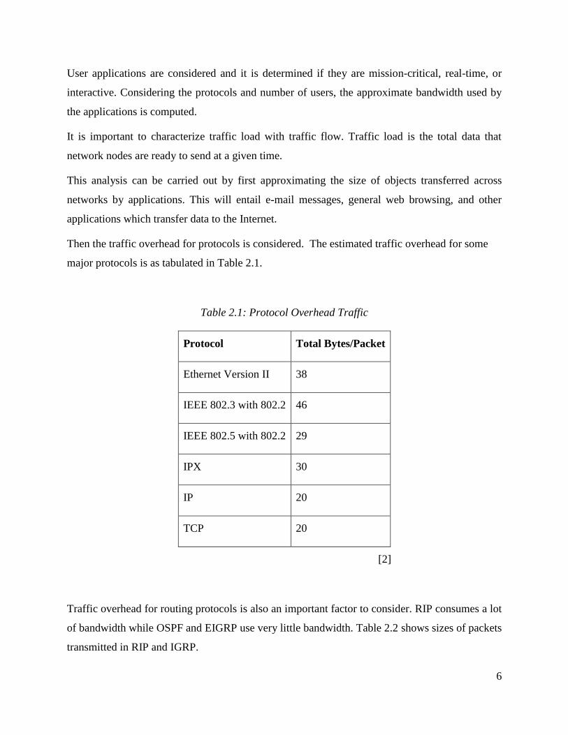
Then the traffic overhead for protocols is considered. The estimated traffic overhead for some
major protocols is as tabulated in Table 2.1.
Table 2.1: Protocol Overhead Traffic
Protocol Total Bytes/Packet
Ethernet Version II 38
IEEE 802.3 with 802.2 46
IEEE 802.5 with 802.2 29
IPX 30
IP 20
TCP 20
[2]
Traffic overhead for routing protocols is also an important factor to consider. RIP consumes a lot
of bandwidth while OSPF and EIGRP use very little bandwidth. Table 2.2 shows sizes of packets
transmitted in RIP and IGRP.

7
Table 2.2: Packet Transmission in Routing Protocols
Routing
Protocol
Default Update
Timer (Seconds)
Route Entry
Size (Bytes)
Routes
Per
Packet
Network and
Update Overhead
(Bytes)
Size of
Full
Packet
IP RIP 30 20 25 32 532
IP IGRP 90 14 104 32 1488
[2]
An important checklist to consider is:
Ethernet segments should not exceed 40% utilization.
WAN segments should not be saturated (links should below 70% utilization).
Broadcast traffic should be less than 20% of all traffic on any network segment.
Collisions on Ethernet segments should not exceed 0.1% of total packets.
Network response time should be less that 100ms.
Routers should not be over-utilized (75% utilization).
Routers should not drop more than 1% of packets.

8
CHAPTER 3: LOGICAL NETWORK DESIGN
This is the stage of top-down network design that immediately supersedes requirements analysis.
After the goals and constraints of the enterprise have been analyzed, the logical network
architecture is then designed.
Logical network design involves:
1. Designing the network topology.
2. Designing an addressing and naming model.
3. Selecting and implementing network protocols.
4. Selecting network management options.
3.1. Network Topology
A map is drawn to describe the geometry of the internetwork. This map is known as the network
topology. It shows network segments and interconnection points.
A hierarchical network design model is used. This is a layered model to tackle network design. It
consists of three major layers (refer to figure 2.1):
Core layer – consists of high end routers. This is the high-speed backbone of the
internetwork. Redundancy is of paramount importance.
Distribution layer – consists of switches and routers. This layer controls network traffic
and does address translation.
Access layer – Includes lower-end switches, hubs and wireless access points to provide
users access to the network.

9
Figure 3.1: Hierarchical topology
Advantages of hierarchical model
1. Cost saving. Only appropriate devices for a particular layer are bought.
Furthermore, management costs are reduced as network management systems can
be distributed to the appropriate layers.
2. Simplicity. The network is fairly easy to understand, no intensive staff training is
required. Testing and fault isolation are consequently straight-forward.
3. Facilitation of change. When change is required, such as adding a device, this is
done on a particular segment without altering the entire network.
4. Saves on CPU load and bandwidth consumption.

10
Flat Topology
A small company may use a flat topology for its relatively small network. Using a mesh
topology ensures redundancy thus guaranteeing network availability.
A full mesh topology provides complete redundancy. Furthermore, there is just a single-link
delay between any two sites; hence the network has good performance.
Figure 3.2: Full mesh network
Full mesh networks are expensive, difficult to troubleshoot, upgrade and optimize. Thus, it is not
advisable to implement this topology, unless it is incorporated into a partial-mesh hierarchical
design.
Generally, when designing a network using the hierarchical model, the access layer is designed
first, then the distribution layer, and finally the core layer. This ensures proper capacity planning
for the distribution and core layers.
Virtual LANs (VLANs)
A VLAN is a logical local area network (LAN) that extends over a group of LAN segments. It is
an emulation of a standard LAN that allows data to flow between devices that are not on the
same physical LAN.

11
VLANs allow for seamless accessibility even when there is physical relocation. This also ensures
that important resources such as databases for a particular department are accessible only to the
concerned persons (users within that VLAN).
Wireless LANs (WLANs)
Wireless local area networks are important to ensure access to the network by roaming users.
Wireless access points use radio frequency (RF) to communicate with wireless clients. A
wireless cell is the area that is covered by a wireless access point. The extent of a wireless cell
should be carefully selected so as to balance the bandwidth and the number of users sharing it.
It is important to place the WLAN on a separate subnet to ease addressing, network management
and security since most of the users are roaming.
3.2 Designing a Network Addressing and Naming Model
3.2.1 Addressing
To meet a customer's goals for scalability, manageability and performance, it is important to
develop a systematic model to allocate and aggregate address space. This eliminates the problem
of running out of addresses or duplication of addresses and simplifies integration of new devices.
The following steps act as a guideline for developing a proper network-layer addressing and
naming model:
1. Design a structured, hierarchical method for addressing the autonomous
systems, subnets and end stations.
2. Come up with a plan for route summarization/aggregation.
3. Plan how the administrative authority of assigning addresses will be
delegated.
4. Develop a model whereby addresses reflect geographical location of the
network segments.
5. Plan to identify special stations such as servers with specific node IDs.
6. Use dynamic addressing for end stations to maximize flexibility.
12
7. For Internet access, use gateways to map private addresses to external
addresses.
Data link layer addresses are known as Media Access Control (MAC) addresses or physical
addresses. These are six-octet numbers that uniquely identify a host, as they are ‘hardcoded’ into
the Network Interface Card (NIC) by the manufacturer.
Network-layer addresses are IP or IPX addresses assigned to a terminal. These can be manually
assigned by typing in the address or automatically assigned using a protocol such as DHCP.
Dynamic Host Configuration Protocol (DHCP)
DHCP does IP address allocation using a client/server model whereby servers allocate network
layer addresses and save data about which addresses have been allocated, while clients
dynamically request address configuration from the servers.
DHCP supports three modes for IP address allocation:
1. Automatic – the DHCP server assigns a permanent IP address to a client.
2. Dynamic – the DHCP server assigns an IP address to a client for a limited time period.
Once the time is up, the address is renewed or released for use by other nodes. This is
referred to as leasing.
3. Manual - the DHCP informs the client of the permanent IP address assigned by the
network administrator.
Dynamic allocation is most commonly used because of its manageability and scalability.
Route Summarization/Aggregation (Supernetting)
This is the process of condensing routing information. This helps reduce the load on the router
and entire network.
For instance:
172.20.130.0
172.20.135.0
172.20.150.0

13
172.20.155.0
The above addresses can be summarized as 172.20.130.0/20. The 20 bits are: 8 bits in the first
octet, 8 bits in the second and 4 bits in the third. This implies that all packets with the first 20 bits
set to 172.20.130.0 should be forwarded to this router.
Public Addresses and Private Addresses
IP addresses are either public or private. Public addresses are registered with a numbering
authority and are globally unique. Private addresses are never routed on the global Internet.
Specific ranges of addresses are reserved for private use:
10.0.0.0 to 10.255.255.255
172.16.0.0 to 172.31.255.255
192.168.0.0 to 192.168.255.255
Network Address Translation (NAT)
This is a mechanism for translating private addresses to public addresses, and vice versa. NAT
has a provision for static addresses for servers (such as web and e-mail servers) that need a fixed
address.
NAT can also offer port translation (overloading addresses) for mapping several addresses to the
same address. This ensures that all traffic from an enterprise has the same address. Port numbers
are used to distinguish separate conversations. This feature reduces the number of required
public addresses.
3.2.2 Naming
It is important that proper naming of network resources (hosts, routers, servers and printers) be
implemented as a good naming model strengthens the performance and availability of a network.
A user should transparently access a service by name rather than address. To map names to
addresses, a suitable naming protocol should be deployed. DNS (Domain Name Service) is a
suitable service to carry out these tasks.
To offer efficient manageability, the naming and addressing of a network should be centrally
managed, though authority can be subordinated.

14
3.3 Selecting and Implementing Switching and Routing Protocols
This is a very important stage in the network design process as the appropriate protocols need to
be selected so as to comply with the technical and business requirements. An understanding of
the switching and routing protocols that a switch or router supports helps the designer select the
best protocol.
3.3.1 Routing Protocols
Routing protocols provide the means for routers to share information so as to make a functional
internetwork. They provide routers with information on the nature of segments they support and
the most efficient paths to reach the destination locations.
There are to broad categories of routing protocols:
1. Distance-vector protocols.
2. Link-state protocols.
3.3.1.1 Distance-Vector Routing Protocols
These protocols communicate information about all known links to peer routers. A distance-
vector routing protocol sends its entire routing table to all neighbours. This consumes a lot of
bandwidth in large internetworks; hence these protocols are mainly associated with medium-
sized or small networks.
These protocols specify the length of the distance vector (course) with a hop count. A hop count
specifies the number of routers or links that must be traversed to reach a destination network.
Examples are:
Routing Information Protocol, RIP (both version 1 and 2)
AppleTalk Routing Table Maintenance Protocol (RTMP)
Novell NetWare Internetwork Packet Exchange Routing Information Protocol (IPX RIP)
The following are derivatives of distance-vector routing protocols:
Border Gateway Protocol (BGP)
Interior Gateway Routing Protocol (IGRP)

15
Enhanced IGRP (EIGRP)
3.3.1.2 Link-State Routing Protocols
These protocols only convey information about directly connected routers. They do not exchange
routing tables and each router learns enough information about links in the internetwork from
peer routers to build its own routing table.
Routers use a hello protocol to establish a relationship (adjacency) with neighbour routers. Each
router sends link-state advertisements (LSAs) to each adjacent router. The LSAs identify links
and metrics. These advertisements are propagated throughout the routers in the network.
Eventually each router has a link-state database that describes the nodes and links in the
internetwork.
Link-state routing uses more CPU and memory resources, but uses less bandwidth than distance-
vector routing, hence is preferred.
Examples:
Open Shortest Path First (OSPF)
IP Intermediate System-to-Intermediate System (IS-IS)
NetWare Link Services Protocol (NLSP).
Link-state routing is recommended when a hierarchical network design is implemented and there
are knowledgeable personnel.
Distance-vector routing is preferred for a flat-topology network where network administrators do
not have enough knowledge to operate link-state protocols.
Open Shortest Path First (OSPF)
This is a link-state hierarchical interior gateway protocol. It features least-cost routing, multi-
path routing and load balancing. It minimizes CPU usage and bandwidth utilization. This is
because an OSPF router propagates only route changes. This is achieved by multicasting link-
state advertisements (LSAs) to all other routers within the same hierarchical area.
OSPF networks are grouped into areas connected to the main backbone. The topology of an area
is hidden from the rest of the autonomous system thus reducing routing traffic. An autonomous
16
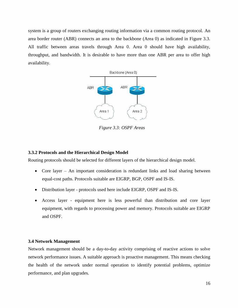
system is a group of routers exchanging routing information via a common routing protocol. An
area border router (ABR) connects an area to the backbone (Area 0) as indicated in Figure 3.3.
All traffic between areas travels through Area 0. Area 0 should have high availability,
throughput, and bandwidth. It is desirable to have more than one ABR per area to offer high
availability.
Figure 3.3: OSPF Areas
3.3.2 Protocols and the Hierarchical Design Model
Routing protocols should be selected for different layers of the hierarchical design model.
Core layer – An important consideration is redundant links and load sharing between
equal-cost paths. Protocols suitable are EIGRP, BGP, OSPF and IS-IS.
Distribution layer - protocols used here include EIGRP, OSPF and IS-IS.
Access layer - equipment here is less powerful than distribution and core layer
equipment, with regards to processing power and memory. Protocols suitable are EIGRP
and OSPF.
3.4 Network Management
Network management should be a day-to-day activity comprising of reactive actions to solve
network performance issues. A suitable approach is proactive management. This means checking
the health of the network under normal operation to identify potential problems, optimize
performance, and plan upgrades.

17
This requires that the network administrator be aware of problems before they negatively affect
network performance. Effective network management helps an organization measure how well
design goals are being met and adjust network parameters if these are not being met.
Main areas of network management are:
1. Implementation and change – installation, configuration, user management and billing.
2. Monitoring and diagnosis – problem isolation and resolution.
3. Design and optimization – base lining, trend analysis, topology design and
procurement.
The International Organization for Standardization (ISO) defines five types of network
management processes:
• Performance management - measurement of network behavior and effectiveness.
• Fault management - detecting, isolating, diagnosing, and correcting problems and
informing end users and managers of these problems.
• Configuration management – keeping track of network devices and information on how
devices are configured.
• Security management - includes processes for generating, distributing, and storing
encryption keys and other authentication and authorization information. Security and
audit logs are maintained.
• Accounting management - facilitates usage-based billing, whereby individual
departments are charged for network services. It shows which terminal or network
segment is responsible for whatever amount of traffic.
3.4.1 Network Management Architecture
A network management architecture consists of managed devices, agents, and NMSs arranged in
a topology that fits into the internetwork topology. A Network Management System (NMS) is a
software platform that runs on a workstation. It runs applications to: display management data,
monitor and control managed devices, and communicate with agents.

18
In the case of in-band monitoring, network management data flows with user traffic. This makes
the network management architecture easy to develop, but susceptible to problems on the
internetwork.
In out-of-band monitoring, network management data travels on paths different from those used
by user data. This offers availability, but calls for extra management as separate links are used.
A centralized monitoring architecture is preferred, whereby network management is
administered from a central location.
3.4.2 Network Traffic
After you determine the management protocols to be used, estimate the amount of traffic caused
by network management. A protocol analyzer would be helpful in getting such statistics.
Management traffic should use less than 5 percent of a network's capacity.
3.4.3 Network Security
Security is a very critical aspect of a network. Network resources such as servers and databases
should be protected from unauthorized access. The logical topology of the network should
incorporate security measures such as firewalls.
A suitable approach to network security would be to create a demilitarized zone (DMZ). A DMZ
is an area between a company's private network and the outside public network. A dedicated
firewall is placed between the Internet and the enterprise network. A public LAN that hosts the
public servers including web, mail, and primary DNS servers is placed behind the firewall but
not within the enterprise private network (Refer to Figure 3.4). This topology enables outsiders
to access only data that they require, such as web pages, and not private company data.
The DMZ hosts intercept traffic and broker requests for the enterprise network. A DMZ host
receives requests from users within the private network for web access. The DMZ host then
initiates sessions for these requests on the public network, but the DMZ host cannot initiate a
session back into the private network.

19
Figure 3.4: Simple DMZ Topology
A network design should ensure that user services are secured. Remote access and wireless
access pose security challenges; therefore, measures must be taken to ensure security prevails on
the network. This is made possible by making use of features such as user authentication and
authorization, data encryption and implementing packet filters and firewalls. For instance, the
RADIUS (Remote Authentication Dial-In User Service) server provides a platform and database
for authenticating users and authorizing services permitted to users.

20
CHAPTER 4: PHYSICAL NETWORK DESIGN
4.1 Introduction
Physical network design involves the selection of LAN and WAN technologies for the
internetwork comprising of campus and enterprise network designs. During this stage of the
network design process, issues considered are cabling, physical and data link layer protocols, and
internetworking devices (switches, routers, and wireless access points).
A suitable approach to physical network design is to consider campus network solutions (LAN)
first, then enterprise network (remote access and WAN) solutions.
4.2 Technologies and Hardware for the LAN
4.2.1 Ethernet
This is a physical and data link layer technology for the transmission of frames on a LAN. It is
by far the most popular data-link standard as it offers many advantages compared to other
technologies such as Token Ring, FDDI and ATM.
Ethernet technology has several implementations:
• 100-Mbps Ethernet
• 1000-Mbps (Gigabit) Ethernet
• Metro Ethernet
• Long-Reach Ethernet (LRE)
Full-Duplex Ethernet supports simultaneous transmitting and receiving. For example, on a link
between a switch port and a station, both the switch and the station can transmit data at the same
time. In cabling, this is achieved by dedicating one wire pair for transmitting and another for
receiving.
4.2.1.1 100-Mbps Ethernet
This is also known as Fast Ethernet or 100BASE-T Ethernet. It is easy to understand, install,
configure, and troubleshoot and thus used as the standard Ethernet.

21
100-Mbps Ethernet has two main physical implementations:
100BASE-TX. Two pairs of Category 5e or Category 6 UTP cabling. This is the most
popular implementation.
100BASE-FX. Two multimode optical fibers.
The round-trip propagation delay in one Ethernet collision domain must not exceed the time it
takes a sender to transmit 512 bits, which is 5.12 ms on 100-Mbps Ethernet. 100-Mbps Ethernet
has a maximum diameter of 205 meters when UTP cabling is used but the switch-to-switch
maximum is 100m.
4.2.1.2 Gigabit Ethernet
Gigabit Ethernet allows network transfers at 1Gbps or 10Gbps using standard Cat 5 or Cat 6
UTP cabling. The 802.3 standard for Gigabit Ethernet specifies multimode and single-mode
fiber-optic cabling, UTP cabling, and shielded twinax copper cabling implementations,
categorized as:
1000BASE-SX
1000BASE-LX
1000BASE-CX
1000BASE-T
10-Gbps Ethernet is fast gaining popularity as a backbone technology. It supports full-duplex
transmission over fiber-optic cabling. When single-mode fiber-optic cables are used, a 10-Gbps
Ethernet link can cover a distance of up to 40 km.
It is important to provide for redundancy of the Ethernet links. This can be achieved by having
an extra link between the backbone switch and the departmental switches.
22
4.2.2 LAN Cabling
A good cabling infrastructure should be implemented, keeping in mind availability and
scalability goals. There are two types of cabling schemes:
1. Centralized cabling scheme - most or all of the cable runs terminate in one area of the
design environment. An example is star topology.
2. Distributed cabling scheme - cable runs are terminated throughout the design
environment. Ring, bus, and tree topologies make use of distributed cabling.
A centralized scheme with all cables terminating in a communications room on one floor is
suitable for an enterprise housed within a small building.
To connect up several buildings in a campus area, a distributed scheme offers better availability
than a centralized scheme. This is because the distributed topology includes a redundant link.
However, in real life situations, it might not be practical to have multiple cable conduits due to
environmental and management constraints.
4.2.2.1 Cable Types
Major cables used in networking are:
• Shielded copper - shielded twisted pair (STP), coaxial (coax), and twin-axial (twinax)
cables.
• Unshielded copper – unshielded twisted pair (UTP) cables
• Fiber-optic cables
Category 5 Enhanced (CAT 5e) and Category 6 (CAT 6) are the common UTP cabling
implementations.
Fiber-optic cables are growing increasingly popular as they are not affected by cross talk, noise,
and electromagnetic interference. They offer greater bandwidth for longer distances. A single
strand of fiber-optic cabling can handle a capacity of 40 Gbps.
Though single-mode fiber cables support higher bandwidth rates over longer distances than
multimode fiber, the latter is cheaper hence preferred.

23
4.2.3 Internetworking Devices
Four basic types of internetworking devices are used:
Hubs (concentrators)
Bridges
Switches
Routers
Hubs are used to connect several users to a single physical device, which connects to the
network. Hubs and concentrators regenerate the signal as it passes through them, thereby acting
as repeaters.
Bridges are used to logically separate network segments within a network. They operate at Layer
2 (data link layer) and are independent of higher-layer protocols.
Switches are quite similar to bridges but usually have more ports. They provide a unique
network segment on each port, thereby separating collision domains. Switches are replacing hubs
to increase network performance and bandwidth. There are Layer 2 and Layer 3 switches.
Routers separate broadcast domains and are used to connect different networks. They direct
network traffic based on the destination network layer address (Layer 3) rather than the data link
layer or MAC address. Furthermore, they are protocol dependent. Additional features of routers
include filtering, firewalling, and advanced queuing and forwarding processes.
The following should be considered when selecting internetworking devices:
• The number of ports.
• Processing speed, memory, latency.
• Throughput.
• LAN and WAN technologies supported. For instance, bridging technologies and routing
protocols supported.
• Full-duplex operation.
• Media (cabling) supported.
• Ease of configuration and manageability.

24
• Cost.
• Parameters such as Mean time between failure (MTBF) and mean time to repair (MTTR).
• Support for security measures (encryption, packet filters, etc.), hot-swappable
components and redundant power supplies.
• Availability and quality of technical support and training, if required.
• Availability of independent test results that confirm the performance of the device.
• For wireless capabilities, the range and speeds supported.
It is important to know where to place a switch and where to place a router. Switches are used to
separate network segments while routers are used to forward traffic to destinations on different
networks. Routers terminate broadcasts that would otherwise degrade the network performance.
Furthermore, protocol limitations on number of users should also be considered. The IP protocol
supports up to 500 workstations on a non-routed network.
4.3 Technologies and Hardware for the WAN
The types of WAN architecture and protocols to be used greatly influence the network devices to
be utilized. When designing the WAN it is important to fulfill these goals:
1. Bandwidth efficiency should be optimized
2. Bandwidth costs should be kept to a minimum.
4.3.1 Remote Access
Remote access is the ability of a user to get access to an enterprise’s private network from a
remote (off-site) location. People at branch offices, telecommuters and travelling employees may
need access to the company's network. This is achieved by using the Internet or via leased lines.
Dedicated lines (leased lines) are more expensive and less flexible but offer faster data rates.
The Internet is widely used to remotely connect users by making use of Virtual Private Networks
(VPNs). VPNs provide an enterprise with secure private network connections over the public

25
Internet. Use is made of security features such as encryption and tunneling thus ensuring only
authenticated users can access the enterprise’s network.
4.3.1.1 Remote Access Technologies
Remote access technologies are employed to provide network access to employees in remote
offices, telecommuters and travelling workers.
Packet transmission delivery methods are either connection-oriented or connectionless.
• Connection-oriented methods – A virtual connection is used between two peer systems.
This ensures that data is delivered error-free.
• Connectionless-oriented methods – There is no true connection between source and
destination. It offers higher speeds but no guarantee of data delivery.
Point-to-Point Protocol (PPP) is a standard data link layer protocol for transporting various
network layer protocols across serial, point-to-point links. It can be used to connect one or
several remote users to a central office. It makes use of frame relay, ISDN or point-to-point links
such as digital leased lines.
A point-to-point link is a dedicated network connection between two network locations.
Leased Lines
These are dedicated digital circuits connecting one location to another at a certain data-carrying
rate. A leased line is a point-to-point link carrying only traffic for a specific customer who
‘leases’ the link for a specified period of time.
WiMax (Worldwide Interoperability for Microwave Access)
WiMax is a point-to-point technology that makes use of microwaves to connect two points. It
offers high QoS and low interference while traversing large distances of up to 50km.
4.3.1.2 Implementation
Point-to-point connectivity across the public internetwork is provided by a tunneling protocol.
Tunneling is the technique whereby packets of one protocol are encapsulated inside another

26
protocol. Logical, point-to-point connections across connectionless IP networks are provided by
tunnels, thus enabling application of advanced security features.
Point-to-Point Tunneling protocol (PPTP)
This is a tunneling protocol whereby computer certificates are issued without requiring a public
key infrastructure (PKI). PPTP-based VPN connections provide data confidentiality but not data
integrity or data origin authentication.
Layer Two Tunneling protocol (L2TP)
This protocol supports use of computer certificates as the authentication method for Internet
Protocol security (IPSec). Computer certificate authentication requires a PKI to issue computer
certificates to the VPN server computer and all VPN client computers. L2TP/IPSec VPN
connections provide data integrity, data confidentiality and data authentication. Thus this
protocol is preferred to PPTP.
IPSec is used in a client-initiated remote access model whereby the encrypted tunnel is
established by client software. IPSec provides a secure path between remote users and a VPN
concentrator (a hardware platform that aggregates a large volume of simultaneous VPN
connections (usually more than 100 connections).
A remote access server is dedicated to remote access requests.
Figure 4.1: Remote Access
The remote access server is directly connected to the main Internet router to authenticate users
into the company’s network as indicated in Figure 4.1.

27
Features of a good access server include:
Authenticates remote users by using certificates.
Has a firewall to prevent unauthorized access.
Remote access policy is defined to govern remote user access.
Acts as an IP router for the VPN.
A suitable example is the Ms Windows Server 2008 suite which also acts as a network address
translator (NAT) for connecting a private network to the Internet and as an IP router for
connecting subnets of a private network.
4.3.2 Internetworking Devices
High-performance routers should be used in WAN design. They should offer high throughput,
high availability, and advanced features to optimize the utilization of WAN circuits, which are
normally costly. The routers should also provide the necessary WAN interfaces to support
bandwidth requirements.
Other devices such as VPN concentrators and switches should also be carefully selected, keeping
in mind the goals of the design process.
Provisioning
This is the process of selecting the right amount of capacity that the WAN must provide. This is
done by analyzing traffic flows and scalability goals.
A suitable service provider should be selected. This provider should offer high WAN
performance and be very reliable.

28
CHAPTER 5: TESTING AND OPTIMIZING THE NETWORK DESIGN
5.1 Introduction
Once the network has been designed, it is important to test and optimize the design so as to
ensure it meets the customer’s goals. This chapter discusses testing the network design and
optimization techniques to ensure bandwidth efficiency.
5.2 Testing the Network Design
This is an important stage in the analytical approach to network design. The proposed design has
to meet business and technical requirements for it to be implemented.
There are several test methods available from vendors and independent test labs which can be
used to test the internetwork design. Testing procedures and tools should be selected depending
on the goals for the testing project.
Performance analysis is a critical aspect in testing. Building a prototype of the network is
necessary to evaluate performance characteristics such as throughput, end-to-end delay and
availability.
5.2.1 Building and Testing a Prototype
A prototype is a model of the network design. The final implementation of the design is
patterned on this prototype. The prototype should be fully functional but on a smaller scale than
the actual implementation. For smaller networks, a pilot could be used. This is a scaled-down
prototype.
A prototype is usually deployed in a test environment. However, it can be integrated into the
entire network but tested during off-hours. On the other hand, it can be implemented in one
network segment to prove functionality and to correct any shortcomings. Upon approval, the
design is rolled out throughout the internetwork.
Tests run on the prototype should include:

29
Performance analysis - examines the level of service offered by the system in terms of
throughput, delay, response time, and efficiency.
Stress analysis - examines any degradation of service due to increased network load.
Failure analysis – examines network availability and analyzes causes of network outages.
5.2.2 Testing Tools
Tools for testing the internetwork design fall into four broad categories:
1. Network-management and monitoring tools. These tools usually run on a dedicated
network-management station (NMS) in a production environment to alert network
managers about problems and significant network events. They also help in testing a
network design. An example is the Cisco Internetwork Operating System (IOS). Protocol
analyzers help in the analysis of traffic behavior, errors, bandwidth utilization and
efficiency, and rates of broadcasts and multicasts.
2. Traffic-generation tools. Powerful, multiport traffic generators can send multiple streams
of network traffic, emulate protocols, and analyze network performance.
3. Modeling and simulation tools. These allow the designer to develop a model of a network
and estimate the performance of the network. An accurate simulation tool is often
preferred to implementing an extensive prototype system.
4. QoS and service-level-management tools. These tools analyze end-to-end performance
for network applications. Examples are NetPredictor from NetPredict Inc and VitalSuite
from Lucent Technologies.
Other examples of network testing tools available in the industry:
WANDL's Network-Planning and Analysis Tools.
CiscoWorks Internetwork Performance Monitor (IPM).
OPNET Technologies software.
Agilent's RouterTester.
30
5.3 Optimizing the Network Design
Network performance should be optimized to meet QoS requirements. This is especially
important for modern networks which have a combination of data, voice and video traffic.
Performance is optimized for traffic flows in a particular network segment or throughout the
whole network.
A performance architecture is the set of performance mechanisms defined to configure, operate,
provision, manage and account for network resources that support traffic flows. This architecture
shows where the mechanisms are applied within the network.
It incorporates:
Admission and rate controls – control of traffic inputs.
Traffic/capacity engineering – performance adjustment.
Prioritizing, scheduling, and conditioning traffic flows – network control for service
delivery.
Implementing a feedback loop to users, management, applications and devices – for
modification of controls, if necessary.
5.3.1 Performance Mechanisms
These mechanisms provide the means to identify traffic flow types, analyze their characteristics,
and undertake appropriate actions to improve their performance.
They include:
Quality of Service.
Resource control.
Service-level agreements (SLAs).

31
5.3.1.1 Quality of Service
IP QoS is a class of mechanisms that provision and apply priority levels in the IP layer of the
network.
There are two types of services that offer QoS assurances:
Controlled-load service. Provides a client data flow with a QoS approximately equal to an
unloaded network QoS. This service is suitable for applications that are highly sensitive
to overload conditions.
Guaranteed service. This service provides firm bounds on end-to-end packet-queuing
delays. Applications whereby guarantee that a packet arrives no later than a certain time
after transmission by its source use this service.
The Resource Reservation Protocol
RSVP is a setup protocol used for QoS requests. A host uses RSVP to request specific qualities
of service from the network for specific application data flows. Routers use RSVP to deliver QoS
requests to other routers along a flow path. RSVP is not a routing protocol but occupies the place
of a transport protocol in the protocol stack.
RSVP is a QoS signaling protocol, more specifically; it offers out-of-band signaling. QoS
signaling is a means of delivering QoS requirements across a network. Out-of-band signaling
implies that in addition to data frames, hosts send additional frames to indicate that for a
particular traffic flow, a certain QoS service is desired.
RSVP only transfers QoS parameters. It does not define the parameters or the different types of
services that an application can request.
5.3.1.2 Resource control
This encompasses prioritization, traffic management, scheduling, and queuing.
(a) Prioritization
This is the process of determining which user, application, device, flow, or connection gets
service before others. Competition between traffic flows for network resources necessitate
prioritization, which determines who gets resources first, and how much they get.
32
Priority levels should be set for traffic flows, users, applications and devices. These determine
the relative importance and urgency of the flows.
(b) Traffic management
Management of network traffic is important and it consists of admission control and traffic
conditioning.
Admission control is the ability to deny access to network resources. It uses priority levels to
permit, deny, or sometimes delay access. For instance, if voice and video traffic flows are
assigned higher priority, they are given access before other traffic flows.
Traffic conditioning is a set of mechanisms that increase or decrease performance to traffic
flows. Traffic flows are classified (identified) and metered. Metering is measuring performance
characteristics of traffic flows. Conforming traffic is within performance boundaries; while non-
conforming traffic is traffic not within performance boundaries. Conforming traffic is forwarded
with no alterations but non-conforming traffic has to be shaped or dropped (discarded).
(c) Scheduling
Scheduling is the mechanism that determines the order in which traffic is processed for
transmission. It uses priority levels to perform this task. Scheduling is done after traffic has been
prioritized and conditioned.
In switches and routers, scheduling is provided through network management.
(d) Queuing
This is the storage of IP packets within a network device as they wait processing.
Several queuing mechanisms available in network devices:
• First in first out (FIFO). Queuing packets are stored in a single queue, and are transmitted
onto the network in the order that they were received.
• Class-based queuing (CBQ). Multiple queues with differing priorities are maintained and
higher-priority queues are processed before lower-priority queues. This ensures that higher-
priority traffic is assigned more network resources, enhancing performance.

33
• Weighted fair queuing (WFQ). Weights (priorities) are assigned to queues. High-priority
traffic flows are processed first.
• Random early detect (RED). The packet dropping process across a queue is random. Packets
are dropped early to force traffic flows.
• Weighted RED (WRED). Operates in a manner similar to RED but supports multiple priority
levels.
5.3.1.3 Service-level agreements (SLAs)
An SLA is a formal contract between a provider of a service and a user, defining the terms of the
provider’s responsibility to the user. The provider can be an ISP providing the Internet
connection to the enterprise. The SLA defines performance characteristics in terms of capacity,
delay and reliability.
SLAs are used as checks to ensure that the network is performing as stipulated. This prompts for
optimization techniques if the performance falls short of expectation.

34
CHAPTER 6: APPLYING THE METHOLOGY
6.1 Background
A production company dealing with the manufacture of petroleum products such as cooking fat,
soaps and detergents is considered. ‘Deban Ltd’ is the name assigned to this company for privacy
intents. The company has about 350 employees working in various departments within the
company premises. Customers for the products are within the province and neighbouring
counties.
In recent years, the staff numbers have been increasing and the network performance has been
diminishing. Moreover, profit margins have been dwindling. The company intends to increase its
profits by increasing the efficiency of internal processes.
A manufacturing support system is to be introduced to keep track of production schedules and
work orders. A new accounting system will also be introduced to ensure proper financial records
are maintained enhancing financial analysis. It is intended to incorporate a Research and
Development Department whose staff will come up with more efficient production and waste
management methodologies. This department will not be housed within the company premises.
There are two dedicated network and systems administrators who oversee the operations of the
network.
6.2 Business and Technical Goals
Come up with and implement a cost-effective network design.
Incorporate e-commerce and remote access services to enhance mobility.
Improve the performance reliability and security of the network.
Network should have high availability (be available 99.8% of the time).performance.
Introduce secure wireless access in the customer support department should be secure.
Research and Development Department should securely access the company’s network.
Fault tolerance. The MTBF should be about 4200 hours (about 6 months).
Provide for continued growth in staff numbers.
35
Provide a practical and user-friendly naming and addressing scheme.
Increase production output by enabling extensive Internet research on efficient production
methodologies.
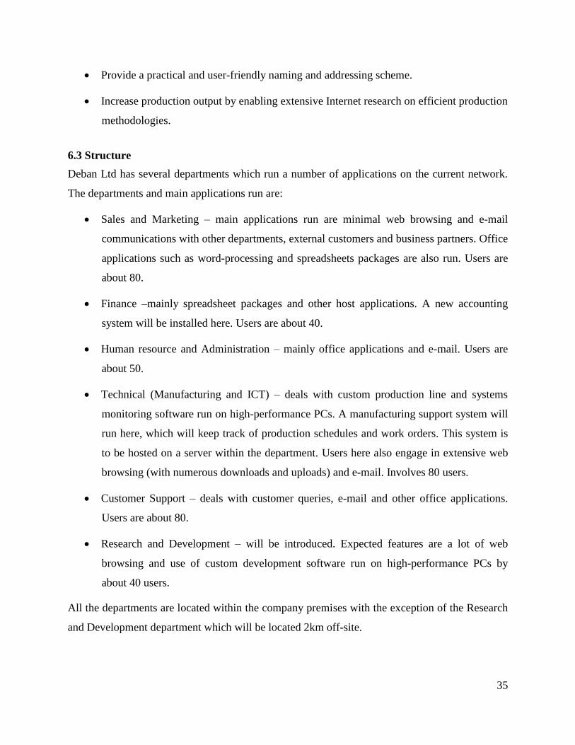
6.3 Structure
Deban Ltd has several departments which run a number of applications on the current network.
The departments and main applications run are:
Sales and Marketing – main applications run are minimal web browsing and e-mail
communications with other departments, external customers and business partners. Office
applications such as word-processing and spreadsheets packages are also run. Users are
about 80.
Finance –mainly spreadsheet packages and other host applications. A new accounting
system will be installed here. Users are about 40.
Human resource and Administration – mainly office applications and e-mail. Users are
about 50.
Technical (Manufacturing and ICT) – deals with custom production line and systems
monitoring software run on high-performance PCs. A manufacturing support system will
run here, which will keep track of production schedules and work orders. This system is
to be hosted on a server within the department. Users here also engage in extensive web
browsing (with numerous downloads and uploads) and e-mail. Involves 80 users.
Customer Support – deals with customer queries, e-mail and other office applications.
Users are about 80.
Research and Development – will be introduced. Expected features are a lot of web
browsing and use of custom development software run on high-performance PCs by
about 40 users.
All the departments are located within the company premises with the exception of the Research
and Development department which will be located 2km off-site.

36
Within the headquarters, one building hosts the Finance, Sales and Marketing, and Human
Resource and Administration departments while the Technical department is on a different
building. The Customer Support offices, where the reception area is, are housed within a
different building.
The Customer Support area should have wireless capability in which in-house staff, customers,
business partners, and generally any interested parties can access the company’s network.
6.4 Current Network
The current campus network is a hierarchical network architecture whereby a single router
provides Internet access (refer to Figure 6.1). The Internet link a 2Mbps link provided by a local
ISP.
Each department has an Ethernet switch (48-port) which connects all workstations, local printers
and servers via Category-5 UTP cables. These switches are all then connected via fiber optic
cables to a switch in the Technical Department, which is in turn connected to the router. All
these connections are based on 100 Mbps Ethernet.
Every department houses its file server and the Finance and Sales departments also house their
own database server.
A private addressing scheme is used whereby all network workstations are within a 192.168.5.0
subnet. A subnet mask of 255.255.255.0 is used. A DHCP server manages the addressing of all
PCs and a DNS does the naming. However, public servers such as the web server and e-mail
sever have public addresses.

37
Figure 6.1: Current Network Layout
6.4.1 Traffic flows
With the help of protocol analyzers and interaction with the users, traffic flows and loads were
analyzed. The applications, protocols and number of workstations were considered. General web
browsing and applications running Internet uploads was found to use up most of the bandwidth.
38
After observing bandwidth utilization on several links in a 10-minute window, the utilization on
the Ethernet links was found to be about 55%. The WAN link was found to have an average
utilization of about 78%, which was approaching saturation.
A large number of broadcasts was using up bandwidth in the network. Broadcast traffic
accounted for about 30% of all traffic on the campus network.
TCP/IP protocol is dominant throughout the network.
6.4.2 Inherent Problems of the Current Design:
All devices are within the same broadcast domain.
The Internet link and Ethernet links are overloaded.
The network has run out of IP addresses. Only 254 devices are allowed on the network,
according to the current addressing scheme.
There are difficulties in transmitting video and voice traffic due to minimal bandwidth
availability.
6.5 Proposed Design
After considering the existing network and the technical and business goals, a network design
was proposed.
6.5.1 Connectivity
Each building will have a wiring closet and each workstation will be connected to the wiring
closet in its respective building through Category-5 UTP cables. These wiring closets are
eventually connected to a computer center within the Technical department’s offices through
fiber optic cables.
All the user terminals have 100Mbps Fast Ethernet switched connections. Users in the Finance
and Human Resource and Administration departments are connected to 24-port switches at a
ratio of 20 users to a switch. Within the Sales department, 48-port switches are used with a
maximum of 40 terminals connected to a single switch. These departments require fewer
computing resources, thus will be allocated lower bandwidth compared to the Technical

39
department. The technical department’s users are connected to 24-port Fast Ethernet switches at
a ratio of 16 users to a switch. The Research and Development department also employs this
ratio.
The Finance, Human Resource and Administration and Sales departments each have their own
file servers, but other major servers used in the company are within the server farm located in the
Technical department. This server farm is connected to the backbone switch via a Gigabit
Ethernet link. Servers located here include the DNS, DHCP, Remote Access Server, RADIUS,
Proxy and database servers.
The Research and Development department is connected to the campus network via a wireless
point-to-point link.
Wireless access points are placed within the reception area in the Customer Support building.
These allow users to access the company’s public network.
6.5.2 Logical Network Design
Hierarchical network design has been used here.
At the core layer is the main router where the Internet link from the ISP terminates. There is a
dedicated firewall behind this router and a DMZ is created. Public servers are placed within the
DMZ.
A core switch is then placed behind a firewall to form the distribution layer. This is a layer 3
switch that forms the backbone of the enterprise network. It is from this switch that the different
departments of the enterprise are connected. The server farm is directly connected to the
backbone switch.
At the access layer, Ethernet switches are located at departmental offices to offer connectivity to
network terminals.
Several VLANs are configured in the network. These are:
The Sales and Marketing Department forms one VLAN.
The Finance department is placed in one VLAN.
Another VLAN is defined for the Administration department.

40
The Technical and Research and Development departments are placed in the same
VLAN.
Another VLAN is configured for the Customer Support Department.
Wireless users are placed a separate VLAN. Wireless access provides access to the
company’s public network only.
The layer 3 core switch performs inter-VLAN routing.
Addressing
The range of addresses used is 10.2.0.0 to 10.2.20.254, which is summarized as 10.2.0.0/16.
Each department is placed in its own subnet. A full Class C address is assigned to each
department as:
Technical – 10.2.1.0
Research and Development – 10.2.2.0
Finance – 10.2.3.0
Human Resource and Administration – 10.2.4.0
Sales and Marketing – 10.2.5.0
Customer Support – 10.2.6.0
The server farm is placed on 10.2.7.0/24 and remote users are incorporated in 10.2.8.0/24.
Users accessing the network via wireless capability are placed on a separate subnet: 10.2.9.0/24.
There is a public network segment which contains the external Web and FTP servers and has
been assigned legitimate public addresses. The firewall there ensures that traffic from the public
network subnet does not cross into the secured network, but the reverse is allowed.
A DHCP system is used to assign IP addresses to user terminals. DNS name management system
is also used. DHCP and DNS services are hosted within one server thus all the addresses and
names are centrally managed.
The strategy used in address assignment is:
• Servers use 10.2.n.1 to 10.2.n.20
• Printers use 10.2.n.21 to 10.2.n.39

41
• Users use 10.2.n.40 to 10.2.n.249
• Routers use 10.2.n.250 to 10.2.n.254
This strategy allows 210 hosts to be connected onto a single subnet. For instance, the block of
addresses for users in the Finance department is: 10.2.3.40 to 10.2.3.249. If a greater number of
hosts are required within a single subnet, a new Class C address can be assigned. This strategy
also ensures that devices such as printers and routers which require static IP addresses can be
assigned addresses without conflict with user terminals. The subnets for the printers, routers and
servers are not included in the DHCP.
Naming
A hierarchical naming system is implemented.
The domain name ‘deban.com’ is used as the root domain for this network. Sub-domains are
then defined for each department.
This is as shown:
• Technical – tech.deban.com
• Research and Development – rd.deban.com
• Finance – finance.deban.com
• Human Resource and Administration – admin.deban.com
• Sales and Marketing – sales.deban.com
• Customer Support – support.deban.com
Host machines are then named. These are named starting with pc1 for the first host, and
following an ascending order (pc2, pc3, pc4…pcn; n being an integer whose maximum value is
the number of user machines within a department). Therefore a host in the sales department can
have the name ‘pc8.sales.deban.com’. The DNS server manages this naming scheme.
Remote Access
Users can gain access of the company’s secure network from anywhere as long as they are
connected to the Internet. This is made possible by the implementation of VPNs. Such users are
placed on a separate subnet (10.2.8.0/24) to ease administration and management. Security is
paramount in such connections. The user names and passwords are encrypted and it is

42
recommended that they be changed every 30 days. The DHCP server assigns IP addresses to
these users.
A remote access server is included in the sever farm. A powerful PC running Ms Windows 2008
server suite is used. This also performs network address translation for connecting the private
network to the Internet and acts as an IP router for the VPN. VPN client software is installed on
client machines. The client software establishes the encrypted tunnel (a client-initiated remote
access model is used).
Traffic Flows
Following the analysis of traffic flows on the network, expected flows and loads were estimated,
including the new applications.
Main applications expected to run on Deban’s network are tabulated in Table 6.1
Table 6.1: Applications on the Network
Application Estimated
Transfer Size (Kb)
Departments using
application
Total number
of users
E-mail 100 All 390
Office applications (word-
processing, spreadsheets)
400 All 390
Manufacturing support 500 Technical 80
Production-line software 500 Technical 80
Customer query system 400 Customer Support 40
Web browsing 300 All 390
Development software 500 Research &
Development
40

43
The applications’ traffic was categorized as either general web access or video and voice traffic.
It was recommended that allocation of bandwidth be based on estimations of throughput for
these two traffic types as in Table 6.2.
Table 6.2: Estimated Traffic Throughput
Application Type Estimated Throughput
Web access 20Kbps
Video and Voice 64Kbps
The number of probable simultaneous users within each department was determined and thus the
bandwidth of the links computed as reflected in Table 6.3.
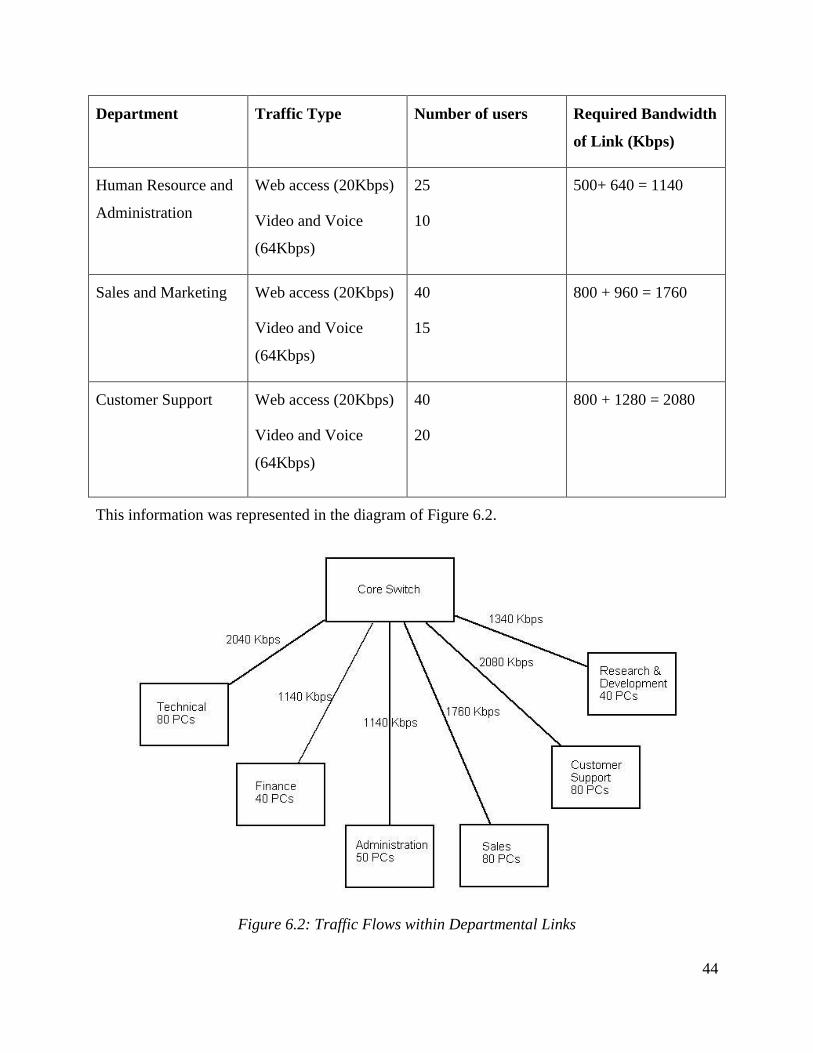
Table 6.3: Departmental Links
Department Traffic Type Number of users Required Bandwidth
of Link (Kbps)
Technical Web access (20Kbps)
Video and Voice
(64Kbps)
70
10
1400 + 640 = 2040
Research and
Development
Web access (20Kbps)
Video and Voice
(64Kbps)
35
10
700 + 640 = 1340
Finance Web access (20Kbps)
Video and Voice
(64Kbps)
25
10
500+ 640 = 1140
44
Department Traffic Type Number of users Required Bandwidth
of Link (Kbps)
Human Resource and
Administration
Web access (20Kbps)
Video and Voice
(64Kbps)
25
10
500+ 640 = 1140
Sales and Marketing Web access (20Kbps)
Video and Voice
(64Kbps)
40
15
800 + 960 = 1760
Customer Support Web access (20Kbps)
Video and Voice
(64Kbps)
40
20
800 + 1280 = 2080
This information was represented in the diagram of Figure 6.2.
Figure 6.2: Traffic Flows within Departmental Links

45
From the tabulated data the various links were provisioned. The conclusion was that to achieve
proper network performance, the links to the various departments be of bandwidth:
Technical – 3 Mbps
Research and Development – 2 Mbps
Finance – 1.2 Mbps
Human Resource and Administration – 1.2 Mbps
Sales and Marketing – 2 Mbps
Customer Support –2.5 Mbps
The deployment of 100 Mbps Ethernet ensures that the required throughput figures are
attainable.
Furthermore, it is estimated that the traffic flowing to and from the router that connects the
campus network to the Internet would be about 10 Mbps.
Therefore, a 12Mbps connection to the Internet was recommended via a reliable ISP.
Connection to the Internet
Internet connectivity plays an important role in the day-to-day running of Deban ltd. The router
within the Technical department’s building provides the point of connection to the Internet.
There is a dedicated firewall behind the router for security. This firewall appliance also performs
address translation. The NAT implemented here has port translation, thus all out-going traffic
from the network has one address. NAT provides for static addresses for the web and e-mail
servers.
The web services server (HTTP, FTP and e-mail), firewall and the primary DNS server obtain
public addresses from the ISP.
The domain ‘www.deban.com’ is registered with the relevant authorities.
OSPF is employed for routing and switching within the network as it provides load balancing
and it is not vendor-specific. Furthermore, TCP/IP protocol is employed throughout the network.
The logical network design is reflected in Figure 6.3.

46
Figure 6.3: Logical Network Design
6.5.3 Physical Network Design
Physical Media
• 100 Mbps Ethernet switches are used within buildings.

47
• Cat 5e UTP cables connect workstations to the switches. One building which
hosts the Finance, Sales and Administration departments has a cabling structure
as represented in Figure 6.4.
Figure 6.4: Building Network Architecture
• A centralized cabling scheme is employed whereby multimode fiber optic cables
run in underground conduits from the Networks Operation Centre in the
Technical Department (refer to figure 6.5). A pair of cables is used for every link
to provide redundancy. These multimode fiber optic cables are 62.5/125 duplex
type.
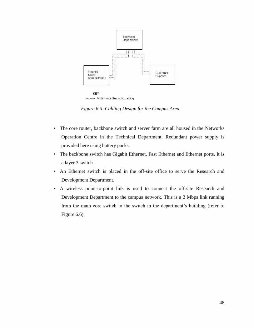
48
Figure 6.5: Cabling Design for the Campus Area
• The core router, backbone switch and server farm are all housed in the Networks
Operation Centre in the Technical Department. Redundant power supply is
provided here using battery packs.
• The backbone switch has Gigabit Ethernet, Fast Ethernet and Ethernet ports. It is
a layer 3 switch.
• An Ethernet switch is placed in the off-site office to serve the Research and
Development Department.
• A wireless point-to-point link is used to connect the off-site Research and
Development Department to the campus network. This is a 2 Mbps link running
from the main core switch to the switch in the department’s building (refer to
Figure 6.6).

49
Figure 6.6: Physical set-up showing the wireless link to the Research Department
The overall network set up is represented Figure 6.7.
Figure 6.7: Internetwork Diagram
50
6.5.4 Testing and Optimization
It is recommended that a prototype be built and deployed in the Technical Department. The
performance of the prototype can be analyzed by carrying out tests with the help of traffic
generators, protocol analyzers and QoS management tools. Industry tests such as NetPredictor’s
NetPredict can be employed.
It is important to configure RSVP on the router and core switch for of QoS analysis. Traffic
management should also be defined whereby delay-sensitive traffic flows (such as voice and
video) should be accorded higher priority. An appropriate queuing strategy, such as WFQ,
should be incorporated to optimize the network.
The network needs to be reliable and there should be no over-utilization of routers/switches and
links. Wireless access and remote access are expected to be secure and convenient. Wireless
users are able to access the company’s public network. Moreover, the company’s private
network is secured from outsiders, who can only access the public network.
The 12 Mbps Internet connection was found to be sufficient and appropriate to allow for growth.
VLANs on the network ensured security within the various subnets.
Recommendations
It is recommended that videoconferencing equipment be integrated within the network to enable
the enterprise enjoy the benefits of videoconferencing. This equipment includes Multi-point
Control Units (MCUs), gatekeepers and gateways.

51
6.6 Simulation Environment
A network was simulated using the Boson Netsim Simulation Environment. The Netsim network
simulator provides functionality for simulating network devices, protocols and switching
techniques and traffic flows. It provides a platform for simulating various LAN and WAN
topologies. Therefore, it was considered a suitable environment for the network designed.
Simulations carried out were:
(a) Overall Network Design
A network was designed in the Netsim Simulator. This network consisted of 6 departments
connected through switches to a core router. This is shown in the screenshot 6.1.
DB1 represents the router and SW1 the core switch. Departmental switches are named
Technical, Finance, Customer and RnD. Interfaces for devices were configured and IP
addresses assigned. This is reflected in the appendix.

52
For the router DB1, addresses for interfaces were Fast Ethernet: 10.2.1.251, Serial:
172.20.10.1. Different subnets were used for the different departments as follows: Technical:
10.2.1.n, Finance: 10.2.3.n, Administration: 10.2.4.n, Sales: 10.2.5.n, Customer Support:
10.2.6.n, and Research: 10.2.2.n.
The PCs in the various departments were assigned Class C addresses and the router set as the
default gateway. Several parameters were configured on the router including protocol, MTU,
bandwidth, delay and encapsulation. These configurations are reflected in the appendices.
Connectivity on the links was tested using tests such as ping and traceroute.
(b) VLANs
VLANs are configured at switch Finance and SW1. At switch Finance three VLANs are
configured for the three departments using the switch: Finance (PC3, PC4),
Administration (PC5, PC6) and Sales (PC7, PC8). These were VLANs V2, V3 and V4
respectively, and they ensured privacy of data for the three departments. Furthermore,
VLANs were also configured at SW1.
Tests were run from the PC interfaces and router interface to establish connectivity and
data flow.
A VPN was also configured to enable secure remote access. This was shown in the
simulator by configuring a tunnel through which access was established.
Results
It was established that connectivity to the router exists from each PC. For instance PC1
returned ping results:
Boson BOSS 5.0 IP Configuration
Ethernet adapter Local Area Connection:
IP Address. . . . . . . . . . . . : 10.2.1.60
Subnet Mask . . . . . . . . . . . : 255.255.255.0
Default Gateway . . . . . . . . . : 10.2.1.251
C:>ping 10.2.1.60
Pinging 10.2.1.60 with 32 bytes of data:

53
Ping statistics for 10.2.1.60: Packets: Sent = 5, Received = 5, Lost = 0 (0%
loss),
Approximate round trip times in milli-seconds:
Minimum = 50ms, Maximum = 60ms, Average = 55ms
From the router interface:
Welcome to the Boson NetSim!
Deb#show ip interface brief
Interface IP-Address OK? Method Status Protocol
Serial1/0 172.20.10.1 YES unset up down
Serial1/1 unassigned YES unset administratively down down
FastEthernet0/0 10.2.1.251 YES unset up up
Deb#ping 10.2.1.60
Type escape sequence to abort.
Sending 5, 100-byte ICMP Echos to 10.2.1.60, timeout is 2 seconds:
!!!!!
Success rate is 100 percent (5/5), round-trip min/avg/max = 1/2/4 ms.
Due to the VLAN configurations, workstations form the Finance department cannot access the
workstations from the Sales department. This was noted from the simulation as ping requests
returned ping negative. Each department was placed in its own VLAN so its data flows remained
private to the members of that department only.
Queuing was set on the router for optimization purposes.
Tunneling ensured that remote users were able to access the company’s network securely.

54
CHAPTER 7: CONCLUSIONS AND RECOMMENDATIONS
7.1 Conclusions
Internetwork design for a medium-level enterprise was successfully studied and a network
designed for Deban Ltd. The top-down methodology was found to be a suitable design
methodology whereby the design is tackled in a hierarchical manner.
Conformity to customer requirements was noted to be an important determinant in the process of
building appropriate network architecture.
7.2 Recommendations
Internetwork design can be further analyzed and more robust networks built to encompass more
features such as high-end videoconferencing and enterprise-wide and WAN IP telephony.

55
REFERENCES
[1] James D. McCabe, Network Analysis, Architecture, and Design, 3rd
Edition, Morgan
Kaufman Publishers, 2007.
[2] Priscilla Oppenheimer, Top-Down Network Design, 2nd Edition, Cisco Press, 2004.
[3] Martin W. Murhammer, Kok-Keong Lee, Payam Motallebi,
Paolo Borghi and Karl Wozabal, IP Network Design Guide, IBM, June 1999.
[4] Diane Teare, Catherine Paquet, Campus Network Design Fundamentals, Cisco Press, 2005.
[5] Mark A. Poplar, Inside Scoop to CCDA Certification, BeachFront Quizzer Inc.
Various web resources were also used:
[6] Shaun Hummel, Network Design Process - Effective Network Planning and Design, retrieved
from http://ezinearticles.com/?Network-Design-Process---Effective-Network-Planning-and-
Design&id=2348088.
[7] CCDA - Design Process Diagram - The Cisco Learning Network, retrieved from:
https://learningnetwork.cisco.com/message/80630.
[8] LAN Methodology: Local Area Network Design and Implementation Steps (2011), retrieved
form: http://hubpages.com/hub/Local-Area-Network-Design-and-Implementation.
[9] Routing and Remote Access (2011), retrieved from: http://technet.microsoft.com/en-
us/network/bb545655.

56
APPENDIX
Interface Configurations:
Router:
hostname Deb
ip subnet-zero
interface Serial1/0
ip address 172.20.10.1 255.255.255.0
no ip directed-broadcast
interface FastEthernet0/0
ip address 10.2.1.251 255.255.0.0
no ip directed-broadcast
ip ospf cost 1!
router ospf 100
network 10.2.0.0 0.0.0.255 area 0
network 172.20.0.0 0.0.255.255 area 0!
ip classless
no ip http server!
access-list 2 permit any!
queue-list 2 queue 1 byte-count 20000!
line con 0
transport input none
line aux 0
line vty 0 4!
no scheduler allocate …end
PCs:
PC1: interface Ethernet0
ip address 10.2.1.60 255.255.255.0

57
no ip directed-broadcast!
ip classless
no ip http server!
ip route 0.0.0.0 0.0.0.0 10.2.1.251.
PC3: interface Ethernet0
ip address 10.2.3.70 255.255.255.0
no ip directed-broadcast!
ip classless
no ip http server!
ip route 0.0.0.0 0.0.0.0 10.2.1.251
Some configuration commands entered for the router:
Deb(config)#router ospf 100 OSPF configuration
Deb(config-router)#network 10.2.0.0 0.0.0.255 area 0
Deb(config-router)#network 172.20.0.0 0.0.255.255 area 0
Deb(config-router)#exit
Deb(config)#exit
Deb#show ip route
Codes: C - connected, S - static, I - IGRP, R - RIP, M - mobile, B - BGP
D - EIGRP, EX - EIGRP external, O - OSPF, IA - OSPF inter area
E1 - OSPF external type 1, E2 - OSPF external type 2, E - EGP
i - IS-IS, L1 - IS-IS level-1, L2 - IS-IS level-2, * - candidate default
U - per-user static route
Gateway of last resort is not set
10.0.0.0/16 is subnetted, 1 subnets
C 10.2.0.0 is directly connected, FastEthernet0/0 describes the connected networks and
172.20.0.0/24 is subnetted, 1 subnets nature of connection
O 172.20.10.0 [110/64] via 172.20.10.1, 00:00:24, Serial1/0
Deb(config)#queue 2 queue 1 byte-count ? queuing defined with 20 Kb byte-count
<1-16777215> size in bytes
Deb(config)#queue 2 queue 1 byte-count 20000
Deb#show running-config
.
.
!queue-list 2 queue 1 byte-count 20000
Configuration commands for Switch Finance: Finance#vlan database
Finance(vlan)#vlan 2 name V2 VLAN V2 created
VLAN 2 added:
Name:V2

58
Finance(vlan)#vlan 3 name V3 VLAN V3 created
VLAN 3 added:
Name:V3
Finance(vlan)#exit
APPLY completed.
Exiting....
Finance#conf t
Enter configuration commands, one per line. End with CNTL/Z.
Finance(config)#int range fastethernet 0/2-3 PC3 & PC4 entered into VLAN V2
Finance(config-if-range)#switchport mode access
Finance(config-if-range)#switchport access vlan 2
Finance(config-if-range)#end
Finance#conf t
Enter configuration commands, one per line. End with CNTL/Z.
Finance(config)#int range fastethernet 0/4-5 PC5 & PC6 entered into VLAN V3
Finance(config-if-range)#switchport mode access
Finance(config-if-range)#switchport access vlan 3
Finance(config-if-range)#end
Finance#vlan database
Finance(vlan)#vlan 4 name V4 VLAN V4 created
VLAN 4 added:
Name:V4
Finance(vlan)#exit
APPLY completed.
Exiting....
Finance#conf t
Enter configuration commands, one per line. End with CNTL/Z.
Finance(config)#int range fastethernet 0/6-7 PC7 & PC8 entered into VLAN V4
Finance(config-if-range)#switchport mode access
Finance(config-if-range)#switchport access vlan 4
Finance(config-if-range)#end
Finance#show vlan
Finance#show vlan
VLAN Name Status Ports
---- -------------------------------- --------- -------------------------------
1 default active Fa0/1, Fa0/8, Fa0/9, Fa0/10 VLAN status: active VLANs and
Fa0/11, Fa0/12 corresponding switchports
2 V2 active Fa0/2, Fa0/3
3 V3 active Fa0/4, Fa0/5
30 pcs active
4 V4 active Fa0/6, Fa0/7
1002 fddi-default active
1003 token-ring-default active
1004 fddinet-default active
1005 trnet-default active
VLAN Type SAID MTU Parent RingNo BridgeNo Stp BrdgMode Trans1 Trans2
---- ----- ---------- ----- ------ ------ -------- ---- -------- ------ ------
1 enet 100001 1500 - - - - - 0 0 MTU = 1500b
2 enet 100002 1500 - - - - - 0 0
3 enet 100003 1500 - - - - - 0 0
30 enet 100030 1500 - - - - - 0 0
4 enet 100004 1500 - - - - - 0 0
1002 fddi 101002 1500 - - - - - 0 0

59
1003 tr 101003 1500 - - - - - 0 0
Finance#show vtp status
VTP Version : 2
Configuration Revision : 2
Maximum VLANs supported locally : 64
Number of existing VLANs : 9
VTP Operating Mode : Server
VTP Domain Name : bigdomain
VTP Pruning Mode : Disabled
VTP V2 Mode : Disabled
VTP Traps Generation : Disabled
MD5 digest : 0xEE 0xB3 0xDC 0x9F 0xE2 0xE0 0x25 0xDF
Configuration last modified by 0.0.0.0 at 3-1-93 04:55:57
Local updater ID is 0.0.0.0 (no valid interface found)
Finance(config)#vtp domain Mike
Changing VTP domain from NULL to mike Customization of VTP domain name
Finance(config)#exit
Finance#show vtp status
VTP Version : 2
Configuration Revision : 2
Maximum VLANs supported locally : 64
Number of existing VLANs : 9
VTP Operating Mode : Server VTP in sever mode to broadcast
VTP Domain Name : mike VLAN configurations
VTP Pruning Mode : Disabled
VTP V2 Mode : Disabled
VTP Traps Generation : Disabled
MD5 digest : 0xEE 0xB3 0xDC 0x9F 0xE2 0xE0 0x25 0xDF
Configuration last modified by 0.0.0.0 at 3-1-93 04:55:57
Local updater ID is 0.0.0.0 (no valid interface found)
Finance#show int fastethernet 0/2 switchport
Name: Fa0/2
Switchport: Enabled
Administrative mode: static access
Operational mode: static access
Administrative Trunking Encapsulation: dot1q
Negotiation of Trunking: On
Access Mode VLAN: 2 (V2)
Trunking Native Mode VLAN: 1 (default)
Trunking VLANs Enabled: ALL
Pruning VLANs Enabled: 2-1001
Protected: false
Voice vlan: none (Inactive)
Appliance trust: none