ENTERPRISE GRADE PROXIMITY BEACON WITH LONG AUTONOMY · WITH LONG AUTONOMY DESCRIPTION ... o...
14
DATASHEET Ɩ EMBE01 This is not the last page Copyright 2017, EM Microelectronic-Marin SA EMBE01-DS, Version 1.0, 9-Nov-17 1 www.emmicroelectronic.com 420005-A01, 3.0 ENTERPRISE GRADE PROXIMITY BEACON WITH LONG AUTONOMY DESCRIPTION EMBE01 is an enterprise grade Bluetooth TM v4.1 compatible proximity beacon. It is particularly suitable for mass deployment by system integrators in demanding environments thanks to long battery life and robust housing. It is part of the EM Microelectronic line of Bluetooth v4.1 beacon family. EMBE01 advertises ID data that is compatible with a variety of common beacon standards and connectable and non-connectable variants. The unit comes in an IP65 rated weatherproof enclosure, using 4 standard AA batteries for power (batteries not delivered with unit). A push-button and a magnetic reed switch provide respectively internal and external control, along with two LEDs for feedback to the user. EMBE01 is shipped pre-programmed supporting 6 common advertisement standards: Ɩ ID Data: Configurable UUID, Major ID, Minor ID, and Output power. iBeacon compatible technology Ɩ Alt Beacon : Configurable advertisement type, beacon ID, manufacture’s ID Ɩ Eddystone TM URL configurable URL Ɩ Eddystone TM UID configurable Namespace ID and Instance ID Ɩ Eddystone TM TLM Ɩ EM Sensor Beacon EMBE01 can be delivered in any quantity with guaranteed unique ID numbers. A unique serial number is printed on the label and encoded in a QR code for optical scanning. EMBE01 firmware can be customized for individual deployments with the Enterprise Beacon Development Kit. Complete source code and libraries are available through emdeveloper.com for registered customers. EMBE01 is FCC, IC, and CE certified, RoHS and REACH compliant. FEATURES Ɩ Rugged Weatherproof Enclosure o IP-65 rating, -40C to +60C operating range o Size: 100x80x28mm; Weight: 160g (w/o batteries) o Long autonomy and four replaceable AA batteries (not included) o Integrated push-button, magnetic reed switch o Red and green LED indicators visible through the casing o Wall Mount accessory Ɩ Bluetooth v4.1 Support, including: o Non-connectable advertisement o Connectable advertisement o Connection from an initiating central o GATT service support Ɩ Unique Identification o UUID: 699EBC80-E1F3-11E3-9A0F-0CF3EE3BC012 o Unique Major and Minor IDs (serialized) o Unique Serial Number o Serial number, Major/Minor ID embedded in QR Code for deployment Ɩ Firmware and Parameter Upgrades Over The Air o Custom GATT services & supporting app to update standard advertisement parameters of advertisements (enable, disable and configure all advertisement parameters) o Custom GATT service supporting full update of the application firmware and Bluetooth stack APPLICATIONS Ɩ Indoor Navigation Ɩ Item Tracking Ɩ Authorized Access Ɩ Digital enhancement of visual displays Ɩ Location Based Notification EM MICROELECTRONIC - MARIN SA
Transcript of ENTERPRISE GRADE PROXIMITY BEACON WITH LONG AUTONOMY · WITH LONG AUTONOMY DESCRIPTION ... o...

DATASHEET Ɩ EMBE01
This is not the last page
Copyright 2017, EM Microelectronic-Marin SA EMBE01-DS, Version 1.0, 9-Nov-17
1 www.emmicroelectronic.com
420005-A01, 3.0
ENTERPRISE GRADE PROXIMITY BEACON
WITH LONG AUTONOMY
DESCRIPTION
EMBE01 is an enterprise grade BluetoothTM v4.1 compatible proximity beacon. It is particularly suitable for mass deployment by system integrators in demanding environments thanks to long battery life and robust housing. It is part of the EM Microelectronic line of Bluetooth v4.1 beacon family. EMBE01 advertises ID data that is compatible with a variety of common beacon standards and connectable and non-connectable variants.
The unit comes in an IP65 rated weatherproof enclosure, using 4 standard AA batteries for power (batteries not delivered with unit). A push-button and a magnetic reed switch provide respectively internal and external control, along with two LEDs for feedback to the user.
EMBE01 is shipped pre-programmed supporting 6 common advertisement standards:
Ɩ ID Data: Configurable UUID, Major ID, Minor ID, and Output power. iBeacon compatible technology
Ɩ Alt Beacon : Configurable advertisement type, beacon ID, manufacture’s ID
Ɩ EddystoneTM URL configurable URL Ɩ EddystoneTM UID configurable Namespace ID and
Instance ID Ɩ EddystoneTM TLM Ɩ EM Sensor Beacon
EMBE01 can be delivered in any quantity with guaranteed unique ID numbers. A unique serial number is printed on the label and encoded in a QR code for optical scanning.
EMBE01 firmware can be customized for individual deployments with the Enterprise Beacon Development Kit. Complete source code and libraries are available through emdeveloper.com for registered customers.
EMBE01 is FCC, IC, and CE certified, RoHS and REACH compliant.
FEATURES
Ɩ Rugged Weatherproof Enclosure
o IP-65 rating, -40C to +60C operating range o Size: 100x80x28mm; Weight: 160g (w/o batteries) o Long autonomy and four replaceable AA batteries
(not included) o Integrated push-button, magnetic reed switch o Red and green LED indicators visible through the
casing o Wall Mount accessory
Ɩ Bluetooth v4.1 Support, including:
o Non-connectable advertisement o Connectable advertisement o Connection from an initiating central o GATT service support
Ɩ Unique Identification
o UUID: 699EBC80-E1F3-11E3-9A0F-0CF3EE3BC012
o Unique Major and Minor IDs (serialized) o Unique Serial Number o Serial number, Major/Minor ID embedded in QR
Code for deployment
Ɩ Firmware and Parameter Upgrades Over The Air
o Custom GATT services & supporting app to update standard advertisement parameters of advertisements (enable, disable and configure all advertisement parameters)
o Custom GATT service supporting full update of the application firmware and Bluetooth stack
APPLICATIONS
Ɩ Indoor Navigation Ɩ Item Tracking Ɩ Authorized Access Ɩ Digital enhancement of visual displays Ɩ Location Based Notification
EM MICROELECTRONIC - MARIN SA
DATASHEET Ɩ EMBE01
This is not the last page
Copyright 2017, EM Microelectronic-Marin SA EMBE01-DS, Version 1.0, 9-Nov-17
2 www.emmicroelectronic.com
420005-A01, 3.0
TABLE OF CONTENTS
1. Product Description .................................................................................................................................................................... 3
2. Environmental and Storage Conditions....................................................................................................................................... 4
3. Product Outline Dimensions ....................................................................................................................................................... 4
4. Mechanical .................................................................................................................................................................................. 5
4.1. Batteries ............................................................................................................................................................................... 5
4.2. Push Button .......................................................................................................................................................................... 5
4.3. Reed Switch ......................................................................................................................................................................... 6
4.4. LED ....................................................................................................................................................................................... 6
4.5. Screws .................................................................................................................................................................................. 6
4.6. Wall Mount ............................................................................................................................................................................ 7
4.7. Locking Screw ...................................................................................................................................................................... 7
5. Electrical ..................................................................................................................................................................................... 8
5.1. Handling Procedures and Absolute Maximum Ratings ......................................................................................................... 8
5.2. General Operating Conditions .............................................................................................................................................. 8
5.3. Electrical Characteristics ...................................................................................................................................................... 8
5.4. Safety Fuse ........................................................................................................................................................................ 10
5.5. Regulatory .......................................................................................................................................................................... 10
5.5.1. USA-FCC...................................................................................................................................................................... 10
5.5.2. Canada-IC .................................................................................................................................................................... 10
5.5.3. CE ................................................................................................................................................................................ 10
6. Firmware ................................................................................................................................................................................... 11
6.1. EMBE01 standard Application Space State Machine ......................................................................................................... 11
6.1.1. Self-Test State .............................................................................................................................................................. 11
6.1.2. General Application Space ........................................................................................................................................... 11
6.1.3. Advertisement Architecture........................................................................................................................................... 12
6.1.4. Real Time Clock ........................................................................................................................................................... 12
6.2. Packet Contents ................................................................................................................................................................. 12
7. Label ......................................................................................................................................................................................... 12
8. Packing and Labeling ............................................................................................................................................................... 12
9. Environmental Responsibility .................................................................................................................................................... 13
9.1. Restriction of Hazardous Substances (RoHS) .................................................................................................................... 13
9.2. REACH and SVHC List ....................................................................................................................................................... 13
9.3. Product Hardware Recycling (WEEE) ................................................................................................................................ 13
10. Ordering Information ............................................................................................................................................................... 14
11. Contact Information ................................................................................................................................................................ 14
12. Reference Documents ............................................................................................................................................................ 14
DATASHEET Ɩ EMBE01
This is not the last page
Copyright 2017, EM Microelectronic-Marin SA EMBE01-DS, Version 1.0, 9-Nov-17
3 www.emmicroelectronic.com
420005-A01, 3.0
1. PRODUCT DESCRIPTION
The EMBE01 is a Bluetooth v4.1, 2.4 GHz RF electronic beacon with proximity capability, compatible with most common beacon standards with a low cost design for mass production.
The EMBE01 expands EM’s smart beacon portfolio (EMBC01, EMBC02) by bringing in enterprise-grade performance. It is designed for using 4 AA batteries for high autonomy and comes with an IP65 housing for increased robustness in demanding environments.
Configurable Advertisement Features:
Various advertisements can be considered, with the configuration options defined below can be added to the device via a custom GATT service:
Ɩ Fixed content packet types – Including, but not limited to ID Data, Eddystone UID and URL Ɩ Sensor based packet types – Including, but not limited to EM Sensor Packets and Eddystone TLM packets Ɩ Signal output strength steps - Ranging from -18dBm to +4dBm with 8 configurable levels Ɩ Transmission Interval – Uniquely defined at 10ms accuracy to each packet defined Ɩ Connectable/Non-connectable Advertisements Ɩ Advertisement MAC Address
Long Battery Life:
Ɩ 4 Replaceable AA batteries (not included) Ɩ High autonomy
1.5 year battery life at 0dBm output power and 100ms advertisement interval for non-connectable advertisement
4 year battery life at 0dBm output power and 500ms advertisement interval for connectable advertisement
Normal Operating Conditions:
Ɩ -40 to +60 C Ɩ Weather proof (IP-65 rating)
Robust and Lightweight:
Ɩ Rugged Polycarbonate/Polyester alloy housing Ɩ Dimensions: 100x80x28mm Ɩ Weight: 160g (w/o batteries)
Certifications:
Ɩ Environmental: RoHS, REACH Ɩ RF: FCC, IC, CE Ɩ Mechanical:
IP65 waterproof rating according to IEC 60529. UL 94 V-0 flammability rated plastics
Compatible With:
Ɩ Bluetooth v4.1 Ready Devices Ɩ Most Common Beacon Standards and proprietary
formats
Included Hardware:
Ɩ A white, industrial grade polycarbonate/Polyester alloy plastic enclosure
Ɩ Internal push button for mode changes Ɩ Externally visible green and red LED for user feedback Ɩ A permanent label with a unique serial number and QR
Code Ɩ Magnetic reed relay to allow user control without
opening the case
Fully Customizable:
Ɩ Development kit available Ɩ Adjustable parameters
Packet type and contents, UIDs, beacon interval, power level all configurable
Parameters may be adjusted in firmware or through the provided custom GATT service
Ɩ Modifiable firmware available through EMDeveloper.com
Ɩ Custom GATT service provided for updating advertisement parameters
Ɩ Fully updatable firmware over the air (FOTA)
DATASHEET Ɩ EMBE01
This is not the last page
Copyright 2017, EM Microelectronic-Marin SA EMBE01-DS, Version 1.0, 9-Nov-17
4 www.emmicroelectronic.com
420005-A01, 3.0
2. ENVIRONMENTAL AND STORAGE CONDITIONS
The operating and storage conditions are listed in Table 1 Environmental and Storage Conditions.
PARAMETER UNIT/CONDITION
Module operating temperature and humidity range
-40°C to 60°C and 0 to 90% RH
Weatherproof Module can be used in outdoor conditions.
It is rated IP65 according to IEC 60529.
Module storage temperature and humidity range
Modules must be stored in original EM packing at Temp=25°C±10°C / RH≤70%.
Table 1 Environmental and Storage Conditions
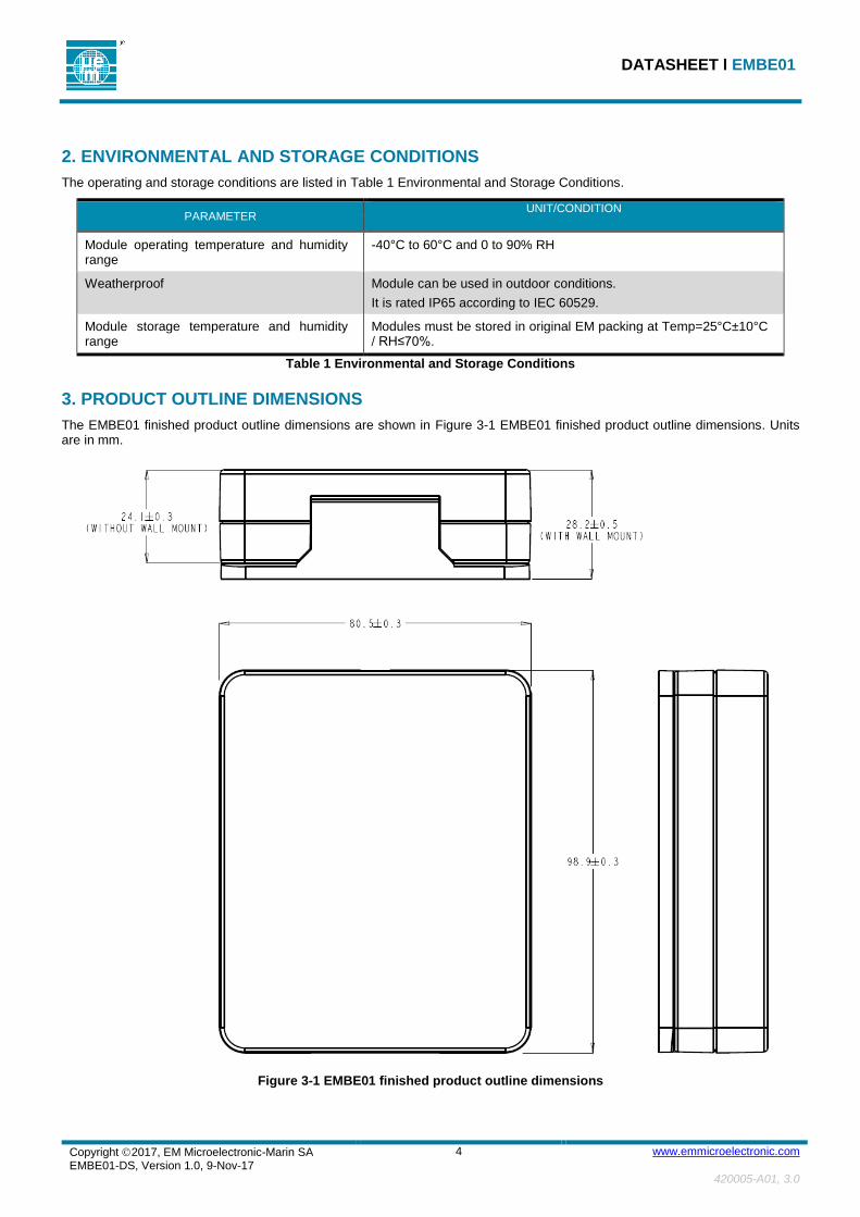
3. PRODUCT OUTLINE DIMENSIONS
The EMBE01 finished product outline dimensions are shown in Figure 3-1 EMBE01 finished product outline dimensions. Units are in mm.
Figure 3-1 EMBE01 finished product outline dimensions

DATASHEET Ɩ EMBE01
This is not the last page
Copyright 2017, EM Microelectronic-Marin SA EMBE01-DS, Version 1.0, 9-Nov-17
5 www.emmicroelectronic.com
420005-A01, 3.0
Figure 3-2 Exploded view of product
Figure 3-3 Exterior drawing of product
4. MECHANICAL
4.1. BATTERIES
The module is powered with 4 standard AA batteries. Batteries are not provided with the module.
Industrial grade batteries are recommended for installations. EM Microelectonic recommends Duracell Coppertop Alkaline batteries. Low grade batteries have an increased out-gassing at end of life that may result in oxidation and degrade performance of the electronics.
The following precautions should be observed to guarantee maximum performance.
Take care to fit batteries correctly, observing the ‘plus’ and ‘minus’ signs of the battery and module
Replace all four batteries simultaneously by fresh batteries of the same brand and type
Remove dead batteries from the module
Remove batteries from units that will not be used for extended periods of time
In case of a shock to the module, for example if dropped to the floor, it is possible that an intermittent power cut occurs, thus resetting the module firmware (See section 6.1). If this happens, please follow these steps:
1. Open the module and verify that all four batteries are properly held in the battery holders 2. Press the push button to reach the desired mode of operation 3. Close and reinstall the module
4.2. PUSH BUTTON
A tactile push button switch is accessible only from the inside of the case for enhanced security modes.
In the EMBE01 standard firmware, the switch is used to change modes.
Functions of the button can be modified via firmware modifications.

DATASHEET Ɩ EMBE01
This is not the last page
Copyright 2017, EM Microelectronic-Marin SA EMBE01-DS, Version 1.0, 9-Nov-17
6 www.emmicroelectronic.com
420005-A01, 3.0
4.3. REED SWITCH
The reed switch is activated when a magnet is placed near the indicated area of the case in Figure 4-1 Location of reed switch.
Figure 4-1 Location of reed switch
In the EMBE01 standard firmware, activation of the reed switch is used to enable the connectable advertisement for over-the-air updates to the advertisement settings or complete firmware.
Functions of the reed switch can be modified via firmware modifications using the distributed firmware.
4.4. LED
The green and red LEDs are visible through the plastic enclosure under indoor lighting conditions. LEDs are used to indicate the operating mode of the beacon.
Functions of the LED can be modified via firmware modifications.
4.5. SCREWS
The Front and Back housings are fastened with 4 thread forming screws for plastics, 3.63-1.34, 16mm length, Phillips head screws.
The 4 screws are delivered in a PE bag enclosed in the snap fitted housings.
Care should be taken when installing screws to make tight hold between front and back housings to retain the full IP rating. Installation of the device without using the screws will void the IP rating

DATASHEET Ɩ EMBE01
This is not the last page
Copyright 2017, EM Microelectronic-Marin SA EMBE01-DS, Version 1.0, 9-Nov-17
7 www.emmicroelectronic.com
420005-A01, 3.0
4.6. WALL MOUNT
The module is delivered with a Wall Mount accessory snap-fitted with the 2 housings. Outline dimensions and screw locations are shown in Figure 4-2 Wall Mount screw locations.
Figure 4-2 Wall Mount screw locations
4.7. LOCKING SCREW
The module can be securely fastened to the Wall Mount accessory with a locking screw (thread forming screws for plastics, 3.63-1.34, 15.9mm length), Philips drive #1.
This screw is included in the PE bag of screws for sealing the device.

DATASHEET Ɩ EMBE01
This is not the last page
Copyright 2017, EM Microelectronic-Marin SA EMBE01-DS, Version 1.0, 9-Nov-17
8 www.emmicroelectronic.com
420005-A01, 3.0
5. ELECTRICAL
Typical values are stated at room temperature (T=25oC) with a supply voltage of VCC=3.0V.
5.1. HANDLING PROCEDURES AND ABSOLUTE MAXIMUM RATINGS
This device has built-in protection against high static voltages or electric fields; however, anti-static precautions must be taken as with any CMOS components. Unless otherwise specified, proper operation can only occur when all terminal voltages are kept within the specified voltage range. The absolute maximum ratings of EMBE01 are listed in Table 2 Absolute Maximum Ratings.
PARAMETER MIN MAX UNIT
Supply Voltage VCC - VSS -0.3 3.8 V
Table 2 Absolute Maximum Ratings
Stresses above these listed maximum ratings may cause permanent damage to the device. Exposure beyond specified operating conditions may affect device reliability or cause malfunction
5.2. GENERAL OPERATING CONDITIONS
The general operating conditions of EMBE01 are listed in Table 3 General Operating Conditions.
PARAMETER MIN TYP MAX UNIT
Supply Voltage (VCC) 2.0 3.0 3.6 V Temperature range -40 25 +60 °C
Table 3 General Operating Conditions
5.3. ELECTRICAL CHARACTERISTICS
The electrical characteristics of EMBE01 are given in Table 4 Advertisement Energy per Advertisement. Data from this table can be used to extrapolate battery lifetime calculations in a user defined installation. Data from Table 5 Battery Life Estimations2 is extrapolated from the measured data of Table 4 Advertisement Energy per Advertisement using the equation provided. Unless otherwise specified: VCC=3.0V, T=25°C
Operating Mode Specification Typ Unit
Sleep Mode Average Current 2.5 µA Non-Connectable Advertisement Transmission Time 7 ms Energy Per Advert. (+4dBm) 11.2 nAh Avg Curr During Advert. (+4dBm) 5.7 mA Energy Per Advert. (0dBm) 10.0 nAh Avg Curr During Advert. (0dBm) 5.1 mA Energy Per Advert. (-18dBm) 8.6 nAh Avg Curr During Advert. (-18dBm) 4.4 mA Connectable Advertisement Transmission Time 15.6 ms Energy Per Advert. (+4dBm) 17.5 nAh Avg Curr During Advert. (+4dBm) 4.0 mA Energy Per Advert. (0dBm) 16.6 nAh Avg Curr During Advert. (0dBm) 3.8 mA Energy Per Advert. (-18dBm) 15.6 nAh Avg Curr During Advert. (-18dBm) 3.6 mA
Table 4 Advertisement Energy per Advertisement

DATASHEET Ɩ EMBE01
This is not the last page
Copyright 2017, EM Microelectronic-Marin SA EMBE01-DS, Version 1.0, 9-Nov-17
9 www.emmicroelectronic.com
420005-A01, 3.0
Common figures for battery lifetime are provided in Table 5 Battery Life Estimations2. Data is calculated from the measured data of Table 4 Advertisement Energy per Advertisement.
𝐵𝑎𝑡𝑡𝑒𝑟𝑦𝐿𝑖𝑓𝑒𝑡𝑖𝑚𝑒(ℎ𝑟) =𝐵𝑎𝑡𝑡𝑒𝑟𝑦𝐶𝑎𝑝𝑎𝑐𝑖𝑡𝑦(𝑚𝐴ℎ)
∑𝑆𝑙𝑜𝑡𝐴𝑣𝑒𝑟𝑎𝑔𝑒𝐶𝑢𝑟𝑟𝑒𝑛𝑡
𝑆𝑙𝑜𝑡𝐴𝑣𝑒𝑟𝑎𝑔𝑒𝐶𝑢𝑟𝑟𝑒𝑛𝑡 = 𝑆𝑙𝑒𝑒𝑝𝐶𝑢𝑟𝑟𝑒𝑛𝑡(𝑚𝐴) ∗𝐼𝑛𝑡𝑒𝑟𝑣𝑎𝑙 − 𝑇𝑟𝑎𝑛𝑠𝑚𝑖𝑠𝑠𝑖𝑜𝑛𝑇𝑖𝑚𝑒
𝐼𝑛𝑡𝑒𝑟𝑣𝑎𝑙 + 𝐴𝑣𝑔𝐴𝑑𝑣𝑒𝑟𝑡𝐶𝑢𝑟𝑟𝑒𝑛𝑡(𝑚𝐴) ∗
𝑇𝑟𝑎𝑛𝑠𝑚𝑖𝑠𝑠𝑖𝑜𝑛𝑇𝑖𝑚𝑒
𝐼𝑛𝑡𝑒𝑟𝑣𝑎𝑙
For example,
An Eddystone UID (NonConn) event was enabled at a 250ms interval and 0dBm
An IDData event (NonConn) was enable at 50ms and -18dBm
An EMEntOTA (Conn) event was enabled with a 375ms interval and +4dBm
𝑬𝑺𝑼𝑰𝑫 𝑨𝒗𝒈𝑪𝒖𝒓𝒓 = 2.5µ𝐴 ∗ 250𝑚𝑠 − 7𝑚𝑠
250𝑚𝑠+ 5.1𝑚𝐴 ∗
7𝑚𝑠
250𝑚𝑠 = 0.14𝑚𝐴
𝑰𝑫𝑫𝒂𝒕𝒆 𝑨𝒗𝒈𝑪𝒖𝒓𝒓 = 2.5µ𝐴 ∗ 50𝑚𝑠 − 7𝑚𝑠
50𝑚𝑠+ 4.3𝑚𝐴 ∗
7𝑚𝑠
50𝑚𝑠= 0.60𝑚𝐴
𝑬𝑴𝑬𝒏𝒕𝑶𝑻𝑨 𝑨𝒗𝒈𝑪𝒖𝒓𝒓 = 2.5µ𝐴 ∗ 375𝑚𝑠 − 15.6𝑚𝑠
375𝑚𝑠+ 4𝑚𝐴 ∗
15.6𝑚𝑠
375𝑚𝑠= 0.16𝑚𝐴
𝑨𝒗𝒈𝑪𝒖𝒓𝒓𝒆𝒏𝒕 = 𝐸𝑀𝐸𝑛𝑡𝑂𝑇𝐴 𝐴𝑣𝑔𝐶𝑢𝑟𝑟 + 𝐸𝑆𝑈𝐼𝐷 𝐴𝑣𝑔𝐶𝑢𝑟𝑟 + 𝐼𝐷𝐷𝑎𝑡𝑒 𝐴𝑣𝑔𝐶𝑢𝑟𝑟 = 0.9𝑚𝐴
𝑩𝒂𝒕𝒕𝒆𝒓𝒚𝑳𝒊𝒇𝒆(𝒉𝒓) = 4400𝑚𝐴ℎ
0.9𝑚𝐴= 4888ℎ𝑟𝑠 = 7 𝑚𝑜𝑛𝑡ℎ𝑠
Operating Mode Specification Typ Unit
Non-Connectable Advertisement +4dBm @ 100ms 15 month +4dBm @ 500ms 743 month 0dBm @ 100ms 17 month 0dBm @ 500ms 823 month -18dBm @ 100ms 20 month -18dBm @ 500ms 953 month
Connectable Advertisement +4dBm @ 100ms 9.8 month +4dBm @ 500ms 483 month 0dBm @ 100ms 10.3 month 0dBm @ 500ms 503 month -18dBm @ 100ms 10.8 month -18dBm @ 500ms 533 month
Table 5 Battery Life Estimations2
Range of the beacon is measured in an anechoic chamber in continuous modulation mode with a calibrated reference antenna. Measurements are taken across the three advertisement channels and min, max and average range is calculated from these

DATASHEET Ɩ EMBE01
This is not the last page
Copyright 2017, EM Microelectronic-Marin SA EMBE01-DS, Version 1.0, 9-Nov-17
10 www.emmicroelectronic.com
420005-A01, 3.0
measurements and reflected in Table 6 Open Air Range4 assuming a receiver with sensitivity of -90dBm. Range in specific installations will vary based on the environment and receiver used.
Operating Mode Specification Typ Unit
Output Power 4dBm Measured output power at 1m -61 dBm Calculated range for -95dBm at receiver 90 m Output Power 2dBm Measured output power at 1m -63 dBm Calculated range for -95dBm at receiver 60 m Output Power 0dBm Measured output power at 1m -65 dBm Calculated range for -95dBm at receiver 50 m Output Power -3dBm Measured output power at 1m -68 dBm Calculated range for -95dBm at receiver 30 m Output Power -9dBm Measured output power at 1m -72 dBm Calculated range for -95dBm at receiver 15 m Output Power -12dBm Measured output power at 1m -74 dBm Calculated range for -95dBm at reliever 12 m Output Power -15dBm Measured output power at 1m -79 dBm Calculated range for -95dBm at receiver 6 m Output Power -18dBm Measured output power at 1m -82 dBm Calculated range for -95dBm at receiver 4 M
Table 6 Open Air Range4
Note 1: Beacon interval is the Bluetooth advertising interval (advInterval) as defined in the Bluetooth Specification V4.0, Volume 6, Part B, Section 4.4.2.2.
Note 2: Battery Lifetime is calculated data based from measured data generated using equations provided
Note 3: Typical manufactures limit for AA batteries are 7 year shelf life or 84 months and may reduce battery lifetime from calculated values.
Note 4: Actual range can be impacted by alternate receiver sensitivities and non-open air environments.
5.4. SAFETY FUSE
To prevent excessive heating of the module in case of an electrical defect, a safety fuse is inserted between the batteries and the active circuits. In case of a non-functional module, first replace the batteries and check the LED status after pressing the push button. If the module still does not operate, please return the failing unit, using the EM customer return policy described on the EM Microelectronic site: www.emmicroelectronic.com/policies.
5.5. REGULATORY
EMBE01 complies with the following regulatory requirements:
5.5.1. USA-FCC
Ɩ Listed as 2ACQR-EMBE01 Ɩ Ɩ Part 15 – General emissions Ɩ Part 15.247:2011 – Operation within the band 2.4-2.4835GHz Ɩ Parts 15.205 and 15.209 – Spurious emissions
5.5.2. CANADA-IC
Ɩ Listed as 12155A-EMBE01 Ɩ Ɩ ICES-003 – General emissions Ɩ RSS-210:2010 – Low-power License exempt Radio Communication Devices
5.5.3. CE
Ɩ Radio Equipment Directive RED 2014/53/EU Ɩ Ɩ The Declaration of Conformity can be obtained from EM Microelectronic
DATASHEET Ɩ EMBE01
This is not the last page
Copyright 2017, EM Microelectronic-Marin SA EMBE01-DS, Version 1.0, 9-Nov-17
11 www.emmicroelectronic.com
420005-A01, 3.0
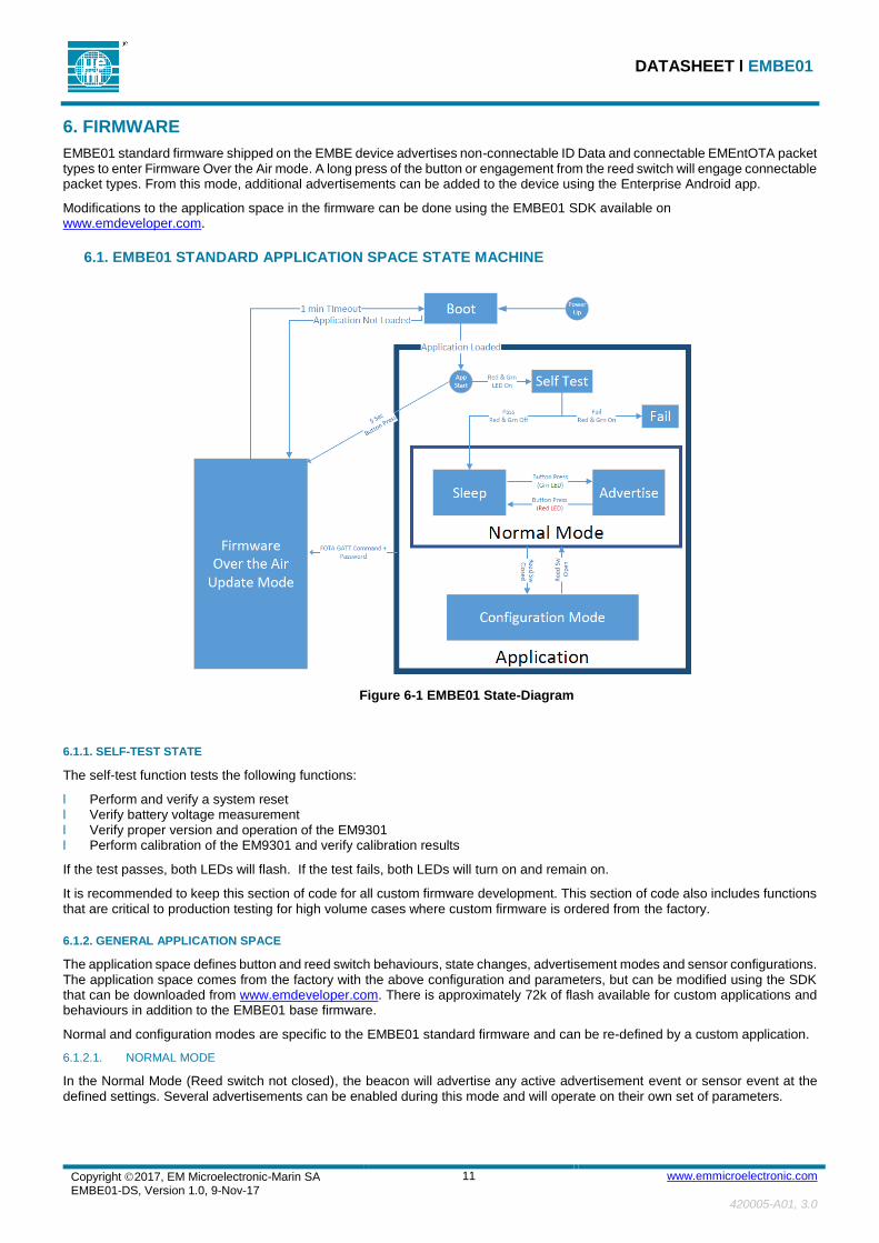
6. FIRMWARE
EMBE01 standard firmware shipped on the EMBE device advertises non-connectable ID Data and connectable EMEntOTA packet types to enter Firmware Over the Air mode. A long press of the button or engagement from the reed switch will engage connectable packet types. From this mode, additional advertisements can be added to the device using the Enterprise Android app.
Modifications to the application space in the firmware can be done using the EMBE01 SDK available on www.emdeveloper.com.
6.1. EMBE01 STANDARD APPLICATION SPACE STATE MACHINE
Figure 6-1 EMBE01 State-Diagram
6.1.1. SELF-TEST STATE
The self-test function tests the following functions:
Ɩ Perform and verify a system reset Ɩ Verify battery voltage measurement Ɩ Verify proper version and operation of the EM9301 Ɩ Perform calibration of the EM9301 and verify calibration results
If the test passes, both LEDs will flash. If the test fails, both LEDs will turn on and remain on.
It is recommended to keep this section of code for all custom firmware development. This section of code also includes functions that are critical to production testing for high volume cases where custom firmware is ordered from the factory.
6.1.2. GENERAL APPLICATION SPACE
The application space defines button and reed switch behaviours, state changes, advertisement modes and sensor configurations. The application space comes from the factory with the above configuration and parameters, but can be modified using the SDK that can be downloaded from www.emdeveloper.com. There is approximately 72k of flash available for custom applications and behaviours in addition to the EMBE01 base firmware.
Normal and configuration modes are specific to the EMBE01 standard firmware and can be re-defined by a custom application.
6.1.2.1. NORMAL MODE
In the Normal Mode (Reed switch not closed), the beacon will advertise any active advertisement event or sensor event at the defined settings. Several advertisements can be enabled during this mode and will operate on their own set of parameters.

DATASHEET Ɩ EMBE01
This is not the last page
Copyright 2017, EM Microelectronic-Marin SA EMBE01-DS, Version 1.0, 9-Nov-17
12 www.emmicroelectronic.com
420005-A01, 3.0
6.1.2.2. CONFIGURATION MODE
In Configuration Mode, all advertisements are disabled except for a single event that is reserved for the custom EMEntOTA connectable advertisement. This operating mode is intended to allow site operators to make the beacon connectable and configurable without opening the case, but also without requiring connectable advertisements to be sent when an operator is not present, as an added security measure.
6.1.3. ADVERTISEMENT ARCHITECTURE
The EMBE01 is capable of handling a variety of advertisements, each having a unique set of parameters, and the following properties may be configured:
Ɩ Fixed content packet types – Including, but not limited to ID Data, Eddystone URL and Eddystone UID Ɩ Sensor based packet types – Including, but not limited to EM Sensor Packets and Eddystone TLM Ɩ Signal output strength steps - Ranging from -18dBm to +4dBm with 8 configurable levels Ɩ Transmission Interval – Period at which to transmit the advertisement. 10ms accuracy Ɩ Connectable/Non-connectable Advertisement which describe a device which can be connected to or a device which cannot
be connected to. Ɩ MAC address – MAC address of the specific advertisement can be set. Note changing the MAC address to anything other
than the default address used at the factory means that the address cannot be guaranteed by EM to be unique in the installation area.
6.1.4. REAL TIME CLOCK
A real time clock is available from the microcontroller with an accuracy of 150ppm. The EMBE01 standard firmware uses this clock for timing of the advertisements. It can be modified to add a service for synchronizing this clock with an external clock.
6.2. PACKET CONTENTS
The Bluetooth advertising packets are undirected advertising events which follow the GAP specification according to the Bluetooth Specification V4.0, Volume 3, Part C, Section 11.
Packets follow the definitions defined in the Beacon Packet Definition Specification.
7. LABEL
The label is installed inside the front housing and has the following contents:
Ɩ Model: EMBE01 Ɩ Unique Serial Number Ɩ FCC-ID: 2ACQR-EMBE01 Ɩ IC ID: 12155A-EMBE01 Ɩ FCC and CE Marking Ɩ Major ID/Minor ID Ɩ EM Microelectronic company name Ɩ QR Code containing the unique Serial Number/Major ID/Minor ID
The serial number is generated by reading the device address of EMBE01, reversing the byte order, and printing the number in decimal form. For example:
Ɩ Device Address: 0x0CF3EE5A0001 corresponds to Serial Number: 001101037237004
8. PACKING AND LABELING
EMBE01 beacons are sorted in cardboard box with cardboard separators
Ɩ There are two levels of 30 parts in one box for the total of 60 parts per box. Ɩ Box size = 44.4 x 34.2 x 26.0 cm (L x W x H).
A label is applied on each box. The minimum information on the label is the following:
EM P/N:
Mfg date:
Module Lot Nr:
Qty:
Weight:

DATASHEET Ɩ EMBE01
This is not the last page
Copyright 2017, EM Microelectronic-Marin SA EMBE01-DS, Version 1.0, 9-Nov-17
13 www.emmicroelectronic.com
420005-A01, 3.0
9. ENVIRONMENTAL RESPONSIBILITY
9.1. RESTRICTION OF HAZARDOUS SUBSTANCES (ROHS)
EMBE01 (EM Product) is compliant with the EU RoHS Directive 2015/863/EU (European Directive on the Restriction of the Use of Certain Hazardous
Substances in Electrical and Electronic Equipment). Substances under ban (2015/863/EU) must not exceed the following values:
Ɩ Lead (Pb): <1000 ppm Ɩ Mercury (Hg): <1000 ppm Ɩ Cadmium (Cd): <100 ppm Ɩ Hexavalent Chromium (Cr VI) <1000 ppm Ɩ Polybrominated Biphenyls (PBB): <1000 ppm Ɩ Polybrominated Diphenyl Ethers (PBDE): <1000 ppm Ɩ Bis(2-ethylhexyl) Phthalate (DEHP) : <1000 ppm Ɩ Butyl benzyl Phthalate (BBP): <1000 ppm Ɩ Dibutyl Phthalate (DBP): <1000 ppm Ɩ Diisobutyl Phthalate (DIBP): <1000 ppm
9.2. REACH AND SVHC LIST
EM Product is compliant with the EU Regulation 1907/2006 (REACH) and the SVHC list (Substances of Very High Concern). The SVHC must be below the limit of 0.1% set by REACH Article 33, as specified in the Candidate list published by ECHA (European Chemical Agency) at
https://www.echa.europa.eu/web/guest/candidate-list-table
EM Product is compliant with the restrictions imposed by the 76/769/EEC European Directive and which have been included in the Annex XVII of REACH.
9.3. PRODUCT HARDWARE RECYCLING (WEEE)
The Directive 2012/19/EU on Waste Electrical and Electronic Equipment (WEEE) aims to reduce the waste arising from electrical and electronic equipment, and improve the environmental performance of everything involved in the life cycle of electrical and electronic equipment.
Instructions for Disposal of Waste Equipment by Users in Private Households
This symbol on the product or on its packaging indicates that this product must not be disposed of with your other household waste. Inappropriate disposal may be harmful. Instead, it is your responsibility to dispose of your waste equipment by handing it over to a designated collection point for the recycling of waste electrical and electronic equipment. The separate collection and recycling of your waste equipment at the time of disposal will help to conserve natural resources and ensure that it is recycled in a manner that protects human health and the environment. For more information about where you can drop off your waste equipment for recycling, please contact your local city office, your household waste disposal service or the sales point where you purchased the product.
Responsibilities
EM is committed to meeting the requirements of the European Union’s WEEE Directive.
However, the System Integrator of EM Product has the responsibility for the collection and recycling of the Beacon after its end of life.
EM Customer can send back the collected EM Product to EM at DAP conditions (Delivery at Place), after removing the batteries.
Specifics on battery
The Directive 2012/19/EU does apply to batteries and requires their removal from the electronic equipment and their separate collection. Once removed from equipment, used batteries are governed by the Batteries Directive 2006/66/EC.

DATASHEET Ɩ EMBE01
EM Microelectronic-Marin SA (“EM”) makes no warranties for the use of EM products, other than those expressly contained in EM's applicable General Terms of Sale, located at http://www.emmicroelectronic.com. EM assumes no responsibility for any errors which may have crept into this document, reserves the right to change devices or specifications detailed herein at any time without notice, and does not make any commitment to update the information contained herein.
No licenses to patents or other intellectual property rights of EM are granted in connection with the sale of EM products, neither expressly nor implicitly.
In respect of the intended use of EM products by customer, customer is solely responsible for observing existing patents and other intellectual property rights of third parties and for obtaining, as the case may be, the necessary licenses.
Important note: The use of EM products as components in medical devices and/or medical applications, including but not limited to, safety and life supporting systems, where malfunction of such EM products might result in damage to and/or injury or death of persons is expressly prohibited, as EM products are neither destined nor qualified for use as components in such medical devices and/or medical applications. The prohibited use of EM products in such medical devices and/or medical applications is exclusively at the risk of the customer.
Copyright 2017, EM Microelectronic-Marin SA EMBE01-DS, Version 1.0, 9-Nov-17
14 www.emmicroelectronic.com
420005-A01, 3.0
10. ORDERING INFORMATION
The EMBE01 is available as a finished product in a plastic housing with full FCC, IC, and CE certification. Pre-certification beacons are available for evaluation and development. The EMBE01 Beacon Development Kit is available with 5 pre-certification beacons, an interface board, and cable that is compatible with the 100-mil 20 pin connector of the ARM SWD Debug adapter. The EMBE01 ordering information and the order numbers are shown in Figure 10-1 EMBE01 Ordering Information
EMBE01 - F002 H1000
Base Part Number
Housing Version:
H1000: no logo Other: Assigned by EM
Accessory Code:
Firmware Version:
EVK: Evaluation kit F002: Proximity Beacon Version Other: Assigned by EM
Figure 10-1 EMBE01 Ordering Information
ORDER NUMBER DESCRIPTION CONTAINER UNITS PER CONTAINER
MINIMUM ORDER QUANTITY
EMBE01EVK Enterprise beacon, natural, evaluation samples Individual 1 1
EMBE01-F002-H1000 Enterprise beacon, Proximity beacon version, batteries not included
Box 60 60
EMBC01DVK
Proximity beacon Development Kit, includes 1 beacons + programming cable. ARM programmer and batteries not included.
Box 1 1
Table 7 EMBE01 Related Order Numbers
11. CONTACT INFORMATION Inquiries for lead-times, quotes, orders:
12. REFERENCE DOCUMENTS
EM9301 Data Sheet
Bluetooth Specification V4.0
Proximity Beacon Specification Release R1 Draft D