Enterprise Architect User Guidesparxsystems.com/downloads/resources/booklets/uml_dictionary.pdfThe...
261
Copyright © 1998-2010 Sparx Systems Pty Ltd UML Dictionary Enterprise Architect is an intuitive, flexible and powerful UML analysis and design tool for building robust and maintainable software. This dictionary explains the way in which Enterprise Architect represents the UML 2.1 diagrams, elements and connectors, and its own extensions of UML.
Transcript of Enterprise Architect User Guidesparxsystems.com/downloads/resources/booklets/uml_dictionary.pdfThe...

Copyright © 1998-2010 Sparx Systems Pty Ltd
UML Dictionary
Enterprise Architect is an intuitive, flexible and powerful UMLanalysis and design tool for building robust and maintainable
software.
This dictionary explains the way in which Enterprise Architectrepresents the UML 2.1 diagrams, elements and connectors, and
its own extensions of UML.

All rights reserved. No parts of this work may be reproduced in any form or by any means - graphic, electronic, ormechanical, including photocopying, recording, taping, or information storage and retrieval systems - without thewritten permission of the publisher.
Products that are referred to in this document may be either trademarks and/or registered trademarks of therespective owners. The publisher and the author make no claim to these trademarks.
While every precaution has been taken in the preparation of this document, the publisher and the author assume noresponsibility for errors or omissions, or for damages resulting from the use of information contained in this documentor from the use of programs and source code that may accompany it. In no event shall the publisher and the author beliable for any loss of profit or any other commercial damage caused or alleged to have been caused directly orindirectly by this document.
Printed: May 2010
Enterprise Architect - UML Dictionary
© 1998-2010 Sparx Systems Pty Ltd
PublisherSpecial thanks to:
All the people who have contributed suggestions, examples, bugreports and assistance in the development of Enterprise Architect.The task of developing and maintaining this tool has been greatlyenhanced by their contribution.Managing Editor
Technical Editors
Sparx Systems
Geoffrey Sparks
Geoffrey Sparks
Neil Capey

IContents
© 1998-2010 Sparx Systems Pty Ltd
Table of Contents
Foreword 1
UML Dictionary 2
................................................................................................................................... 4UML Diagrams
.......................................................................................................................................................... 4Behavioral Diagrams
......................................................................................................................................................... 5Activity Diagram
......................................................................................................................................................... 7Use Case Diagram
......................................................................................................................................................... 9State Machine Diagrams
......................................................................................................................................... 12Regions
......................................................................................................................................... 13Pseudo-States
......................................................................................................................................................... 14State Machine Table
......................................................................................................................................... 15State Machine Table Options
......................................................................................................................................... 17State Machine Table Operations
................................................................................................................................... 18Change State Machine Table Position
................................................................................................................................... 18Change State Machine Table Size
................................................................................................................................... 18Insert New State
................................................................................................................................... 19Insert Trigger
................................................................................................................................... 19Insert/Change Transition
................................................................................................................................... 20Reposition State or Trigger Cells
................................................................................................................................... 20Add Legend
................................................................................................................................... 20Find Cell in State Machine Diagram
................................................................................................................................... 21State Machine Table Conventions
................................................................................................................................... 21Export State Table To CSV File
......................................................................................................................................................... 22Timing Diagram
......................................................................................................................................... 23Create a Timing Diagram
......................................................................................................................................... 23Set a Time Range
......................................................................................................................................... 24Edit a Timing Diagram
................................................................................................................................... 24Add and Edit State Lifeline
................................................................................................................................... 25Edit States In State Lifeline
................................................................................................................................... 26Edit Transitions In State Lifeline
................................................................................................................................... 27Add and Edit Value Lifeline
................................................................................................................................... 28Add States In Value Lifeline
................................................................................................................................... 28Edit Transitions In Value Lifeline
................................................................................................................................... 29Configure Timeline - States
................................................................................................................................... 31Configure Timeline - Transitions
......................................................................................................................................... 32Time Intervals
................................................................................................................................... 36Time Interval Operations
......................................................................................................................................................... 39Sequence Diagram
......................................................................................................................................... 41Denote Lifecycle of an Element
......................................................................................................................................... 42Layout of Sequence Diagrams
......................................................................................................................................... 43Sequence Elements
......................................................................................................................................... 44Sequence Diagrams and Version Control
......................................................................................................................................... 45Sequence Element Activation
......................................................................................................................................... 46Lifeline Activation Levels
......................................................................................................................................... 48Sequence Message Label Visibility
......................................................................................................................................... 48Change the Top Margin
......................................................................................................................................... 49Inline Sequence Elements
......................................................................................................................................................... 49Communication Diagram
......................................................................................................................................... 51Communication Diagrams in Color
......................................................................................................................................................... 52Interaction Overview Diagram
.......................................................................................................................................................... 54Structural Diagrams
......................................................................................................................................................... 55Package Diagram
......................................................................................................................................................... 56Class Diagram

ContentsII
UML Dictionary
......................................................................................................................................................... 58Object Diagram
......................................................................................................................................................... 59Composite Structure Diagram
......................................................................................................................................... 61Properties
......................................................................................................................................................... 62Deployment Diagram
......................................................................................................................................................... 65Component Diagram
.......................................................................................................................................................... 67Extended Diagrams
......................................................................................................................................................... 67Analysis Diagram
......................................................................................................................................................... 69Custom Diagram
......................................................................................................................................................... 71Requirements Diagram
......................................................................................................................................................... 72Maintenance Diagram
......................................................................................................................................................... 73User Interface Diagram
......................................................................................................................................................... 75Database Schema
......................................................................................................................................................... 75Business Modeling/Interaction
................................................................................................................................... 78UML Elements
.......................................................................................................................................................... 78Behavioral Diagram Elements
......................................................................................................................................................... 79Action
......................................................................................................................................... 81Action Notation
................................................................................................................................... 85Set Feature Dialog
......................................................................................................................................... 86Action Expansion Node
......................................................................................................................................... 87Action Pin
......................................................................................................................................... 88Assign Action Pins
......................................................................................................................................... 89Local Pre/Post Conditions
......................................................................................................................................................... 90Activity
......................................................................................................................................... 91Activity Notation
......................................................................................................................................... 91Activity Parameter Nodes
......................................................................................................................................... 93Activity Partition
......................................................................................................................................................... 94Actor
......................................................................................................................................................... 95Central Buffer Node
......................................................................................................................................................... 95Choice
......................................................................................................................................................... 96Combined Fragment
......................................................................................................................................... 98Create a Combined Fragment
......................................................................................................................................... 99Interaction Operators
......................................................................................................................................................... 102Datastore
......................................................................................................................................................... 102Decision
......................................................................................................................................................... 104Diagram Frame
......................................................................................................................................................... 105Diagram Gate
......................................................................................................................................................... 106Endpoint
......................................................................................................................................................... 107Entry Point
......................................................................................................................................................... 107Exception
......................................................................................................................................................... 107Expansion Region
......................................................................................................................................... 110Add Expansion Region
......................................................................................................................................................... 110Exit Point
......................................................................................................................................................... 110Final
......................................................................................................................................................... 111Flow Final
......................................................................................................................................................... 112Fork/Join
......................................................................................................................................... 114Fork
......................................................................................................................................... 115Join
......................................................................................................................................................... 116History
......................................................................................................................................................... 117Initial
......................................................................................................................................................... 118Interaction
......................................................................................................................................................... 119Interaction Occurrence
......................................................................................................................................................... 121Interruptible Activity Region
......................................................................................................................................... 122Add Interruptible Activity Region
......................................................................................................................................................... 122Junction
......................................................................................................................................................... 123Lifeline
......................................................................................................................................................... 124Merge
......................................................................................................................................................... 124Message Endpoint

IIIContents
© 1998-2010 Sparx Systems Pty Ltd
......................................................................................................................................................... 125Message Label
......................................................................................................................................................... 126Note
......................................................................................................................................................... 126Partition
......................................................................................................................................................... 127Receive
......................................................................................................................................................... 128Region
......................................................................................................................................................... 129Send
......................................................................................................................................................... 129State
......................................................................................................................................... 130Composite State
......................................................................................................................................................... 132State/Continuation
......................................................................................................................................... 132Continuation
......................................................................................................................................... 134State Invariant
......................................................................................................................................................... 135State Lifeline
......................................................................................................................................................... 136State Machine
......................................................................................................................................................... 136Structured Activity
......................................................................................................................................... 138Structured and Sequential Nodes
......................................................................................................................................... 139Loop and Conditional Nodes
......................................................................................................................................................... 142Synch
......................................................................................................................................................... 142System Boundary
......................................................................................................................................... 144Boundary Element Settings
......................................................................................................................................................... 144Terminate
......................................................................................................................................................... 145Trigger
......................................................................................................................................................... 146Use Case
......................................................................................................................................... 147Use Case Extension Points
......................................................................................................................................... 148Rectangle Notation
......................................................................................................................................................... 149Value Lifeline
.......................................................................................................................................................... 150Structural Diagram Elements
......................................................................................................................................................... 151Artifact
......................................................................................................................................................... 152Class
......................................................................................................................................... 153Active Classes
......................................................................................................................................... 154Parameterized Classes (Templates)
......................................................................................................................................................... 156Collaboration
......................................................................................................................................................... 157Collaboration Occurrence
......................................................................................................................................................... 158Component
......................................................................................................................................................... 159Data Type
......................................................................................................................................................... 160Deployment Spec
......................................................................................................................................................... 161Device
......................................................................................................................................................... 161Document Artifact
......................................................................................................................................................... 162Enumeration
......................................................................................................................................................... 162Execution Environment
......................................................................................................................................................... 163Expose Interface
......................................................................................................................................................... 163Information Item
......................................................................................................................................................... 164Interface
......................................................................................................................................................... 165Node
......................................................................................................................................................... 165Object
......................................................................................................................................... 166Run-time State
................................................................................................................................... 166Define a Run-time Variable
................................................................................................................................... 167Remove a Defined Variable
......................................................................................................................................... 167Object State
......................................................................................................................................................... 168Package
......................................................................................................................................................... 168Part
......................................................................................................................................... 169Add Property Value
......................................................................................................................................................... 169Port
......................................................................................................................................... 170Add a Port to an Element
......................................................................................................................................... 170Inherited and Redefined Ports
......................................................................................................................................... 172The Property Tab
......................................................................................................................................................... 173Primitive
......................................................................................................................................................... 173Qualifiers
......................................................................................................................................... 175Qualifiers Dialog

ContentsIV
UML Dictionary
......................................................................................................................................................... 178Signal
.......................................................................................................................................................... 178Inbuilt and Extension Stereotypes
......................................................................................................................................................... 179Analysis Stereotypes
......................................................................................................................................................... 179Boundary
......................................................................................................................................... 180Create a Boundary
......................................................................................................................................................... 180Composite Elements
......................................................................................................................................................... 181Control
......................................................................................................................................... 182Create a Control Element
......................................................................................................................................................... 182Entity
......................................................................................................................................... 183Create an Entity
......................................................................................................................................................... 183Event
......................................................................................................................................................... 184Feature
......................................................................................................................................................... 184Hyperlinks
......................................................................................................................................................... 187N-Ary Association
......................................................................................................................................................... 188Packaging Component
......................................................................................................................................................... 189Process
......................................................................................................................................................... 189Requirements
......................................................................................................................................................... 190Screen
......................................................................................................................................................... 191Test Case
......................................................................................................................................................... 192Table
......................................................................................................................................................... 192UI Control Element
......................................................................................................................................................... 194Web Stereotypes
................................................................................................................................... 196UML Connectors
.......................................................................................................................................................... 198Aggregate
......................................................................................................................................................... 199Change Aggregation Connector Form
.......................................................................................................................................................... 199Assembly
.......................................................................................................................................................... 199Associate
.......................................................................................................................................................... 200Association Class
......................................................................................................................................................... 201Connect New Class to Association
.......................................................................................................................................................... 202Communication Path
.......................................................................................................................................................... 202Compose
.......................................................................................................................................................... 203Connector
.......................................................................................................................................................... 204Control Flow
.......................................................................................................................................................... 205Delegate
.......................................................................................................................................................... 205Dependency
......................................................................................................................................................... 206Apply a Stereotype
.......................................................................................................................................................... 206Deployment
.......................................................................................................................................................... 207Extend
.......................................................................................................................................................... 207Generalize
.......................................................................................................................................................... 208Include
.......................................................................................................................................................... 208Information Flow
......................................................................................................................................................... 210Convey Information on a Flow
......................................................................................................................................................... 210Realize an Information Flow
.......................................................................................................................................................... 211Interrupt Flow
.......................................................................................................................................................... 211Manifest
.......................................................................................................................................................... 212Message
......................................................................................................................................................... 212Message (Sequence Diagram)
......................................................................................................................................... 215Self-Message
......................................................................................................................................... 216Call
......................................................................................................................................... 217Message Examples
......................................................................................................................................... 218Change the Timing Details
......................................................................................................................................... 220General Ordering
......................................................................................................................................... 221Asynchronous Signal Message
......................................................................................................................................................... 223Message (Communication Diagram)
......................................................................................................................................... 224Create a Communication Message
......................................................................................................................................... 224Re-Order Messages
......................................................................................................................................................... 226Message (Timing Diagram)

VContents
© 1998-2010 Sparx Systems Pty Ltd
......................................................................................................................................... 227Create a Timing Message
.......................................................................................................................................................... 229Nesting
.......................................................................................................................................................... 230Notelink
.......................................................................................................................................................... 230Object Flow
......................................................................................................................................................... 231Object Flows in Activity Diagrams
.......................................................................................................................................................... 232Occurrence
.......................................................................................................................................................... 232Package Import
.......................................................................................................................................................... 232Package Merge
.......................................................................................................................................................... 233Realize
.......................................................................................................................................................... 234Recursion
.......................................................................................................................................................... 234Role Binding
.......................................................................................................................................................... 235Represents
.......................................................................................................................................................... 235Representation
.......................................................................................................................................................... 236Trace
.......................................................................................................................................................... 236Transition
.......................................................................................................................................................... 238Use
Index 240

Foreword
This dictionary explains the way in whichEnterprise Architect represents the UML 2.1diagrams, elements and connectors, and its
own extensions of UML.
Foreword1
UML Dictionary

| | 2
© 1998-2010 Sparx Systems Pty Ltd
UML Dictionary
The Unified Modeling Language (UML)
Enterprise Architect's modeling platform is based on the Unified Modeling Language (UML) 2.1, a standardthat defines rules and notations for specifying business and software systems. The notation supplies a rich setof graphic elements for modeling object oriented systems, and the rules state how those elements can beconnected and used. UML is not a tool for creating software systems; instead, it is a visual language forcommunicating, modeling, specifying and defining systems.
UML is not a prescriptive process for modeling software systems; it does not supply a method or process,simply the language. You can therefore use UML in a variety of ways to specify and develop your softwareengineering project. This language is designed to be flexible, extendable and comprehensive, yet genericenough to serve as a foundation for all system modeling requirements. With its specification, there is a widerange of elements characterized by the kinds of diagrams they serve, and the attributes they provide. All canbe further specified by using stereotypes, Tagged Values and profiles. Enterprise Architect supports manydifferent kinds of UML elements (as well as some custom extensions). Together with the connectors betweenelements, these form the basis of the model.
See:
· UML Diagrams
· UML Elements
· UML Connectors
Wide Range of Applications
Although initially conceived as a language for software development, UML can be used to model a wide rangeof real world domains and processes (in business, science, industry, education and elsewhere), organizationalhierarchies, deployment maps and much more. Enterprise Architect also provides additional custom diagramsand elements, to address further modeling interests. This topic is intended to provide an introduction toEnterprise Architect's diagrams, elements and connectors. It also illustrates its alignment, when applicable, tothe Unified Modeling Language.
Extending UML for New Domains
Using UML Profiles, UML Patterns (see Extending UML with Enterprise Architect), Grammars, Data Types,Constraints and other extensions, UML and Enterprise Architect can be tailored to address a particularmodeling domain not explicitly covered in the original UML specification. Enterprise Architect makes extendingUML simple and straightforward and, best of all, the extension mechanism is still part of the UMLSpecification.
Find Out More
UML is an open modeling standard, defined and maintained by the Object Management Group. Furtherinformation, including the full UML 2.1.1 documentation, can be found on the OMG website at http://www.omg.org.
Tip:
If you are unfamiliar with UML, please explore the topics in this UML Dictionary and the Enterprise ArchitectUML Toolbox descriptions in Using Enterprise Architect - UML Modeling Tool, and the EAExample projectsupplied with Enterprise Architect. The online UML Tutorial (parts 1 and 2) and UML 2.0 Tutorial are also veryhelpful.
4
78
196

| | 3
UML Dictionary
Recommended Reading:
In addition to the UML Specification available from the OMG, two books that provide excellent introductions toUML are:
· Schaum's Outlines: UML by Bennet, Skelton and Lunn. Published by McGraw Hill.ISBN 0-07-709673-8
· Developing Software with UML by Bern Oestereich. Published by Addison Wesley.ISBN 0-201-36826-5

UML Diagrams | | 4
© 1998-2010 Sparx Systems Pty Ltd
1 UML Diagrams
What is a UML Diagram?
A UML diagram is a representation of the components or elements of a system or process model and,depending on the type of diagram, how those elements are connected or how they interact from a particularperspective. For example, how and why an object changes state, or how requirements are realized by theprocess or a system.
Types of Diagram
There are two major groupings of UML diagrams:
· Structural Diagrams which depict the structural elements composing a system or function, reflecting thestatic relationships of a structure, or run-time architectures.
· Behavioral Diagrams which show a dynamic view of the model, depicting the behavioral features of asystem or business process.
Enterprise Architect provides the following additional diagram types that extend the core UML diagrams forbusiness process modeling, formal requirements specifications and other domain-specific models:
· Analysis diagrams
· Custom diagrams
· Requirements diagrams
· Maintenance diagrams
· User Interface diagrams
· Database diagrams
· Business Modeling and Business Interaction diagrams.
Enterprise Architect also supports diagram types specific to MDG Technologies, including integratedtechnologies such as Archimate, BPMN, Data Flow Diagrams, Eriksson-Penker Extensions, Iconix and MindMapping. For information on these MDG Technologies, see Extending UML with Enterprise Architect.
Work with Diagrams
Diagrams are developed in the main workspace in which you create and connect model elements. You createthem by right-clicking a package and selecting the New Diagram context menu option, or load them bydouble-clicking their diagram icon in the Project Browser.
For full details on how to work with diagrams, see Diagram Tasks in UML Modeling with Enterprise Architect –UML Modeling Tool.
1.1 Behavioral Diagrams
Behavioral diagrams depict the behavioral features of a system or business process. Behavioral diagramsinclude the following diagram types:
Activity Diagrams
Activity diagrams model the behaviors of a system, and the way in which these behaviors are related in anoverall flow of the system.
54
4
67
69
71
72
73
75
75
5

UML Diagrams | Behavioral Diagrams | 5
UML Dictionary
Use Case Diagrams
Use Case diagrams capture Use Cases and relationships among Actors and the system; they describesthe functional requirements of the system, the manner in which external operators interact at the systemboundary, and the response of the system.
State Machine Diagrams
State Machine diagrams illustrate how an element can move between states, classifying its behavioraccording to transition triggers and constraining guards.
Timing Diagrams
Timing diagrams define the behavior of different objects within a time-scale, providing a visualrepresentation of objects changing state and interacting over time.
Sequence Diagrams
Sequence diagrams are structured representations of behavior as a series of sequential steps over time.They are used to depict work flow, message passing and how elements in general cooperate over time toachieve a result.
Communication Diagrams
Communication diagrams show the interactions between elements at run-time, visualizing inter-objectrelationships.
Interaction Overview Diagrams
Interaction Overview diagrams visualize the cooperation between other interaction diagrams (Timing,Sequence, Communication and Interaction Overview diagrams) to illustrate a control flow serving anencompassing purpose.
See Also
· Behavioral Modeling (in the Work With Elements section of UML Modeling With Enterprise Architect - UMLModeling Tool)
· Code Generation from Behavioral Models (in Code Engineering Using UML Models)
1.1.1 Activity Diagram
Activity diagrams are used to model the behaviors of a system, and the way in which these behaviors arerelated in an overall flow of the system. The logical paths a process follows, based on various conditions,concurrent processing, data access, interruptions and other logical path distinctions, are all used to constructa process, system or procedure.
Note:
You can create Analysis diagrams (Simplified Activity), containing the elements most useful for businessprocess modeling, using the New Diagram dialog (see Diagram Tasks in UML Modeling with EnterpriseArchitect – UML Modeling Tool).
Example Diagram
The following diagram illustrates some of the features of Activity diagrams, including Activities, Actions, StartNodes, End Nodes and Decision points.
7
9
22
39
49
52
67

UML Diagrams | Behavioral Diagrams | Activity Diagram 6
© 1998-2010 Sparx Systems Pty Ltd
Toolbox Elements and Connectors
Select Activity diagram elements and connectors from the Activity pages of the Enterprise Architect UMLToolbox; see Using Enterprise Architect – UML Modeling Tool.
Tip:
Click on the following elements and connectors for more information.
Activity Diagram Elements Activity Diagram Connectors

UML Diagrams | Behavioral Diagrams | Activity Diagram7
UML Dictionary
Activity Diagram Elements Activity Diagram Connectors
1.1.2 Use Case Diagram
A Use Case diagram captures Use Cases and relationships between Actors and the subject (system).It describes the functional requirements of the system, the manner in which outside things (Actors) interact atthe system boundary, and the response of the system.
In developing a Use Case diagram, also consider:
· Use Case Extension Points
· Use Rectangle Notation
· Business Use Case (stereotyped Use Case)
Example Diagram
The following diagram illustrates some features of Use Case diagrams:
146 94
147
148
75

UML Diagrams | Behavioral Diagrams | Use Case Diagram 8
© 1998-2010 Sparx Systems Pty Ltd
Toolbox Elements and Connectors
Select Use Case diagram elements and connectors from the Use Case pages of the Enterprise Architect UMLToolbox; see Using Enterprise Architect – UML Modeling Tool.
Tip:
Click on the following elements and connectors for more information.
Use Case Diagram Elements Use Case Diagram Connectors
Note:
Invokes and Precedes relationships are defined by the Open Modeling Language (OML). They arestereotyped Dependency relationships; Invokes indicates that Use Case A, at some point, causes Use CaseB to happen, whilst Precedes indicates that Use Case C must complete before Use Case D can begin.

UML Diagrams | Behavioral Diagrams | State Machine Diagrams 9
UML Dictionary
1.1.3 State Machine Diagrams
Note:
State Machine diagrams were formerly known as State diagrams.
A State Machine diagram illustrates how an element (often a Class) can move between states, classifying itsbehavior according to transition triggers and constraining guards. Other aspects of State Machine diagramsfurther depict and explain movement and behavior; see the Working With Elements section of UML ModelingWith Enterprise Architect – UML Modeling Tool.
For information on code generation from State Machine diagrams, see the SW Code Generation - StateMachine Diagrams and State Machine Modeling for HDLs topics in Code Engineering Using UML Models.
State Machine representations in UML are based on the Harel State Chart Notation (see the OMG UMLSuperstructure Specification 2.1.1, section 15.1), and therefore are sometimes referred to as State Charts.
You can display a State Machine as a diagram (as below) or as a table in one of three relationshipformats. In all formats, you use the same Enterprise Architect UML Toolbox elements and connectors; seeUsing Enterprise Architect – UML Modeling Tool.
To select the display format, follow the steps below:
1. Right-click on the diagram background to display the context menu.
2. Select the Statechart Editor option.
3. Select the appropriate display option:
· Diagram
· Table (State-Next State)
· Table (State-Trigger)
· Table (Trigger-State).
Example Diagram
The following diagram illustrates some features of State Machine diagrams. The Saved State is a Composite State, and enclosed States are sub-states . Initial and final pseudo-states indicate the entry to and
exit from the State Machine. Composite States and sub-states are both State elements, a Composite Statebeing an expanded State element that encloses other State elements, which are then referred to as sub-states. Composite States and State Machines can also contain Regions .
Note:
State elements can display either with or without a line across them. The line - as shown below - displayswhen the element has features such as attributes (which could be hidden) or when the Show StateCompartment checkbox is selected in the Objects page of the Options dialog (see Using Enterprise Architect- UML Modeling Tool).
14
130 130 13
129
12

UML Diagrams | Behavioral Diagrams | State Machine Diagrams 10
© 1998-2010 Sparx Systems Pty Ltd
You have two options for exposing the contents of a composite State, such as Saved. Firstly, you can double-click on the element to display its child diagram separately, as shown below:
Alternatively, you can right-click on the composite element and select the Advanced | Show CompositeDiagram context menu option, which displays the child diagram in the context of the parent diagram.

UML Diagrams | Behavioral Diagrams | State Machine Diagrams 11
UML Dictionary
Toolbox Elements and Connectors
Select State Machine diagram elements and connectors from the State pages of the Enterprise Architect UMLToolbox; see Using Enterprise Architect – UML Modeling Tool.
Tip:
Click on the following elements and connectors for more information.
State Machine Diagram Elements State Machine Diagram Connectors

UML Diagrams | Behavioral Diagrams | State Machine Diagrams 12
© 1998-2010 Sparx Systems Pty Ltd
State Machine Diagram Elements State Machine Diagram Connectors
OMG UML Specification
The OMG UML specification (UML Superstructure Specification, v2.1.1, Section 15.3.12, p. 560 ) states:
A state machine owns one or more regions, which in turn own vertices and transitions.
The behaviored classifier context owning a state machine defines which signal and call triggers are defined forthe state machine, and which attributes and operations are available in activities of the state machine. Signaltriggers and call triggers for the state machine are defined according to the receptions and operations of thisclassifier.
As a kind of behavior, a state machine may have an associated behavioral feature (specification) and be themethod of this behavioral feature. In this case the state machine specifies the behavior of this behavioralfeature. The parameters of the state machine in this case match the parameters of the behavioral feature andprovide the means for accessing (within the state machine) the behavioral feature parameters.
A state machine without a context classifier may use triggers that are independent of receptions or operationsof a classifier, i.e. either just signal triggers or call triggers based upon operation template parameters of the(parameterized) state machine.
1.1.3.1 Regions
Regions can be created in Composite States or State Machines on a State Machine diagram .Regions indicate concurrency, such that a single State is active in each region. Multiple transitions can occurfrom a single event dispatch, so long as similarly triggered transitions are divided by Regions.
To create a Region in a Composite State or State Machine element, follow the steps below:
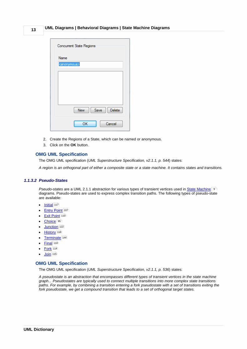
1. Right-click on the element, and select the Advanced | Define Concurrent Substates context menuoption. The State Regions dialog displays.
130 129 9
UML Diagrams | Behavioral Diagrams | State Machine Diagrams 13
UML Dictionary
2. Create the Regions of a State, which can be named or anonymous.
3. Click on the OK button.
OMG UML Specification
The OMG UML specification (UML Superstructure Specification, v2.1.1, p. 544) states:
A region is an orthogonal part of either a composite state or a state machine. It contains states and transitions.
1.1.3.2 Pseudo-States
Pseudo-states are a UML 2.1.1 abstraction for various types of transient vertices used in State Machinediagrams. Pseudo-states are used to express complex transition paths. The following types of pseudo-stateare available:
· Initial
· Entry Point
· Exit Point
· Choice
· Junction
· History
· Terminate
· Final
· Fork
· Join
OMG UML Specification
The OMG UML specification (UML Superstructure Specification, v2.1.1, p. 536) states:
A pseudostate is an abstraction that encompasses different types of transient vertices in the state machinegraph... Pseudostates are typically used to connect multiple transitions into more complex state transitionspaths. For example, by combining a transition entering a fork pseudostate with a set of transitions exiting thefork pseudostate, we get a compound transition that leads to a set of orthogonal target states.
9
117
107
110
95
122
116
144
110
114
115

UML Diagrams | Behavioral Diagrams | State Machine Table 14
© 1998-2010 Sparx Systems Pty Ltd
1.1.4 State Machine Table
A State Machine table is one of two variants of a State Machine (the other is the State Machine diagram) . Itdisplays the information of the State Machine in table form, and is a method of specifying the discrete behaviorof a finite state-transition system; that is, what state the State Machine moves to and the conditions underwhich the transition takes place.
You can display the state transition as one of two different relationships:
· State - Trigger: The rows indicate the current states and the columns indicate trigger events (or the otherway around if you prefer, in a Trigger - State format). The cell at the intersection of a row and columnidentifies the target state in the transition if the trigger occurs, and the condition (or guard) of the transition.
· State - Next State: The rows and columns both indicate states, and the cell at the intersection of a row andcolumn indicates the event that triggers a transition from the current (row) state to the next (column) state,the condition (or guard) of the event, and the effect of the transition.
9

UML Diagrams | Behavioral Diagrams | State Machine Table15
UML Dictionary
Select Format
You can display a State Machine as a diagram or table, and as a table in one of three relationship formats.
To select the display format, follow the steps below:
1. Right-click on the diagram background to display the context menu.
2. Select the Statechart Editor option.
3. Select the appropriate display option:
· Diagram
· Table (State-Next State)
· Table (State-Trigger)
· Table (Trigger-State)
To define the State Machine Table further, see:
· State Machine Table Options
· State Machine Table Operations
1.1.4.1 State Machine Table Options
You can choose the State Machine table layout and set other options from the State Machine Diagram:Options dialog, which you display by either:
· Double-clicking on the State Machine table background or
· Right-clicking on the background and selecting the State Table Options context menu option.
15
17
14

UML Diagrams | Behavioral Diagrams | State Machine Table 16
© 1998-2010 Sparx Systems Pty Ltd
Option Use to
Table Format Select the required table format:
· State - Trigger: rows represent States, each state name in a left edge cell;columns represent Triggers, each trigger name in a column header cell; theintersection of a row and column identifies the Transition (if there is one);the Transition cell displays information about the next State and thecondition (guard) of the Transition
· Trigger - State: as above, except that rows represent triggers and columnsrepresent states
· State - Next State: both rows and columns represent states; intersection ofrow and column defines the transition (if there is one) from the row state tothe column state.
Cell Size
Transition Cell Width Specify the width of the transition cells (that is, the column width).
Transition Cell Height Specify the height of the transition cells (that is, the row height).
Left Edge Cell Width Specify the width of the left edge (row title) cells.
Top Edge Cell Height Specify the height of the top edge (column title) cells.
Cell Color

UML Diagrams | Behavioral Diagrams | State Machine Table17
UML Dictionary
Option Use to
State/Trigger Cell Select the color of the row and column title cells.
State/TriggerEnumeration
Select the color of the enumeration (row/column numbering) cells.
Note:
You must select at least one of the Enable State Enumeration and EnableEvent Enumeration checkboxes to set this color.
Transition Cell Select the color of the transition cells (in the main body of the table).
Highlight Options
Highlight Zones Relatedto Selected Transition
Highlight the cells for all elements involved in a selected transition - the initialstate, the target state, and the trigger.
Highlight Color Select the color of the highlight.
Use Different Color forTarget State
Highlight the cell for the target element in a transition in a different color to thecell for the source element.
Target Zone Color Select the color of the highlight.
Display Options
Always Display anEmpty State Zone
Add an empty row (and, on a State - Next State table, an empty column) to theend of the table.
The title cell contains an ellipsis (...). You can click twice (not double-click) onthe ellipsis to edit it and identify a new state. In this case, another empty statezone is automatically added.
Enable StateEnumeration
Add a cell to each state title cell, to number the state. Numbering starts at 0.
Prefix If required, type a prefix for the state number or delete the default S to have noprefix.
Enable EventEnumeration
Add a cell to each event or trigger title cell, to number the event. Numberingstarts at 0.
Prefix If required, type a prefix for the event number or delete the default E to have noprefix.
Sample State Table Display a preview of the table format as you define it.
Advanced Define diagram options. The State Machine Diagram Properties dialog displays.(See UML Modeling with Enterprise Architect – UML Modeling Tool forinformation on the Diagram Properties dialog.)
Restore Defaults Reapply the State Table diagram default values.
Apply Apply changed options to the State Table diagram.
1.1.4.2 State Machine Table Operations
Overview
As a State Machine table is a variant of a UML State Machine diagram , most of the operations formanipulating the data are the same as for State Machine diagrams. These include operations to:
· Create new items by drag-and-dropping a specified object from the Enterprise Architect UML Toolbox tothe current diagram
14 9

UML Diagrams | Behavioral Diagrams | State Machine Table 18
© 1998-2010 Sparx Systems Pty Ltd
· Delete an item
· Apply to the diagram elements in the Project Browser
· Display or change the properties of the State, Trigger or Transition
· Apply to the diagram, such as Lock Diagram, Zoom, and in place editing of the element.
The operations specific to State Machine tables are described in the following topics:
· Change Position of State Machine Table
· Change Size of State Machine Table
· Insert New State (and Substate)
· Insert Trigger
· Insert/Change Transition
· Reposition State/Trigger Cells
· Add Legend
· Find Cell in State Machine Diagram
· State Machine Table Conventions
· Export State Table To CSV File
1.1.4.2.1 Change State Machine Table Position
If necessary, you can move the State Machine table around in the Diagram View. To change the position ofthe State Machine table, follow the steps below:
1. Press [Ctrl]+[A] or double click on the top left cell to select the whole State Machine table.
2. Drag and drop the State Machine table to the required position. Alternatively, use [Shift]+["], [!], [#]or [$] to move the State Machine table.
1.1.4.2.2 Change State Machine Table Size
There are three ways to change the size of the State Machine table:
· Change the cell size on the State Machine Diagram: Options dialog.
· Press [Ctrl]+[A] or double click on the top left cell to select the whole State Machine table, then press[Ctrl]+["], [!], [#] or [$] to change the size.
· Select the State Machine table, then drag the shape handles to change the size.
1.1.4.2.3 Insert New State
You can insert a new State in the State Machine table, using one of following methods:
· In the top left cell in the State Machine table, move the cursor to the word State to display a + at the end ofthe word; click on the + to create a new State
· Right-click in the top left cell in the State Machine table to display the context menu, and select the AddState menu option
· Right-click on an existing State cell in the State Machine table to display the context menu, and select the
· Insert New State Before option to insert a new State before the current State, or
· Insert New State After option to insert a new State after the current State
· Click on an existing State cell in the State Machine table, and press [Insert] to create and insert a newState above the selected State
· In the Enterprise Architect UML Toolbox, on the State Elements page, click on an element and then clickon:
· the diagram background to add a new State to the end of the table, or
· an existing State cell to add the new State just above it.
Note:
From the State Elements page of the Enterprise Architect UML Toolbox you can insert State, Initial, Final,Entry, Exit and Terminate elements.
18
18
18
19
19
20
20
20
21
21
15

UML Diagrams | Behavioral Diagrams | State Machine Table19
UML Dictionary
Add a Substate
To add a Substate to a selected State, follow the steps below:
1. Right-click on the required State cell in the State Machine table. The context menu displays.
2. Select the Add Substate menu option. Enterprise Architect adds the Substate to the State.
Note:
If the selected State does not allow a Substate, then the Add Substate menu option is grayed out.
You can also drag one existing State over another. If the second State allows Substates, the dragged Statethen becomes its Substate.
Similarly, you can change the parent State of a Substate by dragging the Substate from the original parentState to a different State.
Remove Parent Relation of a Substate
To remove the parent relation of a Substate and make it a separate State, follow the steps below:
1. Right-click on the Substate in the State Machine table. The context menu displays.
2. Select the Remove Parent Relation menu option. The Substate cell becomes a State cell.
You can also drag and drop the Substate onto the top left cell of the State Machine table. The draggedSubstate again becomes a State cell.
1.1.4.2.4 Insert Trigger
If the State Machine table format is either State-Trigger or Trigger-State, you can use one of the followingmethods to insert a new Trigger:
· In the top left cell in the State Machine table, move the cursor to the word Event to display a + at the end ofthe word; click on the + to create a new Trigger
· In the top left cell in the State Machine table, right-click to display the context menu and select the AddTrigger menu option to create a new Trigger
· Select an existing Trigger in the State Machine table, then press [Insert] to insert a new Trigger before theexisting Trigger
· Click on an existing Trigger in the State Machine table, right-click to display the context menu and selecteither the:
· Insert New Trigger Before option to insert a new Trigger before the current Trigger, or
· Insert New Trigger After option to insert a new Trigger after the current Trigger.
1.1.4.2.5 Insert/Change Transition
You can insert a new Transition using one of the following methods:
· Right-click on the cell in which to create a Transition, to display the context menu
· If the State Machine table format is State-Trigger or Trigger-State, the context menu lists the Statesyou can choose as the target of the Transition; click on the required State name to create theTransition
· If the State Machine table format is State-Next State, click on the Insert Transition menu option tocreate the Transition.
· In the State Relationships page of the Enterprise Architect UML Toolbox, select the Transition element,then click on the cell in the State Machine table in which to create the Transition. Double-click on theTransition to define it in the Transition Properties dialog.
Change the Transition
As for the State Chart diagram, to change the properties of a Transition double-click the Transition cell andedit the details on the Transition Properties dialog.
9

UML Diagrams | Behavioral Diagrams | State Machine Table 20
© 1998-2010 Sparx Systems Pty Ltd
Change Transition States
You can change the source and target of the Transition by right-clicking the Transition and selecting the Advanced | Set Source and Target context menu option.
Alternatively, you can change the Transition source, target or Trigger by clicking on the Transition anddragging it to a different cell.
If the State Machine table format is either State-Trigger or Trigger-State, you can change the target state of atransition by:
1. Highlighting the target state name in the Transition cell and clicking on it to display a list of the states inthe table.
2. Clicking on the preferred target state name.
Highlight States and Trigger Related to Transition
You can select options to highlight the source State, target State and Trigger cells associated with aTransition, using the Highlight Options panel on the State Machine Diagram Options dialog. When youclick on the Transition cell its associated State and Trigger cells are highlighted.
Alternatively, click on the Transition cell and press and hold [L].
1.1.4.2.6 Reposition State or Trigger Cells
You can change the position of a selected State or Trigger cell in one of the following ways:
· Right-click on the State or Trigger title cell and select the appropriate Order | Move xxx context menuoption
· Click on the cell and press [Shift]+["], [!], [#] or [$].
1.1.4.2.7 Add Legend
You can add a simple legend to any State Machine Table cell that has no transition. The two legend symbolsare:
· I - Ignore
· N - Never Happen
To assign a legend symbol to a State Machine Table cell, follow the steps below:
1. Right-click on the cell to which to assign the legend. The context menu displays.
2. Select the appropriate menu option:
· Legend | Ignore
· Legend | Never Happen.
The required symbol displays in the center of the cell.
To remove a legend symbol from a cell, right-click on the cell and select the Legend | Remove Legendcontext menu option.
1.1.4.2.8 Find Cell in State Machine Diagram
On the State Machine table you can select a State or Trigger element and locate it in a State Machinediagram, by selecting the Find | Locate in State Chart context menu option. Enterprise Architect switches tothe State Machine diagram and highlights the selected element. You can locate a Transition relationship in asimilar way, by selecting the Locate in State Chart context menu option.
Note:
A Trigger on a State Machine table might or might not exist on the corresponding State Machine diagram. Ifthe Trigger does not exist on the State Machine diagram, the Locate in State Chart option is disabled.
Conversely, on the State Machine diagram, you can select a State or Trigger element and locate it on thecorresponding State Machine table, by selecting the Find | Locate in State Table context menu option.
15

UML Diagrams | Behavioral Diagrams | State Machine Table21
UML Dictionary
Enterprise Architect switches to the State Machine table and highlights the selected element. You can locate aTransition relationship in a similar way, by selecting the Locate in State Table context menu option.
1.1.4.2.9 State Machine Table Conventions
Trigger· Deleting a Trigger removes it completely from the model, therefore you cannot UNDO a Trigger deletion
· There is a <None> column at the end of the Event heading row. This is for Transitions that have no Triggerinformation.
State
From the Enterprise Architect UML Toolbox you can insert the following State element types only (although theState Machine table might pick up and display other types, such as Submachine State):
· State
· Initial
· Final
· Entry
· Exit
· Terminate.
Transition
The Transition cell displays its properties in one of two ways, depending on the State Machine table format. Ifthe State Machine table format is State - Trigger or Trigger - State, the Transition cell displays the Guard andTarget as shown below:
If the State Machine table format is State - Next State, then the Transition cell displays the Trigger, Guard andEffect as shown below:
The State Machine table enables you to edit the Guard and Effect in place. If the Guard or Effect is empty foryour selected Transition cell, the cell displays an ellipsis [ ... ] instead. Click twice (not double-click) on theellipsis to type in the Guard and Effect names.
1.1.4.2.10 Export State Table To CSV File
To export a State Machine Table to a CSV file, follow the steps below:
1. Open the required State Machine Table.
2. Right-click on the diagram background and select the Export Statechart to CSV file context menuoption.
3. The Save As browser dialog displays. Select the appropriate directory location and type in the .CSVfilename.
4. Click on the Save button.

UML Diagrams | Behavioral Diagrams | Timing Diagram 22
© 1998-2010 Sparx Systems Pty Ltd
1.1.5 Timing Diagram
One of four types of Interaction diagram. (The other three are Sequence Diagrams , Interaction OverviewDiagrams and Communication Diagrams .)
A Timing diagram defines the behavior of different objects within a time-scale. It provides a visualrepresentation of objects changing state and interacting over time.
You can use Timing diagrams to define hardware-driven or embedded software components; for example,those used in a fuel injection system or a microwave controller. You can also use Timing diagrams to specifytime-driven business processes.
To create and edit a Timing diagram, see the following topics:
· Create a Timing Diagram
· Set a Time Range
· State Lifeline
· Value Lifeline
· Edit a Timing Diagram
· Time Intervals
· Message (Timing Diagram)
Example Diagram
An example of a Timing diagram is shown below:
(See OMG UML Superstructure Specification, v2.1.1, p. 454, figures 14.30 and 14.31).
Toolbox Elements and Message
Select Timing diagram elements and connectors from the Timing pages of the Enterprise Architect UMLToolbox; see Using Enterprise Architect – UML Modeling Tool.
Tip:
Click on the following elements and connectors for more information.
39
52 49
23
23
135
149
24
32
226

UML Diagrams | Behavioral Diagrams | Timing Diagram23
UML Dictionary
Timing Diagram Elements Timing Diagram Message
OMG UML Specification
The OMG UML specification (UML Superstructure Specification, v2.1.1, p. 517) states:
Timing Diagrams are used to show interactions when a primary purpose of the diagram is to reason abouttime. Timing diagrams focus on conditions changing within and among Lifelines along a linear time axis.
Timing diagrams describe behavior of both individual classifiers and interactions of classifiers, focusingattention on time of occurrence of events causing changes in the modeled conditions of the Lifelines.
The OMG UML specification (UML Superstructure Specification, v2.1.1, p. 519) also states:
The primary purpose of the timing diagram is to show the change in state or condition of a lifeline(representing a Classifier Instance or Classifier Role) over linear time. The most common usage is to show thechange in state of an object over time in response to accepted events or stimuli. The received events areannotated as shown when it is desirable to show the event causing the change in condition or state.
1.1.5.1 Create a Timing Diagram
To create a Timing diagram, follow the steps below:
1. Right-click on a package in the Project Browser. The context menu displays.
2. Select the Add | Add Diagram menu option. The New Diagram dialog displays.
3. In the Select From panel, select UML Behavioral.
4. In the Diagram Types panel, select Timing.
5. Click on the OK button. The Diagram view displays, on which you create the Timing elements for thediagram. See Set a Time Range and Edit a Timing Diagram .
1.1.5.2 Set a Time Range
Before adding Lifeline elements to your Timing diagram, set a time range. To do this, follow the steps below:
1. Right-click on the diagram. The context menu displays.
2. Select the Set Timeline Range option. The Set Timeline Range dialog displays.
3. In the Start Time and End Time fields, type the numeric values for the start and end points of the
23 24

UML Diagrams | Behavioral Diagrams | Timing Diagram 24
© 1998-2010 Sparx Systems Pty Ltd
timeline; for example, set the range 0 to 100.
Note:
The start time must be less than the end time.
4. In the Time Units field, type the unit in which the time is measured; for example, seconds or minutes.
5. If it is not necessary to show the time range on the diagram, select the Suppress In Diagramcheckbox.
6. Click on the OK button. If you have not suppressed it, the time range displays underneath the Lifelineelements that you create on the diagram.
1.1.5.3 Edit a Timing Diagram
On a Timing Diagram, you can add State Lifeline elements and Value Lifeline elements. You can maintain thestates and transitions on these Lifeline elements either on the diagram itself or via the Configure Timelinedialog. See the following topics:
· Add and Edit a State Lifeline Element
· Edit States in a State Lifeline Element
· Edit Transitions in a State Lifeline Element
· Add and Edit a Value Lifeline Element
· Add States in a Value Lifeline Element
· Edit Transitions in a Value Lifeline Element
· Configure Timeline dialog - States Tab
· Configure Timeline dialog - Transitions Tab
1.1.5.3.1 Add and Edit State Lifeline
From the Timing elements page of the Enterprise Architect UML Toolbox drag a State Lifeline elementonto your diagram. The element displays on the diagram.
To define the name of the State Lifeline, follow the steps below:
1. Right-click on the element. The context menu displays.
2. Select the Other Properties option. The Timeline <name> dialog displays, showing the General tab.
3. Overtype the Name field.
4. Click on the Apply button and the OK button.
Sizing and Scale
In the top left corner of a selected Lifeline element are the left and right quick sizing buttons ( ). Thesebuttons increase or decrease the width of the Lifeline element, which in turn controls the scale width of eachtime unit. By increasing the width of the element you increase the resolution when adding transitions, whichmakes them easier to edit.
Note:
In order to edit the State Lifeline element, you must click on it to select it.
Set Timeline Start Position
You might require more space at the start of your timelines; for example, to use long state names. To insertthis space in all the timelines on a diagram, follow the steps below:
1. Right-click on the diagram background to display the context menu.
2. Select the Set Timeline Start Position menu option. The Set Timeline Start Position dialog displays.
3. The Value 80 to 300 field defaults to 80 as the minimum distance in pixels between the start of thetimeline element and the start of the timeline itself. Type a new value up to 300 pixels and click on the OK button to increase the space at the start of the timeline, as shown in the following diagrams.
24
25
26
27
28
28
29
31
135

UML Diagrams | Behavioral Diagrams | Timing Diagram25
UML Dictionary
80 Pixels 150Pixels
You now edit the states and transitions in the State Lifeline.
1.1.5.3.2 Edit States In State Lifeline
Add States
1. Click on the State Lifeline element. The New State button ( ) and Edit States button ( ) display atthe bottom left of the element.
2. Click on the New State button. The New State dialog displays.
3. In the State field, type the name of the state.
4. Click on the OK button.
Note:
You must add at least two states; for example, On and Off.
5. As you add states, increase the height of the element by dragging a handle-box ( ) on the edgeof the element.
Note:
You can also add states using the States tab of the Configure Timeline dialog. Add either:
· Discrete states to the Timeline as described in Add a New State , or
· A continuous range of numeric states as described in Numeric Range Generator .
Edit States
1. Click on the State Lifeline element and click on the required state. The Edit State dialog displays.
2. In the State field, change the name as required.
3. Click on the OK button.
4. If necessary, change the order of the states by either:
· Clicking on the up or down arrows ( and ) beside each state name, or
25 26
30
30

UML Diagrams | Behavioral Diagrams | Timing Diagram 26
© 1998-2010 Sparx Systems Pty Ltd
· Right-clicking on the state name and selecting the Move Up or Move Down context menu options.
Note:
You can also edit the states using the States tab of the Configure Timeline dialog.
Delete States
1. Right-click on the state name. The context menu displays.
2. Select the Delete option.
Alternatively:
1. Click on the State Lifeline element.
2. Hold down [Ctrl] and move the cursor over the state name. The cursor changes form (7 ).
3. Click the mouse button. The state name is deleted.
1.1.5.3.3 Edit Transitions In State Lifeline
Add and Move Transitions
After you have added states, you can add transitions via the diagram. As you move the cursor over thetimeline, the cursor changes to one of three shapes:
· The move cursor ( ) displays when it is directly over the timeline. Hold down the mouse button and dragthe line to move the timeline to a state above or below the current position. You can move the transitionmore than one state up or down, if necessary.
· The new transition up cursor ( ) displays when it is just below the timeline, and there is another state
above the line. Press and hold [Alt]; the cursor changes ( ). Click to create a new transition to the stateabove the line. To push the transition up more than one state, then move the cursor onto the line and dragit up. The transition is for one interval unit; to make it longer, see Change the Transition Time below.
If you do not hold [Alt], the cursor does not change and the whole timeline from the transition onwardsmoves up.
· The new transition down cursor ( ) displays when it is just above the transition line, and there is another
state below the line. Press and hold [Alt]; the cursor changes ( ). Click to create a new transition to thestate below the line. To push the transition down more than one state, then move the cursor onto the lineand drag it down. The transition is for one interval unit; to make it longer, see Change the Transition Timebelow.
If you do not hold [Alt], the cursor does not change and the whole timeline from the transition onwardsmoves down.
As you move the cursor over the vertical line of a transition, the time at which the transition occurs displaysnext to the line.
Edit Transitions
Follow the steps below:
1. Click directly on the appropriate transition line, after the transition begins. Alternatively, right-click on thetransition line to display the context menu, and select the Edit menu option.
The Edit Transition dialog displays. The fields in this dialog are all optional.
29

UML Diagrams | Behavioral Diagrams | Timing Diagram27
UML Dictionary
2. In the At Time field, type the point on the timescale at which the transition occurs.
3. In the Transition To field, type the name of the state to which the transition occurs.
4. In the Event field, type the name of the event that the transition represents; this displays on theTimeline element just above the transition line.
5. In the Duration Constraint field, type any constraint on the duration of the transition; this displays onthe Timeline element, along the top of the element over the transition.
6. In the Time Constraint field, type any constraint on the start of the transition. This displays on theTimeline element at the start of the transition.
7. Click on the OK button.
Notes:
· Once Event, Duration Constraint or Time Constraint are displayed on the diagram, you can edit themdirectly by clicking on them to display their specific dialog. You can also delete them by pressing andholding [Ctrl] as you click on them; the cursor changes form when you press [Ctrl].
· You can also edit transitions using the Transitions tab of the Configure Timeline dialog.
Change the Transition Time
Move the cursor over one or other of the vertical transition lines and drag the line left or right to change thetime of the transition. While on the line, the cursor shape changes to the horizontal movement cursor ( ).
Merge Transitions
If necessary, you can 'push' a transition to merge it with the next or previous transition point on any Lifelineelement on the diagram.
Position the cursor off the appropriate side of the transition line; the cursor changes form ( or ). Clickthe mouse button. The system locates the nearest transition in the required direction, on any element on thediagram, and merges the current transition with that transition.
Delete Transitions
Transitions are automatically deleted when you move the transition to the same state as the previoustransition state, and release the cursor.
Alternatively, right-click on the transition line to display the context menu, and select the Delete menu option.
1.1.5.3.4 Add and Edit Value Lifeline
From the Enterprise Architect UML Toolbox drag a Value Lifeline element onto your diagram. The elementdisplays on the diagram.
To edit the Value Lifeline name, follow the steps below:
1. Right-click on the element. The context menu displays.
2. Select the Other Properties option. The Timeline <name> dialog displays, showing the General tab.
31
149

UML Diagrams | Behavioral Diagrams | Timing Diagram 28
© 1998-2010 Sparx Systems Pty Ltd
3. Overtype the Name field.
4. Click on the Apply button and the OK button.
Sizing and Scale
In the top left corner of a selected Lifeline element are the left and right quick sizing buttons ( ). Thesebuttons increase or decrease the width of the Lifeline element, which in turn controls the scale width of eachtime unit. By increasing the width of the element you increase the resolution when adding transitions, whichmakes them easier to edit.
Note:
In order to edit the Value Lifeline element, you must click on it to select it.
You now add states and edit transitions on the Value Lifeline.
1.1.5.3.5 Add States In Value Lifeline
Add States
This is similar to adding states to a State Lifeline element.
Notes:
· For a Value Lifeline, only the first state displays on the diagram. The other states are added to a list toaccess when creating transitions; they only display on the Lifeline element as you create transitions tothose states.
· You can only edit or delete states in a Value Lifeline element using the States tab of the ConfigureTimeline dialog.
1.1.5.3.6 Edit Transitions In Value Lifeline
Add Transitions
After you have added states to the Value Lifeline element, you can add transitions via the diagram. To do this,follow the steps below:
1. Move the cursor above the transition line. The cursor changes form ( ).
2. Click the mouse button. The New Transition Event dialog displays.
3. In the Transition To field, click on the drop-down arrow and select a state from the list of availablestates; this displays on the Lifeline element within the transition box. The remaining fields on the dialogare optional.
4. In the Event field, type the name of the event that the transition represents; this displays on the Lifelineelement just below and at the start of the transition line.
28 28
25
29

UML Diagrams | Behavioral Diagrams | Timing Diagram29
UML Dictionary
5. In the Duration Constraint field, type any constraint on the duration of the transition; this displays onthe Lifeline element, along the top of the element over the transition.
6. In the Time Constraint field, type any constraint on the start of the transition. This displays on theLifeline element at the start of the transition, just after the Event name.
7. Click on the OK button to create the new transition.
Edit Transitions
To edit a transition, follow the steps below:
1. Click on the state name in the transition. Alternatively, right-click on the state name to display thecontext menu, and select the Edit menu option.
The Edit Transition dialog displays; this is the same as the New Transition Event dialog, except that theAt Time field is enabled.
2. If necessary, overtype the At Time field to define a different start point.
Note:
You cannot change the At Time field for the first state in the timeline; this is always 0.
3. Edit the remaining fields as necessary.
4. Click on the OK button to save the changes.
Change the Transition Time
To change the start or end time of a transition, click on the start or end point of the transition and drag it to the
new position. While on the line, the cursor shape changes to the horizontal movement cursor ( ).
Delete Transitions
To delete a transition, press and hold [Ctrl] and click on the transition state name. While you hold [Ctrl] on thetransition state name, the cursor changes form (7 ).
Alternatively, right-click on the state name to display the context menu, and select the Delete menu option.
1.1.5.3.7 Configure Timeline - States
You can also manage states using the States tab of the Configure Timeline dialog. To display this, either:
· Double-click on the Lifeline element
· Right click on the Lifeline element and, from the context menu, select the Properties option, or
· On a Value Lifeline, click on the Edit States button ( ).

UML Diagrams | Behavioral Diagrams | Timing Diagram 30
© 1998-2010 Sparx Systems Pty Ltd
The Configure Timeline dialog defaults to the States tab.
All states currently defined for the Lifeline element are listed in the States panel.
Add a New State:
1. In the State Name field, type the name of the first new state in the Lifeline element; for example,WaitState.
2. Click on the Save button. The state is added to the States panel and (for a State Lifeline Element) to thediagram.
3. Click on the New button.
4. In the State Name field, type the name of the next state in the Lifeline element.
5. Repeat steps 2 to 5 until you have added all required states (you must add at least three to the Lifelineelement).
6. When you have added all the required states, click on the OK button to close the Configure Timelinedialog.
Edit an Existing State:
1. Click on the state in the States: list.
2. In the State Name field, change the name of the state.
3. Click on the Save button.
Delete an Existing State:
1. Click on the state in the States: list.
2. Click on the Delete button.
Change the Order of States:
1. Click on the state in the States: list.
2. Click on the or buttons to move the state up or down the sequence.
Numeric Range Generator
You can also use the Configure Timeline dialog to create a range of states having numeric values to beapplied to the Timeline.

UML Diagrams | Behavioral Diagrams | Timing Diagram31
UML Dictionary
Important:
This operation deletes all existing states and transitions for the Timeline element.
1. Display the Configure Timeline dialog.
2. Click on the Create Continuous Numeric States button. The Numeric Range Generator dialogdisplays.
3. In the High Value and Low Value fields, type the upper and lower values of the range.
4. In the Step Value field, type the increase interval.
Note:
Nonsense values do not parse; Low Value must be less than High Value, and Step Value must be apositive value smaller than the total range.
5. In the Units field, type the name of the measurement unit; for example, minutes.
6. Click on the OK button. Enterprise Architect displays a warning that existing states and transitions willbe deleted.
7. Click on the Yes button. The Configure Timeline dialog redisplays, with the defined range of stateslisted in the States panel.
8. Click on the OK button. For a:
· Value Lifeline, the first state is shown on the Timeline for the full time range of the Timeline.
· State Lifeline, the range of states is displayed as the y-axis of the Timeline.
1.1.5.3.8 Configure Timeline - Transitions
You can also manage transitions using the Transitions tab of the Configure Timeline dialog. To display this,either:
· Double-click on the Lifeline element
· Right click on the Lifeline element and, from the context menu, select the Properties option, or
· On a Value Lifeline, click on the Edit States button ( ).
The Configure Timeline dialog defaults to the States tab. Click on the Transitions tab.

UML Diagrams | Behavioral Diagrams | Timing Diagram 32
© 1998-2010 Sparx Systems Pty Ltd
All transitions defined for the Timeline element are listed in the Transition Points panel.
Add a New Transition
1. Click on the New button.
2. In the New Transition panel, type the details of the transition.
3. Click on the Save button.
Edit a Transition
1. Click on a transition in the list.
2. In the Edit Transition panel, edit the fields for the transition as required.
3. Click on the Save button.
Delete a Transition
1. Click on a transition in the list.
2. Click on the Delete button. The transition is removed from the dialog and the Lifeline.
3. Click on the OK button.
1.1.5.4 Time Intervals
You create and manage Time Intervals using the Interval Bar (the pale line along the top of each selectedLifeline element). Time Intervals enable you to perform various operations on transitions, such as copy andpaste. They also enable you to compress sections of the timeline so that they are not visible.
Each Time Interval displays across all Timeline elements down to the last element on the diagram.
Create Time Intervals
To create a Time Interval, follow one of the three sets of steps below:

UML Diagrams | Behavioral Diagrams | Timing Diagram33
UML Dictionary
Interval Bar - Context Menu
1. Right-click on the Interval Bar at approximately the point at which to start or finish the Time Interval.
The context menu displays.
2. Select the Create Time Interval option. The Time Interval displays down all the timeline elements, as anarrow pale band with a blue compression box at the top.
3. Move the cursor to the edge of the Time Interval in the Interval Bar so that the cursor changes to the
drag form ( ) and drag the edge to the correct start or end point.
Interval Bar - [Shift] key
1. Move the cursor over the Interval Bar and press [Shift]. The cursor changes shape ( ).
2. Click to create the Time Interval.
3. Move the cursor to the edge of the Time Interval in the Interval Bar so that the cursor changes to the
drag form ( ) and drag the edge to the correct start or end point.

UML Diagrams | Behavioral Diagrams | Timing Diagram 34
© 1998-2010 Sparx Systems Pty Ltd
Timeline - Context menu
1. Right-click on the timeline just after a transition. The context menu displays.
2. Click on the Select menu option. Enterprise Architect creates a Time Interval covering the period fromthe selected transition up to the next transition.
Notes:
· If there are other Time Intervals in this period, Enterprise Architect replaces them with the single TimeInterval for the transition state. You should consider this when creating the Time Interval, as it extendsacross the other Timeline Elements in the diagram.
· A value of this method is that it creates a Time Interval for a period in which no transitions occur, whichcould be lengthy. You can then compress this Time Interval (see below) to hide the period of inactivity. Seealso Compress Timeline .
Compress Time Intervals
You can compress Time Intervals to conserve space on long timelines.
Uncompressed Time Intervals
Compressed Time Intervals
Notice:
37

UML Diagrams | Behavioral Diagrams | Timing Diagram35
UML Dictionary
Item Description
The compression toggle boxes:
· is expanded, click on this to compress the selected time interval
· is compressed, click on this to expand the selected time interval again.
The compressed sections of the timelines themselves, in all elements.
If there is space between the paired symbols, there are transitions within thecompressed section.
If the timeline continues through the paired symbols there are no transitions in thecompressed section.
25 ... 55 The compressed sections in the time range underneath the elements.
You can also compress and expand Time Intervals using context menu options; see Time Interval Operationson Transitions .
Select Time Intervals· To select a Time Interval across all elements on the diagram, click on the Interval Bar within the Time
Interval.
· To select a number of individual Time Intervals, press and hold [Ctrl] while clicking on the Interval Barwithin each Time Interval.
· To select all Time Intervals in a range, click on the Interval Bar within the first Time Interval in the range,then press and hold [Shift] and click on the Interval Bar within the last Time Interval in the range. All TimeIntervals between the two are selected.
After you have selected one or more Time Intervals, you can modify the selection in the following ways:
· To exclude Lifeline elements from the selection, press and hold [Ctrl] and click on any part of the selectionwithin that element. In the diagram below, the Value Lifeline is excluded from selection.
Repeat the step to toggle the selection and re-include the element. See also Toggle Interval Selection .
· To select only one Lifeline element and exclude all others, press and hold [Shift] and click on any part ofthe selection within that element.
Note:
Selection is useful for cutting, copying and pasting transitions.
Move and Resize Time Intervals
To move a Time Interval, move the cursor over the Interval bar within the Time Interval, hold down the mousebutton and drag the interval left or right.
To resize a Time Interval, move the cursor over the Interval Bar at the start or end edge of the Time Interval,
36
36

UML Diagrams | Behavioral Diagrams | Timing Diagram 36
© 1998-2010 Sparx Systems Pty Ltd
hold down the mouse button and move the edge left or right.
Note:
Time Intervals can meet, but cannot overlap.
Delete Time Intervals
Select each Time Interval to be deleted and press [Delete].
Note:
Deleting the Time Interval does not delete transitions within that interval.
1.1.5.4.1 Time Interval Operations
You can operate on selected Time Intervals , or all Time Intervals in the diagram.
Selected Intervals
Note:
The Copy, Cut and Delete operations act on all selected Time Intervals over the whole diagram, not just thecurrent one.
To select and update specific Time Intervals, right-click on the Interval Bar within an interval. The followingcontext menu displays.
Option Use to
Select Interval
Deselect Interval
Select the Time Interval or, if the interval is already selected, deselect it. You canselect several Time Intervals in this way, accessing the menu separately on eachinterval.
Toggle IntervalSelection
Switch the selection or deselection of the Time Interval within the selectedTimeline element.
You select or deselect a Time Interval across all Timeline Elements, but theToggle option acts only on the element in which you access the menu. See also Select Time Intervals .
35
32
35

UML Diagrams | Behavioral Diagrams | Timing Diagram37
UML Dictionary
Option Use to
Compress Interval Compress the Time Interval, and hide all transitions within that Time Interval.This is also useful for hiding long sections of inactivity on the time line. Also see Compress Timeline , below.
Remove Interval Delete the Time Interval.
Copy Copy the transitions for all selected Time Intervals.
Cut Copy and delete the selected transitions from the diagram.
Cut and Remove Time Copy and delete the transitions that lie in the selected Time Intervals from thediagram.
This option also removes time from the timeline, the amount being the durationof the Time Interval. All transitions and Time Intervals to the right of the selectedtime interval are moved left.
Delete Delete the selected transitions from the diagram.
Delete and RemoveTime
Delete the transitions that lie in the selected Time Intervals from the diagram.
This option also removes time from the timeline, the amount being the durationof the Time Interval. All transitions and Time Intervals to the right of the currentTime Interval are moved left.
Insert Time Add time to the timeline and move all transitions and time intervals to the right.Also expand the duration of the current Time Interval.
Compress Timeline
The Compression toggle boxes and Compress Interval menu option operate on the Time Interval andcompress the timeline and all transitions within the Interval. You have an alternative option that operates onthe timeline and compresses a single transition state.
1. Right-click on the timeline (rather than the Interval Bar) just after a transition. The context menudisplays.
2. Click on the Compress menu option. Enterprise Architect creates a new Time Interval covering theperiod from the selected transition up to the next transition, and then compresses that Time Interval.
Notes:
· If there are other Time Intervals in this period, Enterprise Architect replaces them with the single TimeInterval for the transition state. You should consider this when creating and compressing the Time Interval,as it extends across the other Timeline elements in the diagram.
· A value of this method is that it creates a Time Interval for a period in which no transitions occur, whichcould be lengthy, and then compresses this Time Interval to hide the period of inactivity.
All Time Intervals in the Diagram
To create a new Time Interval or work across all Time Intervals in the diagram, right-click on the Interval Bar between Time Intervals. The following context menu displays.
37

UML Diagrams | Behavioral Diagrams | Timing Diagram 38
© 1998-2010 Sparx Systems Pty Ltd
Note:
The Paste menu options become active after transitions have been copied.
Menu Option Use to
Create Time Interval Create a single Time Interval .
Expand all Time Intervals Expand all Time Intervals over the whole diagram.
Compress all TimeIntervals
Compress all Time Intervals over the whole diagram.
Paste Combine Paste copied transitions over any existing transitions within the copied timeframe.
Note:
The diagram does not allow two consecutive transitions to the same state, andremoves the second transition automatically.
Paste Remove Delete all the transitions and then pastes the copied transition within the copiedtime frame.
Paste Insert Insert time, moving all transitions and Time Intervals to the right to make roomto paste in the copied transitions.
Insert Time Add time to the timeline and move all transitions and Time Intervals to the right.This option does not change the duration of any Time Interval.
Copy and Paste Transitions From One Timeline Element to Another
A special mode enables you to copy transitions from one Timeline element to another. Any states that don'texist in the Timeline element you are pasting to are created.
1. Press and hold [Shift] and select the Timeline element within a Time Interval to copy or cut.
2. Right-click on the Interval Bar (it doesn't matter which element you select). The context menu displays.
3. Copy or cut the transitions. You can also cut and remove time.
4. Select the timeline to paste transitions to and right-click on the Interval Bar. The context menu displays.
5. Select one of the paste operations. Note that states are created if they don't already exist in thetimeline.
Note:
Any new states created might be in the wrong order. You can change the order via the diagram quick buttons.
32
37
24

UML Diagrams | Behavioral Diagrams | Timing Diagram39
UML Dictionary
Shift Transitions Left or Right
You can move transitions within a selected Time Interval or multiple selected Time Intervals.
1. Select all the Time Intervals containing the transitions to be shifted; see Select Time Intervals .
2. Press and hold [Shift] and click on the Interval Bar (it doesn't matter which Timeline element you select)and move the transition left or right.
Note:
You cannot drag transitions over other transitions; the move stops when the moved transition collides with astationary transition.
Tip:
If having collision problems, use [Shift]+select to shift transitions for a single Timeline element.
1.1.6 Sequence Diagram
A Sequence diagram is one of four types of Interaction diagram. (The other three are Timing Diagram ,Interaction Overview Diagram and Communication Diagram .)
A Sequence diagram is a structured representation of behavior as a series of sequential steps over time. It isused to depict work flow, message passing and how elements in general cooperate over time to achieve aresult.
· Each sequence element is arranged in a horizontal sequence, with messages passing back andforward between elements.
· Messages on a Sequence diagram can be of several types; the Messages can also be configured to reflectthe operations and properties of the source and target elements (see the Notes in the Message topic).
· An Actor element can be used to represent the user initiating the flow of events.
· Stereotyped elements, such as Boundary , Control and Entity , can be used to illustrate screens,controllers and database items, respectively.
· Each element has a dashed stem called a lifeline, where that element exists and potentially takes part inthe interactions.
To configure a Sequence diagram, see the following topics:
· Denote the Lifecycle of an Element
· Layout of Sequence Diagrams
· Sequence Element Activation
· Lifeline Activation Levels
· Message Label Visibility
· Change the Top Margin
· Change the Timing Details .
Also take note of the important information in the Sequence Diagrams and Version Control topic.
Robustness diagrams, used extensively in ICONIX, can be created as Sequence diagrams.
To toggle the numbering of messages on a Sequence diagram, select or deselect the Show SequenceNumbering checkbox on the Options dialog; see Using Enterprise Architect – UML Modeling Tool.
Example Diagram
The following example Sequence diagram demonstrates several different elements:
35
22
52 49
43
212
179 181 182
41
42
45
46
48
48
218
44

UML Diagrams | Behavioral Diagrams | Sequence Diagram 40
© 1998-2010 Sparx Systems Pty Ltd
Toolbox Elements and Connectors
Select Sequence diagram elements and connectors from the Interaction pages of the Enterprise ArchitectUML Toolbox; see Using Enterprise Architect – UML Modeling Tool.
Enterprise Architect also supports a number of stereotyped elements to represent various entities inbusiness modeling.
Tip:
Click on the following elements and connectors for more information.
Sequence Diagram Elements Sequence Diagram Connectors
75

UML Diagrams | Behavioral Diagrams | Sequence Diagram41
UML Dictionary
Sequence Diagram Elements Sequence Diagram Connectors
OMG UML Specification
The OMG UML specification (UML Superstructure Specification, v2.1.1, p. 503) states:
A sequence diagram describes an Interaction by focusing on the sequence of Messages that are exchanged,along with their corresponding OccurrenceSpecifications on the Lifelines.
1.1.6.1 Denote Lifecycle of an Element
You can capture element lifetimes using messages that are denoted as New or Delete message types. To dothis, follow the steps below:
1. Double-click on a message within a Sequence diagram to display the Message Properties dialog.
2. In the Lifecycle field, click on the drop-down arrow and select New or Delete.
3. Click on the OK button to save the changes.
The example below shows two elements that have specific creation and deletion times.
Note:
To show the termination X on the lifeline in the following example diagram, you must switch on garbagecollection: Tools | Options | Diagram | Sequence | Garbage Collect.

UML Diagrams | Behavioral Diagrams | Sequence Diagram 42
© 1998-2010 Sparx Systems Pty Ltd
1.1.6.2 Layout of Sequence Diagrams
You can modify the vertical height of sequence messages to get an attractive and effective layout. To offsetmessage positions, follow the steps below:
1. Select the appropriate message in a Sequence diagram.
2. Use the mouse to drag the message up or down as required.
As you drag a message up or down a lifeline, any messages or fragments below that message are shifted upor down the same amount. However, be aware that if you drag up or down past the next or previous message,Enterprise Architect interprets that as the requirement to swap positions, rather than simply offset a messageposition.
The example below shows an economical use of space in a Sequence diagram.

UML Diagrams | Behavioral Diagrams | Sequence Diagram43
UML Dictionary
1.1.6.3 Sequence Elements
A Sequence diagram models a dynamic view of the interactions between model elements at runtime.
Sequence diagrams are commonly used as explanatory models for Use Case scenarios. By creating aSequence diagram with an Actor and elements involved in the Use Case, you can model the sequence ofsteps the user and the system undertake to complete the required tasks. An element in a Sequence diagramis usually either an Actor (the stimulus that starts the interaction) or a collaborating element.
Note:
A Sequence diagram is often attached directly under the Use Case to which it refers. This helps keepelements together, both in the model and when documentation is produced. To do this, right-click the UseCase on the diagram and select the Advanced | Make Composite context menu option.
The example below shows some possible elements of Sequence diagrams and their stereotyped display.
· Actor - An instance of an actor at runtime.
· Lifeline - An Object element with the stereotype Lifeline.
· Boundary - Represents a user interface screen or input/output device.
· Entity - A persistent element - typically implemented as a database table or element.
· Control - The active component that controls what work gets done, when and how.
39

UML Diagrams | Behavioral Diagrams | Sequence Diagram 44
© 1998-2010 Sparx Systems Pty Ltd
Tip:
Use Sequence diagrams early in analysis to capture the flow of information and responsibility throughout thesystem. Messages between elements eventually become method calls in the Class model.
1.1.6.4 Sequence Diagrams and Version Control
You might create Sequence diagrams that use elements from other packages as the Lifelines within thediagram. In such cases, the diagrams could be corrupted when the element packages are checked in and outunder version control. This is because during checkout the elements are first deleted from the model and thenre-imported, and although they are reinstated in the diagrams, any Messages connecting them are not.
So, if the diagram and its elements reside in different packages, a round-trip of the element package throughversion control might damage the Sequence diagram.
The solution is to drag-and-drop each Class onto the Sequence diagram as an object - when you drop theClass onto the Sequence diagram, in the Paste Element dialog select the as Instance of Element (Object)option. This creates a new object in the diagram's parent package, based on the selected Class element. Youthen create the Messages between the objects.
Therefore, to ensure that a Sequence diagram is not damaged by round-trips of other packages throughversion control, remember that:
· The Lifelines must be objects (even though Enterprise Architect allows you to drop elements as Lifelinesonto a Sequence diagram, it is not a strictly UML compliant construct)
· The Lifelines must be in the same package as the diagram.
The following illustration shows the Project Browser with two packages: P1, containing the elements, and P2,containing a Sequence diagram that uses those elements. The diagram itself is also shown.

UML Diagrams | Behavioral Diagrams | Sequence Diagram45
UML Dictionary
This diagram will not be damaged, because all the Lifelines are objects and these objects reside in the samepackage as the Sequence diagram.
1.1.6.5 Sequence Element Activation
Sequence elements in a Sequence diagram have Activation rectangles drawn along their lifelines. Theserectangles describe the time the element is active during the overall period of processing. This visualrepresentation can be suppressed by right-clicking the Sequence diagram, and selecting the SuppressActivations context menu option.
In general, Enterprise Architect calculates the period of activation for you, but in some cases you might want tofine tune the rectangle length. There are several context menu options on a sequence message that you canuse to accomplish this. To access the following context menu, right-click on the message and select theActivations context menu option.
· Start New Message Group: Starts off a new round of processing in the current diagram. This enables youto describe more than one processing scenario in a single diagram.
· Extend Source Activation Down: Forces an element to stay active beyond the normal processing period.This could be used to express an element that continues its own processing concurrently with otherprocesses.
39

UML Diagrams | Behavioral Diagrams | Sequence Diagram 46
© 1998-2010 Sparx Systems Pty Ltd
· Extend Source Activation Up: Forces an element's activation upwards.
· End Source Activation: Truncates the activation of the source element after the current message. This isuseful for expressing an asynchronous message after which the source element becomes idle.
· End Target Activation: Ends a Forced Activation started by the Extend Source Activation options.
The Raise Activation Level and Lower Activation Level options display on the context menu only wheretheir use is appropriate. For example, after a self-message the next message starts by default at a loweractivation level but the Raise Activation Level command displays on the context menu to enable you to raiseits level.
A more convenient way to change activation levels is directly on the diagram. Whenever appropriate, left and/or right arrows display on specific connectors. In the following diagram, see connector 1.3. Click on the arrowto raise or lower the activation level.
Note:
Program flow can more accurately be depicted with nested activation levels for callback messages.
1.1.6.6 Lifeline Activation Levels
Complicated processing systems can be easily negotiated and reflected in Sequence diagrams, by addingactivation layers on a single lifeline. For example, a Class invokes the method Sample A, which in turn callsSample A1. To produce the arrangement in the diagram, select the More tools | Interaction menu option,click on the Self-message icon in the Interaction Relationships panel and then click on the lifeline.

UML Diagrams | Behavioral Diagrams | Sequence Diagram47
UML Dictionary
In order to raise the Activation level of Sample A1, click on the raise arrow of the selected connector. Thelifeline now visually depicts that method Sample A1 is called during the processing of Sample A.
In the example below, a few more self-messages have been added. The message Sample A2a is called fromSample A2 which in turn is called from Sample A (not Sample A1). Sample A1 is called from Sample A.

UML Diagrams | Behavioral Diagrams | Sequence Diagram 48
© 1998-2010 Sparx Systems Pty Ltd
1.1.6.7 Sequence Message Label Visibility
On Sequence messages, you can control label visibility using the message context menu. To hide and showthe labels used in Sequence messages, follow the steps below:
1. Right-click on the message within the Sequence diagram. The message context menu displays.
2. Select the Set Label Visibility menu option. The Label Visibility dialog displays.
3. Select or clear the checkbox against each message label to display or hide, respectively.
4. Click on the OK button to save the settings.
1.1.6.8 Change the Top Margin
In order to change the top margin of a Sequence diagram from the default 50 units, right-click on thediagram to display the context menu and select the Set Top Margin menu option. You can set the top marginto any value between 30 and 250 units.
39

UML Diagrams | Behavioral Diagrams | Sequence Diagram49
UML Dictionary
1.1.6.9 Inline Sequence Elements
It is possible to represent Part and Port elements on a Sequence diagram . Child Parts and Portsappear as inline sequence elements under their parent Class sequence element.
1. Right-click on the sequence elements containing the child Ports or Parts, to display the context menu.
2. Select the Embedded Elements | Embedded Elements menu option.
3. Select the checkbox against each Part or Port to show, and click on the Close button.
1.1.7 Communication Diagram
One of four types of Interaction diagram. (The other three are Timing Diagrams , Sequence Diagramsand Interaction Overview Diagrams .)
A Communication diagram shows the interactions between elements at run-time in much the same manner asa Sequence diagram. However, Communication diagrams are used to visualize inter-object relationships,while Sequence diagrams are more effective at visualizing processing over time.
Communication diagrams employ ordered, labeled associations to illustrate processing. Numbering isimportant to indicate the order and nesting of processing. A numbering scheme could be:
11.11.1.11.1.21.2, and so on.
A new number segment begins for a new layer of processing, and would be equivalent to a method invocation.
Robustness diagrams are simplified Communication diagrams, but can be created in any diagram type thatsupports Boundary , Control and Entity elements.
Example Diagram
The example below illustrates a Communication diagram among cooperating object instances. Note the use ofmessage levels to capture related flows, and the different colors of the messages .
168 169 39
22 39
52
179 181 182
51 223

UML Diagrams | Behavioral Diagrams | Communication Diagram 50
© 1998-2010 Sparx Systems Pty Ltd
Toolbox Elements and Connectors
Select Communication diagram elements and connectors from the Communication pages of the EnterpriseArchitect UML Toolbox; see Using Enterprise Architect – UML Modeling Tool.
Tip:
Click on the following elements and connectors for more information.
Communication Diagram Elements Communication Diagram Connectors
OMG UML Specification
The OMG UML specification (UML Superstructure Specification, v2.1.1, p. 511) states:

UML Diagrams | Behavioral Diagrams | Communication Diagram51
UML Dictionary
Communication Diagrams focus on the interaction between Lifelines where the architecture of the internalstructure and how this corresponds with the message passing is central. The sequencing of Messages isgiven through a sequence numbering scheme.
Communication Diagrams correspond to simple Sequence Diagrams that use none of the structuringmechanisms such as InteractionUses and CombinedFragments. It is also assumed that message overtaking(i.e., the order of the receptions are different from the order of sending of a given set of messages) will nottake place or is irrelevant.
Note:
Communication diagrams were known as Collaboration diagrams in UML 1.4.
1.1.7.1 Communication Diagrams in Color
Enterprise Architect enables you to highlight particular message flows in a Communication diagram usingdifferent colors for each message set.
To highlight the colors in a Communication diagram, follow the steps below:
1. Select the Tools | Options | Communication Colors menu option. The Communication MessageColoring page of the Options dialog displays.
2. Select the Use Communication Colorcheckbox.
3. Click on the drop-down arrow of each Message n field, and select the required color for each messagegroup.
4. Click on the Close button. On your Communication diagram, each sequence group of messagesdisplays in a different color as shown below.
49

UML Diagrams | Behavioral Diagrams | Interaction Overview Diagram 52
© 1998-2010 Sparx Systems Pty Ltd
1.1.8 Interaction Overview Diagram
One of four types of Interaction diagram. (The other three are Timing Diagrams , Sequence Diagramsand Communication Diagrams .)
Interaction Overview diagrams visualize the cooperation between other interaction diagrams to illustrate acontrol flow serving an encompassing purpose. As Interaction Overview diagrams are a variant of Activitydiagrams , most of the diagram notation is the same, as is the process of constructing the diagram.Decision points, Forks, Joins, Start points and End points are the same. Instead of Activity elements,however, rectangular elements are used. There are two types of these elements:
· Interaction elements display an inline Interaction diagram, which can be any one of the four types
· Interaction Occurrence elements are references to an existing Interaction diagram: they are visuallyrepresented by a frame, with ref in the frame's title space; the diagram name is indicated in the framecontents.
To create an Interaction Occurrence, simply drag an Interaction diagram from the Project Browser onto yourInteraction Overview diagram. The ref frame displays, encapsulating an instance of the Interaction diagram.
Example Diagram
The following example depicts a sample sale process, shown in an Interaction Overview diagram, with sub-processes abstracted within Interaction Occurrences. The diagram appears very similar to an Activity diagram,and is conceptualized the same way; as the flow moves into an interaction, the respective interaction'sprocess must be followed before the Interaction Overview's flow can advance.
22 39
49
5
90
119

UML Diagrams | Behavioral Diagrams | Interaction Overview Diagram53
UML Dictionary
Toolbox Elements and Connectors
Select Interaction Overview diagram elements and connectors from the Activity pages of the EnterpriseArchitect UML Toolbox; see Using Enterprise Architect – UML Modeling Tool.
Tip:
Click on the following elements and connectors for more information.

UML Diagrams | Behavioral Diagrams | Interaction Overview Diagram 54
© 1998-2010 Sparx Systems Pty Ltd
Interaction Overview Diagram Elements Interaction Overview Diagram Connectors
OMG UML Specification
The OMG UML specification (UML Superstructure Specification, v2.1.1, p. 514) states:
Interaction Overview Diagrams define Interactions (described in Chapter 14, "Interactions") through a variantof Activity Diagrams (described in Chapter 6, "Activities") in a way that promotes overview of the control flow.
Interaction Overview Diagrams focus on the overview of the flow of control where the nodes are Interactions orInteractionUses. The Lifelines and the Messages do not appear at this overview level.
1.2 Structural Diagrams
Structural diagrams depict the structural elements composing a system or function. These diagrams reflect thestatic relationships of a structure, such as Class or Package diagrams, or run-time architectures such asObject or Composite Structure diagrams.
Structural diagrams include the following diagram types:
Class Diagrams
Class diagrams capture the logical structure of the system, the Classes and objects that make up themodel, describing what exists and what attributes and behavior it has.
Composite Structure Diagrams
Composite Structure diagrams reflect the internal collaboration of Classes, Interfaces and Components(and their properties) to describe a functionality.
56
59

UML Diagrams | Structural Diagrams | 55
UML Dictionary
Component Diagrams
Component diagrams illustrate the pieces of software, embedded controllers and such that make up asystem, and their organization and dependencies.
Deployment Diagrams
Deployment diagrams show how and where the system is to be deployed; that is, its executionarchitecture.
Object Diagrams
Object diagrams depict object instances of Classes and their relationships at a point in time.
Package Diagrams
Package diagrams depict the organization of model elements into packages and the dependenciesamongst them.
1.2.1 Package Diagram
Package diagrams depict the organization of model elements into packages and the dependencies amongstthem, including package imports and package extensions. They also provide a visualization of thecorresponding namespaces.
The following example demonstrates a basic Package diagram.
The nesting connector between ConnSeq and Controller reflects what the package contents reveal. Packagecontents can be listed by clicking on the diagram background to display the diagram's Properties dialog (seeUML Modeling with Enterprise Architect – UML Modeling Tool for information on the Diagram Propertiesdialog), selecting the Elements tab and selecting the Package Contents checkbox.
The «import» connector indicates that the elements within the target Integer package, which in this example isthe single Class Integer, are imported into the package Controller. The Controller's namespace gains accessto the Integer Class; the Integer namespace is not affected.
The «merge» connector indicates that the package Controller's elements are imported into GenApply,including Controller's nested and imported contents. If an element already exists within GenApply, such asLoader and Time, these elements' definitions are expanded by those included in the package Controller. Allelements added or updated by the merge are noted by a generalization relationship back to that package.
65
62
58
55

UML Diagrams | Structural Diagrams | Package Diagram 56
© 1998-2010 Sparx Systems Pty Ltd
Notes:
· Private elements within a package cannot be imported or merged.
· If you click on an element listed in a package, and then double-click, you can display and edit the elementproperties (see the Work With Elements section of UML Modeling with Enterprise Architect – UMLModeling Tool).
Toolbox Elements and Connectors
Select Package diagram elements and connectors from the Class pages of the Enterprise Architect UMLToolbox; see Using Enterprise Architect – UML Modeling Tool.
Tip:
Click on the following elements and connectors for more information.
Package Diagram Elements Package Diagram Connectors
1.2.2 Class Diagram
The Class diagram captures the logical structure of the system: the Classes - including Active andParameterized (template) Classes - and things that make up the model. It is a static model, describingwhat exists and what attributes and behavior it has, rather than how something is done. Class diagrams aremost useful to illustrate relationships between Classes and Interfaces. Generalizations, Aggregations andAssociations are all valuable in reflecting inheritance, composition or usage, and connections, respectively.
Example Diagram
The pale Aggregation relationship indicates that the Class Account uses AddressBook, but does notnecessarily contain AddressBook. The dark Composite Aggregation connectors indicate ownership orcontainment by the target Classes (at the diamond end) of the source Classes.
152 153
154
198
198

UML Diagrams | Structural Diagrams | Class Diagram57
UML Dictionary
Toolbox Elements and Connectors
Select Class diagram elements and connectors from the Class pages of the Enterprise Architect UML Toolbox; see Using Enterprise Architect – UML Modeling Tool.
Enterprise Architect also supports a number of stereotyped Class elements to represent various entities inweb page modeling.
Tip:
Click on the following elements and connectors for more information.
Class Diagram Elements Class Diagram Connectors
75

UML Diagrams | Structural Diagrams | Class Diagram 58
© 1998-2010 Sparx Systems Pty Ltd
Class Diagram Elements Class Diagram Connectors
1.2.3 Object Diagram
An Object diagram is closely related to a Class diagram , with the distinction that it depicts object instancesof Classes and their relationships at a point in time. This might appear similar to a Composite Structurediagram, which also models run-time behavior; the difference is that Object diagrams exemplify the staticClass diagrams, whereas Composite Structure diagrams reflect run-time architectures different from theirstatic counterparts. Object diagrams do not reveal architectures varying from their corresponding Classdiagrams, but reflect multiplicity and the roles instantiated Classes could serve. They are useful inunderstanding a complex Class diagram, by creating different cases in which the relationships and Classesare applied. An Object diagram can also be a kind of Communication diagram , which also models theconnections between objects, but additionally sequences events along each path.
Note:
Communication diagrams were known as Collaboration diagrams in UML 1.4.
Example Diagram
The following example first shows a simple Class diagram, with two Class elements connected.
The Classes above are instantiated below as Objects in an Object diagram. There are two instances of Computer in this model, which can prove useful for considering the relationships and interactions Classes playin practice, as Objects.
56
59
49
152

UML Diagrams | Structural Diagrams | Object Diagram59
UML Dictionary
Toolbox Elements and Connectors
Select Object diagram elements and connectors from the Object pages of the Enterprise Architect UMLToolbox; see Using Enterprise Architect – UML Modeling Tool.
Enterprise Architect also supports a number of stereotyped Object elements to represent various entities inbusiness modeling.
Tip:
Click on the following elements and connectors for more information.
Object Diagram Elements Object Diagram Connectors
1.2.4 Composite Structure Diagram
A Composite Structure diagram reflects the internal collaboration of Classes , Interfaces orComponents (and their Properties ) to describe a functionality. Composite Structure diagrams aresimilar to Class diagrams , except that they model a specific usage of the structure. Class diagrams modela static view of Class structures, including their attributes and behaviors. A Composite Structure diagram isused to express run-time architectures, usage patterns and the participating elements' relationships, whichmight not be reflected by static diagrams.
In a Composite Structure diagram, Classes are accessed as Parts or run-time instances fulfilling aparticular role. These Parts can have multiplicity, if the role filled by the Class requires multiple instances. Ports defined by a Part's Class should be represented in the composite structure, maintaining that all
75
152 164
158 61
56
168
169

UML Diagrams | Structural Diagrams | Composite Structure Diagram 60
© 1998-2010 Sparx Systems Pty Ltd
connecting Parts provide the required interfaces specified by the Port. There is extensive flexibility, and anensuing complexity, that come with modeling composite structures. To optimize your modeling, considerbuilding Collaborations to represent reusable patterns responding to your design issues.
Example Diagram
The following diagram shows a Collaboration used in Composite Structure diagrams to model commonpatterns. This particular example shows a relationship for performing an installation.
The following diagram uses the Install Collaboration in a Collaboration Occurrence , and applies it to theUtilLoad Class via a «represents» relationship. This indicates that the classifier UtilLoad uses the collaborationpattern within its implementation.
For further examples of Composite Structure diagrams, see the Toolbox elements listed below.
Toolbox Elements and Connectors
Select Composite Structure diagram elements and connectors from the Composite pages of the EnterpriseArchitect UML Toolbox; see Using Enterprise Architect – UML Modeling Tool.
Enterprise Architect also supports a stereotyped Collaboration to represent a Business Use Case Realization in business modeling.
Tip:
Click on the following elements and connectors for more information.
Composite Structure Diagram Elements Composite Structure Diagram Connectors
156
157
75

UML Diagrams | Structural Diagrams | Composite Structure Diagram61
UML Dictionary
Composite Structure Diagram Elements Composite Structure Diagram Connectors
OMG UML Specification
The OMG UML specification (UML Superstructure Specification, v2.1.1, p. 193) states:
A composite structure diagram depicts the internal structure of a classifier, as well as the use of acollaboration in a collaboration use.
1.2.4.1 Properties
A property is a nested structure within a classifier, which is usually a Class or an Interface on aComposite Structure diagram . The contained structure reflects instances and relationships reflected withinthe containing classifier. Properties can have multiplicity.
To demonstrate properties, consider the following diagram, which demonstrates some properties of the LibraryClass.
There are two Parts , libBooks and records, which are instances corresponding to the Classes Books andComputer respectively. After dragging Parts from the Enterprise Architect UML Toolbox out to the workspace,right-click on a Part and select the Advanced | Set Property Type context menu option to connect to aclassifier.
Note:
If Parts disappear when dragged onto the Class, adjust the Z-order of the Class (right-click on it and selectthe Z-Order context menu option).
The relationship between the two Parts is indicated by the connector, reflecting that communication betweenthe Parts is via the barcode. This contained structure and its Parts are properties owned by the Library Class.To indicate a property that is not owned by composition to the containing classifier, use a box symbol with adashed outline, indicating association. To do this, right-click on the Part and select the Advanced | CustomProperties context menu option. Set the IsReference option to true.
152 164
59
168

UML Diagrams | Structural Diagrams | Composite Structure Diagram 62
© 1998-2010 Sparx Systems Pty Ltd
Properties can also be reflected using a normal composite structure (without containing it in a Class), with theappropriate connectors, parts and relationships indicated through connections to the Class. This alternativerepresentation is shown in the following diagram. However, this depiction fails to express the ownershipimmediately reflected by containing properties within a classifier.
1.2.5 Deployment Diagram
A Deployment diagram shows how and where the system is to be deployed; that is, its execution architecture.Hardware devices, processors and software execution environments (system Artifacts ) are reflected asNodes , and the internal construction can be depicted by embedding or nesting Nodes. Deploymentrelationships indicate the deployment of Artifacts, and Manifest relationships reveal the physicalimplementation of components. As Artifacts are allocated to Nodes to model the system's deployment, theallocation is guided by the use of deployment specifications.
A simple Deployment diagram is shown below, representing the arrangement of servers at a head office. Theservers are represented by Nodes linked by either simple or aggregate Association relationships.
151
165 206
211

UML Diagrams | Structural Diagrams | Deployment Diagram63
UML Dictionary
Deployment diagrams are ideal for using alternative images for the objects that the elements represent; seeModeling With Enterprise Architect – UML Modeling Tool. Such images can be substituted for the elements inthe above diagram, as shown below:

UML Diagrams | Structural Diagrams | Deployment Diagram 64
© 1998-2010 Sparx Systems Pty Ltd
Toolbox Elements and Connectors
Select Deployment diagram elements and connectors from the Deployment pages of the Enterprise ArchitectUML Toolbox; see Using Enterprise Architect – UML Modeling Tool.
Tip:
Click on the following elements and connectors for more information.

UML Diagrams | Structural Diagrams | Deployment Diagram65
UML Dictionary
Deployment Diagram Elements Deployment Diagram Connectors
1.2.6 Component Diagram
A Component diagram illustrates the pieces of software, embedded controllers and such that make up asystem, and their organization and dependencies. A Component diagram has a higher level of abstractionthan a Class diagram ; usually a component is implemented by one or more Classes (or Objects ) atruntime. They are building blocks, built up so that eventually a component can encompass a large portion of asystem.
Example Diagram
The following diagram demonstrates some components and their inter-relationships. Assembly connectorsconnect the provided interfaces supplied by Product and Customer to the required interfaces specified byOrder. A Dependency relationship maps a customer's associated account details to the required interfacePayment, indicated by Order.
56 152 165
199
205

UML Diagrams | Structural Diagrams | Component Diagram 66
© 1998-2010 Sparx Systems Pty Ltd
Toolbox Elements and Connectors
Select Component diagram elements and connectors from the Component pages of the Enterprise ArchitectUML Toolbox; see Using Enterprise Architect – UML Modeling Tool.
Tip:
Click on the following elements and connectors for more information.
Component Diagram Elements Component Diagram Connectors

UML Diagrams | Structural Diagrams | Component Diagram67
UML Dictionary
Component Diagram Elements Component Diagram Connectors
1.3 Extended Diagrams
In addition to diagrams defined by the UML, Enterprise Architect provides some extended diagram platformsto model business processes or develop custom diagrams.
· Analysis Diagram
· Custom Diagram
· Requirements Diagram
· Maintenance Diagram
· User Interface Diagram
· Database Schema
· Documentation (see Virtual Documents in Report Creation in UML Models)
· Business Modeling and Business Interaction
1.3.1 Analysis Diagram
An Analysis diagram is a simplified Activity diagram , which is used to capture high level businessprocesses and early models of system behavior and elements. It is less formal than some other diagrams, butprovides a good means of capturing the essential business characteristics and requirements.
Enterprise Architect supports some of the Eriksson-Penker Business Extensions that facilitate businessprocess modeling; see Extending UML With Enterprise Architect. The complete Eriksson-Penker BusinessExtensions UML Profile can also be loaded into Enterprise Architect and used to create detailed processmodels.
67
69
71
72
73
75
75
5

UML Diagrams | Extended Diagrams | Analysis Diagram 68
© 1998-2010 Sparx Systems Pty Ltd
Robustness diagrams, used extensively in ICONIX, can be created as Analysis diagrams.
Toolbox Elements and Connectors
Select Analysis diagram elements and connectors from the Analysis pages of the Enterprise Architect UMLToolbox; see Using Enterprise Architect – UML Modeling Tool.
Tip:
Click on the following elements and connectors for more information. The Information element is a simpleflow-chart representation of data or input/output.
Analysis Diagram Elements Analysis Diagram Connectors

UML Diagrams | Extended Diagrams | Analysis Diagram69
UML Dictionary
Analysis Diagram Elements Analysis Diagram Connectors
1.3.2 Custom Diagram
A Custom diagram is an extended Class diagram that is used to capture requirements, user interfaces orcustom-design models.
The below example reflects a Requirements diagram . Requirement elements can be linked back toUse Cases and Components in the system to illustrate how a particular system requirement is met.Change and Defect (Issue) elements (see Project Management with Enterprise Architect) look the same asRequirement elements and can be coded and managed in the same way.
Screen design is supported through a stereotyped Screen element and UI Controls . Use this model todesign high level system prototypes.
Custom models provide a few extensions to the UML model and enable some exploratory and non-rigorousexperimentation with model elements and diagrams.
56
71 189
146 158
190 192

UML Diagrams | Extended Diagrams | Custom Diagram 70
© 1998-2010 Sparx Systems Pty Ltd
Toolbox Elements and Connectors
Select Custom diagram elements and connectors from the Custom pages of the Enterprise Architect UMLToolbox; see Using Enterprise Architect – UML Modeling Tool. Issue and Change elements are discussed inProject Management With Enterprise Architect.
Tip:
Click on the following elements and connectors for more information.
Custom Diagram Elements Custom Diagram Connectors

UML Diagrams | Extended Diagrams | Custom Diagram 71
UML Dictionary
Custom Diagram Elements Custom Diagram Connectors
1.3.3 Requirements Diagram
A Requirements diagram is a custom diagram used to describe a system's requirements or features as avisual model.
Requirements are defined using Requirement elements (Custom elements of type Requirement). To viewthe detailed description of a Requirement, double-click on the element to display its properties. Requirementelements can be linked back to Use Cases and Components in the system to illustrate how a particularsystem requirement is met.
Requirements models provide extensions to the UML model and enable traceability between specificationsand design requirements, and the model elements that realize them. (See UML Model Management.)
Requirements can have relationships with other elements such as other Requirements and Use Cases. Toview the traceability of a requirement, use the Traceability window (see Using Enterprise Architect - UMLModeling Tool), which you access using the View | Traceability menu option (or press [Ctrl]+[Shift]+[4]).
Toolbox Elements and Connectors
Select Requirements diagram elements and connectors from the Requirements pages of the EnterpriseArchitect UML Toolbox; see Using Enterprise Architect – UML Modeling Tool.
Tip:
Click on the following elements and connectors for more information.
Requirements Diagram Elements Requirements Diagram Connectors
189
146 158

UML Diagrams | Extended Diagrams | Requirements Diagram 72
© 1998-2010 Sparx Systems Pty Ltd
Requirements Diagram Elements Requirements Diagram Connectors
1.3.4 Maintenance Diagram
A Maintenance diagram is a custom diagram used to describe change requests and issue items within asystem model.
An example Maintenance diagram is shown below. Change, Task and Issue elements can be linked back toother model elements in the system to illustrate how they must be modified, fixed or updated.
Maintenance models provide extensions to the UML model and enable change management of change items,and of the model elements that require the changes to be made to them.
Toolbox Elements and Connectors
Select Maintenance diagram elements and connectors from the Maintenance pages of the Enterprise ArchitectUML Toolbox; see Using Enterprise Architect – UML Modeling Tool. Issue and Change elements arediscussed in Project Management With Enterprise Architect.

UML Diagrams | Extended Diagrams | Maintenance Diagram73
UML Dictionary
Tip:
Click on the following elements and connectors for more information.
Maintenance Diagram Elements Maintenance Diagram Connectors
1.3.5 User Interface Diagram
User Interface Diagrams are custom diagrams used to visually mock-up a system's user interface using forms,controls and labels.
In the example User Interface diagram below, forms, controls and labels are arranged on the diagram todescribe its appearance. UI elements can also be traced to other model elements linking the UI with theunderlying implementation.
192

UML Diagrams | Extended Diagrams | User Interface Diagram 74
© 1998-2010 Sparx Systems Pty Ltd
Toolbox Elements and Connectors
Select User Interface diagram elements and connectors from the User Interface pages of the EnterpriseArchitect UML Toolbox; see Using Enterprise Architect – UML Modeling Tool.
Note:
Click on the following elements and connectors for more information.
User Interface Diagram Elements User Interface Diagram Connectors

UML Diagrams | Extended Diagrams | Database Schema75
UML Dictionary
1.3.6 Database Schema
The following diagram shows an example Database Schema, used in Data Modeling. (See Code EngineeringUsing UML Models.)
Toolbox Elements and Connectors
Select Database Schema diagram elements from the Data Modeling pages of the Enterprise Architect UMLToolbox; see Using Enterprise Architect – UML Modeling Tool and Code Engineering Using UML Models.
Database Schema Diagram Elements
1.3.7 Business Modeling/Interaction
Business Modeling diagrams and Business Interaction diagrams enable you to model both the structure andbehavior of a business system.
Business Modeling diagrams are based on a Class (UML Structural) diagram, whilst Business Interactiondiagrams are based on a Sequence (UML Behavioral) diagram. Both diagram types have the same defaultEnterprise Architect UML Toolbox, which consists of a Business Modeling element page. The availableelements include stereotyped Objects , and a stereotyped Actor (Business Actor), Use Case (Business Use Case) and Collaboration (Business Use Case Realization).
165 94 146
156

UML Diagrams | Extended Diagrams | Business Modeling/Interaction 76
© 1998-2010 Sparx Systems Pty Ltd
The following diagram shows the appearance of the elements when dragged and dropped onto a BusinessModeling diagram:
The following diagram shows the appearance of the elements when dragged and dropped onto a BusinessInteraction diagram:

UML Diagrams | Extended Diagrams | Business Modeling/Interaction77
UML Dictionary

UML Elements | | 78
© 1998-2010 Sparx Systems Pty Ltd
2 UML Elements
Models in UML are constructed from elements such as Classes , Objects , Interfaces , Use Cases, Components and Nodes , each of which has a different purpose, different rules and different
notation. Model elements are used at different stages of the design process for different purposes.
This topic provides an introduction to elements defined by UML, which together compose the backbone ofmodeling. Most conceivable modeling elements are stereotypes or extensions of the elements introduced inthis topic.
· During early analysis, Use Cases, Activities, Business Processes, Objects and Collaborations are used tocapture the problem domain
· During elaboration, Sequence diagrams, Objects, Classes and State Machines are used to refine thesystem specification
· Components and Nodes are used to model larger parts of the system as well as the physical entities thatare created and deployed into a production environment.
UML elements can be divided into two categories: those used on Behavioral Diagrams and those used onStructural Diagrams . This basic set can be extended almost without limit using Stereotypes and UMLProfiles (see Extending UML With Enterprise Architect).
2.1 Behavioral Diagram Elements
The following figure illustrates the main UML elements that are used in Behavioral Diagrams . For moreinformation on using each element, click on the element name in this list:
· Action , Activity , Actor
· Central Buffer Node, Choice , Collaboration , Combined Fragment
· Datastore , Decision , Diagram Frame , Diagram Gate
· Endpoint , Entry Point , Exception , Expansion Region , Exit Point
· Final , Flow Final , Fork
· History
· Initial , Interaction , Interaction Occurrence , Interruptible Activity Region
· Join , Junction
· Lifeline
· Note
· Object
· Package , Partition
· Receive , Region
· Send , State , State/Continuation , State Lifeline , State Machine , Structured Activity ,Synch , System Boundary
· Terminate , Trigger
· Use Case
· Value Lifeline
Note:
Actor, Collaboration, Note, Object and Package elements are used in both Behavioral diagrams andStructural diagrams.
152 165 164
146 158 165
78
150 178
78 4
79 90 94
95 95 156 96
102 102 104 105
106 107 107 107 110
110 111 112
116
117 118 119 121
112 122
123
126
165
168 126
127 128
129 129 132 135 136 138
142 142
144 145
146
149

UML Elements | Behavioral Diagram Elements | 79
UML Dictionary
2.1.1 Action

UML Elements | Behavioral Diagram Elements | Action 80
© 1998-2010 Sparx Systems Pty Ltd
An Action element describes a basic process or transformation that occurs within a system. It is the basicfunctional unit within an Activity diagram . Actions can be thought of as children of Activities . Bothrepresent processes, but Activities can contain multiple steps or decomposable processes, each of which canbe embodied in an Action. An Action cannot be further broken down or decomposed.
An Action can be further defined with pre-condition and post-condition notes, and certain properties canbe graphically depicted on the Action (Enterprise Architect prompts you to define the type of Action you arecreating when you first drag the Action icon from the Toolbox). The data values passed out of and into anAction can be represented by Action Pins . For a named Action (that is, other than a basic Action) you canalso assign Action Pins to represent specific properties.
For a basic (Atomic) Action, you can define the effect of the Action on the Effect tab of the element Propertiesdialog, and select to display the effect on the diagram.
An Action can also be depicted as an Expansion Node to indicate that the Action comprises an ExpansionRegion .
Class Operations in Activity Diagrams
Operations from Classes can be displayed on Activity diagrams as Actions. When an operation is shown as anAction, the notation of the Action displays the name of the Class that features the operation. To add anoperation to an Activity diagram follow the steps below:
1. Open an Activity diagram.
2. From the Project Browser open a Class and locate the operation to be added to the Activity diagram.
3. Drag the operation on to the diagram.
4. When the operation has been added to the Activity diagram the Action displays the name of the Classthat features the operation.
If you right-click on the Action in the diagram, you can locate the behavior classifier (CallBehavior Activity) orcall operation (CallOperation Activity) in the Project Browser using the Find | Locate Classifier in ProjectBrowser and Find | Locate Operation in Project Browser context menu options.
If it becomes necessary to change the operation that this Action refers to, follow the steps below:
1. Right-click on the Action. The context menu displays.
5 90
89
81
87
88
86
107

UML Elements | Behavioral Diagram Elements | Action81
UML Dictionary
2. Select the Advanced | Set Operation menu option. The Set Operation dialog displays.
3. If necessary, in the In Namespace field, select the model that contains the required operation.
4. Double-click on the required operation. The Action updates to show the new classifier and operation.
Toolbox Icon
OMG UML Specification
The OMG UML specification (UML Superstructure Specification, v2.1.1, p. 241) states:
An action is a named element that is the fundamental unit of executable functionality. The execution of anaction represents some transformation or processing in the modeled system, be it a computer system orotherwise.
The OMG UML specification (UML Superstructure Specification, v2.1.1, p. 313) also states:
An action may have sets of incoming and outgoing activity edges that specify control flow and data flow fromand to other nodes. An action will not begin execution until all of its input conditions are satisfied. Thecompletion of the execution of an action may enable the execution of a set of successor nodes and actionsthat take their inputs from the outputs of the action.
2.1.1.1 Action Notation
Some properties can be graphically depicted on an Action element, as shown in the examples below.
Action Notation Kind:CallOperation
Action NotationKind:
CallBehavior
Action Notation Kind:AcceptEvent
ActionNotation Kind:AcceptEventTim
er
Action NotationKind:
SendSignal
When you drag the Action icon from the Activity page of the Toolbox onto your diagram, a selection listdisplays showing the commonest types of Action to create. (If this list does not display, press [Ctrl] as youdrag the icon.)
85
79

UML Elements | Behavioral Diagram Elements | Action 82
© 1998-2010 Sparx Systems Pty Ltd
When you click on one of the specific types, that type of Action element displays on diagram. If you click onthe Other option, the New Action dialog displays:
You can again select to create a normal (Atomic) Action element, a CallOperation or a CallBehavior, oryou can select the Other radio button and click on the drop-down arrow in the blank field to select the Actiontype from an extensive list.
If you later decide that the Action type is not appropriate, you can change it by right-clicking on the Action andselecting the Advanced | Custom Properties context menu option, which displays the Custom Propertiesdialog. Set the Action type by selecting a value from the Kind drop-down list. For a Value Specification Action,you also set the value on this dialog.
79

UML Elements | Behavioral Diagram Elements | Action83
UML Dictionary
AcceptEvent Actions
For an Accept Event Action element, the Properties dialog contains a Triggers tab on which you define one ormore triggers to denote the type of events accepted by the Action, as defined in the following table:
Option Use to
Name Specify the name of the trigger.
Type Specify the type of trigger: Call, Change, Signal or Time.
· Call - specifies that the event is a CallEvent, which sends a message to theassociated object by invoking an operation.
· Change - specifies that the event is a ChangeEvent, which indicates that thetransition is the result of a change in value of an attribute.
· Signal - specifies that the event is a SignalEvent, which corresponds to thereceipt of an asynchronous signal instance.
· Time - corresponds to a TimeEvent; which specifies a moment in time.
Note:
Code generation for State Machines currently supports Change and Time triggerevents only, and expects a specification value.
Specification Specify the event instigating the Transition.
SendSignal Action & BroadcastSignal Action
For a SendSignal or BroadcastSignal Action element, you can model the signal to be sent and the associatedarguments to be conveyed, using the Signal tab of the element Properties dialog.

UML Elements | Behavioral Diagram Elements | Action 84
© 1998-2010 Sparx Systems Pty Ltd
To complete this tab, follow the steps below:
1. In the Signal field, click on the [ ... ] button and select the required signal from the Select Signal dialog.
2. In the Attribute field, click on the drop-down arrow and select the attribute (as previously created in theSignal element) with which the arguments are to be associated.
3. In the Value field, type the appropriate value for the attribute.
4. Identify the arguments (as ActionPins ) for the Signal; click on the Add button under the Argumentspanel, and select the appropriate Pins from the Select Pin dialog.
Note:
To assign more than one Pin, press [Ctrl] whilst you select each Pin.
5. Click on the Save button.
Structural Feature Actions
Enterprise Architect supports the following types of Structural Feature Actions:
· AddStructuralFeatureValue
· ClearStructuralFeature
87

UML Elements | Behavioral Diagram Elements | Action85
UML Dictionary
· ReadStructuralFeature
· RemoveStructuralFeatureValue
· WriteStructuralFeature
These actions can take Ports, Parts or Attributes as the target structural feature. To set the appropriatefeature, follow the steps below:
1. Right-click on the Action element in the diagram, and select the Advanced | Set Structural Featurecontext menu option. The Set Structural Feature dialog displays.
2. To locate the structural feature, click on the Add button. The Select Property dialog displays (a variantof the Select <Item> dialog).
3. Browse or search for the appropriate structural feature, and double-click on it. The feature name andlocation displays in the structuralFeature field of the Set Structural Feature dialog.
4. Click on the OK button to save the setting.
2.1.1.1.1 Set Feature Dialog
The Set Feature dialog is the Set Operation dialog used to change the operation represented by an Actionon an Activity diagram.
As the Set Operation or Set Attribute dialog, it is also used to set the Value operation or attribute for TaggedValues of type RefGUID (see the SDK For Enterprise Architect) or for the target of a hyperlink in adiagram.
To use this dialog, follow the steps below:
1. The Set Operation (or Set Attribute) dialog displays, with the model hierarchy opened at the point atwhich you selected the original operation or attribute.
80
184

UML Elements | Behavioral Diagram Elements | Action 86
© 1998-2010 Sparx Systems Pty Ltd
2. If required, in the In Namespace field, click on the drop-down arrow and select another model thatcontains the required operation or attribute. The package hierarchy for that model displays.
3. Browse through the hierarchy, or use the Search tab to locate the required operation or attribute, thendouble-click on the item to select it.
2.1.1.2 Action Expansion Node
Representing an Action as an Expansion Node is a shorthand notation to indicate that the Actioncomprises an Expansion Region .
To specify an Action as an Expansion Node, right-click on the Action to display the context menu and selectthe Embedded Elements | Add Expansion Node menu option. After designating an Action as an ExpansionNode, you can modify or delete it using the Embedded Elements | Embedded Elements menu option.
79
107

UML Elements | Behavioral Diagram Elements | Action87
UML Dictionary
2.1.1.3 Action Pin
An Action Pin is used to define the data values passed out of and into an Action . An input pin providesvalues to the Action, whereas an output pin contains the results from that Action.
Action Pins are used below to connect two Actions:
See UML Superstructure Specification, v2.1.1, Figure 12.110, p. 391.
Action Pins can be further characterized as defining exception parameters, streams, or states. Associating astate with a Pin defines the state of input or output values. For instance, the Pin could be called Orders, butthe state could be Validated or Canceled.
To add an Action Pin to an Action, right-click on the Action to display the context menu and select theEmbedded Elements | Add Action Pin menu option. (You can also assign Action Pins, to define specificproperties of the Action.)
The Properties dialog of an Action Pin has a Pin tab on which you define the specific actions of the Pin.
A Pin serves as an argument for Call Behavior Actions and Call Operation Actions. When an Action isassociated with a valid behavior in the model, the associated behavior's parameters are listed in the Parameter field drop-down list to facilitate a one-to-one mapping between the argument and the parameter.The fields in the Argument panel are enabled only for Pins belonging to Call Actions, and only when the Actionis associated with a valid behavior with valid parameters.
You can also change certain properties of an Action Pin on the Custom Properties dialog: right-click on the Pinand select the Advanced | Custom Properties context menu option. The following properties can be set:
79
88

UML Elements | Behavioral Diagram Elements | Action 88
© 1998-2010 Sparx Systems Pty Ltd
2.1.1.4 Assign Action Pins
Apart from adding Action Pins to any Action, you can assign specialized input or output Action Pins to Actionsthat have a specific type (that is, those that are not Basic or Atomic Actions). These input/output Pins signifyvarious properties of the Action - they are not visible as structures on the diagram unless they have previouslybeen added , but are listed in the Project Browser as properties of the Action.
You can only assign Pins that have already been added or assigned to the Action, or that are being createdspecifically to be assigned to the Action.
To assign Pins to an Action, follow the steps below:
1. Right-click on the Action in the diagram, and select the Advanced | Assign Action Pins context menuoption. The Assign Action Pins to <ActionName> dialog displays.
The format of this dialog depends on the type of Action: for a SendObject Action the dialog has twofields (request and target); for the above TestIdentity Action, three; and for a CallBehavior Action, one (result). The fields are populated in exactly the same way.
2. The mandatory number and type of Pins are automatically selected (if they exist) or created. To changeor add a Pin in a field, click on the corresponding Add button. The Select Pins dialog displays (a variantof the Select <Item> dialog), showing the selected Action and listing all the input Pins currently ownedby the Action.
3. Double-click on one of the Pins (or, depending on the multiplicity of the Pin, [Ctrl]+click on severalPins). Alternatively, if no suitable Pin exists, click on the Add New button and then click on thenewly-created Pin. The selected Pin is identified in the field on the Assign Action Pins to <ActionName>dialog.
4. Click on the OK button.
To check the exact location of an assigned Action Pin, you can right-click on the Pin name in the dialog and
87

UML Elements | Behavioral Diagram Elements | Action89
UML Dictionary
select the Find in Project Browser context menu option.
2.1.1.5 Local Pre/Post Conditions
Actions can be further defined with pre-condition and post-condition notes, which constrain an Action'sentry and exit. These notes can be added to an Action as defined below.
See UML Superstructure Specification, v2.1.1, Figure 12.32, p. 316.
Create a Constraint
To attach a constraint to an Action follow the steps below:
1. Right-click on the Action. The context menu displays:
2. Select the Add | Constraint menu option. A Note is created on the diagram, connected to the Action.
3. Right-click on the Note. The context menu displays.
4. Select the View Properties menu option. The Constraint dialog displays.
5. In the Constraint Type field, click on the drop-down arrow and select the required constraint type.
6. In the Constraint field, type the text for the constraint.
7. Click on the OK button to save the constraint.
79

UML Elements | Behavioral Diagram Elements | Activity 90
© 1998-2010 Sparx Systems Pty Ltd
2.1.2 Activity
An Activity organizes and specifies the participation of subordinate behaviors, such as sub-Activities orActions , to reflect the control and data flow of a process. Activities are used in Activity diagrams forvarious modeling purposes, from procedural-type application development for system design, to businessprocess modeling of organizational structures or work flow.
The following simple diagram of an Activity contains Action elements and includes input parameters andoutput parameters .
You can define an Activity as a composite element , either during creation or during later edits. Whencreating a composite Activity element, it is simpler to apply the mechanism for creating Structured Activityelements, which reduces the number of steps to work through. See the Structured Activity topic. Ifconverting an existing Activity element, right-click on the element and select the Advanced | MakeComposite context menu option.
Certain properties can be graphically depicted on an Activity. The Actions in an Activity can be furtherorganized by Activity Partitions .
Toolbox Icon
OMG UML Specification
The OMG UML specification (UML Superstructure Specification, v2.1.1, p. 318) states:
An activity specifies the coordination of executions of subordinate behaviors, using a control and data flowmodel. The subordinate behaviors coordinated by these models may be initiated because other behaviors inthe model finish executing, because objects and data become available, or because events occur external tothe flow. The flow of execution is modeled as activity nodes connected by activity edges. A node can be theexecution of a subordinate behavior, such as an arithmetic computation, a call to an operation, or manipulationof object contents. Activity nodes also include flow-of-control constructs, such as synchronization, decision,and concurrency control. Activities may form invocation hierarchies invoking other activities, ultimatelyresolving to individual actions. In an object-oriented model, activities are usually invoked indirectly as methodsbound to operations that are directly invoked.
Activities may describe procedural computation. In this context, they are the methods corresponding tooperations on classes. Activities may be applied to organizational modeling for business process engineering
79 5
91
180
138
91
93

UML Elements | Behavioral Diagram Elements | Activity91
UML Dictionary
and workflow. In this context, events often originate from inside the system, such as the finishing of a task, butalso from outside the system, such as a customer call. Activities can also be used for information systemmodeling to specify system level processes. Activities may contain actions of various kinds:
· Occurrences of primitive functions, such as arithmetic functions.
· Invocations of behavior, such as activities.
· Communication actions, such as sending of signals.
· Manipulations of objects, such as reading or writing attributes or associations.
Actions have no further decomposition in the activity containing them. However, the execution of a singleaction may induce the execution of many other actions. For example, a call action invokes an operation that isimplemented by an activity containing actions that execute before the call action completes.
2.1.2.1 Activity Notation
Certain properties can be graphically depicted on an Activity element, as shown below.
To define these properties, right-click on the Activity and select the Advanced | Custom Properties contextmenu option. The following dialog displays:
2.1.2.2 Activity Parameter Nodes
An Activity Parameter Node accepts input to an Activity or provides output from an Activity.
The following example depicts two entry parameters and one output parameter defined for the Activity.
90
90

UML Elements | Behavioral Diagram Elements | Activity 92
© 1998-2010 Sparx Systems Pty Ltd
To define an Activity Parameter Node for an Activity, follow the steps below:
1. Right-click on the element and select the Embedded Elements | Add Activity Parameter contextmenu option.
2. The Properties dialog displays, which prompts for the Name and other properties of the embeddedelement.
3. After closing this dialog, you can further define the new Activity Parameter; right-click on it and selectthe Advanced | Custom Properties context menu option. The following dialog displays:
Similar to characterizing Action Pins , Activity Parameter Nodes also have the isException and isStreamoptions. IsException indicates that a parameter can emit a value at the exclusion of other outputs, usuallybecause of some error. IsStream indicates whether or not a parameter can accept or post values during theexecution of the Activity.
The following example uses the above settings:
87

UML Elements | Behavioral Diagram Elements | Activity93
UML Dictionary
OMG UML Specification
The OMG UML specification (UML Superstructure Specification, v2.1.1, p. 338) states:
An activity parameter node is an object node for inputs and outputs to activities.
... Activity parameter nodes are object nodes at the beginning and end of flows that provide a means to acceptinputs to an activity and provide outputs from the activity, through the activity parameters.
Activity parameters inherit support for streaming and exceptions from Parameter.
2.1.2.3 Activity Partition
Activity Partitions are used to logically organize an Activity . They do not affect the token flow of an Activitydiagram, but help structure the view or parts of an Activity. An example of a partitioned Activity is shownbelow:
To define Partitions:
1. Right-click on the Activity element. The context menu displays.
2. Select the Advanced | Partition Activity menu option. The Activity Partitions dialog displays.
90

UML Elements | Behavioral Diagram Elements | Activity 94
© 1998-2010 Sparx Systems Pty Ltd
3. In the Name field, type the name of a partition. Click on the Save button.
4. Repeat step 3 for each partition to be created.
OMG UML Specification
The OMG UML specification (UML Superstructure Specification, v2.1.1, p. 341) states:
Partitions divide the nodes and edges to constrain and show a view of the contained nodes. Partitions canshare contents. They often correspond to organizational units in a business model. They may be used toallocate characteristics or resources among the nodes of an activity.
2.1.3 Actor
An Actor is a user of the system; user can mean a human user, a machine, or even another system orsubsystem in the model. Anything that interacts with the system from the outside or system boundary istermed an Actor. Actors are typically associated with Use Cases .
Actors can use the system through a graphical user interface, through a batch interface or through some othermedia. An Actor's interaction with a Use Case is documented in a Use Case scenario, which details thefunctions a system must provide to satisfy the user requirements.
Actors also represent the role of a user in Sequence Diagrams . Enterprise Architect supports astereotyped Actor element for business modeling . The business modeling elements also represent Actorsas stereotyped Objects.
Toolbox Icon
146
39
75

UML Elements | Behavioral Diagram Elements | Actor95
UML Dictionary
OMG UML Specification
The OMG UML specification (UML Superstructure Specification, v2.1.1, p. 584) states:
An actor models a type of role played by an entity that interacts with the subject (e.g. by exchanging signalsand data), but which is external to the subject. ... Actors may represent roles played by human users, externalhardware, or other subjects. Note that an actor does not necessarily represent a specific physical entity butmerely a particular facet (i.e., "role") of some entity that is relevant to the specification of its associated UseCases. Thus, a single physical instance may play the role of several different actors and, conversely, a givenactor may be played by multiple different instances.
2.1.4 Central Buffer Node
A Central Buffer Node is an object node for managing flows from multiple sources and destinations,represented in an Activity diagram . It acts as a buffer for multiple in-flows and out-flows from other objectnodes, but does not connect directly to Actions.
Toolbox Icon
OMG UML Specification
The OMG UML specification (UML Superstructure Specification, v2.1.1, p. 352) states:
A central buffer node is an object node for managing flows from multiple sources and destinations. ... A centralbuffer node accepts tokens from upstream object nodes and passes them along to downstream object nodes.
2.1.5 Choice
The Choice pseudo-state is used to compose complex transitional paths in, for example, a State Machinediagram , where the outgoing transition path is decided by dynamic, run-time conditions. The run-timeconditions are determined by the actions performed by the State Machine on the path leading to thechoice.
The following example depicts the Choice element. Upon reaching the Filter pseudo-state, a transition fires tothe appropriate state based on the run-time value passed to the Filter. Very similar in form to a Junctionpseudo-state, the Choice pseudo-state's distinction is in deciding transition paths at run-time.
5
13
9
129
122

UML Elements | Behavioral Diagram Elements | Choice 96
© 1998-2010 Sparx Systems Pty Ltd
Toolbox Icon
OMG UML Specification
The OMG UML specification (UML Superstructure Specification, v2.1.1, p. 538) states:
...choice vertices which, when reached, result in the dynamic evaluation of the guards of the triggers of itsoutgoing transitions. This realizes a dynamic conditional branch. It enables splitting of transitions into multipleoutgoing paths such that the decision on which path to take may be a function of the results of prior actionsperformed in the same run-to-completion step. If more than one of the guards evaluates to true, an arbitraryone is selected. If none of the guards evaluates to true, then the model is considered ill-formed. (To avoid this,it is recommended to define one outgoing transition with the predefined "else" guard for every choice vertex.)Choice vertices should be distinguished from static branch points that are based on junction points.
2.1.6 Combined Fragment
A Combined Fragment reflects a piece or pieces of interaction (called interaction operands) controlled by aninteraction operator , whose corresponding boolean conditions are known as interaction constraints. Itdisplays as a transparent window, divided by horizontal dashed lines for each operand.
The following diagram illustrates the use of Combined Fragments, with a Sequence diagram modeling a
99
39

UML Elements | Behavioral Diagram Elements | Combined Fragment97
UML Dictionary
simplified purchasing process. A loop fragment is created to iterate through an unknown number of items forpurchase, after which the cashier requests payment. At this point, two payment options are considered and analternative fragment is created , divided to show the two operands: cash and credit card. After the fragmentcompletes its trace, the cashier gives a receipt to the customer, under the fulfilled condition that paymentrequirements were met.
The order of interaction fragment conditions can be changed directly on the diagram. Select an interactionfragment with more than one condition defined. Up and down arrows appear on the right hand side of the eachcondition. Just click on the arrow to change the order.
Note:
In order to select an interaction fragment, you must click near the inside edge or drag a selection rectanglearound the fragment. This prevents accidental selection when moving connectors inside the interactionfragment.
Tip:
Press and hold [Alt] to move a combined fragment independently of its contents.
98

UML Elements | Behavioral Diagram Elements | Combined Fragment 98
© 1998-2010 Sparx Systems Pty Ltd
Toolbox Icon
OMG UML Specification
The OMG UML specification (UML Superstructure Specification, v2.1.1, p. 467) states:
A combined fragment defines an expression of interaction fragments. A combined fragment is defined by aninteraction operator and corresponding interaction operands. Through the use of CombinedFragments theuser will be able to describe a number of traces in a compact and concise manner.
2.1.6.1 Create a Combined Fragment
Use the following guidelines to create a Combined Fragment in Enterprise Architect.
1. Drag the Fragment element from the Interaction Elements page of the Enterprise Architect UMLToolbox. The following dialog displays:
96

UML Elements | Behavioral Diagram Elements | Combined Fragment99
UML Dictionary
2. In the Type field, click on the drop-down arrow and select the interaction operator. See the InteractionOperators topic for an explanation of the various types of Combined Fragments.
3. In the Condition field, specify a condition or interaction constraint for each operand.
4. A rectangular frame displays, partitioned by dashed lines into segments for each operand.
5. Adjust the frame to encompass the required event occurrences for each operand.
2.1.6.2 Interaction Operators
When creating Combined Fragments , you must apply an appropriate interaction operator to characterizethe fragment. The following table provides guidance on the various operators, and their correspondingdescriptions.
Interaction Operator Use to
alt Divide up interaction fragments based on Boolean conditions.
opt Enclose an optional fragment of interaction.
par Indicate that operands operate in parallel.
loop Indicate that the operand repeats a number of times, as specified by interactionconstraints.
critical Indicate a sequence that cannot be interrupted by other processing.
neg Assert that a fragment is invalid, and implies that all other interaction is valid.
assert Specify the only valid fragment to occur. Often enclosed within a consider or ignoreoperand.
strict Indicate that the behaviors of the operands must be processed in strict sequence.
seq Indicate that the Combined Fragment is weakly sequenced. This means that theordering within operands is maintained, but the ordering between operands isundefined, so long as an event occurrence of the first operand precedes that of thesecond operand, if the event occurrences are on the same lifeline.
ignore Indicate which messages should be ignored during execution, or can appear anywhere
99
96

UML Elements | Behavioral Diagram Elements | Combined Fragment 100
© 1998-2010 Sparx Systems Pty Ltd
Interaction Operator Use to
in the execution trace.
consider Specify which messages should be considered in the trace. This is often used tospecify the resulting event occurrences with the use of an assert operator.
ref Provide a reference to another diagram.
Note:
The ref fragment is not created using the method described in the Create a CombinedFragment topic. To create a ref fragment, simply drag an existing diagram fromthe Project Browser onto the current diagram.
OMG UML Specification
The OMG UML specification (UML Superstructure Specification, v2.1.1, p. 468-471) states:
The semantics of a CombinedFragment is dependent upon the interactionOperator as explained below.
Alternatives
The interactionOperator alt designates that the CombinedFragment represents a choice of behavior. At mostone of the operands will be chosen. The chosen operand must have an explicit or implicit guard expressionthat evaluates to true at this point in the interaction. An implicit true guard is implied if the operand has noguard.
The set of traces that defines a choice is the union of the (guarded) traces of the operands.
An operand guarded by else designates a guard that is the negation of the disjunction of all other guards inthe enclosing CombinedFragment.
If none of the operands has a guard that evaluates to true, none of the operands are executed and theremainder of the enclosing InteractionFragment is executed.
Option
The interactionOperator opt designates that the CombinedFragment represents a choice of behavior whereeither the (sole) operand happens or nothing happens. An option is semantically equivalent to an alternativeCombinedFragment where there is one operand with non-empty content and the second operand is empty.
Break
The interactionOperator break designates that the CombinedFragment represents a breaking scenario in thesense that the operand is a scenario that is performed instead of the remainder of the enclosingInteractionFragment. A break operator with a guard is chosen when the guard is true and the rest of theenclosing Interaction Fragment is ignored. When the guard of the break operand is false, the break operandis ignored and the rest of the enclosing InteractionFragment is chosen. The choice between a break operandwithout a guard and the rest of the enclosing InteractionFragment is done non-deterministically.
A CombinedFragment with interactionOperator break should cover all Lifelines of the enclosingInteractionFragment.
Parallel
The interactionOperator par designates that the CombinedFragment represents a parallel merge between thebehaviors of the operands. The OccurrenceSpecifications of the different operands can be interleaved in anyway as long as the ordering imposed by each operand as such is preserved.
A parallel merge defines a set of traces that describes all the ways that OccurrenceSpecifications of theoperands may be interleaved without obstructing the order of the OccurrenceSpecifications within theoperand.
Weak Sequencing
The interactionOperator seq designates that the CombinedFragment represents a weak sequencing betweenthe behaviors of the operands.
98

UML Elements | Behavioral Diagram Elements | Combined Fragment101
UML Dictionary
Weak sequencing is defined by the set of traces with these properties:
1. The ordering of OccurrenceSpecifications within each of the operands is maintained in the result.
2. OccurrenceSpecifications on different lifelines from different operands may come in any order.
3. OccurrenceSpecifications on the same lifeline from different operands are ordered such that anOccurrenceSpecification of the first operand comes before that of the second operand.
Thus weak sequencing reduces to a parallel merge when the operands are on disjunct sets of participants.Weak sequencing reduces to strict sequencing when the operands work on only one participant.
Strict Sequencing
The interactionOperator strict designates that the CombinedFragment represents a strict sequencing betweenthe behaviors of the operands. The semantics of strict sequencing defines a strict ordering of the operands onthe first level within the CombinedIFragment with interactionOperator strict. ThereforeOccurrenceSpecifications within contained CombinedFragment will not directly be compared with otherOccurrenceSpecifications of the enclosing CombinedFragment.
Negative
The interactionOperator neg designates that the CombinedFragment represents traces that are defined to beinvalid.
The set of traces that defined a CombinedFragment with interactionOperator negative is equal to the set oftraces given by its (sole) operand, only that this set is a set of invalid rather than valid traces. AllInteractionFragments that are different from Negative are considered positive meaning that they describetraces that are valid and should be possible.
Critical Region
The interactionOperator critical designates that the CombinedFragment represents a critical region. A criticalregion means that the traces of the region cannot be interleaved by other OccurrenceSpecifications (on thoseLifelines covered by the region). This means that the region is treated atomically by the enclosing fragmentwhen determining the set of valid traces. Even though enclosing CombinedFragments may imply that someOccurrenceSpecifications may interleave into the region, such as with par-operator, this is prevented bydefining a region.
Thus the set of traces of enclosing constructs are restricted by critical regions.
Ignore / Consider
(p. 473) The interactionOperator ignore designates that there are some message types that are not shownwithin this combined fragment. These message types can be considered insignificant and are implicitlyignored if they appear in a corresponding execution. Alternatively one can understand ignore to mean that themessages that are ignored can appear anywhere in the traces.
Conversely the interactionOperator consider designates which messages should be considered within thisCombinedFragment. This is equivalent to defining every other message to be ignored.
Assertion
The interactionOperator assert designates that the CombinedFragment represents an assertion. Thesequences of the operand of the assertion are the only valid continuations. All other continuations result in aninvalid trace. Assertions are often combined with Ignore or Consider.
Loop
The interactionOperator loop designates that the CombinedFragment represents a loop. The loop operandwill be repeated a number of times.
The Guard may include a lower and an upper number of iterations of the loop as well as a Booleanexpression. The semantics is such that a loop will iterate minimum the 'minint' number of times (given by theiteration expression in the guard) and at most the 'maxint' number of times. After the minimum number ofiterations have executed, and the boolean expression is false the loop will terminate. The loop constructrepresent a recursive application of the seq operator where the loop operand is sequenced after the result ofearlier iterations.
The Semantics of Gates

UML Elements | Behavioral Diagram Elements | Combined Fragment 102
© 1998-2010 Sparx Systems Pty Ltd
The gates of a CombinedFragment represent the syntactic interface between the CombinedFragment and itssurroundings, which means the interface towards other InteractionFragments.
The only purpose of gates is to define the source and the target of messages.
2.1.7 Datastore
A Datastore is an element used to define permanently stored data. A token of data that enters into a Datastoreis stored permanently, updating tokens for data that already exists. A token of data that comes out of aDatastore is a copy of the original data.
Use Object Flow connectors to connect elements (such as Activities ) to Datastores, as values andinformation are being passed between nodes. Selection and transformation behavior, together composing asort of query, can be specified as to the nature of data access. For instance, selection behavior determineswhich objects are affected by the connection to the Datastore. Transformation behavior might then furtherspecify the value of an attribute pertaining to a selected object.
To define the behavior of access to a Datastore, attach a note to the Object Flow connector. To do this, right-click on the Object Flow and select the Attach Note or Constraint context menu option. A dialog indicatesother flows in the Activity diagram , to which you can attach the note (if the behavior applies to multipleflows). To comply with UML 2, preface behavior with the notation «selection» or «transformation».
Toolbox Icon
OMG UML Specification
The OMG UML specification (UML Superstructure Specification, v2.1.1, p. 360) states:
A data store node is a central buffer node for non-transient information... A data store keeps all tokens thatenter it, copying them when they are chosen to move downstream. Incoming tokens containing a particularobject replace any tokens in the object node containing that object.
2.1.8 Decision
A Decision is an element of an Activity diagram or Interaction Overview diagram that indicates a pointof conditional progression: if a condition is true, then processing continues one way; if not, then another.
This can also be used as a Merge node in that multiple alternative flows can be merged (but notsynchronized) to form one flow. The following examples show both of these modes of using the decisionelement.
Used as a decision:
230 90
5
5 52
124

UML Elements | Behavioral Diagram Elements | Decision103
UML Dictionary
See UML Superstructure Specification, v2.1.1, figure 12.77, p. 363.
Used as a merge:
See UML Superstructure Specification, v2.1.1, figure 12.106, p. 388.
Note:
Moving a diagram generally does not affect the location of elements in packages. If you move a diagram outof one package into another, all the elements in the diagram remain in the original package. However,Decision elements are used only within one diagram, have no meaning outside that diagram, and are neverre-used in any other diagram. Therefore, if you move a diagram containing these elements, they are movedto the new parent package with the diagram.
Toolbox Icon
OMG UML Specification
The OMG UML specification (UML Superstructure Specification, v2.1.1, p. 361 (Decision symbol)) states:
A decision node is a control node that chooses between outgoing flows. A decision node has one incomingedge and multiple outgoing activity edges.
The OMG UML specification (UML Superstructure Specification, v2.1.1, p. 387 (Merge symbol)) also states:
A merge node is a control node that brings together multiple alternate flows. It is not used to synchronizeconcurrent flows but to accept one among several alternate flows... A merge node has multiple incomingedges and a single outgoing edge.

UML Elements | Behavioral Diagram Elements | Diagram Frame 104
© 1998-2010 Sparx Systems Pty Ltd
2.1.9 Diagram Frame
A Diagram Frame element is a rendition of a diagram dropped from the Project Browser into another diagram.It is a type of Combined Fragment with the Interaction Operator ref. However, it can be created on anytype of diagram, and is not created in the same way as other Combined Fragments.
When you drop the diagram from the Project Browser onto the open diagram, the following prompt displays:
If you click on the Diagram Frame radio button, a Diagram Frame is inserted into the diagram, containing animage of the dropped diagram.
If you select the Diagram Reference option, an empty frame is inserted with the name of the dropped diagramin the frame label. If you select the Hyperlink radio button, a diagram icon is inserted with no frame, and withthe parent package and diagram name next to it.
In all three cases, the object acts as a hyperlink to the real referenced diagram. You can also define propertiesfor the objects, as for other elements, by right-clicking on the object and selecting the element Propertiescontext menu option.
96 100

UML Elements | Behavioral Diagram Elements | Diagram Frame105
UML Dictionary
Notes:
· You can change the size of all three objects, but you cannot reduce a Diagram Frame to less than the sizeof the enclosed diagram.
· You cannot change the diagram within a Diagram Frame. To edit the diagram, double-click within theframe and edit the original diagram.
· The Diagram Frame element looks identical to but is not the same as a diagram frame border, which youcan set automatically on new images of diagrams using the Tools | Options | Diagram option, andselecting the appropriate checkboxes in the Diagram Frames panel. These options set frames on print-outsof diagrams, images of diagrams copied to file, and images of diagrams copied to the clipboard. If youpaste the image from the clipboard into another diagram, the image initially looks the same as the DiagramFrame element but it is actually a discreet unit that you manipulate using the Image Manager see UMLModeling With Enterprise Architect - UML Modeling Tool.
2.1.10 Diagram Gate
A Diagram Gate is a simple graphical way to indicate the point at which messages can be transmitted into andout of interaction fragments. A fragment might be required to receive or deliver a message; internally, anordered message reflects this requirement, with a gate indicated on the boundary of the fragment's frame. Anyexternal messages 'synching' with this internal message must correspond appropriately. Gates can appear onInteraction diagrams (Sequence , Timing , Communication or Interaction Overview ), interactionoccurrences and combined fragments (to specify the expression).
Toolbox Icon
OMG UML Specification
The OMG UML specification (UML Superstructure Specification, v2.1.1, p. 480) states:
A Gate is a connection point for relating a Message outside an InteractionFragment with a Message inside theInteractionFragment ... Gates are connected through Messages. A Gate is actually a representative of anOccurrenceSpecification that is not in the same scope as the Gate. Gates play different roles: we have formalgates on Interactions, actual gates on InteractionUses, expression gates on CombinedFragments.
41 22 49 52
119 96

UML Elements | Behavioral Diagram Elements | Endpoint 106
© 1998-2010 Sparx Systems Pty Ltd
2.1.11 Endpoint
An Endpoint is used in Interaction diagrams (Sequence , Timing , Communication or InteractionOverview ) to reflect a lost or found message in sequence. To model this, drag an Endpoint element ontothe workspace.
With Sequence diagrams , drag a message from the appropriate lifeline to the Endpoint. With Timingdiagrams , the message connecting the lifeline to the Endpoint requires some timing specifications to drawthe connection.
The following example depicts a lost message in a Sequence diagram.
Toolbox Icon
OMG UML Specification
The OMG UML specification (UML Superstructure Specification, v2.1.1, p. 492) states:
A lost message is a message where the sending event occurrence is known, but there is no receiving eventoccurrence. We interpret this to be because the message never reached its destination.
A found message is a message where the receiving event occurrence is known, but there is no (known)sending event occurrence. We interpret this to be because the origin of the message is outside the scope ofthe description. This may, for example, be noise or other activity that we do not want to describe in detail.
41 22 49
52
39
22

UML Elements | Behavioral Diagram Elements | Entry Point107
UML Dictionary
2.1.12 Entry Point
Entry Point pseudo-states are used to define the beginning of a State Machine . An Entry Point existsfor each region, directing the initial concurrent state configuration.
Toolbox Icon
OMG UML Specification
The OMG UML specification (UML Superstructure Specification, v2.1.1, p. 471) states:
An entry point pseudostate is an entry point of a state machine or composite state. In each region of the statemachine or composite state it has a single transition to a vertex within the same region.
2.1.13 Exception
The Exception Handler element defines the group of operations to carry out when an exception occurs. In anActivity diagram , the protected element can contain a set of operations and is connected to the exceptionhandler via an Interrupt Flow connector. Any defined error contained within an element's parts can triggerthe flow to move to an exception.
Toolbox Icon
OMG UML Specification
The OMG UML specification (UML Superstructure Specification, v2.1.1, p. 364) states:
An exception handler is an element that specifies a body to execute in case the specified exception occursduring the execution of the protected node.
2.1.14 Expansion Region
13 9
5
211

UML Elements | Behavioral Diagram Elements | Expansion Region 108
© 1998-2010 Sparx Systems Pty Ltd
You create an Expansion Region as one variant of a Region (the other is an Interruptible ActivityRegion ).
On an Activity diagram , an Expansion Region surrounds a process to be imposed multiple times on theincoming data, once for every element in the input collection. If there are multiple inputs, the collection sizesmust match, and the elements within each collection must be of the same type. Similarly, any outputs must bein the form of a collection matching the size of the inputs.
The concurrency of the Expansion Region's multiple executions can be specified as type parallel, iterative, orstream. Parallel reflects that the elements in the incoming collections can be processed at the same time oroverlapping, whereas an iterative concurrency type specifies that execution must occur sequentially. A stream-type Expansion Region indicates that the input and output come in and exit as streams, and that theExpansion Region's process must have some method to support streams.
To modify the mode of an Expansion Region, right-click on it and select the Advanced | Custom Propertiescontext menu option.
110 128
121
5

UML Elements | Behavioral Diagram Elements | Expansion Region109
UML Dictionary
See UML Superstructure Specification, v2.1.1, figure 12.87, p. 372.
Toolbox Icon
OMG UML Specification
The OMG UML specification (UML Superstructure Specification, v2.1.1, p. 367) states:

UML Elements | Behavioral Diagram Elements | Expansion Region 110
© 1998-2010 Sparx Systems Pty Ltd
An expansion region is a structured activity region that executes multiple times corresponding to elements ofan input collection.
2.1.14.1 Add Expansion Region
When you add a Region element to a diagram, the following prompt displays:
The Select type defaults to InterruptibleActivityRegion.
1. Select the type ExpansionRegion .
2. In the Kind field, click on the drop-down arrow and select the concurrency attribute.
2.1.15 Exit Point
Exit Points are used in Submachine states and State Machines to denote the point where the machineis exited and the transition sourcing this exit point, for Submachines, is triggered. Exit points are a type of pseudo-state used in the State Machine diagram.
Toolbox Icon
OMG UML Specification
The OMG UML specification (UML Superstructure Specification, v2.1.1 p. 538) states:
An exit point pseudostate is an exit point of a state machine or composite state. Entering an exit point withinany region of the composite state or state machine referenced by a submachine state implies the exit of thiscomposite state or submachine state and the triggering of the transition that has this exit point as source in thestate machine enclosing the submachine or composite state.
2.1.16 Final
There are two nodes used to define a Final state in an Activity , both defined in UML 2.1 as of type FinalNode. The Activity Final element, shown above, indicates the completion of an Activity; upon reaching theFinal, all execution in the Activity diagram is aborted. The other type of final node, Flow Final , depicts
128
107
136 129
13 9
90
5 111

UML Elements | Behavioral Diagram Elements | Final111
UML Dictionary
an exit from the system that has no effect on other executing flows in the Activity.
The following example illustrates the development of an application. The process comes to a Flow Final nodewhen there are no more components to be built; note that the Fork element indicates a concurrent processwith the building of new components and installation of completed components. The Flow Final terminatesonly the sub-process building components. Similarly, only those tokens entering the decision branch for theinstallation of further components terminate with the connecting Flow Final (that is, stop installing thiscomponent, but keep on installing other components). It is only after the Deliver Application activity iscompleted, after the control flow reaches the Final node, that all flows stop.
The node that initiates a flow is the Initial node.
See UML Superstructure Specification, v2.1.1, figure 12.91, p. 374.
Note:
Moving a diagram generally does not affect the location of elements in packages. If you move a diagram outof one package into another, all the elements in the diagram remain in the original package. However, Finalelements are used only within one diagram, have no meaning outside that diagram, and are never re-used inany other diagram. Therefore, if you move a diagram containing these elements, they are moved to the newparent package with the diagram.
Toolbox Icon
OMG UML Specification
The OMG UML specification (UML Superstructure Specification, v2.1.1, p. 332) states:
An activity may have more than one activity final node. The first one reached stops all flows in the activity.
2.1.17 Flow Final
There are two nodes used to define a final state in an Activity, both defined in UML 2.1 as of type Final Node.The Flow Final element depicts an exit from the system, as opposed to the Activity Final , which representsthe completion of the Activity. Only the flow entering the Flow Final node exits the Activity; other flows continueundisturbed.
The following example Activity Diagram illustrates the development of an application. The process comesto a Flow Final node when there are no more components to be built; note that the Fork element indicatesa concurrent process with the building of new components and installation of completed components. TheFlow Final terminates only the sub-process building components. Similarly, only those tokens entering the
114
117
110
5
114

UML Elements | Behavioral Diagram Elements | Flow Final 112
© 1998-2010 Sparx Systems Pty Ltd
decision branch for the installation of further components terminate with the connecting Flow Final (that is,stop installing this component, but keep on installing other components). It is only after the Deliver Applicationactivity is completed, after the control flow reaches the Final node, that all flows stop.
See UML Superstructure Specification, v2.1.1, figure 12.91, p. 374.
Note:
Moving a diagram generally does not affect the location of elements in packages. If you move a diagram outof one package into another, all the elements in the diagram remain in the original package. However, FlowFinal elements are used only within one diagram, have no meaning outside that diagram, and are never re-used in any other diagram. Therefore, if you move a diagram containing these elements, they are moved tothe new parent package with the diagram.
Toolbox Icon
OMG UML Specification
The OMG UML specification (UML Superstructure Specification, v2.1.1, p. 375) states:
A flow final destroys all tokens that arrive at it. It has no effect on other flows in the activity.
2.1.18 Fork/Join
The Fork/Join elements have different modes of use, as follows:
· To fork or split the flow into a number of concurrent flows.
· To join the flow of a number of concurrent flows.
· To both join and fork a number of incoming flows to a number of outgoing flows.
These elements are used in both Activity and State Machine diagrams. With respect to State Machinediagrams, Forks and Joins are used as pseudo-states . Other pseudo-states include history states
, entry points and exit points . Forks are used to split an incoming transition into concurrent multipletransitions leading to different target states. Joins are used to merge concurrent multiple transitions into asingle transition leading to a single target. They are semantic inverses. To learn more about these individualelements see their specific topics.
Some examples of Fork/Join nodes include:
5 9
114 115 13
116 107 110

UML Elements | Behavioral Diagram Elements | Fork/Join113
UML Dictionary
Fork or split the flow into a number of concurrent flows:
See UML Superstructure Specification, v2.1.1, figure 12.95 p. 377.
Join the flow of a number of concurrent flows:
See UML Superstructure Specification, v2.1.1, figure 12.103, p. 384.
Join and Fork a number of incoming flows to a number of outgoing flows:
Toolbox Icon
OMG UML Specification
ForkThe OMG UML specification (UML Superstructure Specification, v2.1.1, p. 376) states:
A fork node is a control node that splits a flow into multiple concurrent flows... A fork node has one incomingedge and multiple outgoing edges.
JoinThe OMG UML specification (UML Superstructure Specification, v2.1.1, p. 381-382) states:
A join node is a control node that synchronizes multiple flows... A join node has multiple incoming edges andone outgoing edge.

UML Elements | Behavioral Diagram Elements | Fork/Join 114
© 1998-2010 Sparx Systems Pty Ltd
2.1.18.1 Fork
See UML Superstructure Specification, v2.1.1, figure 12.95 p. 377.
These elements are used in both Activity and State Machine diagrams. With respect to State Machinediagrams, a Fork pseudo-state signifies that its incoming transition comes from a single state, and it hasmultiple outgoing transitions. These transitions must occur concurrently, requiring the use of concurrent regions , as depicted below in the Composite State . Unlike Choice or Junction pseudo-states,Forks must not have triggers or guards. The following diagram demonstrates a Fork pseudo-state dividing intotwo concurrent regions, which then return to the End State via the Join pseudo-state.
OMG UML Specification
The OMG UML specification (UML Superstructure Specification, v2.1.1, p. 538) states:
Fork vertices serve to split an incoming transition into two or more transitions terminating on orthogonal targetvertices (i.e. vertices in different regions of a composite state). The segments outgoing from a fork vertex mustnot have guards or triggers.
5 9
13
128 130 95 122
115

UML Elements | Behavioral Diagram Elements | Fork/Join115
UML Dictionary
2.1.18.2 Join
See UML Superstructure Specification, v2.1.1, figure 12.103, p. 384.
The Join element is used by Activity and State Machine diagrams. The above example illustrates aJoin transition between Activities. With respect to State Machine diagrams, a Join pseudo-state indicatesmultiple States concurrently transitioning into the Join and onto a single State. Unlike Choice orJunction pseudo-states, Joins must not have triggers or guards. The following diagram demonstrates aFork pseudo-state dividing into two concurrent Regions , which then return to the End State via theJoin.
OMG UML Specification
The OMG UML specification (UML Superstructure Specification, v2.1.1, p. 538) states:
Join vertices serve to merge several transitions emanating from source vertices in different orthogonalregions. The transitions entering a join vertex cannot have guards or triggers.
5 9
13
129 95
122
114 128

UML Elements | Behavioral Diagram Elements | History 116
© 1998-2010 Sparx Systems Pty Ltd
2.1.19 History
There are two types of History pseudo-state defined in UML: shallow and deep history. A shallow Historysub-state is used to represent the most recently active sub-state of a Composite State ; this pseudo-statedoes not recurse into this sub-state's active configuration, should one exist. A single connector can be used todepict the default shallow History state, in case the Composite State has never been entered.
A deep History sub-state, in contrast, reflects the most recent active configuration of the Composite State. Thisincludes active sub-states of all regions, and recurses into those sub-states' active sub-states, should theyexist. At most one deep history and one shallow history can dwell within a composite state.
Toolbox Icon
13
130

UML Elements | Behavioral Diagram Elements | History117
UML Dictionary
OMG UML Specification
The OMG UML specification (UML Superstructure Specification, v2.1.1, p. 537) states:
... deepHistory represents the most recent active configuration of the composite state that directly contains thispseudostate (e.g., the state configuration that was active when the composite state was last exited). Acomposite state can have at most one deep history vertex. At most one transition may originate from thehistory connector to the default deep history state. This transition is taken in case the composite state hadnever been active before. Entry actions of states entered on the path to the state represented by a deephistory are performed.
... shallowHistory represents the most recent active substate of its containing state (but not the substates ofthat substate). A composite state can have at most one shallow history vertex. A transition coming into theshallow history vertex is equivalent to a transition coming into the most recent active substate of a state. Atmost one transition may originate from the history connector to the default shallow history state. This transitionis taken in case the composite state had never been active before. Entry actions of states entered on the pathto the state represented by a shallow history are performed.
2.1.20 Initial
The Initial element is used by Activity and State Machine diagrams. In Activity diagrams, it defines thestart of a flow when an Activity is invoked. With State Machines, the Initial element is a pseudo-stateused to denote the default state of a Composite State ; there can be one Initial vertex in each Region ofthe Composite State.
This simple example shows the start of a flow to receive an order.
See UML Superstructure Specification, v2.1.1, Figure 12.97, p. 378.
The activity flow is completed by a Final or Flow Final node.
Note:
Moving a diagram generally does not affect the location of elements in packages. If you move a diagram outof one package into another, all the elements in the diagram remain in the original package. However, Initialelements are used only within one diagram, have no meaning outside that diagram, and are never re-used inany other diagram. Therefore, if you move a diagram containing these elements, they are moved to the newparent package with the diagram.
Toolbox Icon
OMG UML Specification
The OMG UML specification (UML Superstructure Specification, v2.1.1, p. 537) states:
An initial pseudostate represents a default vertex that is the source for a single transition to the default state ofa composite state. There can be at most one initial vertex in a region. The outgoing transition from the initial
5 9
90 13
130 128
110 111

UML Elements | Behavioral Diagram Elements | Initial 118
© 1998-2010 Sparx Systems Pty Ltd
vertex may have a behavior, but not a trigger or guard.
The OMG UML specification (UML Superstructure Specification, v2.1.1, p. 378) also states:
An initial node is a control node at which flow starts when the activity is invoked.
2.1.21 Interaction
An Interaction element is used to describe a system, representing its interactions at varying levels of detail, forreview not only by design professionals but also by end users and stakeholders. An Interaction element cancontain the following types of diagram:
· Sequence
· Interaction Overview
· Communication
· Timing .
An Interaction element in Enterprise Architect is treated as a behavior of the classifier it is encapsulated within.It can have parameters and return types, which are modeled using the Behavior tab of the Interactionelement's Properties dialog. The element is interpreted as a method of the containing Class in the generatedcode (see the Code Generation From Behavioral Model topic in Code Generation from UML Models).
An Interaction element can also be set as the classifier for an Interaction Occurrence in a Sequencediagram, or for a Call Behavior Action in an Activity diagram. Establishing such an association (between abehavior and a behavior call) facilitates adding arguments that can be individually mapped to the associatedbehavior's parameters (see the Behavioral Modeling section of UML Modeling With Enterprise Architect - UMLModeling Tool).
39
52
49
22
119
81

UML Elements | Behavioral Diagram Elements | Interaction119
UML Dictionary
Note:
The behavioral code generation engine expects the Sequence diagram and all its associated messages andinteraction fragments to be encapsulated within an Interaction element (such as setupUSB in the examplebelow).
(The IO Class shown above is available in the EAExample model, under Systems Engineering Model |Implementation Model | Software.)
2.1.22 Interaction Occurrence
An Interaction Occurrence (or InteractionUse) is a reference to an existing Interaction (Sequence )diagram. Interaction Occurrences are visually represented by a frame, with ref in the frame's title space. Thediagram name is indicated in the frame contents. To create an Interaction Occurrence, simply open aSequence diagram (preferably contained within an Interaction element ) and drag another Sequencediagram (also preferably contained within an Interaction element) into its workspace. A dialog displays,providing configuration options. The resulting Interaction Occurrence acts as an invocation of the originalInteraction. You use the Call tab of the element Properties dialog to set up the actual arguments of theInteraction and also to change to a different associated Interaction element.
The following figure illustrates the use of an Interaction Occurrence in another Interaction (Sequence)diagram. You can display the sequence represented by the Interaction Occurrence by double-clicking on theelement.
41
118

UML Elements | Behavioral Diagram Elements | Interaction Occurrence 120
© 1998-2010 Sparx Systems Pty Ltd
Note:
The behavioral code generation engine expects the Sequence diagram and all its associated messages andinteraction fragments to be encapsulated within an Interaction element (such as doReadUSB in the examplebelow).
OMG UML Specification
The OMG UML specification (UML Superstructure Specification, v2.1.1, p. 423) refers to an InteractionOccurrence as an InteractionUse, and states:
An InteractionUse refers to an Interaction. The InteractionUse is a shorthand for copying the contents of thereferred Interaction where the InteractionUse is. To be accurate the copying must take into accountsubstituting parameters with arguments and connect the formal gates with the actual ones.
It is common to want to share portions of an interaction between several other interactions. An InteractionUseallows multiple interactions to reference an interaction that represents a common portion of their specification.

UML Elements | Behavioral Diagram Elements | Interruptible Activity Region121
UML Dictionary
2.1.23 Interruptible Activity Region
You create an Interruptible Activity Region as one variant of a Region (the other is an ExpansionRegion ).
In an Activity diagram , an Interruptible Activity Region surrounds a group of Activity elements, allaffected by certain interrupts in such a way that all tokens passing within the region are terminated should theinterruption(s) be raised. Any processing occurring within the bounds of an Interruptible Activity Region isterminated when a flow is instigated across an interrupt flow to an external element.
The example below illustrates that an order cancellation kills any processing of the order at the receipt, fillingor shipping stage.
See UML Superstructure Specification, v2.1.1, figure 12.100, p. 381.
To create an Interruptible Activity Region, click on this Add an Interruptible Activity Region link.
Toolbox Icon
OMG UML Specification
The OMG UML specification (UML Superstructure Specification, v2.1.1, p. 380) states:
An interruptible region contains activity nodes. When a token leaves an interruptible region via edgesdesignated by the region as interrupting edges, all tokens and behaviors in the region are terminated.
122 128
107
5 90
122

UML Elements | Behavioral Diagram Elements | Interruptible Activity Region 122
© 1998-2010 Sparx Systems Pty Ltd
2.1.23.1 Add Interruptible Activity Region
When you add a Region element to an Activity diagram, the following prompt displays:
The Select type panel defaults to InterruptibleActivityRegion and the Kind field is disabled. Click on theOK button.
2.1.24 Junction
Junction pseudo-states are used to design complex transitional paths in State Machine diagrams. AJunction can be used to combine or merge multiple paths into a shared transition path. Alternatively, aJunction can split an incoming path into multiple paths, similar to a Fork pseudostate. Unlike Forks orJoins , Junctions can apply guards to each incoming or outgoing transition, such that if the guardexpression is false, the transition is disabled.
The following example illustrates how guards can be applied to transitions coming into or out of a Junctionpseudo-state.
121
13 9
114
115

UML Elements | Behavioral Diagram Elements | Junction123
UML Dictionary
Toolbox Icon
OMG UML Specification
The OMG UML specification (UML Superstructure Specification, v2.1.1, p. 538) states:
... junction vertices are semantic-free vertices that are used to chain together multiple transitions. They areused to construct compound transition paths between states. For example, a junction can be used to convergemultiple incoming transitions into a single outgoing transition representing a shared transition path (this isknown as a merge). Conversely, they can be used to split an incoming transition into multiple outgoingtransition segments with different guard conditions. This realizes a static conditional branch. (In the latter case,outgoing transitions whose guard conditions evaluate to false are disabled. A predefined guard denoted "else"may be defined for at most one outgoing transition. This transition is enabled if all the guards labeling theother transitions are false.) Static conditional branches are distinct from dynamic conditional branches that arerealized by choice vertices.
2.1.25 Lifeline

UML Elements | Behavioral Diagram Elements | Lifeline 124
© 1998-2010 Sparx Systems Pty Ltd
A Lifeline is an individual participant in an interaction (that is, Lifelines cannot have multiplicity). A Lifelinerepresents a distinct connectable element. To specify that representation within Enterprise Architect, right-clickon the Lifeline and select the Advanced | Instance Classifier context menu option. The Select <Item> dialogdisplays which you use to locate the required project classifiers.
Lifelines are available in Sequence diagrams. There are different Lifeline elements for Timing diagrams(State Lifeline and Value Lifeline ) ; however, although the representation differs between the twodiagram types, the meaning of the Lifeline is the same.
Toolbox Icon
OMG UML Specification
The OMG UML specification (UML Superstructure Specification, v2.1.1, p.489) states:
A lifeline represents an individual participant in the Interaction. While Parts and StructuralFeatures may havemultiplicity greater than 1, Lifelines represent only one interacting entity.
Lifeline is a specialization of NamedElement.
If the referenced ConnectableElement is multivalued (i.e. has a multiplicity > 1), then the Lifeline may have anexpression (the 'selector') that specifies which particular part is represented by this Lifeline. If the selector isomitted this means that an arbitrary representative of the multivalued ConnectableElement is chosen.
2.1.26 Merge
A Merge Node brings together a number of alternative flow paths in Activity , Analysis and InteractionOverview diagrams. For example, if a Decision is used after a Fork , the two flows coming out of theDecision must be merged into one before going to a Join ; otherwise, the Join waits for both flows, only oneof which arrives.
A Merge Node has multiple incoming edges and a single outgoing edge. The edges coming into and out of aMerge Node must be either all object flows or all control flows .
Toolbox Icon
OMG UML Specification
The OMG UML specification (UML Superstructure Specification, v2.1.1, p. 387) states:
A merge node is a control node that brings together multiple alternate flows. It is not used to synchronizeconcurrent flows but to accept one among several alternate flows.
2.1.27 Message Endpoint
A Message Endpoint element defines the termination of a State or Value Lifeline in a Timing diagram
39 22
135 149 149
5 67
52 102 114
115
230 204
135 149
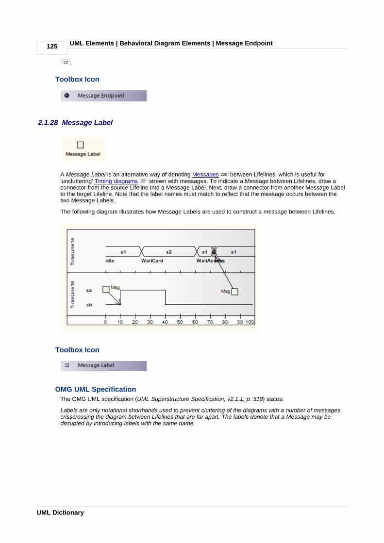
UML Elements | Behavioral Diagram Elements | Message Endpoint125
UML Dictionary
.
Toolbox Icon
2.1.28 Message Label
A Message Label is an alternative way of denoting Messages between Lifelines, which is useful for'uncluttering' Timing diagrams strewn with messages. To indicate a Message between Lifelines, draw aconnector from the source Lifeline into a Message Label. Next, draw a connector from another Message Labelto the target Lifeline. Note that the label names must match to reflect that the message occurs between thetwo Message Labels.
The following diagram illustrates how Message Labels are used to construct a message between Lifelines.
Toolbox Icon
OMG UML Specification
The OMG UML specification (UML Superstructure Specification, v2.1.1, p. 518) states:
Labels are only notational shorthands used to prevent cluttering of the diagrams with a number of messagescrisscrossing the diagram between Lifelines that are far apart. The labels denote that a Message may bedisrupted by introducing labels with the same name.
22
226
22

UML Elements | Behavioral Diagram Elements | Note 126
© 1998-2010 Sparx Systems Pty Ltd
2.1.29 Note
A Note element is a textual annotation that can be attached to a set of elements of any other type. Theattachment is created separately, using a Notelink connector. Both Note and Notelink are available in anyEnterprise Architect diagram, through the Common pages of the Enterprise Architect UML Toolbox (see UsingEnterprise Architect - UML Modeling Tool).
A Note is also called a Comment.
A Constraint is a form of Note, identifying a constraint on other elements. As for a Note, you can connect theConstraint element to other elements using a Notelink connector. This element is just a means of documentingthe fact that there are constraints; it has no impact on the other elements. You define the types of constraint inthe project reference data (see UML Model Management), apply them to the element in the element Propertiesdialog (see UML Modeling with Enterprise Architect – UML Modeling Tool), and manage them through theScenarios & Requirements window (see Using Enterprise Architect - UML Modeling Tool).
Toolbox Icon
OMG UML Specification
The OMG UML specification (UML Superstructure Specification, v2.1.1, p. 59) states:
A comment gives the ability to attach various remarks to elements. A comment carries no semantic force, butmay contain information that is useful to a modeler.
A comment can be owned by any element.
2.1.30 Partition
Activity Partitions are used to logically organize an Activity . They do not affect the token flow of anActivity diagram , but help structure all or parts of the view.
The following example depicts the partitioning between the Classes Process Payment and Order Processor.
230
93 90
5

UML Elements | Behavioral Diagram Elements | Partition127
UML Dictionary
The Partition orientation defaults to horizontal. To turn it into a vertical Partition, right-click on it and select the Advanced | Vertical Partition context menu option.
You can neatly align and join the Activity Partitions on a diagram using the element context menu Dockableoption. For Partitions, the option defaults to selected (see UML Modeling with Enterprise Architect - UMLModeling Tool).
Toolbox Icon
OMG UML Specification
The OMG UML specification (UML Superstructure Specification, v2.1.1, p. 341) states:
Partitions divide the nodes and edges to constrain and show a view of the contained nodes. Partitions canshare contents. They often correspond to organizational units in a business model. They may be used toallocate characteristics or resources among the nodes of an activity.
The OMG UML specification (UML Superstructure Specification, v2.1.1, p. 341) also states:
An activity partition is a kind of activity group for identifying actions that have some characteristic in common.
2.1.31 Receive
A Receive element is used to define the acceptance or receipt of a request, in an Activity diagram .Movement from a Receive element occurs only once receipt is fulfilled according to its specification. TheReceive element comes in two forms:
· Accept Event Action element (pennant shape)
· Accept Time Event Action element (hourglass shape)
The following example reflects a payment process on an order. Upon receiving the payment (from RequestPayments, a Send element), the payment is confirmed and the flow continues to ship the order.
5
129

UML Elements | Behavioral Diagram Elements | Receive 128
© 1998-2010 Sparx Systems Pty Ltd
See UML Superstructure Specification, v2.1.1, figure 12.26, p. 312.
To depict an Accept Time Event, use the standard Receive element from the Enterprise Architect UML Toolbox. Right-click on this element, and select the Advanced | Accept Time Event context menu option.The following example shows the hourglass-shaped Accept Time Event Action:
See UML Superstructure Specification, v2.1.1, figure 12.27, p. 312.
Toolbox Icon
OMG UML Specification
The OMG UML specification (UML Superstructure Specification, v2.1.1, p. 239) states:
AcceptEventAction is an action that waits for the occurrence of an event meeting specified conditions.
2.1.32 Region
Enterprise Architect supports two types of Region element:
· Expansion Region
· Interruptible Activity Region
When you add a Region element to an Activity diagram , the following prompt appears. You use this toselect the Region type.
107
121
5

UML Elements | Behavioral Diagram Elements | Region129
UML Dictionary
Toolbox Icon
2.1.33 Send
The Send element is used to depict the action of sending a signal, in an Activity diagram . It is the oppositeof a Receive element.
The following example shows an order being processed, where a signal is sent to fill the processed order and,upon creation of the resulting invoice, a notification is sent to the customer.
See UML Superstructure Specification, v2.1.1, figure 12.132, p. 408.
Toolbox Icon
OMG UML Specification
The OMG UML specification (UML Superstructure Specification, v2.1.1, p. 285) states:
SendObjectAction is an action that transmits an object to the target object, where it may invoke behavior suchas the firing of state machine transitions or the execution of an activity. The value of the object is available tothe execution of invoked behaviors. The requestor continues execution immediately. Any reply message isignored and is not transmitted to the requestor.
2.1.34 State
A State represents a situation where some invariant condition holds; this condition can be static (waiting for anevent) or dynamic (performing a set of activities). State modeling is usually related to Classes , anddescribes the enableable states a Class or element can be in and the transitions that enable the element tomove there. There are two types of State: Simple States and Composite States , both created from theState element from the Enterprise Architect UML Toolbox.
Furthermore, there are pseudo-states , resembling some aspect of a State but with a pre-definedimplication. Pseudo-states model complex transitional paths, and classify common State Machinebehavior.
5
127
152
130
13
9

UML Elements | Behavioral Diagram Elements | State 130
© 1998-2010 Sparx Systems Pty Ltd
You can define entry, internal and exit actions for a State using operations (see UML Modeling with EnterpriseArchitect - UML Modeling Tool).
If a State element has features such as attributes or operations, the depiction of the element in a diagram hasa line under the element name. This line persists if the features are hidden. The line also displays if the ShowState Compartment checkbox is selected on the Objects page of the Options dialog (Tools | Options |Objects).
Toolbox Icon
OMG UML Specification
The OMG UML specification (UML Superstructure Specification, v2.1.1, p. 546) states:
A state models a situation during which some (usually implicit) invariant condition holds. The invariant mayrepresent a static situation such as an object waiting for some external event to occur. However, it can alsomodel dynamic conditions such as the process of performing some activity (i.e., the model element underconsideration enters the state when the activity commences and leaves it as soon as the activity iscompleted).
2.1.34.1 Composite State
Composite States are composed within the State Machine diagram by expanding a State element,adding Regions if applicable, and dragging further State elements, related elements and connectors withinits boundaries. The internal State elements are then referred to as Sub-states.
(You can also define a State element, as with many other types of element, as a composite element ; thisthen has a hyperlink to a child diagram that can be another State Machine diagram or other type of diagramelsewhere in the model.)
Composite States can be orthogonal, if Regions are created. If a Composite State is orthogonal, its entrydenotes that a single Sub-state is concurrently active in all Regions. The hierarchical nesting of CompositeStates, coupled with Region use, generates a situation of multiple States concurrently active; this situation isreferred to as the active State configuration.
9 129
12
180

UML Elements | Behavioral Diagram Elements | State131
UML Dictionary
OMG UML Specification
The OMG UML specification (UML Superstructure Specification, v2.1.1, p. 478) states:
A composite state either contains one region or is decomposed into two or more orthogonal regions. Eachregion has a set of mutually exclusive disjoint subvertices and a set of transitions. A given state may only bedecomposed in one of these two ways.
Any state enclosed within a region of a composite state is called a substate of that composite state. It is calleda direct substate when it is not contained by any other state; otherwise it is referred to as an indirect substate.
Each region of a composite state may have an initial pseudostate and a final state. A transition to theenclosing state represents a transition to the initial pseudostate in each region. A newly-created object takesits topmost default transitions, originating from the topmost initial pseudostates of each region.
A transition to a final state represents the completion of activity in the enclosing region. Completion of activityin all orthogonal regions represents completion of activity by the enclosing state and triggers a completionevent on the enclosing state. Completion of the topmost regions of an object corresponds to its termination.

UML Elements | Behavioral Diagram Elements | State/Continuation 132
© 1998-2010 Sparx Systems Pty Ltd
2.1.35 State/Continuation
The State/Continuation element serves two different purposes for Interaction (Sequence ) diagrams, asState Invariants and Continuations . Enterprise Architect prompts you to identify the purpose when youcreate the element.
Toolbox Icon
2.1.35.1 Continuation
A Continuation is used in seq and alt Combined Fragments , to indicate the branches of continuation anoperand follows. To indicate a continuation, end an operand with a Continuation, and indicate the continuationbranch with a matching Continuation (same name) preceding the Interaction Fragment.
You create a Continuation by dragging the State/Continuation element onto the diagram from theInteraction Elements page of the Enterprise Architect UML Toolbox.
For the following continuation example, an alt Combined Fragment has Continuations pathSucc and pathFail.These Continuations are located within the Interaction Occurrence ConnHandler, which has subsequentevents based on the continuation.
39
134 132
96
132
119

UML Elements | Behavioral Diagram Elements | State/Continuation133
UML Dictionary
The following diagram shows the interaction referenced by the Interaction Occurrence.

UML Elements | Behavioral Diagram Elements | State/Continuation 134
© 1998-2010 Sparx Systems Pty Ltd
OMG UML Specification
The OMG UML specification (UML Superstructure Specification, v2.1.1, p. 474) states:
A Continuation is a syntactic way to define continuations of different branches of an AlternativeCombinedFragment. Continuation is intuitively similar to labels representing intermediate points in a flow ofcontrol.
The OMG UML specification (UML Superstructure Specification, v2.1.1, p. 474) also states:
Continuations have semantics only in connection with Alternative CombinedFragments and (weak)sequencing.
If an InteractionOperand of an Alternative CombinedFragment ends in a Continuation with name (say) X, onlyInteractionFragments starting with the Continuation X (or no continuation at all) can be appended.
2.1.35.2 State Invariant
A State Invariant is a condition applied to a Lifeline , which must be fulfilled for the Lifeline to exist. Youcreate a State Invariant by dragging the State/Continuation element onto the diagram from the InteractionElements page of the Enterprise Architect UML Toolbox.
The following diagram illustrates a State Invariant.
When a State Invariant is moved near to a Lifeline, it snaps to the center. If the sequence object is draggedleft or right, the State Invariant moves with it.
OMG UML Specification
The OMG UML specification (UML Superstructure Specification, v2.1.1, p. 502) states:
A StateInvariant is a runtime constraint on the participants of the interaction. It may be used to specify avariety of different kinds of constraints, such as values of attributes or variables, internal or external states,and so on.
A StateInvariant is an InteractionFragment and it is placed on a Lifeline.
123
132

UML Elements | Behavioral Diagram Elements | State Lifeline135
UML Dictionary
2.1.36 State Lifeline
A Lifeline is the path an object takes across a measure of time, as indicated by the x-axis. There are twosorts: State Lifelines (defined here) and Value Lifelines , both used in Timing diagrams .
A State Lifeline follows discrete transitions between states, which are defined along the y-axis of the timeline.Any transition has optional attributes of timing constraints, duration constraints and observations. An exampleof a State Lifeline is shown below:
See UML Superstructure Specification, v2.1.1, figure 14.29, p. 519.
A State Lifeline consists of a set of transition points. Each transition point can be defined with the followingproperties:
Property Description
At time Specifies the starting time for a change of state.
Transition to Indicates the state to which the lifeline changes.
Event Describes the occurring event.
Timing constraints Refers to the time taken for a state to change within a lifeline, or the time taken totransmit a message (e.g. t..t+3).
Timing observations Provides information on the time of a state change or sent message.
Duration constraints Pertains to a lifeline's period at a particular state. The constraint could beinstigated by a change of state within a lifeline, or that lifeline's receipt of amessage.
Duration observations Indicates the interval of a lifeline at a particular state, begun from a change instate or message receipt.
In the example diagram above, the OK transition point has these properties:
149 22

UML Elements | Behavioral Diagram Elements | State Lifeline 136
© 1998-2010 Sparx Systems Pty Ltd
Property Value
At Time 18 ms
Transition to Idle
Event OK
Timing constraints t..t+3
Timing observations –
Duration constraints –
Duration observations –
Toolbox Icon
OMG UML Specification
The OMG UML specification (UML Superstructure Specification, v2.1.1, p. 518) states:
This is the state of the classifier or attribute, or some testable condition, such as an discrete enumerablevalue.
It is also permissible to let the state-dimension be continuous as well as discrete. This is illustrative forscenarios where certain entities undergo continuous state changes, such as temperature or density.
2.1.37 State Machine
A State Machine element is a container for groups of related State elements. You can create sections of aState Machine diagram, showing the organization of the inter-related State elements, and enclose eachsection in a State Machine element. You can also create Regions on a State Machine Element.
Toolbox Icon
2.1.38 Structured Activity
Structured Activity elements are used in Activity diagrams . A Structured Activity is an activity node that canhave subordinate nodes as an independent Activity Group. No other Activities or their side effects shouldinterfere with this Activity's processing.
12
5

UML Elements | Behavioral Diagram Elements | Structured Activity137
UML Dictionary
Enterprise Architect provides two forms of Structured Activity - basic and specialized. It also applies themechanism for creating Structured Activities to creating composite Activity elements quickly and simply.
The two basic Structured Activities are:
· Structured Activity Node - represents an ordered arrangement of executable Activity nodes (Actions,Decisions, Merges and so on) that can include branched and nested nodes; this is the base element fromwhich the other types of Structured Activity are derived
· Sequential Node - represents a sequential arrangement of executable Activity nodes.
The two specialized Structured Activities are used to effectively model discreet patterns within an activitygraph, defined in Clauses or Partitions:
· Conditional node - represents an arrangement of Actions and Activities where choice determines whichActivities are performed
· Loop node - represents a sequence of Actions and Activities that are - or can be - repeated on thesame object.
Note:
All four Structured Activity Nodes are created as composite elements . However, for the Loop Node andConditional Node elements you must create the child element structure on the parent diagram within thenode element itself, as for a Composite State . You cannot develop the partitioned structure of the nodeson a child diagram.
For this reason, the Show Composite Diagram facility is not available for the Loop Node and ConditionalNode. It is also not available on the Structured Activity Node, as this is the base element for the Loop andConditional Nodes. You can, however, use the two basic nodes as composite elements, and display the childdiagram structure on the parent Sequential node.
When you create a Structured Activity, by selecting the icon from the Activity page of the Enterprise ArchitectUML Toolbox, the following context menu displays:
The first two options specifically create a Loop or Conditional Node. The Other option displays the NewStructured Activity dialog, on which you can select to create any of the four nodes, or a simple CompositeActivity element.
Toolbox Icon
90
138
138
139
139
180
130

UML Elements | Behavioral Diagram Elements | Structured Activity 138
© 1998-2010 Sparx Systems Pty Ltd
OMG UML Specification
Structured Activity Node
The OMG UML specification (UML Superstructure Specification, v2.1.1, p. 409) states:
A structured activity node is an executable activity node that may have an expansion into subordinate nodesas an ActivityGroup. The subordinate nodes must belong to only one structured activity node, although theymay be nested.
A structured activity node represents a structured portion of the activity that is not shared with any otherstructured node, except for nesting.
Sequential Node
The OMG UML specification (UML Superstructure Specification, v2.1.1, p. 408) states:
A sequence node is a structured activity node that executes its actions in order.
Loop Node
The OMG UML specification (UML Superstructure Specification, v2.1.1, pp. 384-385) states:
A loop node is a structured activity node that represents a loop with setup, test, and body sections.
Each section is a well-nested subregion of the activity whose nodes follow any predecessors of the loop andprecede any successors of the loop. The test section may precede or follow the body section. The setupsection is executed once on entry to the loop, and the test and body sections are executed repeatedly until thetest produces a false value. The results of the final execution of the test or body are available after completionof execution of the loop.
Conditional Node
The OMG UML specification (UML Superstructure Specification, v2.1.1, p.355) states:
A conditional node is a structured activity node that represents an exclusive choice among some number ofalternatives.
A conditional node consists of one or more clauses. Each clause consists of a test section and a body section.When the conditional node begins execution, the test sections of the clauses are executed. If one or more testsections yield a true value, one of the corresponding body sections will be executed. If more than one testsection yields a true value, only one body section will be executed. The choice is nondeterministic unless thetest sequence of clauses is specified. If no test section yields a true value, then no body section is executed;this may be a semantic error if output values are expected from the conditional node.
2.1.38.1 Structured and Sequential Nodes
On a diagram, Structured and Sequential Activity Nodes have broken borders and composite diagram icons,as shown below:
To display the Activity diagram represented by a Structured or Sequential Activity Node element, double-clickon the element.
Structured Activity Node elements can point to child diagrams that themselves contain or consist of StructuredActivity elements; that is, the Structured Activity elements are nested, as shown in the section of ProjectBrowser below.

UML Elements | Behavioral Diagram Elements | Structured Activity139
UML Dictionary
2.1.38.2 Loop and Conditional Nodes
A Loop Structured Activity Node by default has Setup, Test and Body partitions. The Setup partition isexecuted once on entry to the Loop, and the Test and Body partitions are executed repeatedly until the Testproduces a false value. The results of the final execution of the Test or Body are available after execution ofthe Loop is complete.
A Conditional Structured Activity Node has a default Clause containing Test and Body partitions. FurtherClauses can be added if required.
The two elements are depicted on an Activity diagram as shown below:
You define the Loop or Condition nodes by dragging other Activity diagram elements from the Toolbox pageinto the appropriate partition of the element, and linking and organizing the structure as required. Theelements are aligned on the top left of the partition, so that resizing the node maintains the organization of thestructure within and between the partitions. If you try to shrink the node below the structure size, the nodeautomatically defaults to the 'best fit' size.
Conditional Node
When you create a Conditional Node, the element Properties dialog displays. Much of this you cancomplete as for any other element. However, for the Conditional Node the dialog also has a Condition tab, asshown below:
136

UML Elements | Behavioral Diagram Elements | Structured Activity 140
© 1998-2010 Sparx Systems Pty Ltd
Add an Action Pin as the Result for the node, clicking on the Add button to display the Select Pins dialog(a version of the Select <Item> dialog).
On creation, the Conditional Node automatically has one Clause containing a Decider and Body Output, anda Test partition and a Body partition. You can add further Clauses as required. For each Clause you also addan Action Pin for the Decider and for the Body Output. Click on the Save button to save the Clause definition.
The Select Pin dialog reveals only Output pins as appropriate to the context. If the required Action Pin doesnot already exist, you can click on the Add New button on the dialog to automatically create an Output pinunder the appropriate parent node.
For the Result and Body Output entries, you can check on the exact location of each Action Pin byright-clicking on the entry and selecting the Find in Project Browser context menu option.
The Nodes panel, by default, lists the Actions and Activities contained in the Test partition. Click on the Bodyradio button to list the elements contained in the Body partition. An element must be completely contained inthe Body partition to be listed there - if it overlaps with the Test partition in any way, it is treated as being partof the Test partition.
Add or Remove Clauses
To add another Clause, click on the Add button underneath the Clause(s) list. This inserts a new Clause in thelist, and identifies which is the preceding, or Predecessor, Clause and (if appropriate) which is the following, or
87

UML Elements | Behavioral Diagram Elements | Structured Activity141
UML Dictionary
Successor, Clause. The remaining fields in the Clause(s) panel are cleared to enable you to add Decider andBody Output Action Pins. New Test and Body partitions are immediately added to the element on thediagram, and you can populate these partitions with Activity elements, which are then identified in the Nodespanel.
To remove a Clause, highlight it in the list and click on the Delete button. This immediately removes theClause's corresponding partitions from the diagram, along with all their contained Activity elements. Removinga Clause from between two other Clauses adjusts the numerical order; for example, if Clause 2 is removedfrom between Clause 1 and Clause 3, Clause 3 is renamed as Clause 2, and any further Clauses are alsomoved up one place.
Loop Node
When you create a Loop Node, the element Properties dialog displays. Much of this you can complete asfor any other element. However, for the Loop Node the dialog also has a Loop tab, as shown below:
Add an Action Pin for each of the Decider, Loop Variable Input, Loop Variable, Body Output andResult fields for the node, in each case clicking on the Browse or Add button to display the Select Pins dialog(a version of the Select <Item> dialog). The Select ActionPin dialog reveals only Input pins (Loop VariableInput) or Output pins as appropriate to the context. If the required Action Pin does not already exist, you canclick on the Add New button on the dialog to automatically create the Input pin or an Output pin under theappropriate parent node.
136
87

UML Elements | Behavioral Diagram Elements | Structured Activity 142
© 1998-2010 Sparx Systems Pty Ltd
You can also check on the exact location of an existing Action Pin by right-clicking on the pin name andselecting the Find in Project Browser context menu option.
The Nodes panel, by default, lists the Actions and Activities contained in the Setup partition. Click on theBody or Test radio buttons to list the elements contained in the corresponding partitions. An element must becompletely contained in a partition to be listed there - if it overlaps with the partition above in any way, it istreated as being part of that partition.
2.1.39 Synch
A Synch state is useful for indicating that concurrent paths of a State Machine are synchronized. Afterbringing the paths to a synch state, the emerging transition indicates unison.
Toolbox Icon
2.1.40 System Boundary
A System Boundary element is a non-UML element used to define conceptual boundaries. You can useSystem Boundaries to help group logically related elements (from a visual perspective, not as part of the UMLmodel).
In the UML Superstructure Specification, v2.1.1, System Boundaries are described in the sections on UseCases , because the System Boundary is often used to indicate the application of a Use Case to anotherentity. In this context, the System Boundary:
· encloses the Use Case, and
· is associated with a classifier such as a Class , Component or Sub-system (Actor ) through theSelect <Item> dialog (see UML Modeling With Enterprise Architect - UML Modeling Tool).
By associating the System Boundary - and not the Use Case - with the classifier, the classifier is linked to theUse Case as a user, but not as an owner.
9
142
146
152 158 94

UML Elements | Behavioral Diagram Elements | System Boundary143
UML Dictionary
You can also define a Use Case as the classifier of a System Boundary element, to link the elementsenclosed in the System Boundary (such as parts of an Activity diagram) to their representation in a logicalUse Case. See http://www.sparxsystems.com.au/resources/map_uc.html.
The following properties of a System Boundary can be set: the name, the border style , and the number ofhorizontal or vertical swim lanes.
A System Boundary element can be marked as Selectable, using the element's context menu. When notselectable, you can click within the System Boundary space without activating or selecting the Boundary itself.This is useful when you have many elements within the Boundary and the Boundary makes their selectiondifficult.
Note:
A System Boundary can have an associated image that it displays instead of its default format. Use the Appearance | Alternate Image menu option to select an image. (See UML Modeling with EnterpriseArchitect – UML Modeling Tool.)
Toolbox Icon
OMG UML Specification
The OMG UML specification (UML Superstructure Specification, v2.1.1, p. 594) states:
If a subject (or system boundary) is displayed, the Use Case ellipse is visually located inside the systemboundary rectangle. Note that this does not necessarily mean that the subject classifier owns the containedUse Cases, but merely that the Use Case applies to that classifier.
144

UML Elements | Behavioral Diagram Elements | System Boundary 144
© 1998-2010 Sparx Systems Pty Ltd
2.1.40.1 Boundary Element Settings
Configure Boundary Elements
Boundary elements can be configured to display in different ways. The main differences are:
· Solid border
· Dotted border
· With horizontal or vertical 'swim lanes'; swim lanes are used to group elements in a vertical or horizontalcontext (for example, Client, Application and Database tiers could be represented in swim lanes).
2.1.41 Terminate
The Terminate pseudo-state indicates that upon entry of its pseudo-state, the State Machine'sexecution ends.
Toolbox Icon
13 9

UML Elements | Behavioral Diagram Elements | Trigger145
UML Dictionary
2.1.42 Trigger
A Trigger indicates an event that initiates an action (and might arise from completion of a previous action).You initially define a Trigger in one of four ways:
· As a property of a Transition relationship
· As a property of an Accept Event Action (on the Triggers tab of the element Properties dialog)
· As an event in a State Machine Table
· Directly, as a Trigger element, through the New Element dialog.
When you save the Trigger, it is added to the list of elements for the parent package in the Project Browser.You can then right-click on it and select the Properties context menu option to view and, if required, edit itsproperties as an element rather than as a property itself. Triggers created as events remain as Eventelements, whilst Triggers created in other ways are Trigger elements, with a Trigger tab in the Propertiesdialog.
Option Use to
Type If necessary, edit the type of trigger:
· Call - specifies that the event is a CallEvent, which sends a message to theassociated object by invoking an operation.
· Change - specifies that the event is a ChangeEvent, which indicates that thetransition is the result of a change in value of an attribute.
· Signal - specifies that the event is a SignalEvent, which corresponds to thereceipt of an asynchronous signal instance.
· Time - corresponds to a TimeEvent; which specifies a moment in time.
Specification Either type in the event instigating the Trigger, or click on the [ ... ] button and selectthe event (depending on the Type value).
Ports Click on the Add button and select the appropriate Port from the Select Port dialog.
236
79
19

UML Elements | Behavioral Diagram Elements | Trigger 146
© 1998-2010 Sparx Systems Pty Ltd
Option Use to
Notes:
· To create new Ports using the Select Port dialog, the Trigger should be createdas a child of a Class or Component element.
· To add several Ports at once, press [Ctrl] as you select each Port.
· To check the exact location of a Port, right-click on the Port name and select the Find in Project Browser context menu option.
You can also drag the Trigger element onto another diagram, although there are limited uses for the elementin that context.
This element is not the same as a Trigger Operation, which is an operation automatically executed as a resultof the modification of data in a database. (See Code Engineering Using UML Models.)
OMG UML Specification
The OMG UML specification (UML Superstructure Specification, v2.1.1, p. 456) states:
Events may cause execution of behavior (e.g., the execution of the effect activity of a transition in a statemachine). A trigger specifies the event that may trigger a behavior execution as well as any constraints on theevent to filter out events not of interest.
2.1.43 Use Case
A Use Case is a UML modeling element that describes how a user of the proposed system interacts with thesystem to perform a discrete unit of work. It describes and signifies a single interaction over time that hasmeaning for the end user (person, machine or other system), and is required to leave the system in acomplete state: the interaction either completed or rolled back to the initial state. A Use Case:
· Typically has requirements and constraints that describe the essential features and rules under which itoperates
· Can have an associated Sequence diagram illustrating behavior over time; who does what to whom,and when
· Typically has scenarios associated with it that describe the work flow over time that produces the endresult; alternative work flows (for example, to capture exceptions) are also enabled.
Note:
Use a Use Case diagram and model to build up the functional requirements and implementation details of thesystem.
The following is an example Use Case model:
39

UML Elements | Behavioral Diagram Elements | Use Case147
UML Dictionary
If extending a Use Case, you can specify the points of extension with Use Case Extension Points . Todisplay the attributes, operations or constraints of a Use Case on a diagram, use Rectangle Notation .
Enterprise Architect also provides two stereotyped Use Cases - the Test Case and the Business Use Case.
Toolbox Icon
OMG UML Specification
The OMG UML specification (UML Superstructure Specification, v2.1.1, p. 592) states:
A UseCase is a kind of behaviored classifier that represents a declaration of an offered behavior. Each UseCase specifies some behavior, possibly including variants, that the subject can perform in collaboration withone or more actors.
2.1.43.1 Use Case Extension Points
Use extension points to specify the point of an extended Use Case where an extending Use Case'sbehavior should be inserted. The specification text can be informal or precise to define the location of theextension point.
Note:
Conditions to apply the extending Use Case, and the extension point to use, should be attached as a note tothe extend relationship.
147
148
191
75
146

UML Elements | Behavioral Diagram Elements | Use Case 148
© 1998-2010 Sparx Systems Pty Ltd
To work with extension points, follow the steps below:
1. Right-click on the Use Case element. The context menu displays.
2. Select the Advanced | Edit Extension Points... menu option. The Use Case Extension Points dialogdisplays, listing defined points for that Use Case.
3. Select an extension point in the list and click on the appropriate button to edit or remove the extensionpoint, or to add a new one.
2.1.43.2 Rectangle Notation
You can display a Use Case using rectangle notation. This displays the Use Case in a rectangle, with anoval in the top right-hand corner. Any attributes, operations or constraints belonging to the Use Case areshown, in the same style as a Class .
To show a Use Case using rectangle notation, right-click on the Use Case object on the diagram and selectthe Advanced | Use Rectangle Notation context menu option. This setting only applies to the selected UseCase, and can be toggled on and off.
Note:
Actor elements can also be displayed using rectangle notation.
146
152
94

UML Elements | Behavioral Diagram Elements | Value Lifeline149
UML Dictionary
2.1.44 Value Lifeline
A Lifeline is the path an object takes across a measure of time, indicated by the x-axis. There are two sorts:Value Lifelines (defined here) and State Lifelines , both used in Timing diagrams .
A Value Lifeline shows the Lifeline's state across the diagram, with parallel lines indicating a steady state. Across between the lines indicates a transition or change in state.
An example of a Value Lifeline is shown below:
See UML Superstructure Specification, v2.1.1, Figure 14.30, p. 520.
A Value Lifeline consists of a set of transition points. Each transition point can be defined with the followingproperties:
Property Description
At time Specifies the starting time for a change of state.
Transition to Indicates the state to which the Lifeline will change.
Event Describes the occurring event.
Timing constraints Refers to the time taken for a state to change within a Lifeline, or the time taken totransmit a message.
Timing observations Provides information on the time of a state change or sent message.
Duration constraints Pertains to a Lifeline's period at a particular state. The constraint could beinstigated by a change of state within a Lifeline, or that Lifeline's receipt of amessage.
Duration observations Indicates the interval of a Lifeline at a particular state, begun from a change instate or message receipt.
In the example diagram above, the 10ms transition point has these properties:
Property Text
At Time 10ms
Transition to Waitcard
Event Switch
Timing constraints –
135 22

UML Elements | Behavioral Diagram Elements | Value Lifeline 150
© 1998-2010 Sparx Systems Pty Ltd
Property Text
Timing observations –
Duration constraints d..3*d
Duration observations –
Toolbox Icon
OMG UML Specification
The OMG UML specification (UML Superstructure Specification, v2.1.1, p. 518) states:
Shows the value of the connectable element as a function of time. Value is explicitly denoted as text. Crossingreflects the event where the value changed.
2.2 Structural Diagram Elements
The following figure illustrates the main UML elements that are used in Structural Diagrams . For moreinformation on using each element, click on the element name in this list:
· Actor , Artifact
· Class , Collaboration , Collaboration Occurrence , Component
· Data Type , Deployment Specification , Document Artifact
· Enumeration , Execution Environment , Expose Interface
· Information Item , Interface
· Node , Note
· Object
· Package , Part , Port , Primitive
· Qualifiers
· Signal
Note:
Actor, Collaboration, Note, Object and Package elements are used in both Behavioral diagrams andStructural diagrams.
78 54
94 151
152 156 157 158
159 160 161
162 162 163
163 164
165 126
165
168 168 169 173
173
178

UML Elements | Structural Diagram Elements | 151
UML Dictionary
2.2.1 Artifact
An Artifact is any physical piece of information used or produced by a system, represented in a DeploymentDiagram . Artifacts can have associated properties or operations, and can be instantiated or associatedwith other Artifacts. Examples of Artifacts include model files, source files, database tables, development
62

UML Elements | Structural Diagram Elements | Artifact 152
© 1998-2010 Sparx Systems Pty Ltd
deliverables or support documents. The files represented by the Artifact are listed on the Files tab of theelement Properties dialog.
To open the files represented by the Artifact, click on the element on the diagram and press [Ctrl]+[E]. Eachfile is opened either on a separate tab in the Diagram View workspace (if the file can be opened withinEnterprise Architect) or in the default Windows viewer/editor for the file type (if the file cannot be opened withinEnterprise Architect).
Files can also be launched individually from the Files tab (opening in the Windows default editor), as forelements of any other type that have associated files.
Toolbox Icon
Create Artifact For External File
You can also create an Artifact element on a diagram from an external file, by clicking on the file in a file list(such as Windows Explorer) or on your Desktop and dragging it onto the diagram. A short context menudisplays with two options - Hyperlink and Artifact.
Click on the Artifact option to create the element on the diagram. The Properties dialog displays, and you candefine the name or other properties as required. Click on the OK button, and then open the Properties dialogagain and click on the Files tab. The file pathname is listed in the Files panel.
OMG UML Specification
The OMG UML specification (UML Superstructure Specification, v2.1.1, p. 201) states:
An Artifact defined by the user represents a concrete element in the physical world. A particular instance (or'copy') of an artifact is deployed to a node instance. Artifacts may have composition associations to otherartifacts that are nested within it. For instance, a deployment descriptor artifact for a component may becontained within the artifact that implements that component. In that way, the component and its descriptor aredeployed to a node instance as one artifact instance.
2.2.2 Class
A Class is a representation of objects that reflects their structure and behavior within the system. It is atemplate from which actual running instances are created, although a Class can be defined either to control itsown execution or as a template or parameterized Class that specifies parameters that must be definedby any binding Class.
A Class can have attributes (data) and methods (operations or behavior) - see UML Modeling with EnterpriseArchitect – UML Modeling Tool. Classes can inherit characteristics from parent Classes and delegate behaviorto other Classes. Class models usually describe the logical structure of the system and are the building blocksfrom which components are built.
The top section of a Class, as illustrated below, shows the attributes (or data elements) associated with theClass. These hold the 'state' of an object at run-time. If the information is saved to a data store and can bereloaded, it is termed 'persistent'. The lower section contains the Class operations (or methods at run-time).Operations describe the behavior a Class offers to other Classes, and the internal behavior it has (privatemethods).
Class elements are generally used in Class diagrams and Composite Structure diagrams .
Enterprise Architect also supports a number of stereotyped Class elements to represent various entities in
153 154
56 59

UML Elements | Structural Diagram Elements | Class153
UML Dictionary
web-page modeling . A Class can also be integrated with an Associate connector to form anAssociation Class , to allow the Associate connector to have operations and attributes that define certaintypes of UML relationship.
Toolbox Icon
OMG UML Specification
The OMG UML specification (UML Superstructure Specification, v2.1.1, pp. 52-53) states:
The purpose of a class is to specify a classification of objects and to specify the features that characterize thestructure and behavior of those objects.
Objects of a class must contain values for each attribute that is a member of that class, in accordance with thecharacteristics of the attribute, for example its type and multiplicity.
When an object is instantiated in a class, for every attribute of the class that has a specified default, if an initialvalue of the attribute is not specified explicitly for the instantiation, then the default value specification isevaluated to set the initial value of the attribute for the object.
Operations of a class can be invoked on an object, given a particular set of substitutions for the parameters ofthe operation. An operation invocation may cause changes to the values of the attributes of that object. It mayalso return a value as a result, where a result type for the operation has been defined. Operation invocationsmay also cause changes in value to the attributes of other objects that can be navigated to, directly orindirectly, from the object on which the operation is invoked, to its output parameters, to objects navigablefrom its parameters, or to other objects in the scope of the operation's execution. Operation invocations mayalso cause the creation and deletion of objects.
2.2.2.1 Active Classes
An Active Class indicates that, when instantiated, the Class controls its own execution. Rather than beinginvoked or activated by other objects, it can operate standalone and define its own thread of behavior.
To define an Active Class in Enterprise Architect, follow the steps below:
1. Highlight a Class, and display its Properties dialog.
2. Click on the Advanced button.
3. Select the Is Active checkbox.
4. Click on the OK button to save the details.
194 199
200
152

UML Elements | Structural Diagram Elements | Class 154
© 1998-2010 Sparx Systems Pty Ltd
OMG UML Specification
The OMG UML specification (UML Superstructure Specification, v2.1.1, p. 438) states:
An active object is an object that, as a direct consequence of its creation, commences to execute its classifierbehavior, and does not cease until either the complete behavior is executed or the object is terminated bysome external object. (This is sometimes referred to as "the object having its own thread of control.") Thepoints at which an active object responds to communications from other objects is determined solely by thebehavior of the active object and not by the invoking object. If the classifier behavior of an active objectcompletes, the object is terminated.
2.2.2.2 Parameterized Classes (Templates)
Enterprise Architect supports template or parameterized Classes, which specify parameters that must bedefined by any binding Class . A template Class enables its functionality to be reused by any bound Class.If a default value is specified for a parameter, and a binding Class doesn't provide a value for that parameter,the default is used. Parameterized Classes are commonly implemented in C++.
Enterprise Architect imports and generates templated Classes for C++. Template Classes are shown with theparameters in a dashed outline box in the upper right corner of a Class.
To create a parameterized Class, follow the steps below:
1. Display the Properties dialog for a Class.
2. Select the Details tab.
152

UML Elements | Structural Diagram Elements | Class155
UML Dictionary
3. In the Type field, click on the drop-down arrow and select Parameterized.
For an instantiated template, select Instantiated and add the arguments in the Arguments field.
4. Click on the Add button and define the required parameters in the Class Parameter dialog.

UML Elements | Structural Diagram Elements | Class 156
© 1998-2010 Sparx Systems Pty Ltd
Notation Example
OMG UML Specification
The OMG UML specification (UML Superstructure Specification, v2.1.1, p. 622) states:
A template is a parameterized element that can be used to generate other model elements usingTemplateBinding relationships. The template parameters for the template signature specify the formalparameters that will be substituted by actual parameters (or the default) in a binding.
2.2.3 Collaboration
A Collaboration defines a set of cooperating roles and their connectors. These are used to collectivelyillustrate a specific functionality, in a Composite Structure diagram . A Collaboration should specify only theroles and attributes required to accomplish a specific task or function. Although in practice a behavior and itsroles could involve many tangential attributes and properties, isolating the primary roles and their requisitessimplifies and clarifies the behavior, as well as providing for reuse. A Collaboration often implements a patternto apply to various situations.
The following example illustrates an Install Collaboration, with three roles (Objects ) connected as shown.The process for this Collaboration can be demonstrated by attaching an Interaction diagram (Sequence ,Timing , Communication or Interaction Overview ).
59
165
41
22 49 52

UML Elements | Structural Diagram Elements | Collaboration157
UML Dictionary
To understand referencing a Collaboration in a specific situation, see the Collaboration Occurrence topic.
Enterprise Architect supports a stereotyped Collaboration to represent a Business Use Case Realization inbusiness modeling.
Toolbox Icon
OMG UML Specification
The OMG UML specification (UML Superstructure Specification, v2.1.1, p. 171) states:
A collaboration describes a structure of collaborating elements (roles), each performing a specialized function,which collectively accomplish some desired functionality. Its primary purpose is to explain how a system worksand, therefore, it typically only incorporates those aspects of reality that are deemed relevant to theexplanation.
2.2.4 Collaboration Occurrence
Use a Collaboration Occurrence to apply a pattern defined by a Collaboration to a specific situation, in aComposite Structure diagram .
The following example uses an occurrence, NWServer, of the Collaboration Install, to define the installationprocess of a network scanner. This process can be defined by an interaction attached to the Collaboration.(See the Collaboration topic for a representation of the Install Collaboration.)
157
75
59
156

UML Elements | Structural Diagram Elements | Collaboration Occurrence 158
© 1998-2010 Sparx Systems Pty Ltd
To create a Collaboration Occurrence, drag the required Collaboration from the Project Browser onto thediagram and, on the Paste Element dialog, select the Paste as Link radio button.
OMG UML Specification
The OMG UML specification (UML Superstructure Specification, v2.1.1, p. 173) refers to a CollaborationOccurrence as a Collaboration Use, and states:
A collaboration use represents one particular use of a collaboration to explain the relationships between theproperties of a classifier. A collaboration use shows how the pattern described by a collaboration is applied ina given context, by binding specific entities from that context to the roles of the collaboration. Depending onthe context, these entities could be structural features of a classifier, instance specifications, or even roles insome containing collaboration. There may be multiple occurrences of a given collaboration within a classifier,each involving a different set of roles and connectors. A given role or connector may be involved in multipleoccurrences of the same or different collaborations.
2.2.5 Component
A Component is a modular part of a system, whose behavior is defined by its provided and required interfaces;the internal workings of the Component should be invisible and its usage environment-independent. Sourcecode files, DLLs, Java beans and other artifacts defining the system can be manifested in Components.
A Component can be composed of multiple Classes , or Components pieced together. As smallerComponents come together to create bigger Components, the eventual system can be modeled, building-block style, in Component diagrams . By building the system in discrete Components, localization of dataand behavior enables decreased dependency between Classes and Objects , providing a more robust andmaintainable design.
152
65
165

UML Elements | Structural Diagram Elements | Component159
UML Dictionary
Toolbox Icon
OMG UML Specification
The OMG UML specification (UML Superstructure Specification, v2.1.1, p. 148) states:
A component represents a modular part of a system that encapsulates its contents and whose manifestation isreplaceable within its environment.
A component defines its behavior in terms of provided and required interfaces. As such, a component servesas a type whose conformance is defined by these provided and required interfaces (encompassing both theirstatic as well as dynamic semantics).
2.2.6 Data Type
A Data Type is a specific kind of classifier, similar to a Class except that a Data Type cannot own sub DataTypes, and instances of a Data Type are identified only by their value. For example, an instance of a PersonClass is a Helen object, but an instance of an Integer Data Type is 12.
All copies of an instance of a Data Type, and any instances of that Data Type with the same value, areconsidered to be the same instance. That is, instances of Helen are not necessarily the same Helen, but all 12s are the same 12. For example, the 12 on a watch face is exactly the same integer as the number of monthsin a year.
Instances of a Data Type that have attributes (that is, are instances of a structured Data Type) are consideredto be the same if the structure is the same and the values of the corresponding attributes are the same. If aData Type has attributes, instances of that Data Type contain attribute values matching the attributes.
A typical use of Data Types would be to represent programming language primitive types or CORBA basictypes. For example, integer and string types are often treated as Data Types.
A Data Type is denoted by a rectangle with the keyword «dataType», as above or, when it is referenced by (forexample) an attribute, by a string containing the name of the Data Type, as below:
Toolbox Icon
152

UML Elements | Structural Diagram Elements | Deployment Spec 160
© 1998-2010 Sparx Systems Pty Ltd
2.2.7 Deployment Spec
A Deployment Specification (spec) specifies parameters guiding deployment of an artifact, as is necessarywith most hardware and software technologies. A specification lists those properties that must be defined fordeployment to occur, as represented in a Deployment diagram . An instance of this specification specifiesthe values for the parameters; a single specification can be instantiated for multiple artifacts.
These specifications can be extended by certain component profiles. Examples of standard Tagged Valuesthat a profile might add to a Deployment Specification are «concurrencyMode» with Tagged Values {thread,process, none} or «transactionMode» with Tagged Values {transaction, nestedTransaction, none}.
The following example depicts the artifact RepositoryApp deployed on the server node, as per thespecifications of RepositoryApp, instantiated from the Deployment Specification SystemSpec.
Toolbox Icon
OMG UML Specification
The OMG UML specification (UML Superstructure Specification, v2.1.1, p. 206) states:
A deployment specification specifies a set of properties that determine execution parameters of a componentartifact that is deployed on a node. A deployment specification can be aimed at a specific type of container. Anartifact that reifies or implements deployment specification properties is a deployment descriptor.
62

UML Elements | Structural Diagram Elements | Device161
UML Dictionary
2.2.8 Device
A Device is a physical electronic resource with processing capability upon which Artifacts can be deployedfor execution, as represented in a Deployment diagram . Complex Devices can consist of other devices;that is, a Device can be a nested element, where a physical machine is decomposed into its elements eitherthrough namespace ownership or through attributes that are typed by Devices.
Toolbox Icon
OMG UML Specification
The OMG UML specification (UML Superstructure Specification, 10.3.7, v2.1.1, p. 207) states:
In the metamodel, a Device is a subclass of Node.
2.2.9 Document Artifact
A Document Artifact is an artifact having a stereotype of «document». You create the Document Artifact ona Component, Documentation or Deployment diagram, and associate it with an RTF document. Double-clickon the element to display the Linked Document Editor. See Linked Documents in UML Modeling withEnterprise Architect – UML Modeling Tool. When you have created the linked document, the DocumentArtifact element on the diagram shows an A symbol in the bottom right corner.
Toolbox Icon
151
62
151

UML Elements | Structural Diagram Elements | Enumeration 162
© 1998-2010 Sparx Systems Pty Ltd
2.2.10 Enumeration
An Enumeration is a data type, whose instances can be any of a number of user-defined enumeration literals.It is possible to extend the set of applicable enumeration literals in other packages or profiles. You createEnumerations in Class or Package diagrams , and in diagrams developed from the Metamodel pagesof the Enterprise Architect UML Toolbox (see Using Enterprise Architect - UML Modeling Tool).
Toolbox Icon
OMG UML Specification
The OMG UML specification (UML Superstructure Specification, v2.1.1, p. 69) states:
An enumeration is a data type whose values are enumerated in the model as enumeration literals.
2.2.11 Execution Environment
An Execution Environment is a node that offers an execution environment for specific types of components that are deployed on it in the form of executable artifacts . This is depicted in a Deployment diagram.
Execution Environments can be nested; for example, a database Execution Environment can be nested in anoperating system Execution Environment. Components of the appropriate type are then deployed to specificExecution Environment nodes.
Toolbox Icon
OMG UML Specification
The OMG UML specification (UML Superstructure Specification, v2.1.1, p. 210 states:
... an ExecutionEnvironment is ... usually part of a general Node, representing the physical hardwareenvironment on which the ExecutionEnvironment resides. In that environment, the ExecutionEnvironmentimplements a standard set of services that Components require at execution time (at the modeling level theseservices are usually implicit). For each component Deployment, aspects of these services may be determinedby properties in a DeploymentSpecification for a particular kind of ExecutionEnvironment.
56 55
165
158 151
62

UML Elements | Structural Diagram Elements | Expose Interface163
UML Dictionary
2.2.12 Expose Interface
The Expose Interface element is a graphical method of depicting the required or supplied interfaces of aComponent , Class or Part , in a Component or Composite Structure diagram. It justidentifies the fact that the element provides or requires an interface; to depict the fact that the providedinterface is used, or the required interface provided, by another element use the Assembly connector.
The Expose Interface element must be attached to the Class or Component element, and it becomes a childelement of that Class or Component; it cannot exist independently. You can attach more than one ExposeElement to another element.
When you create the Expose Interface element, a dialog displays in which you enter a name for the elementand specify whether it represents a required interface or a provided interface.
Toolbox Icon
2.2.13 Information Item
An Information Item represents an abstraction of data. It is used in Activity , Analysis and Objectdiagrams. An Information Item is also represented by an Information Flow connector.
Toolbox Icon
OMG UML Specification
The OMG UML specification (UML Superstructure Specification, v2.1.1, p. 608) states:
An information item is an abstraction of all kinds of information that can be exchanged between objects. It is a
164
158 152 168 65 59
199
5 67 58
208

UML Elements | Structural Diagram Elements | Information Item 164
© 1998-2010 Sparx Systems Pty Ltd
kind of classifier intended for representing information at a very abstract way, one which cannot beinstantiated.
One purpose of information items is to be able to define preliminary models, before having made detailedmodeling decisions on types or structures. One other purpose of information items and information flows is toabstract complex models by a less precise but more general representation of the information exchangedbetween entities of a system.
2.2.14 Interface
An Interface is a specification of behavior (or contract) that implementers agree to meet. By implementing anInterface, Classes are guaranteed to support a required behavior, which enables the system to treat non-related elements in the same way; that is, through the common interface. You also use Interfaces in a Composite Structure diagram.
Interfaces are drawn in a similar way to a Class , with operations specified, as shown below. They can alsobe drawn as a circle with no explicit operations detailed. Right-click on the element and select the Use CircleNotation context menu option to switch between styles. Realization connectors to an Interface drawn as acircle are drawn as a solid line without target arrows.
Note:
An Interface cannot be instantiated (that is, you cannot create an object from an Interface). You must create aClass that 'implements' the Interface specification, and in the Class body place operations for each of theInterface operations. You can then instantiate the Class.
Toolbox Icon
OMG UML Specification
The OMG UML specification (UML Superstructure Specification, v2.1.1, p. 88) states:
An interface is a kind of classifier that represents a declaration of a set of coherent public features andobligations. An interface specifies a contract; any instance of a classifier that realizes the interface must fulfillthat contract. The obligations that may be associated with an interface are in the form of various kinds ofconstraints (such as pre- and post-conditions) or protocol specifications, which may impose orderingrestrictions on interactions through the interface.
Since interfaces are declarations, they are not instantiable. Instead, an interface specification is implementedby an instance of an instantiable classifier, which means that the instantiable classifier presents a publicfacade that conforms to the interface specification. Note that a given classifier may implement more than oneinterface and that an interface may be implemented by a number of different classifiers.
56
59
152
233

UML Elements | Structural Diagram Elements | Node165
UML Dictionary
2.2.15 Node
A Node is a physical piece of equipment on which the system is deployed, such as a workgroup server orworkstation. A Node usually hosts components and other executable pieces of code, which again can beconnected to particular processes or execution spaces. Typical Nodes are client workstations, applicationservers, mainframes, routers and terminal servers.
Nodes are used in Deployment diagrams to model the deployment of a system, and to illustrate thephysical allocation of implemented artifacts. They are also used in web modeling, from dedicated webmodeling pages in the Enterprise Architect UML Toolbox (see Using Enterprise Architect - UML Modeling Tool).
Toolbox Icon
OMG UML Specification
The OMG UML specification (UML Superstructure Specification, v2.1.1, p. 213) states:
In the metamodel, a Node is a subclass of Class. It is associated with a Deployment of an Artifact. It is alsoassociated with a set of Elements that are deployed on it. This is a derived association in that thesePackageableElements are involved in a Manifestation of an Artifact that is deployed on the Node. Nodes mayhave an internal structure defined in terms of parts and connectors associated with them for advancedmodeling applications.
2.2.16 Object
An Object is a particular instance of a Class at run time. For example a car with the license plate AAA-001is an instance of the general class of cars with a license plate number attribute. Objects are often used inanalysis to represent the numerous artifacts and items that exist in any business, such as pieces of paper,faxes and information. To model the varying behavior of Objects at run-time, use run-time states .
Early in analysis, Objects can be used to quickly capture all the things that are of relevance within the systemdomain, in an Object , Composite Structure or Communication diagram. As the model progressesthese analysis Objects are refined into generic Classes from which instances can be derived to representcommon business items. Once Classes are defined, Objects can be typed; that is they can have a classifierset that indicates their base type. See the Object Classifiers topic in UML Modeling with Enterprise Architect –UML Modeling Tool.
Enterprise Architect also supports a number of stereotyped Object elements to represent various entities inbusiness modeling.
62
152
166
58 59 49
75

UML Elements | Structural Diagram Elements | Object 166
© 1998-2010 Sparx Systems Pty Ltd
Toolbox Icon
2.2.16.1 Run-time State
At run-time, an Object instance can have specific values for its attributes, or exist in a particular state. Tomodel the varying behavior of Objects at run-time, use instance values selected from the Select <Item> dialog(see UML Modeling with Enterprise Architect – UML Modeling Tool) and run-time states or run-states.
Typically there is interest in the run-time behavior of Objects that already have a classifier set. You can selectfrom the classifier's attribute list and apply specific values for your Object instance. If the classifier has a child State Machine , its States propagate to a list where the run-time state for the Object can be defined. Todo this, see the following topics:
· Define a Run-Time Variable
· Remove a Defined Variable
· Object State
The following example defines run-time values for the listed variables, which are attributes of the instances'classifier AccountItem.
2.2.16.1.1 Define a Run-time Variable
To add run-time state instance variables to an Object, follow the steps below:
1. Right-click on the Object. The context menu displays.
2. If Instance Variables are supported, select the Advanced | Set Run State menu option (or press [Ctrl]+[Shift]+[R]). The Set Run State dialog displays.
165
9 129
166
167
167
166

UML Elements | Structural Diagram Elements | Object167
UML Dictionary
3. In the Variable field, click on the drop-down arrow and select the variable, or type in the new variablename.
4. Set the Operator, the Value and optionally type in a Note.
5. Click on the OK button to save the variable.
2.2.16.1.2 Remove a Defined Variable
To delete a run-time state variable for an Object:
1. Right-click on the required Object. The context menu displays.
2. Select the Set Run State option. The Run State dialog displays.
3. In the Variable field, click on the drop-down arrow and select the variable to delete.
4. Clear the Value field.
5. Click on the OK button.
2.2.16.2 Object State
To set the Object state for a Class instance, follow the steps below:
1. Right-click on the required Object and select the Advanced | Set Object State context menu option.The Set Instance State dialog displays.
2. In the State field, either type the required State (such as Awaiting Approval) or select a State from thedrop-down list.
Note:
The drop-down list for the State field is populated with:
1. Any States owned by the object's classifier.
2. Any States owned by any superclasses of the object's classifier.
3. Any States owned by State Machines owned by the object's classifier.
4. Any States owned by State Machines owned by any superclasses of the object's classifier.
3. Click on the OK button to apply the State. The object now shows the run-time state in square bracketsbelow the object name.
166

UML Elements | Structural Diagram Elements | Object 168
© 1998-2010 Sparx Systems Pty Ltd
2.2.17 Package
A Package is a namespace as well as an element that can be contained in other Package's namespaces. APackage can own or merge with other Packages, and its elements can be imported into a Package'snamespace. In addition to using Packages in the Project Browser to organize your project contents, you candrag these Packages onto a diagram workspace (most diagram types, both standard and extended) forstructural or relational depictions, including Package imports or merges.
Toolbox Icon
OMG UML Specification
The OMG UML specification (UML Superstructure Specification, v2.1.1, p. 109) states:
A package is a namespace for its members, and may contain other packages. Only packageable elementscan be owned members of a package. By virtue of being a namespace, a package can import either individualmembers of other packages, or all the members of other packages. In addition a package can be merged withother packages.
2.2.18 Part
Parts are run-time instances of Classes or Interfaces . Multiplicity can be specified for a Part, using thenotation:
[x{...y}]
where x specifies the initial or set amount of instances when the composite structure is created, and yindicates the maximum amount of instances at any time.
Parts are used to express composite structures , or modeling patterns that can be invoked by variousobjects to accomplish a specific purpose. When illustrating the composition of structures, Parts can beembedded as properties of other Parts. When embedded as properties , Parts can be bordered by a solidoutline, indicating the surrounding Part owns the Part by composition. Alternatively, a dashed outline indicatesthat the property is referenced and used by the surrounding Part, but is not composed within it.
You can also set properties and property values for Parts.
152 164
59
61
172 169

UML Elements | Structural Diagram Elements | Part169
UML Dictionary
Toolbox Icon
2.2.18.1 Add Property Value
To add property value variables to a Part, follow the steps below:
1. Right-click on the Part. The context menu displays.
2. Select the Advanced | Set Property Values menu option (or press [Ctrl]+[Shift]+[R]). The SetProperty Values dialog displays.
3. In the Variable field, click on the drop-down arrow and select the variable, or type in the new variablename.
4. Set the Operator, the Value and optionally type in a Note.
5. Click on the OK button to save the variable.
A Part with a property value resembles the following figure.
2.2.19 Port
Ports define the interaction between a classifier and its environment. Interfaces controlling this interaction canbe depicted using the Interface element . Any connector to a Port must provide the required interface, ifdefined. Ports can appear on a contained Part , a Class , or the boundary of a Composite element .
A Port is a typed structural feature or property of its containing classifier. Ports are typically created inClass diagrams , Object diagrams and Composite Structure diagrams .
164
168 152 180
170
56 58 59

UML Elements | Structural Diagram Elements | Port 170
© 1998-2010 Sparx Systems Pty Ltd
You can expose an inherited Port, or redefine a Port . You also define specific properties for a Portelement.
Toolbox Icon
OMG UML Specification
The OMG UML specification (UML Superstructure Specification, v2.1.1, p. 182) states:
A port is a property of a classifier that specifies a distinct interaction point between that classifier and itsenvironment or between the (behavior of the) classifier and its internal parts. Ports are connected to propertiesof the classifier by connectors through which requests can be made to invoke the behavioral features of aclassifier. A Port may specify the services a classifier provides (offers) to its environment as well as theservices that a classifier expects (requires) of its environment.
2.2.19.1 Add a Port to an Element
To add a new Port to an element, use one of the following steps:
1. Click on the Port symbol in the Composite Elements page of the Enterprise Architect UML Toolbox anddrag it to (or click on) the target host element. This creates an untyped, simple Port on the boundary,near the cursor position.
2. On the context menu of a suitable Class, Part or Composite element , select the EmbeddedElements | Add Port menu option to add a new Port at the cursor position.
3. Drag a suitable classifier from the Project Browser onto a Class or Part. Enterprise Architect promptsyou to add a typed Port or Part at the cursor position. The new Port is typed by the original draggedclassifier.
4. Use the Embedded Elements dialog to add a new Port to the currently selected element.
2.2.19.2 Inherited and Redefined Ports
A Port is a redefinable and re-useable property of a composite classifier. So, as for attributes, any Classcan inherit Ports from its parent and realized interfaces. If you have an inheritance hierarchy with Ports definedin the parent Classes, when you open the Embedded Elements window the inherited Ports and their namedowners are listed there.
It is possible to expose, for design purposes, an inherited Port (that is, the child Class is re-using the parentPort). In this case, Enterprise Architect creates a clone of the re-used Port and marks it as read-only in thechild Class. This is convenient for modeling Port interactions in child Classes where the Ports are defined inthe parent elements.
It is also possible to redefine a Port in a child Class, so that the name is the same but the child is a modifiableclone of the original. This is useful where a child Class places additional restrictions or behavior on the Port.The Embedded Elements window enables you to highlight an inherited Port and mark it as redefined; thiscreates a new Port on the child Class, which is editable but still logically related to the initial Port.
The Embedded Elements window below illustrates Port inheritance. The Port removableHD is owned by thechild Class. The Ports eth0 and USB are owned by the Computer Class. The Port firewire has been added toPC. If any of the inherited Ports are made visible, they are considered re-use Ports and appear on the child inread-only format. Using the Redefine button, the inherited Port can be copied down and made writeable.
170 172
169
180
170
169

UML Elements | Structural Diagram Elements | Port171
UML Dictionary

UML Elements | Structural Diagram Elements | Port 172
© 1998-2010 Sparx Systems Pty Ltd
2.2.19.3 The Property Tab
The element Properties dialog for Ports and Parts has a Property tab in place of the Class element Detailstab.
This tab defines the type, initial value, Qualifiers , multiplicity, and redefined and subsetted properties of thePort or Part.
You set the Qualifiers by clicking on the Qualifiers button, to display the Qualifiers dialog.
You add Redefined and Subsetted Properties by clicking on the appropriate Add button, to display theSelect Property dialog.
173
175

UML Elements | Structural Diagram Elements | Primitive173
UML Dictionary
2.2.20 Primitive
A Primitive element identifies a predefined data type, without any relevant substructure (that is, it has no partsin the context of UML). It could be regarded as a conceptual Data Type .
Toolbox Icon
OMG UML Specification
The OMG UML specification (UML Superstructure Specification, v2.1.1, p. 124) states:
A primitive data type may have an algebra and operations defined outside of UML, for example,mathematically ... The run-time instances of a primitive type are data values. The values are in many-to-onecorrespondence to mathematical elements defined outside of UML (for example, the various integers).Instances of primitive types do not have identity. If two instances have the same representation, then they areindistinguishable.
2.2.21 Qualifiers
Qualifiers are ordered sets of properties of an Association end point, a Part , a Port , or an Attribute, thatlimit the nature of the relationship between two classifiers or objects. You define a qualifier on the Qualifiers
dialog, which you display by clicking on the [ ... ] button at the end of the Qualifiers field on theAssociation, Part, Port or Attribute Properties dialog.
Some examples of qualified Associations are shown in the following diagram:
159
168 169
175

UML Elements | Structural Diagram Elements | Qualifiers 174
© 1998-2010 Sparx Systems Pty Ltd
Notes:
· When typing multiple Qualifiers into the Qualifier(s) field on a Properties dialog, separate them with asemi-colon; each Qualifier then displays on a separate line. For example, in the diagram the Qualifier 'rank:Rank;file:File' has been rendered in two lines, with a line break at the ; character.
· You can enable or disable Qualifier rectangles in the Diagram page of the Options dialog (select the Tools| Options | Diagram menu option). If disabled, the old style text Qualifiers are used. It is not recommendedthat you disable Qualifiers as they are an integral part of the UML.
· You can enable or disable a mild shading on the Qualifier rectangles in the Links page of the Optionsdialog.
OMG UML Specification
The OMG UML specification (UML Superstructure Specification, v2.1.1, p. 129) states:
A qualifier declares a partition of the set of associated instances with respect to an instance at the qualifiedend (the qualified instance is at the end to which the qualifier is attached). A qualifier instance comprises onevalue for each qualifier attribute. Given a qualified object and a qualifier instance, the number of objects at theother end of the association is constrained by the declared multiplicity. In the common case in which themultiplicity is 0..1, the qualifier value is unique with respect to the qualified object, and designates at most oneassociated object. In the general case of multiplicity 0..*, the set of associated instances is partitioned intosubsets, each selected by a given qualifier instance. In the case of multiplicity 1 or 0..1, the qualifier has bothsemantic and implementation consequences. In the case of multiplicity 0..*, it has no real semanticconsequences but suggests an implementation that facilitates easy access of sets of associated instanceslinked by a given qualifier value.

UML Elements | Structural Diagram Elements | Qualifiers175
UML Dictionary
2.2.21.1 Qualifiers Dialog
The Qualifiers dialog is used to define the Qualifiers of an Association connector end, Port , Part orAttribute.
General Tab
Review, edit or complete the fields as indicated in the following table.
Field Use to
Name Display the name of the Qualifier. For a new Qualifier, type the name (with no spaces).
Alias Display an optional alias for the Qualifier. If necessary, type in a new alias.
Type Display the Qualifier type.
The type can be defined by the code language (data type) or by a classifier element.When you click on the drop-down arrow, the set of values in the list provides theappropriate data types.
To select or define possible classifiers, either click on the Select Type option in the list,or click on the [ ... ] (Select) button to display the Select <Item> dialog.
To add new code language data types that can be displayed in this list, see the DataTypes topic in UML Model Management.
173 169 168

UML Elements | Structural Diagram Elements | Qualifiers 176
© 1998-2010 Sparx Systems Pty Ltd
Field Use to
Scope Define the Qualifier as Public, Protected, Private or Package. If necessary, click on thedrop-down arrow and select a different scope.
Stereotype Define the optional stereotype of the Qualifier. If necessary, either type a differentstereotype name or click on the drop-down arrow and select a stereotype.
Derived Indicate that the Qualifier is a calculated value. If you select this checkbox, the Qualifiername on the element has the derived symbol (/) as a prefix.
Static Indicate that the Qualifier is a static member.
Const Indicate that the Qualifier is a constant.
Initial Display an optional initial value. If necessary, type in a new initial value.
Notes Enter any free text notes associated with the Qualifier. You can format the notes textusing the Rich Text Notes toolbar at the top of the field (see Using Enterprise Architect -UML Modeling Tool).
To change the position of a Qualifier in the list in the Qualifiers panel, click on the Scroll Up or Scroll Down(hand) buttons.
Detail Tab
Use the Detail tab to model additional properties of a selected Qualifier, such as its multiplicity, redefinedproperties and subsetted properties.

UML Elements | Structural Diagram Elements | Qualifiers177
UML Dictionary
Select a Qualifier on the General tab, then review, edit or complete the Detail tab fields as indicated in thefollowing table.
Field Use to
Multiplicity
Lower bound Define a lower limit to the number of elements allowed in thecollection.
Upper bound Define an upper limit to the number of elements allowed in thecollection.
Allow Duplicates Indicate that duplicates are allowed.
Maps to the UML property isUnique, value FALSE).
Multiplicity is Ordered Indicate that the collection is ordered.
Redefined Property Review the redefined properties for the Qualifier.
Add redefined properties by clicking on the Add button todisplay the Select Property dialog.
Subsetted Property Review the subsetted properties for the qualifier.
Add subsetted properties by clicking on the Add button todisplay the Select Property dialog.

UML Elements | Structural Diagram Elements | Signal 178
© 1998-2010 Sparx Systems Pty Ltd
2.2.22 Signal
A Signal is a specification of Send request instances communicated between objects, typically in a Class or Package diagram. The receiving object handles the Received request instances as specified by
its receptions. The data carried by a Send request is represented as attributes of the Signal. A Signal isdefined independently of the classifiers handling the signal occurrence.
To define a reception, create an operation in the receiving object and assign the stereotype <<signal>> to it.The reception has the same name as the signal that the object can receive.
Toolbox Icon
OMG UML Specification
The OMG UML specification (UML Superstructure Specification, v2.1.1, p. 450) states:
A signal triggers a reaction in the receiver in an asynchronous way and without a reply. The sender of a signalwill not block waiting for a reply but continue execution immediately. By declaring a reception associated to agiven signal, a classifier specifies that its instances will be able to receive that signal, or a subtype thereof,and will respond to it with the designated behavior.
And (UML Superstructure Specification, v2.1.1, p. 447 - 448):
A reception is a declaration stating that a classifier is prepared to react to the receipt of a signal. A receptiondesignates a signal and specifies the expected behavioral response. The details of handling a signal arespecified by the behavior associated with the reception or the classifier itself. ...Receptions are shown usingthe same notation as for operations with the keyword <signal>
2.3 Inbuilt and Extension Stereotypes
There are many other UML elements that you can also work with in Enterprise Architect, most of which arebasic elements extended by the use of stereotypes. This topic gives a brief introduction to some of theseelements.
· Analysis Stereotypes
· Boundary Element
· Composite Elements
· Control Element
· Entity Element
· Event Elements
· Hyperlinks
· N-Ary Association
· Process
· Requirements
· Screen
· Table
· UI Control Element
· Web Stereotypes
For more information on the use of stereotypes in Enterprise Architecture, see the UML Stereotypes topic in
129
56 55 127
179
179
180
181
182
183
184
187
189
189
190
192
192
194

UML Elements | Inbuilt and Extension Stereotypes | 179
UML Dictionary
Extending UML With Enterprise Architect.
2.3.1 Analysis Stereotypes
Enterprise Architect has some built in stereotypes that you can assign to an element during analysis. Theeffect of these stereotypes is to display a different icon from the normal element icon, providing a visual key tothe element purpose. The Robustness diagram below illustrates the main types of inbuilt icons for elements:
The stereotypes used are:
· Boundary - for a system boundary (for example, a Login screen)
· Control - to specify an element is a controller of some process (as in the Model-View-Controller pattern)
· Entity - the element is a persistent or data element
Also see the Business Modeling elements, used in Business Modeling and Business Interaction diagrams.
2.3.2 Boundary
or
A Boundary is a stereotyped Object that models some system boundary, typically a user interface screen.You can also create a Boundary as a stereotyped Class . See the Create a Boundary topic.
A Boundary is used in the conceptual phase to capture users interacting with the system at a screen level (orsome other boundary interface type). It is often used in Sequence and Robustness (Analysis )diagrams. It is the View in the Model-View-Controller pattern.
Tip:
Use Boundary elements in analysis to capture user interactions, screen flows and element interactions (or'collaborations').
179
181
182
75
165
152 180
39 67
180

UML Elements | Inbuilt and Extension Stereotypes | Boundary 180
© 1998-2010 Sparx Systems Pty Ltd
Toolbox Icon
or
2.3.2.1 Create a Boundary
Using the Toolbox
To create a Boundary element on a diagram as an Object, follow the steps below:
1. In the Enterprise Architect UML Toolbox, select the More Tools | Analysis menu option.
2. From the Analysis Elements page, drag the Boundary element onto the diagram.
Using the Properties Dialog
To create a Boundary element as a stereotyped Class, using the Class Properties dialog, follow the stepsbelow:
1. Insert a new Class.
2. Right-click on the element and select the Properties context menu option; the Properties dialogdisplays.
3. In the Stereotype field, type the value boundary.
4. Click on the Apply and OK buttons.
5. Save the diagram ([Ctrl]+[S]).
The following illustration shows an Actor interacting with a Boundary (in this case, a Login screen).
Note:
The Model-View-Controller (MVC) pattern is a design pattern for building a wide range of applications thathave a user interface, business or application logic and persistent data.
2.3.3 Composite Elements
Enterprise Architect supports Composite elements for Classes, Objects, Use Cases and such. A Compositeelement is a pointer to a child diagram.
Create a Composite Element
To set Composite elements from the element context menu, follow the steps below:
1. Create the element to set as a Composite element.
2. Right-click on the element in the diagram and select the Advanced | Make Composite context menuoption.
179
94

UML Elements | Inbuilt and Extension Stereotypes | Composite Elements181
UML Dictionary
Note:
If the Make Composite option is not listed in the context menu, the option is not available for the typeof element you have selected.
The element displays as follows:
Note the small icon in the bottom right hand corner indicating that this is now a Composite element.
3. Double-click on the Composite element to access the child diagram that it points to.
The Composite element and its child diagram are represented in the Project Browser as follows:
Note that ClassX, ClassY and ClassZ are elements in the child diagram.
Alternative Notation
Composite elements can show their contents instead of their usual notation. To enable this, right-click on theelement to open the context menu, then select the Advanced | Show Composite Diagram option.
The Automation Interface
Automation support is available for Composite elements. Element has an Elements collection and a Diagramscollection. See SDK for Enterprise Architect.
2.3.4 Control
or
A Control is a stereotyped Object that models a controlling entity or manager. A Control organizes andschedules other activities and elements, typically in Analysis (including Robustness), Sequence andCommunication diagrams. It is the controller of the Model-View-Controller pattern.
You can also create a Control as a stereotyped Class . See the Create a Control Element topic.
Toolbox Icon
or
165
67 39
49 182
152 182

UML Elements | Inbuilt and Extension Stereotypes | Control 182
© 1998-2010 Sparx Systems Pty Ltd
2.3.4.1 Create a Control Element
Using the Toolbox
To create a Control element on a diagram as an Object, follow the steps below:
1. In the Enterprise Architect UML Toolbox, select the More Tools | Analysis menu option.
2. From the Analysis Elements page, drag the Control element onto the diagram.
Using the Properties Dialog
To create a Control element as a stereotyped Class, using the Class Properties dialog, follow the steps below:
1. Insert a new Class.
2. Right-click on the element and select the Properties context menu option; the Properties dialogdisplays.
3. In the Stereotype field, type the value control.
4. Click on the Apply and OK buttons.
5. Save the diagram ([Ctrl]+[S]).
The appearance changes as illustrated in the following diagram (for the Security Controller element):
Note:
The Model-View-Controller (MVC) pattern is a design pattern for building a wide range of applications thathave a user interface, business or application logic and persistent data.
2.3.5 Entity
From: Sequence Diagram Communication , Object , Analysis(including Robustness) Diagrams
An Entity is a stereotyped Object that models a store or persistence mechanism that captures theinformation or knowledge in a system. It is the Model in the Model-View-Controller pattern.
You can also create an Entity as a stereotyped Class . See the Create an Entity topic.
181
39 49 58 67
165
182
152 183

UML Elements | Inbuilt and Extension Stereotypes | Entity183
UML Dictionary
Toolbox Icon
or
2.3.5.1 Create an Entity
Using the Toolbox
To create an Entity element on a diagram as an Object, follow the steps below:
1. In the Enterprise Architect UML Toolbox, select the More Tools | Analysis menu option.
2. From the Analysis Elements page, drag the Entity element onto the diagram.
Using the Properties Dialog
To create an Entity element as a stereotyped Class, using the Class Properties dialog, follow the steps below:
1. Insert a new Class.
2. Right-click on the element and select the Properties context menu option; the Properties dialogdisplays.
3. In the Stereotype field, type the value entity.
4. Click on the Apply and OK buttons.
5. Save the diagram ([Ctrl]+[S]).
2.3.6 Event
The UML includes two elements that are used to model Events. The first element is the Send Event. Thiselement models the generation of a stimulus in the system and the passing of that stimulus to other elements,either within the system or external to the system.
The second element is the Receive Event, which is depicted as a rectangle with a recessed 'V' on the left side.This element indicates that an event occurs in the system due to some external or internal stimulus. Typicallythis invokes further activities and processing.
Send and Receive Events can be added from the Analysis and Activity Element pages of the EnterpriseArchitect UML Toolbox (see Using Enterprise Architect - UML Modeling Tool).
If you should select the wrong type of event, or otherwise want to change the type, right-click on the Event andselect the Advanced | Make Sender or Advanced | Make Receiver context menu option, as appropriate.
Toolbox Icons
182

UML Elements | Inbuilt and Extension Stereotypes | Feature 184
© 1998-2010 Sparx Systems Pty Ltd
2.3.7 Feature
A Feature is a small, granular function or characteristic expressed in client-valued terms as a satisfaction of arequirement; for example: 'context-sensitive Help', or 'ability to reverse-engineer VB.Net'.
Features are the primary requirements-gathering artifact of the Feature-Driven Design (FDD) methodology.They define the product feature that satisfies what a Requirement element has formalized as a contractual,testable, expected deliverable (for example: requirement - 'every element must provide context-sensitive Help';feature - 'every element provides context-sensitive Help'). One Feature might realize one or moreRequirements, and one Requirement might be realized by more than one Feature.
Features also have relationships with Use Cases . A Use Case defines the interaction a user has with thesystem in order to satisfy one or more Requirements. The Feature identifies the facility that provides themeans for that interaction.
Feature elements are non-UML and are not related to UML-defined features, which are either BehavioralFeatures (operations, or methods) or StructuralFeatures (Ports , Parts and attributes) (seeUsing Enterprise Architect - UML Modeling Tool).
Feature elements are available from the Requirements page of the Enterprise Architect UML Toolbox.
Note:
Feature elements can be created with or without an identifying F in the top right corner of the element. Totoggle the display of this letter, select or deselect the Show stereotype icon for requirements checkbox onthe Options dialog, Objects page. (See Using Enterprise Architect - UML Modeling Tool.)
Toolbox Icon
2.3.8 Hyperlinks
You can place a Hyperlink element onto a diagram. This element is a type of text element, but one that cancontain a pointer to a range of objects such as associated document files, web pages, Help, model featuresand even other Enterprise Architect model files. When you double-click on the element, Enterprise Architectexecutes the link. To add a Hyperlink element, drag the Hyperlink icon from the Common page of theEnterprise Architect UML Toolbox onto the diagram.
(Alternatively, click on the Hyperlink icon in the UML Elements toolbar and then click on the diagram.)
Configure the Hyperlink
When you add the Hyperlink to the diagram, the Hyperlink Details dialog displays. If you want to display theinformation in a more readable layout, you can resize the dialog.
189
146
169 168

UML Elements | Inbuilt and Extension Stereotypes | Hyperlinks185
UML Dictionary
You first select the type of object to link to, by clicking on the drop-down arrow in the Hyperlink Type field.The Hyperlink Details dialog displays the appropriate fields, prompts or dialog to enable you to specify theobject to link to. For example, if you intend to hyperlink to:
· an attribute, the Set Attribute dialog displays to enable you to select that attribute.
· a file, the Action field displays to enable you to specify whether to Open the file in read only mode, or Editthe file; in either case the file is opened within Enterprise Architect if possible, or, if not possible, with theWindows default viewer/editor for the file type. For example, if you hyperlink to a .rtf file, you can view it inwhichever viewer is appropriate; however, you cannot edit .rtf files in Enterprise Architect, so the file alwaysopens in the Windows default .rtf editor.
· a diagram, the Select a Diagram dialog displays, which enables you to select the diagram from anywhere inthe project; you can filter the selection to diagrams of certain types.
If you select EA Command, the Hyperlink Address field changes to a drop-down list of Enterprise Architectcommands. You can select LocalPath and click on the [ ... ] (Browse) button to display the Local Paths dialog(see Code Engineering Using UML Models), which you complete as required. Subsequently, when you clickon the hyperlink the Local Paths dialog immediately displays and you can apply, switch, expand or update thecurrent path.
Once you have defined the object and its location, you can change the location either by overtyping the Hyperlink Address field or by clicking on the [ ... ] (Browse) button.
In the Alias field, type the text to display in the hyperlink. If you do not provide an alias, either the text defaultsto the link itself, or (for certain link targets such as a matrix profile) the dialog generates a simple textinstruction.
If you prefer to display only the hyperlink text, without the icon, select the Hide Icon checkbox.
Notes:
· If required, you can create a number of empty hyperlinks to complete later. If you then double-click on anempty hyperlink, the Hyperlink Details dialog displays and you can enter the details.
· Once you have created the hyperlink, you can also edit the hyperlink text by clicking once on the field andonce on the text, then right-clicking and selecting the Edit Selected context menu option.
Note that you can add notes to the hyperlink, which display in the Hyperlink Details dialog when you right-clickon the hyperlink and select the Properties context menu option. You can format these notes using the RichText Notes toolbar (see Using Enterprise Architect - UML Modeling Tool).
There are three alternative methods of creating a hyperlink, as explained in the following sections.
85

UML Elements | Inbuilt and Extension Stereotypes | Hyperlinks 186
© 1998-2010 Sparx Systems Pty Ltd
Create Hyperlink To File
You can create a hyperlink on a diagram to an external file simply by clicking on the file in a file list (such asWindows Explorer) or on your Desktop and dragging it onto the diagram. A short context menu displays withtwo options - Hyperlink and Artifact. Click on the Hyperlink option to create the hyperlink on the diagram.The link is effective immediately, and you can right-click on it to add or change properties as described above.
Create Action As Hyperlink
You can create an Action element to represent a wide range of behaviors and actions, including ahyperlink. To do this, follow the steps below:
1. Drag an Action element from the Activity page of the Toolbox onto the diagram. A context menuimmediately displays.
2. Select the Other menu option. The New Action dialog displays, with the Other radio button selected.
3. Click on the drop down arrow on the field in the Select kind panel, and click on Hyperlink.
4. Click on the OK button. The Hyperlink Action element displays on the diagram.
5. Right click on the element and select the Advanced | Set Hyperlink menu option. The HyperlinkDetails dialog displays.
6. Set the hyperlinks properties as described above.
Create Hyperlink Between Diagrams
To create a hyperlink between diagrams, follow the steps below.
Note:
If the hyperlink appears as a Sub Activity, select the Tools | Options | Diagram | Behavior menu option anddeselect the Use Automatic SubActivities checkbox.
1. Open the diagram in which to display the hyperlink to another diagram. From the Project Browser selectthe diagram you want to create a hyperlink to.
2. Drag the diagram on to the current diagram. The Select Type dialog displays.
3. Select the Hyperlink option and click on the OK button. The final hyperlinked diagram should resemblethe diagram below, where the Class diagram is the diagram to which the Product Order diagramhyperlinks (notice that the hyperlink icon is different).
81

UML Elements | Inbuilt and Extension Stereotypes | Hyperlinks187
UML Dictionary
2.3.9 N-Ary Association
An n-Ary Association element is used to model complex relationships between three or more elements,typically in a Class diagram . It is not a commonly-employed device, but can be used to good effect wherethere is a dependant relationship between several elements. It is generally used with the Associateconnector, but the relationships can include other types of connector.
56
199

UML Elements | Inbuilt and Extension Stereotypes | N-Ary Association 188
© 1998-2010 Sparx Systems Pty Ltd
In the example above there is a relationship between a Company, an Employee and a Salary.
Toolbox Icon
2.3.10 Packaging Component
(compare with and )
A Packaging Component is an element that appears very similar to a Component in a diagram butbehaves as a Package in the Project Browser (that is, it can be version controlled and can contain otherPackages and elements). It is typically used in Component diagrams .
In the Project Browser, the three elements display as shown below:
The Component element cannot contain child Packages or Packaging Components.
158
168
65

UML Elements | Inbuilt and Extension Stereotypes | Packaging Component189
UML Dictionary
Toolbox Icon
2.3.11 Process
A Process is an Activity element with the stereotype process, which expresses the concept of a businessprocess. Typically this involves inputs, outputs, work flows, goals and connections with other Processes. TheProcess element is typically used in Analysis diagrams .
Business processes typically range across many parts of the organization and span one or more systems.
Toolbox Icon
2.3.12 Requirements
As an analysis step, often it is desirable to capture simple system requirements. These are eventually realizedby Use Cases .
In the initial requirement gathering phase, cataloging requirements can be achieved using the Requirementextension on a Custom diagram .
Requirements can also be aggregated to create a hierarchy. The diagram below illustrates how this might bedone.
90
67
146
69

UML Elements | Inbuilt and Extension Stereotypes | Requirements 190
© 1998-2010 Sparx Systems Pty Ltd
A requirement that a user can log into a website is implemented by the Login Use Case, which in turn isimplemented by the Business Logic, ASP Pages and Login Web Page. Using this approach, you can easilymodel quite detailed and complex dependencies and implementation relationships.
Notes:
· External requirements can be created with or without an identifying E in the top right corner of the element.To toggle the display of this letter, select or deselect the Show stereotype icon for requirementscheckbox on the Options dialog, Objects page. (See Using Enterprise Architect - UML Modeling Tool.)
· The colors on Requirement elements identify the status of the requirement. You change the status - andhence color - on the element Properties dialog. You set the color for each status on the Status Typesdialog. (See Requirements Management.)
Toolbox Icon
2.3.13 Screen
A Screen is used to prototype User Interface screen flow. By using UML features such as requirements,constraints and scenarios against User Interface diagram elements, you can build up a solid and detailedunderstanding of user interface behavior without having to use code. This becomes an excellent means ofestablishing the precise behavior the system has from a user perspective, and in conjunction with the UseCase model (see Using Enterprise Architect - UML Modeling Tool), defines exactly how a user gets work done.
Web pages can also be prototyped and specified rigorously using Enterprise Architect's custom interfaceextensions.
The example diagram below illustrates some features of Enterprise Architect's screen modeling extensionsthat support web page prototyping. By adding requirements, rules, scenarios and notes to each element, adetailed model is built up of the form or web page, without having to resort to GUI builders or HTML.
73

UML Elements | Inbuilt and Extension Stereotypes | Screen191
UML Dictionary
Note:
Enterprise Architect displays UI Controls as a range of special icons, depending on the stereotype used;for example, a Control stereotyped as a «list» displays with a vertical scroll bar.
Toolbox Icon
2.3.14 Test Case
A Test Case is a stereotyped Use Case element. You might use it to extend the facilities of the Testingwindow (see Project Management With Enterprise Architect), by applying element properties and capabilitiesto the tests of a feature represented by another element or - more appropriately - set of elements. That is, youcan define in one go - in the Testing window for the Test Case element - the details of the tests that apply toeach of several elements, instead of recording the details separately in each element.
Within the Test Case element properties you can define test requirements and constraints, and associate thetest with test files. You can also link the element to Document Artifacts or (in the Corporate, Business andSoftware Engineering, System Engineering and Ultimate editions) directly to linked documents, such as a TestPlan.
The Test Case element enables you to give greater visibility to tests, in the Project Browser, Element List,
192
146

UML Elements | Inbuilt and Extension Stereotypes | Test Case 192
© 1998-2010 Sparx Systems Pty Ltd
Model Search, Relationship Matrix, Traceability window and reports.
The Test Case element is available through the Use Case and Maintenance pages of the Enterprise ArchitectUML Toolbox.
2.3.15 Table
A Table is a stereotyped Class . It is drawn with a small table icon in the upper right corner. You typicallyuse this element in Data Modeling and Class diagrams.
A Table element has a special Properties dialog, with settings for database type and the ability to set columninformation and data-related operations such as triggers and indexes. When setting up a Table, make sureyou set the default database type for that Table, otherwise you do not have any data types to choose fromwhen creating columns. (See Code Engineering Using UML Models.)
Toolbox Icon
2.3.16 UI Control Element
A UI Control element represents a user interface control element (such as an edit box). It is used for capturingthe components of a screen layout and requirements in a Custom or User Interface diagram.
There are a number of UI Control elements available in the User Interface page of the Enterprise ArchitectUML Toolbox (see Using Enterprise Architect - UML Modeling Tool). These include:
· List
· Table
· Text Box
· Label
· Form
· Panel
· Button
· Combobox
· Checkbox
· Checkbox (left hand side)
· Radio button
· Radio button (left hand side)
· Vertical Line
· Horizontal Line.
The icons can be combined on a Screen icon to represent the appearance of a user interface screen, asshown:
152
75 56
190 69 73

UML Elements | Inbuilt and Extension Stereotypes | UI Control Element193
UML Dictionary
You can also extend the available icons by selecting other stereotypes in the UI Control Element Propertiesdialog. The full set of available stereotypes is shown below; type or select the text in the Stereotype field tocreate the corresponding icon.

UML Elements | Inbuilt and Extension Stereotypes | UI Control Element 194
© 1998-2010 Sparx Systems Pty Ltd
Toolbox Icon
(where UI Control is the name of the user interface element type)
2.3.17 Web Stereotypes
Enterprise Architect supports a number of stereotypes for web page modeling, the graphical elements forwhich display with a graphical icon instead of the usual «stereotype» format. These stereotypes are onlysupported for Class elements. The image below indicates the various graphical icons and their associatedstereotypes.
A similar set of web modeling elements and their relationships are also available through dedicated WebModeling pages in the Enterprise Architect UML Toolbox (see Using Enterprise Architect - UML Modeling Tool
152

UML Elements | Inbuilt and Extension Stereotypes | Web Stereotypes195
UML Dictionary
).
Set a Web Icon
To set a web icon, follow the steps below:
1. Create a new Class element in a diagram.
2. Display the Class Properties dialog.
3. In the Stereotype field, either type in the required stereotype name or click on the drop-down arrow andselect the required stereotype (as named above).
4. Click on the OK button. The Class displays as in one of the examples above.

UML Connectors | | 196
© 1998-2010 Sparx Systems Pty Ltd
3 UML Connectors
What is a Connector?
A connector is a logical or functional relationship between model elements. There are several differentconnector types, each having a particular purpose and syntax. Enterprise Architect supports all of the UMLconnectors as well as some custom ones of its own. Together with the UML Elements , these form thebasis of UML models.
For more information on using these connectors, consult the appropriate topic by clicking on the requiredconnector icon in the table below.
Notes:
· Invokes and Precedes relationships are defined by the Open Modeling Language (OML). They arestereotyped Dependency relationships; Invokes indicates that Use Case A, at some point, causes UseCase B to happen, whilst Precedes indicates that Use Case C must complete before Use Case D canbegin.
· An Extension relationship shows that a stereotype extends one or more metaclasses. All stereotypes mustextend either one or more Metaclasses, or another stereotype that extends a stereotype (that itself extendsa stereotype, and so on).
· A Tagged Value relationship defines a reference-type (that is, RefGUID) Tagged Value owned by thesource stereotype. The Tagged Value is named for the target role of this association, and is limited toreferencing elements with the stereotype by the association target element.
· The Application and Redefinition relationships are deprecated.
Behavioral Diagram Connectors Structural Diagram Connectors Inbuilt and ExtendedConnectors
Activity Diagrams Composite Structure Diagrams Analysis Diagrams
Use Case Diagrams
Common Connectors
Package and Class Diagrams
78

UML Connectors | | 197
UML Dictionary
Behavioral Diagram Connectors Structural Diagram Connectors Inbuilt and ExtendedConnectors
Profile
State Diagrams
Timing Diagrams
Component Diagrams
Metamodel
Sequence Diagrams
Deployment Diagrams Custom
Communication Diagrams

UML Connectors | | 198
© 1998-2010 Sparx Systems Pty Ltd
Behavioral Diagram Connectors Structural Diagram Connectors Inbuilt and ExtendedConnectors
Interaction Overview Diagrams
Requirements
User Interface
Maintenance
WSDL
XML Schema No special connectors
Object Documentation
No special connectors
Data Modeling
3.1 Aggregate
An Aggregation connector is a type of association that shows that an element contains or is composed ofother elements. It is used in Class models , Package models and Object models to show how morecomplex elements (aggregates) are built from a collection of simpler elements (component parts; for example,a car from wheels, tires, motor and so on).
A stronger form of aggregation, known as Composite Aggregation, is used to indicate ownership of the wholeover its parts. The part can belong to only one Composite Aggregation at a time. If the composite is deleted,all of its parts are deleted with it.
After drawing an Aggregation association, its form can be changed .
56 55 58
199

UML Connectors | Aggregate | 199
UML Dictionary
Toolbox Icon
3.1.1 Change Aggregation Connector Form
In Enterprise Architect, the default Aggregation relationship is the weak form of the relationship,represented by a hollow diamond. To change the form of an Aggregation connector from weak to strong,follow the steps below.
1. Right-click on an Aggregation connector to display the context menu.
2. Select Set Aggregation to Composite. The diamond is shown as filled.
Note:
If the connector is already a Strong (Composition) connector, the context menu option changes to SetAggregation to Shared.
3.2 Assembly
An Assembly connector bridges a component's required interface (Component1) with the providedinterface of another component (Component2), typically in a Component diagram .
Toolbox Icon
OMG UML Specification
The OMG UML specification (UML Superstructure Specification, v2.1.1, p. 156) states:
An assembly connector is a connector between two components that defines that one component provides theservices that another component requires. An assembly connector is a connector that is defined from arequired interface or port to a provided interface or port.
3.3 Associate
198
163
65

UML Connectors | Associate | 200
© 1998-2010 Sparx Systems Pty Ltd
An Association implies two model elements have a relationship, usually implemented as an instance variablein one Class . This connector can include named roles at each end, multiplicity, direction and constraints.Association is the general relationship type between elements. To connect more than two elements in anassociation, you can use the N-Ary Association element.
When code is generated for Class diagrams , Associations become instance variables in the target Class.The relationship is also used in Package, Object, Communication , Data Modeling andDeployment diagrams.
An Associate connector can also be integrated with a Class element to form an Association Class , to allowthe Associate connector to have operations and attributes that define certain types of UML relationship.
Toolbox Icon
OMG UML Specification
The OMG UML specification (UML Superstructure Specification, v2.1.1, p. 41) states:
An association specifies a semantic relationship that can occur between typed instances. It has at least twoends represented by properties, each of which is connected to the type of the end. More than one end of theassociation may have the same type.
An end property of an association that is owned by an end class or that is a navigable owned end of theassociation indicates that the association is navigable from the opposite ends; otherwise, the association isnot navigable from the opposite ends.
3.4 Association Class
An Association Class connector is a UML construct that enables an Associate connector to have attributesand operations (features - see UML Modeling With Enterprise Architect - UML Modeling Tool). This results in ahybrid relation with the characteristics of a connection and a Class . It is used to model particular types ofconnections in UML (see the OMG UML Specification for more details).
When you add an Association Class connection, Enterprise Architect also creates a Class that is automaticallyconnected to the Association. When you hide or delete the Association, the Class is also hidden or deleted.
To add an Association Class to a Class or Deployment diagram, click on the Association Class icon in
152
187
56
55 58 49 75
62
200
199
152
201
56 62

UML Connectors | Association Class | 201
UML Dictionary
the Enterprise Architect UML Toolbox. Click and hold on the source object in the diagram while you drag theline to the target element, then release the mouse button. Enterprise Architect draws the connector and addsthe Class, then prompts you to add the Class name. Note that the names of the Class and the connector arethe same. You can also connect a new Class to an existing Association .
The following diagram illustrates an Association Class between model elements. Note the dotted line from theClass to the Association. You cannot move or delete this line.
Note:
If you are applying a stereotype with a Shape Script to an Association Class (see SDK for EnterpriseArchitect), be aware that the Shape Script is applied to both the Class part and the Association part.Therefore, you might have to include logic in the shape main that tests the type of the element so that youcan give separate drawing instructions for Class and for Association. Such logic is not necessary in the:
· shape source or shape target, which are ignored by Classes, or the
· decoration shapes, which are ignored by Associate connectors.
If you dis-associate the Class from the Associate connector, both parts keep their Shape Scripts until thestereotypes are removed.
Toolbox Icon
OMG UML Specification
The OMG UML specification (UML Superstructure Specification, v2.1.1, p. 49) states:
A model element that has both association and class properties. An AssociationClass can be seen as anassociation that also has class properties, or as a class that also has association properties. It not onlyconnects a set of classifiers but also defines a set of features that belong to the relationship itself and not toany of the classifiers.
3.4.1 Connect New Class to Association
To connect a new Class to an existing Association, follow the steps below:
1. Create a Class in the diagram containing the Association to connect.
2. Right-click on the new Class. The context menu displays.
3. Select the Advanced | Association Class menu option. The Create Association Class dialogdisplays.
201
200

UML Connectors | Association Class | Connect New Class to Association 202
© 1998-2010 Sparx Systems Pty Ltd
4. Select the connector to connect to.
5. Click on the OK button.
3.5 Communication Path
A Communication Path defines the path through which two DeploymentTargets are able to exchange signalsand messages. Communication Path is a specialization of Association . A DeploymentTarget is the targetfor a deployed Artifact and can be a Node , Property or InstanceSpecification in a Deploymentdiagram .
Toolbox Icon
3.6 Compose
A Composite Aggregation is used to depict an element that is made up of smaller components, typically ina Class or Package diagram. A component - or part instance - can be included in a maximum of onecomposition at a time. If a composition is deleted, usually all of its parts are deleted with it; however, a partcan be individually removed from a composition without having to delete the entire composition. Compositionsare transitive, asymmetric relationships and can be recursive.
199
151 165 160
62
198
56 55

UML Connectors | Compose | 203
UML Dictionary
See the example below.
Toolbox Icon
OMG UML Specification
The OMG UML specification (UML Superstructure Specification, v2.1.1, p. 43) states:
Composite aggregation is a strong form of aggregation that requires a part instance be included in at most onecomposite at a time. If a composite is deleted, all of its parts are normally deleted with it.
3.7 Connector
Connectors illustrate communication links between parts to fulfill the structure's purpose, typically in aComposite Structure diagram. Each Connector end is distinct, controlling the communication pertaining toits connecting element. These elements can define constraints specifying this behavior. Connectors can havemultiplicity.
Toolbox Icon
OMG UML Specification
The OMG UML specification (UML Superstructure Specification, v2.1.1, p. 177) states:
Specifies a link that enables communication between two or more instances. This link may be an instance ofan association, or it may represent the possibility of the instances being able to communicate because theiridentities are known by virtue of being passed in as parameters, held in variables or slots, or because thecommunicating instances are the same instance. The link may be realized by something as simple as apointer or by something as complex as a network connection. In contrast to associations, which specify linksbetween any instance of the associated classifiers, connectors specify links between instances playing theconnected parts only.
59

UML Connectors | Control Flow | 204
© 1998-2010 Sparx Systems Pty Ltd
3.8 Control Flow
The Control Flow is a connector connecting two nodes in an Activity diagram . Control Flow connectorsbridge the flow between Activity nodes, by directing the flow to the target node once the source node's activityis completed.
Control Flows and Object Flows can define a Guard and a Weight condition.
A Guard defines a condition that must be true before control passes along that activity edge. A practicalexample of this is where two or more activity edges (Control Flows) exit from a Decision element. Eachflow should have a Guard condition that is exclusive of the other and defines which edge is taken under whatconditions. The Control Flow Properties dialog enables you to set up Guard conditions on Control Flows andon Object Flows.
A Weight defines the number of tokens that can flow along a Control or Object Flow connection when thatedge is traversed. Weight can also be defined on the Control Flow and Object Flow Properties dialogs.
Toolbox Icon
OMG UML specification:
The OMG UML specification (UML Superstructure Specification, v2.1.1, p. 356) states:
A control flow is an edge that starts an activity node after the previous one is finished.
5
102

UML Connectors | Delegate | 205
UML Dictionary
3.9 Delegate
A Delegate connector defines the internal assembly of a component's external Ports and Interfaces , ona Component diagram . Using a Delegate connector wires the internal workings of the system to theoutside world, by a delegation of the external interfaces' connections.
Toolbox Icon
OMG UML Specification
The OMG UML specification (UML Superstructure Specification, v2.1.1, p. 156) states:
A delegation connector is a connector that links the external contract of a component (as specified by its ports)to the internal realization of that behavior by the component's parts. It represents the forwarding of signals(operation requests and events): a signal that arrives at a port that has a delegation connector to a part or toanother port will be passed on to that target for handling.
3.10 Dependency
Dependency relationships are used to model a wide range of dependent relationships between modelelements in Use Case , Activity and Structural diagrams, and even between models themselves.You can create the Dependency from the Common page of the Enterprise Architect UML Toolbox. TheDependencies package as defined in UML 2.1 has many derivatives, such as Realization , Deploymentand Use . Once you create a Dependency you can further refine its meaning by applying a specializedstereotype .
169 164
65
7 90 54
233 206
238
206

UML Connectors | Dependency | 206
© 1998-2010 Sparx Systems Pty Ltd
Toolbox Icon
OMG UML Specification
The OMG UML specification (UML Superstructure Specification, v2.1.1, p. 64) states:
A dependency is a relationship that signifies that a single or a set of model elements requires other modelelements for their specification or implementation. This means that the complete semantics of the dependingelements is either semantically or structurally dependent on the definition of the supplier element(s).
3.10.1 Apply a Stereotype
To apply a stereotype to a Dependency relationship, follow the steps below:
1. Select the Dependency relationship to change.
2. Right-click on the connector and, from the context menu, select the Dependency Properties option.The Dependency Properties dialog displays.
3. In the Stereotype field, either type in the required stereotype name or click on the drop-down arrow andselect the stereotype from the list.
4. Click on the OK button.
Alternatively, you can right-click on the Dependency relationship and select the Advanced | DependencyStereotypes context menu option, then select from a shorter list of standard stereotypes.
3.11 Deployment
A Deployment is a type of Dependency relationship that indicates the deployment of an artifact onto anode or executable target, typically in a Deployment diagram . A Deployment can be made at type andinstance levels. At the type level, a Deployment would be made for every instance of the node. Deploymentcan also be specified for an instance of a node, so that a node's instances can have varied deployed artifacts.With composite structures modeled with nodes defined as Parts , Parts can also serve as targets of aDeployment relationship.
Toolbox Icon
205
205
62
168

UML Connectors | Extend | 207
UML Dictionary
3.12 Extend
An Extend connection is used to indicate that an element extends the behavior of another. Extensions areused in Use Case models to indicate that one Use Case (optionally) extends the behavior of another.An extending Use Case often expresses alternative flows.
Toolbox Icon
OMG UML Specification
The OMG UML specification (UML Superstructure Specification, v2.1.1, p. 587) states:
This relationship specifies that the behavior of a Use Case may be extended by the behavior of another(usually supplementary) Use Case. The extension takes place at one or more specific extension pointsdefined in the extended Use Case. Note, however, that the extended Use Case is defined independently ofthe extending Use Case and is meaningful independently of the extending Use Case. On the other hand, theextending Use Case typically defines behavior that may not necessarily be meaningful by itself. Instead, theextending Use Case defines a set of modular behavior increments that augment an execution of the extendedUse Case under specific conditions.
Note that the same extending Use Case can extend more than one Use Case. Furthermore, an extending UseCase may itself be extended.
3.13 Generalize
A Generalization is used to indicate inheritance. Drawn from the specific classifier to a general classifier, thegeneralize implication is that the source inherits the target's characteristics. It is used typically in Class ,Component , Object , Package , Use Case and Requirements diagrams.
7 146
56
65 58 55 7 71

UML Connectors | Generalize | 208
© 1998-2010 Sparx Systems Pty Ltd
Toolbox Icon
(and )
OMG UML Specification
The OMG UML specification (UML Superstructure Specification, v2.1.1, p. 73) states:
A generalization is a taxonomic relationship between a more general classifier and a more specific classifier.Each instance of the specific classifier is also an indirect instance of the general classifier. Thus, the specificclassifier inherits the features of the more general classifier.
3.14 Include
An Include connection indicates that the source element includes the functionality of the target element.Include connections are used in Use Case models to reflect that one Use Case includes the behaviorof another. Use an Include relationship to avoid having the same subset of behavior in many Use Cases; thisis similar to delegation used in Class models .
Toolbox Icon
OMG UML Specification
The OMG UML specification (UML Superstructure Specification, v2.1.1, p. 591) states:
Include is a DirectedRelationship between two Use Cases, implying that the behavior of the included UseCase is inserted into the behavior of the including Use Case. It is also a kind of NamedElement so that it canhave a name in the context of its owning Use Case. The including Use Case may only depend on the result(value) of the included Use Case. This value is obtained as a result of the execution of the included Use Case.
3.15 Information Flow
An Information Flow represents information items or classifiers flowing between two elements in anydiagram. The connector is available from the Common toolbox page and from every Quick Link menu.
You can have more than one Information Flow connector between the same two elements, identifying whichitems flow between the two under differing conditions.
Example of Use
1. Open a diagram and add two elements (for example, Nodes on a Deployment diagram).
7 146
205 56
163
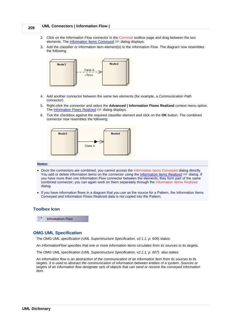
UML Connectors | Information Flow | 209
UML Dictionary
2. Click on the Information Flow connector in the Common toolbox page and drag between the twoelements. The Information Items Conveyed dialog displays.
3. Add the classifier or information item element(s) to the Information Flow. The diagram now resemblesthe following.
4. Add another connector between the same two elements (for example, a Communication Pathconnector).
5. Right-click the connector and select the Advanced | Information Flows Realized context menu option.The Information Flows Realized dialog displays.
6. Tick the checkbox against the required classifier element and click on the OK button. The combinedconnector now resembles the following:
Notes:
· Once the connectors are combined, you cannot access the Information Items Conveyed dialog directly.You add or delete information items on the connector using the Information Items Realized dialog. Ifyou have more than one Information Flow connector between the elements, they form part of the samecombined connector; you can again work on them separately through the Information Items Realizeddialog.
· If you have information flows in a diagram that you use as the source for a Pattern, the Information ItemsConveyed and Information Flows Realized data is not copied into the Pattern.
Toolbox Icon
OMG UML Specification
The OMG UML specification (UML Superstructure Specification, v2.1.1, p. 606) states:
An InformationFlow specifies that one or more information items circulates from its sources to its targets.
The OMG UML specification (UML Superstructure Specification, v2.1.1, p. 607) also states:
An information flow is an abstraction of the communication of an information item from its sources to itstargets. It is used to abstract the communication of information between entities of a system. Sources ortargets of an information flow designate sets of objects that can send or receive the conveyed informationitem.
210
210
210

UML Connectors | Information Flow | Convey Information on a Flow 210
© 1998-2010 Sparx Systems Pty Ltd
3.15.1 Convey Information on a Flow
As you create an Information Flow connector between two elements, you can specify which InformationItems or classifiers are conveyed on this flow.
To specify these Information Items or classifiers, right-click on the connection and select the Advanced |Information Item Conveyed context menu option. The Information Items Conveyed dialog displays.
Button Use to
Add Display the Select <Item> dialog, from which you select the required Informationor Classifier element(s) (see UML Modeling With Enterprise Architect - UMLModeling Tool).
Remove Remove the selected item.
Note:
If you select more than one element, they are listed in one entry for the Information Flow connector.
3.15.2 Realize an Information Flow
The Information Flows Realized dialog displays all flows that can be realized on the selected connector. To
208
163

UML Connectors | Information Flow | Realize an Information Flow211
UML Dictionary
realize an Information Flow on this connector, select the corresponding checkbox and click on the OKbutton.
If you want to change the information items conveyed on an information flow, click on the flow text and click onthe Items button. The Information Items Conveyed dialog displays, and you can add or remove items asrequired. When you click on the OK button, the Information Items Realized dialog redisplays and you canrealize the selected flow or flows as above.
3.16 Interrupt Flow
The Interrupt Flow is a connection used to define the two UML concepts of connectors for Exception Handler and Interruptible Activity Region . An Interrupt Flow is also known as an activity edge. It is typically
used in an Activity diagram .
Toolbox Icon
OMG UML Specification
The OMG UML specification (UML Superstructure Specification, v2.1.1, p. 327) states:
An activity edge is an abstract class for directed connections between two activity nodes.
3.17 Manifest
A Manifest relationship indicates that the Artifact source embodies the target model element, typically inComponent and Deployment diagrams. Stereotypes can be added to Enterprise Architect to classifythe type of manifestation of the model element (see Extending UML With Enterprise Architect).
Toolbox Icon
OMG UML Specification
The OMG UML specification (UML Superstructure Specification, v2.1.1, p. 212) states:
An artifact embodies or manifests a number of model elements. The artifact owns the manifestations, eachrepresenting the utilization of a packageable element.
Specific profiles are expected to stereotype the manifestation relationship to indicate particular forms ofmanifestation, e.g. «tool generated» and «custom code» might be two manifestations for different classes
208
210
107 121
5
151
65 62

UML Connectors | Manifest | 212
© 1998-2010 Sparx Systems Pty Ltd
embodied in an artifact.
3.18 Message
Messages indicate a flow of information or transition of control between elements. Messages can be used byTiming Diagrams , Sequence Diagrams and Communication Diagrams (but not InteractionOverview diagrams) to reflect system behavior. If between Classes or classifier instances, theassociated list of operations is available to specify the event.
Moving a Message can disrupt the organization of other features on the diagram. To avoid this, and move onlythe Message, press [Alt] while you move the Message.
Toolbox Icon
OMG UML Specification
The OMG UML specification (UML Superstructure Specification, v2.1.1, p. 491) states:
A Message defines a particular communication between Lifelines of an Interaction.
A Message is a NamedElement that defines one specific kind of communication in an Interaction. Acommunication can be, for example, raising a signal, invoking an Operation, creating or destroying anInstance. The Message specifies not only the kind of communication given by the dispatchingExecutionSpecification, but also the sender and the receiver.
A Message associates normally two OccurrenceSpecifications - one sending OccurrenceSpecification and onereceiving OccurrenceSpecification.
Note:
Communication diagrams were known as Collaboration diagrams in UML 1.4.
3.18.1 Message (Sequence Diagram)
226 212 212
52 152

UML Connectors | Message | Message (Sequence Diagram)213
UML Dictionary
Sequence diagrams depict work flow or activity over time using Messages passed from element toelement. These Messages correspond in the software model to Class operations and behavior. They aresemantically similar to the Messages passed between elements in a Communication diagram, and can be ofmany different types .
To create a Message on a Sequence diagram, follow the steps below:
1. Access the Sequence diagram. The Interaction pages of the Enterprise Architect UML Toolbox display.
2. In the Interaction Relationships page, click on the Message icon, click on the source object and dragthe cursor to the destination (target) object. The Message Properties dialog displays (if not, right-clickon the Message and select the Message Properties context menu option).
3. In the Message field, type the Message name.
39
217

UML Connectors | Message | Message (Sequence Diagram) 214
© 1998-2010 Sparx Systems Pty Ltd
Notes:
· If the Message flow is towards a Class element (dropped in from a Class diagram) or a Lifeline element having a classifier, and the destination Class has defined operations, you can click on
the drop-down arrow and select an appropriate operation name. The Message then reflects the destination Class operations.
· If the available operations are not appropriate, you can click on the Operations button and define anew operation in the target element, using the Operations dialog.
· If you create a Message without making reference to the target Class operations, no new operationis added to the target Class.
4. In the Parameters field, type any parameters that the Message has, as a comma-separated list. Ifrequired, in the Parameter Values field type the actual value for each parameter, again as a comma-separated list.
5. If the Message is a return message, in the Return Value field enter the returned value or type.
Note:
It is possible to depict returns from a Self Message . Simply create a second Self Message at theend of execution and select the Is Return checkbox in the Control Flow Type panel.
6. If the Message flow is from a Class element or Lifeline element with classifier that has defined attributes, click on the drop-down arrow in the Assign to field and select an appropriate attribute name. TheMessage reflects the attributes from the source Class. You cannot add further attributes to the sourceClass here - if no appropriate attribute is listed, open the element Properties dialog and add therequired attribute.
Otherwise, if required, type the name of the object to assign the message flow to.
7. In the Stereotype field, type or select an optional stereotype for the connector (this is displayed on thediagram, if entered).
8. If required, in the Alias field type an alias for the name of the Message.
Note:
On the diagram, the alias displays if the Use Alias if Available checkbox is selected on the Diagramtab of the Diagram Properties dialog. The Alias displays instead of or as well as the Message name,depending on the setting selected in the Alias Usage panel of the Diagram Behavior page of theOptions dialog.
9. In the Condition field, type any conditions that must be true in order for the message to be sent.
10. In the Synch: field in the Control Flow Type panel, select Synchronous or Asynchronous asappropriate.
11. In the Lifecycle field, select New to create a new element at the end of the Message, or Delete toterminate the message flow at the end of the Message. If neither case applies, leave the field at thedefault of <none>.
12. If required, in the Notes field type any explanatory notes. You can format the notes using the Rich TextNotes toolbar at the top of the field.
13. Click on the OK button to save the Message definition.
Notes:
· You can change the timing details of a message on the Timing Details dialog, and emphasize thesequence of closely-ordered messages using General Ordering .
· To toggle the numbering of messages on a Sequence diagram, select or deselect the Show SequenceNumbering checkbox on the Options dialog.
Co-Region Notation
Co-Region notation can be used as a short hand for parallel combined fragments. To access the Co-Regionsubmenu, right-click on a connector in a Sequence diagram and select the Co-Region context menu option.There are four sub-options available:
· Start at head
152
123
215
221
218
220

UML Connectors | Message | Message (Sequence Diagram)215
UML Dictionary
· End at head
· Start at tail
· End at tail.
Toolbox Icon
3.18.1.1 Self-Message
A Self-Message reflects a new process or method invoked within the calling lifeline's operation. It is aspecification of a Message , typically in a Sequence diagram .
Self-Message as Return
It is possible to depict a return from a Self Message call.
To create a Self Message return:
1. Create a second Self Message at the end of execution.
2. Double-click on the Message name to open the Message Properties dialog.
3. Select the Is Return checkbox.
4. Raise the Activation level of the return.
Self-Message Calls indicate a nested invocation; new activation levels are added with each Call.
Toolbox Icon
212 39
46
216

UML Connectors | Message | Message (Sequence Diagram) 216
© 1998-2010 Sparx Systems Pty Ltd
3.18.1.2 Call
A Call is a type of Message connector that extends the level of activation from the previous Message. AllSelf-Messages create a new activation level, but this focus of control usually ends with the next Message(unless activation levels are manually adjusted). Self-Message Calls, as depicted above by the first Call,indicate a nested invocation; new activation levels are added with each Call. Unlike a regular Messagebetween elements, a Call between elements continues the existing activation in the source element, implyingthat the Call was initiated within the previous Message's activation scope.
Toolbox Icon
212
215
45

UML Connectors | Message | Message (Sequence Diagram)217
UML Dictionary
3.18.1.3 Message Examples
The following are different types of Messages available on Sequence Diagrams . Note that Messageson Sequence diagrams can also be modified with Shape Scripts (see SDK for Enterprise Architect).
Other Sequence Messages
The following are examples of Messages that are not part of the sequence described by the diagram.
212 39

UML Connectors | Message | Message (Sequence Diagram) 218
© 1998-2010 Sparx Systems Pty Ltd
3.18.1.4 Change the Timing Details
It is possible to change the timing details of a Message in a Sequence diagram by right-clicking on theMessage connector and selecting the Timing Details context menu option. The Timing Details dialogdisplays.
Complete the fields on this dialog as follows:
Option Use to
Duration Constraint Indicate the minimum and maximum limits on how long a message can last.
39
212

UML Connectors | Message | Message (Sequence Diagram)219
UML Dictionary
Option Use to
Duration ConstraintBetween Messages
Indicate the minimum and maximum interval between sending or receipt of theprevious message at the current message's source Lifeline, and sending the currentmessage.
DurationObservation
Capture the duration of a message.
Timing Constraint Indicate the minimum and maximum time at which the message should arrive at thetarget.
Timing Observation Capture the point at which the message was sent.
See the OMG UML specification (UML Superstructure Specification, v2.1.1, p. 511).
In the diagram below, on the Open Order Message:
· Duration Constraint has been set to 0...13.
On the Get Cart Message:
· Duration Constraint Between Messages has been set to d...d*3
· Duration Observation has been set to d=duration
· Timing Constraint has been set to t...t+3
· Timing Observation has been set to t=now.
By typing a value in the Duration Constraint field, you enable the Message angle to be adjusted. Afterclicking on the OK button on the Timing Details dialog, click on the head of the Message connector and dragthe connector up or down to change the angle. You cannot extent the angle beyond the life line of theconnecting sequence object or create an angle of less than 5 degrees.
You can also create the Duration Constraint Between Messages line by dragging the General Orderingarrow up to the point at which the previous message joins the source Lifeline for the current message. A dialogdisplays on which you enter the value for the constraint. Having created the line, you can move it to any pointwithin half way along the current message and half way along the previous message, to avoid overlap withother message timing details. You can edit or delete the value either through the Timing Details dialog or byright-clicking on the line itself and selecting the appropriate context menu option.
220

UML Connectors | Message | Message (Sequence Diagram) 220
© 1998-2010 Sparx Systems Pty Ltd
3.18.1.5 General Ordering
In a Sequence diagram , the workflow is represented by the sequence of Messages down the diagram.Messages near the top of the diagram are passed before Messages lower down the diagram.
Consider the following diagram.
Message 1 is earlier than Message 2. However, in a complex diagram, or when representing finely timedoperations or parallel processing, this might not be apparent. You can reinforce the sequence using a GeneralOrdering arrow.
Click on the Message arrow. A small arrow displays at the source anchor point.
Click on this arrow and drag it to the start of the next Message in sequence (Message 2 in the example). TheGeneral Ordering arrow displays, indicating that the second Message follows the first.
The General Ordering arrow is exaggerated in the above figure. You would normally have the arrow runningalmost horizontal across the diagram.
39

UML Connectors | Message | Message (Sequence Diagram)221
UML Dictionary
You can have more than one General Ordering arrow issuing from or targeting a Message, if necessary.
3.18.1.6 Asynchronous Signal Message
You define a Message as an asynchronous signal message by displaying the Message Properties dialogand setting the Synch field to Asynchronous and the Kind field to Signal. (A synchronous message cannotbe used to convey signals, so setting the Synch field to Synchronous disables the Kind field.)
Note:
Return Value, Assign To and the Operations button, which are not applicable to asynchronous signals, aredisabled.
The Operations button changes to a Signal button, which you click on to associate the asynchronous signalmessage with a Signal element in the model. You can type the arguments corresponding to the Signalattributes into the Argument(s) field.
212

UML Connectors | Message | Message (Sequence Diagram) 222
© 1998-2010 Sparx Systems Pty Ltd
When you click on the Signal button, the Select *Signal dialog displays, through which you locate and selectthe required Signal element. (The Select *Signal dialog is a variation of the Select <Item> dialog.)

UML Connectors | Message | Message (Sequence Diagram)223
UML Dictionary
3.18.2 Message (Communication Diagram)
A Message in a Communication diagram is equivalent in meaning to a Message in a Sequence diagram. Itimplies that one object uses the services of another object, or sends a message to that object. CommunicationMessages in Enterprise Architect are always associated with an Association connector between objectinstances. Always create the Association connector first, then add a Message to the connector .
Messages can be dragged into a suitable position by clicking and dragging on the message text.
Communication Messages are ordered to reflect the sequencing of the diagram. The numbering schemeshould reflect the nesting of each event. A sequencing scheme could be:
12, 2.1, 2.2, 2.33.
This would indicate the single sequence of events 2.1, 2.2 and 2.3 occurs within an operation initiated byevent 2. This is the default pattern applied by Enterprise architect
Alternatively, the sequence could be:
12, 2.1, 2.1.1, 2.1.1.1 2.2, 2.2.1, 2.2.1.13
This would indicate that two sequences of events can be initiated by event 2, and 2.1 and 2.2 are separatesequences, not consecutive events in one sequence. You can set the sequence pattern and order using
49
199
224
224

UML Connectors | Message | Message (Communication Diagram) 224
© 1998-2010 Sparx Systems Pty Ltd
the Message Properties dialog and the Sequence Communications dialog.
If the target object is a Class or has its instance classifier set, the drop-down list of possible message namesincludes the exposed operations for the base type.
3.18.2.1 Create a Communication Message
To create a Communication Message , follow the steps below:
1. Open a diagram (one of: Communication, Analysis, Interaction Overview, Object, Activity or StateMachine).
2. Add the required objects.
3. Add an Association relationship between each pair of objects that communicate.
4. Right-click on an Association to display the context menu.
5. Select the option to add a Message from one object to the other.
6. When the Message Properties dialog displays, type in a name and any other required details.
7. Click on the OK button. The Message is added, connected to the Association and Object instances.
8. Move the Message to the required position.
3.18.2.2 Re-Order Messages
When constructing your Communication diagram, it is frequently necessary to create or delete Message'groups' and to re-order the sequence of Messages. There are two dialogs that help you perform these tasks:the Message Properties dialog and the Sequence Communications dialog.
Organize Message Groups
If you have several Messages in the form 1.1, 1.2, 1.3, 1.4, for example, but would like to start a newnumbering group on, say, the third Message (that is, 1.1, 1.2, 2.1, 2.2, 2.3 ), you can change a Message in theseries to a Start Group message.
To reorganize message groups, follow the steps below:
1. Double-click on a Message name. The Message Properties dialog displays.
223
199
212
223

UML Connectors | Message | Message (Communication Diagram)225
UML Dictionary
2. To make the selected Message the start of a new group, select the Start New Group checkbox.
3. If required, in the Notes field, type an explanatory note. You can format the text using the Rich TextNotes toolbar at the top of the field.
4. Click on the OK button to save changes.
Sequence Messages
In larger and more complex diagrams, you might have to use deeper levels of Messages in a group; forexample, 1, 1.2, 1.2.1, 1.2.1.1. You might also have to change the sequence of Messages, making Message1.3, for example, into Message 1.1.
To change the sequence or level of Messages, follow the steps below:
1. Either:
· Select the Diagram | Sequence Messages menu option
· Click on the diagram background and select the Sequence Communication Messages contextmenu option or
· Right-click on a Message and select the Sequence Communication Messages context menuoption.
The Communication Messages dialog displays.

UML Connectors | Message | Message (Communication Diagram) 226
© 1998-2010 Sparx Systems Pty Ltd
2. Click on the Message to adjust and, at the bottom of the dialog, click on the:
· 'Up Hand' or 'Down Hand' buttons to move the Message up or down the sequence (e.g. Message 1.2to Message 1.1 or 1.3)
· 'Left Hand' or 'Right Hand' buttons to move the Message up or down a level (e.g. Message 1.2.1 toMessage 1.2 or Message 1.2.1.1).
3. Repeat step 2 until the Message sequence and levels match your requirements. You might have toadjust other Message numbers (in group, sequence or level) to accommodate the changes you havemade.
4. Click on the OK button to save changes.
Note:
Communication diagrams were known as Collaboration diagrams in UML 1.4.
3.18.3 Message (Timing Diagram)

UML Connectors | Message | Message (Timing Diagram)227
UML Dictionary
Messages are the communication links between Lifelines in a Timing diagram . In the case of aTimeline, a Message is a connection between two Timeline objects.
See UML Superstructure Specification, v2.1.1, figures 14.30 and 14.31, p. 520.
Toolbox Icon
3.18.3.1 Create a Timing Message
To create a Message in a Timing diagram , at least two Lifeline objects (State or Value ) must becreated first, each with existing transition points. To create a Message between lifelines, follow the stepsbelow:
1. Click on one of the Lifelines in the Timing diagram.
2. Select the Message icon from the Timing Relationships page of the Enterprise Architect UML Toolbox (More tools | Timing).
3. Drag the cursor onto the Lifeline at the point at which the Message originates. The Timing Messagedialog displays. (If not, double-click on the Message.)
135 22
226 22 129 149

UML Connectors | Message | Message (Timing Diagram) 228
© 1998-2010 Sparx Systems Pty Ltd
The dialog consists of a set of transition points. Each transition point can be defined with the followingproperties:
Property Description
Start Defines the lifeline where the message originates.
End Defines the lifeline where the message terminates.
These are set by default when a Message is created by dragging the cursor between two Lifelines.
Property Description
Start Time Specifies the start time for a message.
End Time Specifies the end time for a message.
Name The name of the message.
Time Observation Provides information on the time of a sent message.
Duration Observation Indicates the interval of a Lifeline at a particular state, begun from amessage receipt.
Transition To The state in the target Lifeline that the Message points to.
Event The occurring event.
Time Constraint The time taken to transmit a message.
Duration Constraint Pertains to a lifeline's period at a particular state. The constraintcould be instigated by that Lifeline's receipt of a message.

UML Connectors | Message | Message (Timing Diagram)229
UML Dictionary
The following diagram shows the Message configured by the above dialog snapshot.
See UML Superstructure Specification, v2.1.1, figures 14.30 and 14.31, p. 520.
Note:
You can move the source end of the Message freely along the source timeline. However, the target end(arrow head) must attach to a transition. If you create a new Message and do not give it a target transition, itautomatically finds and attaches to the nearest transition. If you move the target end, it drags the transitionwith it.
3.19 Nesting
The Nesting Connector is an alternative graphical notation for expressing containment or nesting of elementswithin other elements. It is most appropriately used for displaying Package nesting in a Package diagram
.
Toolbox Icon
168
55

UML Connectors | Notelink | 230
© 1998-2010 Sparx Systems Pty Ltd
3.20 Notelink
A Notelink connector connects a Note to one or more other elements of any other type.
Both Note and Notelink are available in any category of the Enterprise Architect UML Toolbox, in the Commonpages. You can also select them from the UML Elements toolbar (see Using Enterprise Architect - UMLModeling Tool).
Toolbox Icon
3.21 Object Flow
Object Flows are used in Activity diagrams and State Machine diagrams . When used in an Activitydiagram, an Object Flow connects two elements, with specific data passing through it. To view sample Activitydiagrams using Object Flows, see the Object Flows in Activity Diagrams topic.
In State Machine diagrams, an Object Flow is a specification of a state flow or transition. It implies the passingof an Object instance between elements at run-time.
You can insert an Object Flow from the State or Activity pages of the Enterprise Architect UML Toolbox, orfrom the drop-down list of all relationships located in the header toolbar. You can also modify a transitionconnection to an Object Flow by selecting the ObjectFlow checkbox on the connection Properties dialog.
See the Control Flow topic for information on setting up Guards and Weights on Object Flows.
Toolbox Icon
OMG UML Specification
The OMG UML specification (UML Superstructure Specification, v2.1.1, p. 389) states:
An object flow is an activity edge that only passes object and data tokens.
126
5 9
231
165
204

UML Connectors | Object Flow | Object Flows in Activity Diagrams231
UML Dictionary
3.21.1 Object Flows in Activity Diagrams
In Activity diagrams , there are several ways to define the flow of data between objects.
The following diagram depicts a simple Object Flow between two actions, Fill Order and Ship Order, bothaccessing order information.
See UML Superstructure Specification, v2.1.1, figure 12.110, p. 391.
This explicit portrayal of the data object Order, connected to the Activities by two Object Flows, can be refinedby using the following format. Here, Action Pins are used to reflect the order.
See UML Superstructure Specification, v2.1.1, figure 12.110, p. 391.
The following diagram is an example of multiple Object Flows exchanging data between two actions.
See UML Superstructure Specification, v2.1.1, figure 12.111, p. 391.
Selection and transformation behavior, together composing a sort of query, can specify the nature of theObject Flow's data access. Selection behavior determines which objects are affected by the connection.Transformation behavior might then further specify the value of an attribute pertaining to a selected object.
Selection and transformation behaviors can be defined by attaching a note to the Object Flow. To do this,right-click on the Object Flow and select the Attach Note or Constraint context menu option. A dialog listsother flows in the diagram, to which you can select to attach the note, if the behavior applies to multiple flows.To comply with UML 2, preface the behavior with the notation «selection» or «transformation».
See UML Superstructure Specification, v2.1.1, figure 12.112, p. 392.
5
230
87

UML Connectors | Occurrence | 232
© 1998-2010 Sparx Systems Pty Ltd
3.22 Occurrence
An Occurrence relationship indicates that a Collaboration represents a classifier, in a Composite Structurediagram . An Occurrence connector is drawn from the Collaboration to the classifier.
Toolbox Icon
3.23 Package Import
A Package Import relationship is drawn from a source Package to a Package whose contents are to beimported. Private members of a target Package cannot be imported. The relationship is typically used in a Package diagram .
Toolbox Icon
OMG UML Specification
The OMG UML specification (UML Superstructure Specification, v2.1.1, p. 112) states:
A package import is a relationship between an importing namespace and a package, indicating that theimporting namespace adds the names of the members of the package to its own namespace. Conceptually, apackage import is equivalent to having an element import to each individual member of the importednamespace, unless there is already a separately-defined element import.
3.24 Package Merge
156
59
168
55

UML Connectors | Package Merge | 233
UML Dictionary
In a Package diagram , a Package Merge indicates a relationship between two Packages whereby thecontents of the target Package are merged with those of the source Package. Private contents of a targetPackage are not merged. The applicability of a Package Merge addresses any situation where multiplepackages contain identically-named elements, representing the same thing. A Package Merge merges allmatching elements across its merged Packages, along with their relationships and behaviors. Note that aPackage Merge essentially performs generalizations and redefinitions of all matching elements, but themerged Packages and their independent element representations still exist and are not affected.
The Package Merge serves a graphical purpose in Enterprise Architect, but creates an ordered Packagerelationship applied to related Packages (which can be seen under the Link tab in the Package's Propertiesdialog). Such relationships can be reflected in XMI exports or Enterprise Architect Automation Interface scriptsfor code generation or other Model Driven Architecture (MDA) interests.
Package Merge relationships are useful to reflect situations where existing architectures contain functionalitiesinvolving like elements, which are merged in a developing architecture. Merging doesn't affect the mergedobjects, and supports the common situation of product progression.
Toolbox Icon
OMG UML Specification
The OMG UML specification (UML Superstructure Specification, v2.1.1, p. 113-114) states:
A package merge is a directed relationship between two packages that indicates that the contents of the twopackages are to be combined. It is very similar to Generalization in the sense that the source elementconceptually adds the characteristics of the target element to its own characteristics resulting in an elementthat combines the characteristics of both.
This mechanism should be used when elements defined in different packages have the same name and areintended to represent the same concept. Most often it is used to provide different definitions of a given conceptfor different purposes, starting from a common base definition. A given base concept is extended inincrements, with each increment defined in a separate merged package. By selecting which increments tomerge, it is possible to obtain a custom definition of a concept for a specific end. Package merge is particularlyuseful in meta-modeling and is extensively used in the definition of the UML metamodel.
Conceptually, a package merge can be viewed as an operation that takes the contents of two packages andproduces a new package that combines the contents of the packages involved in the merge. In terms of modelsemantics, there is no difference between a model with explicit package merges, and a model in which all themerges have been performed.
3.25 Realize
A source object implements or Realizes its destination object. Realize connectors are used in a Use Case ,Component or Requirements diagram to express traceability and completeness in the model. Abusiness process or Requirement is realized by one or more Use Cases , which in turn are realized by
55 168
7
65 71
189 146

UML Connectors | Realize | 234
© 1998-2010 Sparx Systems Pty Ltd
some Classes , which in turn are realized by a Component , and so on. Mapping Requirements, Classesand such across the design of your system, up through the levels of modeling abstraction, ensures the bigpicture of your system remembers and reflects all the little pictures and details that constrain and define it.(See UML Model Management.)
Toolbox Icon
(and )
OMG UML Specification
The OMG UML specification (UML Superstructure Specification, v2.1.1, p. 131) states:
A Realization signifies that the client set of elements are an implementation of the supplier set, which servesas the specification. The meaning of 'implementation' is not strictly defined, but rather implies a more refinedor elaborate form in respect to a certain modeling context. It is possible to specify a mapping between thespecification and implementation elements, although it is not necessarily computable.
3.26 Recursion
A Recursion is a type of Message used in Sequence diagrams to indicate a recursive function.
Toolbox Icon
3.27 Role Binding
Role Binding is the mapping between a Collaboration Occurrence's internal roles and the respective Parts required to implement a specific situation, typically in a Composite Structure diagram . The associated
Parts can have properties defined to enable the binding to occur, and the Collaboration to take place.
A Role Binding connector is drawn between a Collaboration and the classifier's fulfilling roles, with theCollaboration's internal binding roles labeled on the classifier end of the connector.
152 158
212 39
157
168 59
156

UML Connectors | Role Binding | 235
UML Dictionary
Toolbox Icon
OMG UML Specification
The OMG UML specification (UML Superstructure Specification, v2.1.1, p. 174) states:
A mapping between features of the collaboration type and features of the classifier or operation. This mappingindicates which connectable element of the classifier or operation plays which role(s) in the collaboration. Aconnectable element may be bound to multiple roles in the same collaboration occurrence (that is, it may playmultiple roles).
3.28 Represents
The Represents connector indicates that a Collaboration is used in a classifier, typically in a CompositeStructure diagram . The connector is drawn from the Collaboration to its owning classifier.
Toolbox Icon
3.29 Representation
The Representation relationship is a specialization of a Dependency , connecting Information Itemelements that represent the same idea across models, typically in an Analysis diagram . For example,Bonus and Salary are both a representation of the Information Item Wage.
156
59
205 163
67

UML Connectors | Representation | 236
© 1998-2010 Sparx Systems Pty Ltd
Toolbox Icon
3.30 Trace
The Trace relationship is a specialization of a Dependency , connecting model elements or sets ofelements that represent the same concept across models. Traces are often used to track requirements andmodel changes, typically in a Traceability diagram (see UML Model Management), or in a Class , Use Case
, Object or Composite Structure diagram.
As changes can occur in both directions, the order of this Dependency is usually ignored. The relationship'sproperties can specify the trace mapping, but the trace is usually bi-directional, informal and rarelycomputable.
Toolbox Icon
3.31 Transition
A Transition defines the logical movement from one State to another, in a State Machine diagram . TheTransition can be controlled through the following connector Properties dialog:
205
56
7 58 59
129 9

UML Connectors | Transition | 237
UML Dictionary
Option Use to
Guard Type in an expression that is evaluated after an Event is dispatched, but before thecorresponding Transition is triggered. If the guard is true at that time, the Transitionis enabled; otherwise, it is disabled.
Effect is a Behavior Convert the Effect field from a free-text field to the definition of a specific Activity orbehavior.
Enterprise Architect displays the Select <Item> dialog to prompt you to select theActivity or behavior element from the model (see UML Modeling With EnterpriseArchitect - UML Modeling Tool).
Effect Either:
· Type a description of the effect of the Transition, or
· If you have selected the Effect is a Behavior check box, select an Activity orbehavior to be performed during the Transition (to change this subsequently,click on the [ ... ] button to redisplay the Select <Item> dialog).
Trigger
Name Specify the name of the trigger.
Type Specify the type of trigger: Call, Change, Signal or Time.
· Call - specifies that the event is a CallEvent, which sends a message to theassociated object by invoking an operation.
· Change - specifies that the event is a ChangeEvent, which indicates that thetransition is the result of a change in value of an attribute.
· Signal - specifies that the event is a SignalEvent, which corresponds to the

UML Connectors | Transition | 238
© 1998-2010 Sparx Systems Pty Ltd
Option Use to
receipt of an asynchronous signal instance.
· Time - corresponds to a TimeEvent; which specifies a moment in time.
Note:
Code generation for State Machines currently supports Change and Time triggerevents only, and expects a specification value.
Specification Specify the event instigating the Transition.
Save Save the current trigger.
Add Select triggers from the model using the Select Trigger dialog.
Note:
To add multiple triggers, press [Ctrl] while selecting each trigger.
Delete Remove the selected trigger from the list.
Triggers List the current triggers for the Transition.
Note:
Fork and Join segments can have neither triggers nor guards.
Toolbox Icon
OMG UML Specification
The OMG UML specification (UML Superstructure Specification, v2.1.1, p. 568) states:
A transition is a directed relationship between a source vertex and a target vertex. It may be part of acompound transition, which takes the state machine from one state configuration to another, representing thecomplete response of the state machine to an occurrence of an event of a particular type.
3.32 Use
A Use relationship indicates that one element requires another to perform some interaction. The Use (orUsage) relationship does not specify how the target supplier is used, other than that the source client uses it indefinition or implementation. A Use relationship is a sub-typed Dependency relationship.
You typically use the Use relationship in Use Case diagrams to model how Actors use systemfunctionality (Use Cases ), or to illustrate usage dependencies between Classes or Components .
205
7 94
146 152 158

UML Connectors | Use | 239
UML Dictionary
Notes:
· It is more usual (and correct UML) to have an Association Connector between an Actor and a UseCase.
· To depict a usage dependency on a Class or Component diagram, draw a Dependency connector.Right-click on the Dependency, and select the Dependency Stereotypes | Use context menu option.
Toolbox Icon
OMG UML Specification
The OMG UML specification (UML Superstructure Specification, v2.1.1, p. 138) states:
A usage is a relationship in which one element requires another element (or set of elements) for its fullimplementation or operation. In the metamodel, a Usage is a Dependency in which the client requires thepresence of the supplier.
199
56 65

Index 240
© 1998-2010 Sparx Systems Pty Ltd
Index- A -Abstract
Complex Models 163
AcceptEvent Action
Triggers Tab 81
Action
AcceptEvent, Triggers Tab 81
BroadcastSignal, Signal Tab 81
Element 79
Expansion Node 86
Local Pre/Post Conditions 89
Notation 81
Operations 79
SendSignal, Signal Tab 81
StructuralFeature 81
Trigger, AcceptEvent 81
Type, Set 81
Update Operation 79
Action Pin
Add To Action 87
As Action Property 88
As Argument For Call Action 87
Assign To Action 88
Properties 87
Activation
End 45
Extend Down 45
Extend Up 45
Lower 45
Raise 45
Sequence Element 45
Suppress 45
Activation Layer
Sequence Diagram Lifelines 46
Activation Levels
Sequence Diagram Lifeline Self Messages 46
Active
Classes 153
State Configuration 130
Activity
Element 90
Instance 236
Notation 91
Parameter Nodes 91
Partition 93, 126
Process Element 189
Region Element 128
Structured 138
Structured, Conditional Node 136, 139
Structured, Loop Node 136, 139
Structured, Sequential 136
Activity Diagram
Description 5
Elements And Connectors 5
Example 5
Object Flows 231
Operations 79
Activity Edge
Connector 211
Relationship 211
Activity Final
Element 110
Activity Partition
Docking 126
Element 126
Horizontal 126
Vertical 126
Actor
Element 94
Add
Expansion Region 110
Instance Variable 166
Interruptible Activity Region 122
Port To Element 170
Property Value to Part 169
Aggregate
Connector 198
Relationship 198
Aggregation Connector
Change Form 199
Analysis
Stereotypes 179
Analysis Diagram
Description 67
Diagram 67
Elements And Connectors 67
Example 67
Apply
Stereotype To Dependency Relationship 206
Artifact
Element 151
Assembly
Connector 199
Relationship 199
Associate
Connector 199
Relationship 199

Index241
UML Dictionary
Association
Class 187
Connector 199
N-Ary 187
Relationship 199
Association Class
Connector 200
Link New Class To Association 201
Relationship 200
Association End
Qualifiers 173, 175
Asynchronous Signal Message
Associate With Signal 221
Connector 221
Relationship 221
Attribute
Qualifiers 175
- B -Behavior
Instance 236
Behavioral Diagram
Elements 78
Overview 4
Boundary
Element 179
Element Settings 144
Element, Create 180
Object Settings 144
Properties 144
BroadcastSignal Action
Signal Tab 81
Business Interaction Diagram
Description 75
Elements And Connectors 75
Example 75
Business Modeling Diagram
Description 75
Elements And Connectors 75
Example 75
Business Process Modeling 67
- C -Call
Self Message 216
Call Action
Pin As Argument 87
Central Buffer Node
Element 95
Change
Form Of Aggregation Connector 199
Choice
Element 95
Class
Active Classes 153
Element 152
Make Into Association Class 201
Parameterized Classes (Templates) 154
Class Diagram
Description 56
Elements And Connectors 56
Example 56
Classifier
Behavior 118
Item Conveyed 210
Properties 61
Collaboration
Element 156
Message 224
Collaboration Diagram
Description 49
Elements And Connectors 49
Example 49
Message Colors 51
Collaboration Occurrence
Element 157
Combined Fragment
Create 98
Element 96
Interaction Operator 99
Communication
Connector 203
Message 223
Message, Create 224
Message, Level 224
Message, Properties 224
Message, Sequence 224
Relationship 203
Communication Diagram
Description 49
Elements And Connectors 49
Example 49
Labelled Associations 49
Message Colors 51
Numbering In 49
Communication Path
Connector 202
Relationship 202
Component
Description 65

Index 242
© 1998-2010 Sparx Systems Pty Ltd
Component
Diagram 65
Element 158
Elements And Connectors 65
Example 65
Compose
Connector 202
Relationship 202
Composite
Elements 180
State 129, 130
State Regions 12
Composite Aggregation
Connector 202
Relationship 202
Composite Structure Diagram
Description 59
Elements And Connectors 59
Example 59
Compress
Timeline 36
Transition 36
Concurrent Substate
Regions 12
Conditional Node
Structured Activity 136, 139
Configure Timeline Dialog
States Tab 29
Transitions Tab 31
Connector
Activity Edge 211
Aggregate 198
Assembly 199
Associate 199
Association 199
Association Class 200
Asynchronous Signal Message 221
Communication 203
Communication Path 202
Compose 202
Composite Aggregation 202
Connector 203
Control Flow 204
Delegate 205
Dependency 205
Dependency, Apply Stereotype 206
Deployment 206
Extend 207
Generalization 207
Generalize 207
Implements 233
Include 208
Information Flow 208
Inheritance 207
Interrupt Flow 211
Manifest 211
Message 212
Nesting 229
Notelink 230
Object Flow 230
Occurrence 232
Overview 196
Package Import 232
Package Merge 232
Pkg Import 232
Pkg Merge 232
Realize 233
Recursion 234
Relationship 203
Representation 235
Represents 235
Role Binding 234
Self-Message 215
Trace 236
Transition 236
Usage 238
Use 238
What Is A? 196
Constraint
Note, Element 126
Post Condition On Actions 89
Precondition On Actions 89
Continuation
Element 132
Control
Create 182
Element 181
Control Flow
Connector 204
Guard 204
Relationship 204
Weight 204
Convey
Information Item 210
Co-Region Notation 212
Create
Boundary Element 180
Combined Fragment 98
Communication Messages 224
Control Element 182
Entity 183
Timing Diagram 23

Index243
UML Dictionary
Create
Timing Message 227
CSV
Export State Machine Table To 21
Custom
Diagram 71, 72, 73
Custom Diagram
Description 69
Elements And Connectors 69
Example 69
Model 69
- D -Data Type
Element 159
Instance 159
Referenced 159
Database Schema
Description 75
Diagram 75
Elements And Connectors 75
Example 75
Datastore
Element, Activity Diagram 102
Decision
Element 102
Define
Run-Time Variable 166
Delegate
Connector 205
Relationship 205
Delete
Instance Variable 167
Dependency
Connector 205
Relationship 205
Relationship, Apply Stereotype 206
Deployment
Connector 206
Diagram 62
Relationship 206
Deployment Diagram
Description 62
Elements And Connectors 62
Example 62
Deployment Spec
Element 160
Device
Element 161
Diagram
Activity, Description 5
Analysis 67
Behavioral, Overview 4
Business Interaction 75
Business Modeling 75
Class 56
Collaboration 49
Communication 49
Component 65
Composite Structure 59
Custom 69, 71, 72, 73
Database Schema 75
Deployment 62
Diagram 179, 181, 182
Extended 4
Extended UML 67
Frame 104
Frame (Border) 104
Hyperlink 104
Interaction 22, 39, 49, 52
Interaction Overview 52
Logical 56
Maintenance 72
MDG Technology 4
Move, Impact On Element 102, 110, 111, 117
Object 58
Overview 4
Package 55
Reference 104
Requirements 71
Robustness 39, 49, 67, 179, 181, 182
Schema Diagram 75
Sequence 39
State 9
State Machine 9
Structural, Overview 54
Timing 22
Types 4
UML 4
Use Case 7
User Interface 73
User Interface Design 69
What Is A? 4
Diagram Frame 104
Diagram Gate
Element 105
Dialog
New Action 81
Qualifiers 175
Set Attribute 85
Set Feature 85

Index 244
© 1998-2010 Sparx Systems Pty Ltd
Dialog
Set Operation 85
Document Artifact
Element 161
Duration
Constraint 218
Constraint Between Messages 218
Observation 218
- E -Element
Action 79
Activity 90
Activity Final 110
Activity Partition 126
Activity Region 128
Actor 94
Artifact 151
Behavioral Diagram 78
Boundary 179
Boundary, Settings 144
Central Buffer Node 95
Choice 95
Class 152
Collaboration 156
Collaboration Occurrence 157
Combined Fragment 96
Component 158
Composite 180
Constraint Note 126
Continuation 132
Continutaion 132
Control 181, 182
Data Type 159
Datastore, Activity Diagram 102
Decision 102
Deployment Spec 160
Device 161
Diagram Frame 104
Diagram Gate 105
Document Artifact 161
Endpoint 106
Entity 182
Entry Point 107
Enumeration 162
Event 183
Exception 107
Execution Environment 162
Exit Point 110
Expansion Region 107
Expose Interface 163
Extended By Stereotype 178
Feature 184
Flow Final 111
Fork 112, 114
Fragment 96
History 116
Hyperlink 184
Information Item 163
Initial 117
Instance 165
Interaction 118
Interaction Occurrence 119
InteractionUse 119
Interface 164
Interruptible Activity Region 121
Join 112, 115
Junction 122
Lifeline 123
Merge 102
Merge Node 124
N-Ary Association 187
Node 165
Note (Constraint, Comment) 126
Object 165
Occurrence 119
Package 168
Packaging Component 188
Part 168
Partition 126
Port 169
Primitive 173
Process 189
Properties, Edit From Package 55
Pseudo-State 13
Receive 127
Receive Event 183
Region 128
Region, Expansion 107
Region, Interruptible Activity 121
Requirement 189
Screen 190
Send 129
Send Event 183
Sequence Diagram 43
Sequence, Lifecycle 41
Signal 178
State 129
State Invariant 132, 134
State Lifeline 135
State Machine 136

Index245
UML Dictionary
Element
State/Continuation 132
Structural Diagram 150
Structured Activity, Conditional Node 136, 139
Structured Activity, Loop Node 136, 139
Structured Activity, Sequential Node 136, 138
Structured Activity, Structured Node 136, 138
Sub-Activity 90
Sub-Activity, Conditional Node 136, 139
Sub-Activity, Loop Node 136, 139
Sub-Activity, Sequential Node 136, 138
Sub-Activity, Structured Node 136, 138
Submachine State 129, 136
Synch 142
System Boundary 142
Table 192
Terminate 144
Test Case 191
Trigger 145
UI Control 192
UML 78
Use Case 146
User Interface 192
Value Lifeline 149
Endpoint
Element 106
Enterprise Architect
Alignment With UML 2
Connectors 196
Entity
Create 183
Element 182
Entry Point
Element 107
Enumeration
Element 162
Literal 162
Eriksson-Penker Business Extensions 67
Event
Element 183
Receive 183
Send 183
Exception
Element 107
Execution Environment
Element 162
Exit Point
Element 110
Expansion Node
Action 86
Expansion Region
Add 110
Element 107
Export
State Machine Table To CSV 21
Expose Interface
Element 163
Extend
Connector 207
Relationship 207
Extended Elements 178
Extended UML Diagrams 67
Extension Points
Use Case 147
Extension Stereotypes 178
- F -FDD Methodology 184
Feature
Element 184
Feature Driven Design Methodology 184
File
Hyperlink To 184
Flow Final
Element 111
Fork
Element 112, 114
Pseudo-State 112, 114
Fork/Join
Element 112
Fragment
Element 96
- G -General Ordering
Sequence Diagram Messages 220
Generalize
Connector 207
Relationship 207
- H -Help
Topic, Hyperlink To 184
History
Element 116
Hyperlink
As Sub Activities 184
Diagrams 184

Index 246
© 1998-2010 Sparx Systems Pty Ltd
Hyperlink
Element 184
To External Files 184
To Help Topics 184
To Internet Facilities 184
To Matrix Profiles 184
To Model Search 184
To Team Review 184
- I -Implements
Connector 233
Relationship 233
Inbuilt Stereotypes 178
Include
Connector 208
Relationship 208
Information Flow
And Patterns 208
Connector 208
In Combination 208
Realized 210
Relationship 208
Information Item
Conveyed 210
Element 163
Inheritance
Connector 207
Relationship 207
Inherited Port
Manage 170
Initial
Element 117
Inline Sequence Elements
Part And Port 49
Insert
Boundary Element 144
Instantiated Template 154
Interaction
Diagram 22, 49, 52
Element 118
Interaction Diagram
Description 39
Diagram 39
Elements And Connectors 39
Example 39
Interaction Occurrence
Element 119
Interaction Operator
Combined Fragment 99
Interaction Overview Diagram
Description 52
Elements And Connectors 52
Example 52
InteractionUse
Element 119
Interface
Element 164
Expose Element 163
Provided 163
Required 163
Internet Facilities
Hyperlink To 184
Interrupt Flow
Connector 211
Relationship 211
Interruptible Activity Region
Add 122
Element 121
Interval Bar
Context Menu 32
Timing Diagram Time Interval 32
Introduction
To UML Objects 78
- J -Join
Element 112, 115
Pseudo-State 112, 115
Junction
Element 122
- L -Label Visibility
On Sequence Messages 48
Layout
Sequence Diagram 42
Legend
Add To State Machine Table 20
Remove From State Machine Table 20
Lifecycle
Of A Sequence Element 41
Lifeline
Element 123
Objects In Sequence Diagrams 44
Sequence Element, Termination 41
Local
Pre/Post Conditions 89
Logical Diagram

Index247
UML Dictionary
Logical Diagram
Class Diagram 56
Loop Node
Structured Activity 136, 139
- M -Maintenance Diagram
Description 72
Elements And Connectors 72
Example 72
Manage
Inherited Ports 170
Redefined Ports 170
Manifest
Connector 211
Relationship 211
Matrix Profile
Hyperlink To 184
Merge
Element 102, 124
Node 124
Merge Packages
Relationship 232
Message
Asynchronous Signal 221
Collaboration 224
Colors In Communication Diagrams 51
Communication 223
Communication, Create 224
Connector 212
Create On Timing Diagram 227
Endpoint 124
Group, Start New 224
Label 125
Level 224
Move 212
Recursion 234
Relationship 212
Self Message 215
Self Message Call 216
Sequence Communication 224
Sequence Diagram, Asyncronous Signal 221
Sequence Diagram, Examples 217
Sequence Diagram, General Ordering 220
Sequence Diagram, Self Message 215
Sequence, Create 212
Sequence, Label Visibility 48
Sequencing 224
Timing Diagram 226
Message Angle
Adjust With Duration Constraint 218
Methodology
FDD 184
Feature-Driven Design 184
Model Search
Hyperlink To 184
Model-View-Controller Pattern 182
MVC Pattern 182
- N -N-Ary
Association Element 187
Nesting
Connector 229
Relationship 229
New Action Dialog 81
New Structured Activity Dialog 136
Node
Element 165
Notation
Co-Region 212
Note
Element 126
Notelink
Connector 230
Relationship 230
Numeric Range Generator
Timeline Element States 29
- O -Object
Element 165
Instance 165
State, Set 167
Object Diagram
Description 58
Elements And Connectors 58
Example 58
Object Flow
Connector 230
In Activity Diagram 231
In State Machine Diagram 230
Multiple 231
Relationship 230
Selection Behavior 231
Simple 231
Transformation Behavior 231
With Action Pins 231
Occurrence

Index 248
© 1998-2010 Sparx Systems Pty Ltd
Occurrence
Connector 232
Element 119
Relationship 232
Operation
As Action 79
- P -Package
Element 168
Package Diagram
Description 55
Elements And Connectors 55
Example 55
Package Import
Connector 232
Relationship 232
Package Merge
Connector 232
Relationship 232
Packaging Component
Element 188
Parameterized Classes (Templates) 154
Part
Add Property Value 169
Element 168
Property Tab 172
Qualifiers 175
Represent On Sequence Diagram 49
Partition
Activity 126
Docking 126
Element 126
Horizontal 126
Vertical 126
Pattern
Model-View-Controller 182
MVC 182
Pin
Action 87
Add To Action 87
As Action Property 88
As Argument For Call Action 87
Assign To Action 87, 88
Properties 87
Pkg Import
Connection 232
Relationship 232
Pkg Merge
Connector 232
Relationship 232
Port
Add To Element 170
Element 169
For Trigger Element 145
Inherited 170
Property Tab 172
Qualifiers 175
Redefined 170
Represent On Sequence Diagram 49
Pre/Post Conditions
Constraints 89
Local 89
Notes 89
On Actions 89
Primitive
Element 173
Process
Element 189
Properties
Effect Tab 79
Element, Trigger Tab 145
Of Classifiers, Composite Structure Diagram 61
Properties,
Part, Property Tab 172
Port, Property Tab 172
Property Value
Part, Add To 169
Pseudo-State
Elements 13
Fork 112, 114
In State Machine Diagram 13
Join 112, 115
- Q -Qualified Association 173
Qualifier
Association End 175
Association Property 173
Attribute 175
Attribute Property 173
Dialog 175
Part 175
Part Property 173
Port 175
Port Property 173
Set Properties 175

Index249
UML Dictionary
- R -Realize
An Information Flow 210
Connector 233
Relationship 233
Receive
Element 127
Event 183
Reception
Definition 178
Of Signal 178
Rectangle Notation
For Use Cases 148
Recursion
Connector 234
Message 234
Relationship 234
Redefined Port
Manage 170
Region
Composite State 12
Concurrent Substate 12
Element 128
Expansion, Element 107
Interruptible Activity, Element 121
On Composite State 130
State Machine 12
Relationship
Activity Edge 211
Aggregate 198
Assembly 199
Associate 199
Association 199
Association Class 200
Asynchronous Signal 221
Communication 203
Communication Path 202
Compose 202
Composite Aggregation 202
Connector 203
Control Flow 204
Delegate 205
Dependency 205
Dependency, Apply Stereotype 206
Deployment 206
Extend 207
Generalization 207
Generalize 207
Implements 233
Include 208
Information Flow 208
Inheritance 207
Interrupt Flow 211
Manifest 211
Message 212
Nesting 229
Notelink 230
Object Flow 230
Occurrence 232
Package Import 232
Package Merge 232
Pkg Import 232
Pkg Merge 232
Realize 233
Recursion 234
Representation 235
Represents 235
Role Binding 234
Self Message 215
Trace 236
Transition 236
Usage 238
Use 238
Re-Order
Messages 224
Representation
Connector 235
Relationship 235
Represents
Connector 235
Relationship 235
Requirement
Element 189
Hide Stereotype Letter 189
Show Stereotype Letter 189
Requirements Diagram
Description 71
Elements And Connectors 71
Example 71
Robustness Diagram 179
Role Binding
Connector 234
Relationship 234
Run State 166
Add Instance Variable 166
Run-Time
Variable, Define 166
Run-Time State
Add Instance Variable 166
Delete Instance Variable 167

Index 250
© 1998-2010 Sparx Systems Pty Ltd
Run-Time State
Introduction 166
- S -Scenario
Use Case 43
Schema
Database 75
Screen
Element 190
Self Message
Calls 216
Self-Message
Connector 215
Hierarchy, Sequence Diagram 46
Relationship 215
Return 215
Send
Element 129
Event 183
SendSignal Action
Signal Tab 81
Sequence
Communication Messages 224
Message, Change Timing Details 218
Message, Create 212
Message, Timing Details 218
Sequence Diagram
Activation Levels 46
And Version Control 44
Damage To 44
Description 39
Element Activation 45
Elements 43
Elements And Connectors 39
Example 39
Layout 42
Lifeline Activation Level 46
Messages, Asynchronous Signal 221
Messages, Self Message 215
Self-Message Hierarchy 46
Top Margin, Change 48
Sequence Diagram Message
Examples 217
External To Sequence 217
General Ordering 220
Sequence Element
Inline, Part And Port 49
Sequence Message
Label Visibility 48
Modify Height 42
Sequential Node
Structured Activity 136, 138
Set
Object State 167
Set Attribute Dialog 85
Set Feature Dialog 85
Set Operation Dialog 85
Signal
Element 178
Reception 178
State
Add To State Lifeline Element 25
Chart 9
Composite 129, 130
Delete On State Lifeline Element 25
Diagram 9
Edit On State Lifeline Element 25
Element 129
Entry And Exit Actions 129
In Timeline Element 29
Locate In State Machine Diagram 20
Locate In State Machine Table 20
Reposition In State Machine Table 20
Simple 129
State Machine Table Conventions 21
State Invariant
Element 132, 134
State Lifeline
Element 135
State Lifeline Element
Add State 25
Add To Timing Diagram 24
Add Transition 26
Change Transition Time 26
Define Name 24
Delete State 25
Delete Transition 26
Edit State 25
Edit Transition 26
Merge Transitions 26
Move Transition 26
Set Timeline Start Position 24
Sizing and Scale 24
Synchronize Transition 26
State Machine
Element 136
Regions 12
State Machine Diagram
Description 9
Display Format 9

Index251
UML Dictionary
State Machine Diagram
Elements And Connectors 9
Example 9
Locate State In State Machine Table 20
Locate Transition In State Machine Table 20
Locate Trigger In State Machine Table 20
State Machine Table
Add States 18
Add Substates 18
Add Triggers 19
Cell Color 15
Cell Enumeration 15
Cell Highlights 15
Cell Size 15
Change Position In Diagram View 18
Change Size 18
ChangeTransitions 19
Conventions 21
Description 14
Export To CSV 21
Format 14
Insert Transitions 19
Legend, Add 20
Legend, Remove 20
Locate State In State Machine Diagram 20
Locate Transition In State Machine Diagram 20
Locate Trigger In State Machine Diagram 20
Operations, Overview 17
Options 15
Remove Substate Parent Relation 18
Reposition States 20
Reposition Substates 20
Reposition Triggers 20
State-Next State 14
State-Trigger 14
Table Format 15
Trigger-State 14
State Region
Composite 12
State/Continuation
Element 132
Stereotype
Analysis 179
Apply To Dependency Relationship 206
Extension 178
Inbuilt 178
Stereotyped Element
Table 192
Structural Diagram
Elements 150
Structural Diagrams
Overview 54
StructuralFeature Action
Set Structural Feature 81
Structured Activity
Conditional Node 136, 139
Element 136, 138, 139
Loop Node 136, 139
Nested 136
Node 136, 138
Sequential Node 136, 138
Structured Activity Node 138
Sub-Activity
Conditional Node 136, 139
Element 90, 136, 138
Loop Node 136, 139
Submachine State
Element 129, 136
Substate
Reposition In State Machine Table 20
Sub-State 130
Synch
Element 142
System Boundary
Element 142
- T -Table
Detail 192
Element 192
Properties 192
State Machine 14
Team Review
Hyperlink To 184
Template
Instantiated 154
Parameterized Classes 154
Terminate
Element 144
Test Case
Element 191
Time Event 127
Time Interval
Compress 32, 36
Context Menu 32
Copy and Paste 36
Create 32
Delete 32
Description 32
Move 32
Operations 36

Index 252
© 1998-2010 Sparx Systems Pty Ltd
Time Interval
Resize 32
Select 32
Shift Left Or Right 36
Transitions 36
Time Range
Set For Timing Diagram 23
Timeline Element States
Add Via Configure Timeline Dialog 29
Delete via Configure Timeline Dialog 29
Edit Via Configure Timeline Dialog 29
Maintain 29
Numeric Range Generator 29
Timeline Range
Set For Timing Diagram 23
Timeline Start Position
Set For State Lifeline Element 24
Timing
Constraint 218
Details, Change 218
Message 226
Message, Create 227
Observation 218
Timing Diagram
Add Value Lifeline Element 27
Create 23
Description 22
Edit Options 24
Edit Value Lifeline Element 27
Elements And Connectors 22
Example 22
Set Time Range 23
Top Margin
Sequence Diagram, Change 48
Trace
Connector 236
Relationship 236
Traceability
In Requirements Models 71
Transition
Add To State Lifeline Elements 26
Add Via Configure Timeline Dialog 31
Change In State Machine Table 19
Change Time, State Lifeline Element 26
Connector 236
Delete On State Lifeline Element 26
Delete Via Configure Timeline Dialog 31
Edit In Time Intervals 36
Edit On State Lifeline Elements 26
Edit Via Configure Timeline Dialog 31
Effect 236
Guard 236
Highlight Associated Trigger or State 19
Insert In State Machine Table 19
Locate In State Machine Diagram 20
Locate In State Machine Table 20
Merge On State Lifeline Element 26
Move On State Lifeline Elements 26
Properties 236
Relationship 236
State Machine Table Conventions 21
Trigger 236
Trigger
Create 145
Create In State Machine Table 19
Create In Transition Properties 236
Element 145
For Transition 236
Locate In State Machine Diagram 20
Locate In State Machine Table 20
Ports 145
Properties Tab 145
Reposition In State Machine Table 20
State Machine Table Conventions 21
Type 236
- U -UI Control
Element 192
UML
Connectors 196
Definition 2
Dictionary 2
Elements 78
Extend 2
Recommended Reading 2
UML Behavioral Diagram
Overview 4
UML Diagram
Extended 4, 67
MDG Technology 4
Overview 4
Types 4
What Is A? 4
UML Element
Behavioral Diagram Elements 78
Structural Diagram Elements 150
UML Structural Diagram
Overview 54
UML Toolbox
Business Modeling Group 75

Index253
UML Dictionary
Unified Modeling Language 2
Usage
Connector 238
Relationship 238
Use
Connector 238
Relationship 238
Use Case
Element 146
Extension Points 147
Rectangle Notation 148
Scenarios 43
Use Case Diagram
Description 7
Elements And Connectors 7
Example 7
User Interface
Control Element 192
Element 192
Screen Prototype 190
User Interface Design 69
User Interface Diagram
Description 73
Elements And Connectors 73
Example 73
- V -Value Lifeline Element 149
Add States 28
Add To Timing Diagram 27
Add Transitions 28
Change Transition Time 28
Delete Transitions 28
Edit Transitions 28
Sizing and Scale 27
States 27
Transitions 27
Version Control
And Sequence Diagram 44
- W -Web
Page Modeling 194
Stereotypes 194
Web Page
Prototype 190
What Is
A Connector? 196

UML Dictionarywww.sparxsystems.com