Enrolling the Keypad WT5500 Installation Instructions Sensors... · If more than one LCD keypad is...
2
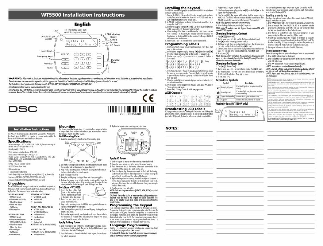
English WARNING: Please refer to the System Installation Manual for information on limitations regarding product use and function, and information on the limitations as to liability of the manufacturer. These instructions are to be used in conjunction with the appropriate Control Panel Installation Manual, with which this equipment is intended to be used. This Installation Sheet applies to the following models: WT5500-433 / WT5500-868 / WT5500P-433 / WT5500P-868. Operating Instructions shall be made available to the user. Do not dispose the waste battery as unsorted municipal waste. Consult your local rules and /or laws regarding recycling of this battery, it will help protect the environment by reducing the number of batteries consumed. Some of the materials that are found within the battery could become toxic if not disposed properly and/or may affect the environment, and indirectly everybody’s health. WT5500 Installation Instructions 1 2 3 4 5 6 7 8 0 # 9 * System is Ready to Arm <> Function Keys LED Indicators Ready Armed Trouble AC Power Scroll Keys Ambient Light Sensor LCD Emergency Keys Fire Auxiliary Panic < > indicates user can scroll through options DG009033 29007335R001 Enrolling the Keypad The WT5500 must be configured in tandem with the PC9155 in order for the system to function as desired. 1. Turn on the PC9155. The panel will be alert to any keypad enrollment activity for a period of two minutes. Note that the PC9155 Ready and AC LEDs will be flashing for this two-minute period. 2. A WT5500 must be turned on during this two-minute period for it to be assigned to the PC9155. 3. Simultaneously press and hold [4] and [1]; by doing so you force the key- pad to broadcast its ESN (Electronic Serial Number). 4. When the keypad has been successfully enrolled - this should take less than 5 seconds - on the system, the message ‘Enrollment Successful’ will be displayed on the keypad LCD for five seconds. The Ready and AC LEDs will return to their previous state. 5. Repeat steps 3 and 4 on each additional keypad to be enrolled. Programming Labels 1. Use this section to assign a meaningful name (e.g. Front Door, Hall- way, etc.) to each zone. 2. Enter keypad programming by pressing [4][8][Installer Code][4]. Enter the 3-digit section number for the label to be programmed. 3. Use the arrow keys (<>) to move the cursor underneath the letter to be changed. 4. Press the number keys 1 through 9, corresponding to the letter you require. For example, pressing number key 2 once will display the letter D; pressing it again will display the letter E; pressing it a third time will display the let- ter F, and so on. 5. When the required letter or number is displayed use the arrow keys (<>) to scroll to the next letter. 6. When you are finished programming the Zone Label, press [4]. Scroll to ‘Save’ and press [4] again. 7. Repeat Steps 2 through 5 until all Labels are programmed. ASCII Characters Broadcasting LCD Labels LCD programming is done using the keypad. If more than one LCD keypad is present on the system, labels programmed at one keypad can be broadcast to all other LCD keypads. Perform the following in order to broadcast labels: 1. Program one LCD keypad completely. 2. Enter keypad programming by pressing [4][8][Installer Code][4] at the keypad that was programmed. 3. Enter Section [998]. The keypad will broadcast the label programming to the PC9155. The PC9155 will then broadcast the label information to other WT5500 keypads that have been enrolled by way of 2-way wireless. NOTE: This operation may take several minutes. 4. When the keypad is finished press the [#] key to exit. NOTE: Label broadcast from this keypad is only compatible with other WT5500 keypads. Changing Brightness/Contrast 1. Press [4][6] [Master Code]. 2. Use the arrow keys (<>) to scroll to Brightness or Contrast Control. 3. Press [4] to select the setting you want to adjust. 4. Brightness Control: There are multiple backlight levels. Use the arrow keys (<>) to scroll to the desired level. Press [4] to select. 5. Contrast Control: There are four different display contrast levels. Use the arrow keys (<>) to scroll to the desired contrast level. Press [4] to select. 6. To exit, press [#]. NOTE: During battery operation, the keypad uses the ambient light sensor to automatically adjust the backlighting brightness lev- els in order to conserve battery life. Changing the Buzzer Level 1. Press [4][6] [Master Code]. 2. Use the arrow keys (<>) to scroll to Buzzer Control. Press [4] to select. 3. Use the arrow keys (<>) to scroll to the desired buzzer level among the 21 available selections. Press [4] to select. 4. To exit, press [#]. Keypad LED Symbols Proximity Tags (WT5500P only) You can use the proximity tag to perform any keypad function that would normally require a user access code. Simply present the tag to the target icon or to the left of the Keypad LCD. Enrolling proximity tags Enrolling a tag with one keypad will enroll it automatically to all WT5500P keypads enrolled on the system. 1. Enter [4][5][Master Code]. You will enter the User Code Edit Select menu. 2. Enter a two-digit User Code slot (01-16, 40) to be associated with the proximity tag. Alternatively, scroll to the two-digit user number and press the [4] key. You will enter the New Code Edit menu. 3. Enter the four- or six-digit New Code. The LCD will prompt you to swipe your proximity tag. Otherwise, press the [#] key to exit. 4. Present your proximity tag to the keypad. If enrollment is successful, acknowledgement beeps will sound and the keypad LCD will read ‘Tag Enrolled Successfully’. If the proximity tag has been enrolled previously, an error tone will sound. The LCD will read ‘Duplicate Tag/User Code’. 5. The keypad will return to the User Code Edit Select menu. Deleting proximity tags Delete the prox tags from the system when they are lost or no longer needed. 1. Enter [4][5] [Master Code] on the keypad. 2. Enter or select the User Code slot you wish to delete. You will enter the User Code Edit Select menu. 3. Press [4] to delete both the user code and the proximity tag. NOTE: User code can only be deleted individually. NOTE: User 40 - Master Code cannot be deleted; a deletion attempt on this user code will delete the proximity tag only. NOTE: A user code, once deleted, must be re-enrolled before it can be used again. [1] - A, B, C, 1 [4] - J, K, L, 4 [7] - S, T, U, 7 [0] - Space [2] - D, E, F, 2 [5] - M, N, O, 5 [8] - V, W, X, 8 [3] - G, H, I, 3 [6] - P, Q, R, 6 [9] - Y, Z, 9,0 Symbol Description Ready Light (green) If the Ready light is on, the system is ready for arming. Armed Light (red) If the Armed light is on, the system has been armed successfully. System Trouble (yellow) Indicates that a system trouble is active. AC (green) Indicates that AC is present at the keypad. The complete R&TTE Declaration of Conformity can be found at http://www.dsc.com/listings_index.aspx. The WT5500 Wire-Free Keypad is designed to work with the PC9155 Wire- less Panel. Since the PC9155 is mounted in a secure location within the home, the WT5500 is the main interface to the system. Specifications Unpacking The WT5500 keypad package is available in five distinct configurations, Wall mount, Wall mount w/Proximity, Desk Stand, Accessory Kit and Proxim- ity Tags Only. The contents of each are described below. Mounting You should mount the keypad where it is accessible from designated points of entry and exit. Once you have selected a dry and secure location, perform the following steps to mount the keypad. Wall Mounting Plate 1. Locate the screw holes (4) at each corner of the mounting plate. 2. Use the four screws provided to affix the mounting plate to the wall, ensure the mounting tabs are facing you (see above diagram). 3. Align the four mounting slots in the WT5500 housing with the four mount- ing tabs protruding from the mounting plate. 4. Slide the keypad into place. 5. Firmly but carefully snap the keypad down onto the mounting plate. 6. To fasten the keypad more securely onto the mounting plate, locate the two screw holes in the bottom of the mounting plate then using the two screws provided in the hardware pack, screw the keypad into place. Desk Stand - WT5500D 1. Insert the four rubber feet (found in the hardware pack) into the indentations provided in the bottom of the desk stand. 2. Place the desk stand on a secure, uncluttered surface. 3. Align the four mounting slots in the WT5500 housing with the four mount- ing tabs protruding from the desk stand. 4. Slide the keypad into place. Firmly but carefully snap the keypad down onto the desk stand. 5. To fasten the keypad securely onto the desk stand, locate the two holes in the top corners of the back of the desk stand, then using the two screws provided screw the keypad to the desk stand. Apply Battery Power 1. Slide the keypad up and out from the mounting plate/desk stand (remov- ing the screws first if required). The bay for the four AA batteries is open and visible at the back of the keypad. 2. Insert the batteries as directed on the back of the keypad. Ensure the cor- rect polarity is observed. 3. Replace the keypad on the mounting plate / desk stand. Apply AC Power 1. Slide the keypad up and out from the mounting plate / desk stand. 2. Locate the power adaptor jack at the back of the keypad housing. 3. Place the adaptor plug in the housing indentation, perpendicular to the keypad. Insert the adaptor plug firmly into the jack. 4. Pivot the adaptor plug downwards so that it fits flush with the housing. Guide the AC wire along the channel provided in the keypad housing; the wire will finally extend through the bottom of the housing. 5. Replace the keypad on the mounting plate/desk stand (in the latter case, a further channel is provided in the bottom of the desk stand. Guide the AC wire along this channel; the wire will finally extend through an opening in the back of the stand). 6. Plug the adaptor into a wall outlet. NOTE: Only use the power adaptor (4.5VDC, 0.5A, 2.25W) supplied with the kit. CAUTION: The socket-outlet in which the direct plug-in adaptor is inserted, must be close to the keypad and easily accessible. The plug of the adaptor serves as a means of disconnection from the supply mains. Programming the Keypad There are several programming options available for the keypad (see below). Programming the keypad is similar to programming the rest of the system. To turn an option on/off, press the number corresponding to the option on the number pad. The numbers of the options that are currently turned on will be displayed along the top of the LCD. For information on programming the rest of your security system, please refer to your system’s Installation Manual. A maximum of four keypads can be on the system at any one time. Language Programming Hold the (<>) keys for 2 seconds to enter language programming. Scroll to the desired language and press [4] to select. If Section 075, Option 4 is turned off, language programming can only be performed while in installers programming. Installation Instructions Temperature range: -10°C to +55°C (14°F to 131°F), Temperature range for UL/ULC: 0°C to +49°C (32°F to 120°F) Humidity (MAX): 93%R.H. Plastic enclosure protection degree: IP30, IK04 Power Adaptor Output Voltage: 4.5VDC @ 0.5A Models - US/Latin America: SA103A-0506-6U; Canada: SA103A-0506-6; EU: SA103A-0506G-6; UK: SA106C-05BS; AUS./NZ: SA106C-05AS; China: SA106C-05HS. Battery: 4 AA, 3V, Energizer Alkaline WT5500 Current draw: 50mA Wall-mount tamper 5 programmable function keys Ready (Green LED), Armed (Red LED), Trouble (Yellow LED), AC (Green LED) Frequency: 433.92MHz (WT5500-433/WT5500P-433 only) Frequency: 868.35MHz (WT5500-868/WT5500P-868 only) WT5500 - WALL MOUNT WT5500DMK - ACCESSORY KIT • 1 WT5500 Keypad • 1 WT5500DMK Keypad • 1 WT5500BRK Wall Bracket • 1 Hardware Pack • 1 Installation Manual • 1 Power Adaptor • 1 Inner Door Sticker • 4 AA Batteries WT5500P - WALL MOUNT/PROX TAG • 1 Hardware Pack • 1 WT5500P Keypad • 1 WT5500BRK Wall Bracket WT5500D - DESK STAND • 1 Installation Manual • 1 WT5500 Keypad • 1 Inner Door Sticker • 1 WT5500DMK Desk Stand • 4 AA Batteries • 1 WT5500BRK Wall Bracket • 1 Hardware Pack • 1 Installation Manual • 1 PT4 or PT8 Prox Tag (433MHz/868MHz) • 1 Inner Door Sticker • 1 Power Adaptor PROXIMITY TAGS ONLY • 4 AA Batteries • 1 PT4 or PT8 Prox Tag (433MHz/868MHz) • 2 Hardware Packs • 1 Installation Manual Mounting Tabs DG009049 Screw Holes Screw Holes Screw Holes Screw Holes DG009096 DG009048 Mounting Holes Mounting Holes Batteries Plug Wire Channel Tamper Switch NOTES: System is Ready to Arm <> DG009153 Prox Tag Reader
-
Upload
hoangthien -
Category
Documents
-
view
216 -
download
2
Transcript of Enrolling the Keypad WT5500 Installation Instructions Sensors... · If more than one LCD keypad is...
English
WARNING: Please refer to the System Installation Manual for information on limitations regarding product use and function, and information on the limitations as to liability of the manufacturer.These instructions are to be used in conjunction with the appropriate Control Panel Installation Manual, with which this equipment is intended to be used.This Installation Sheet applies to the following models: WT5500-433 / WT5500-868 / WT5500P-433 / WT5500P-868.Operating Instructions shall be made available to the user.Do not dispose the waste battery as unsorted municipal waste. Consult your local rules and /or laws regarding recycling of this battery, it will help protect the environment by reducing the number of batteriesconsumed. Some of the materials that are found within the battery could become toxic if not disposed properly and/or may affect the environment, and indirectly everybody’s health.
WT5500 Installation Instructions
1 2 3
4 5 6
7 8
0 #
9
*
System isReady to Arm <>
FunctionKeys
LED IndicatorsReadyArmedTroubleAC Power
Scroll Keys
Ambient LightSensor
LCD
Emergency Keys
Fire
Auxiliary
Panic
< > indicates user canscroll through options
DG
0090
33
29007335R001
Enrolling the KeypadThe WT5500 must be configured in tandem with the PC9155 in order for thesystem to function as desired.1. Turn on the PC9155. The panel will be alert to any keypad enrollment
activity for a period of two minutes. Note that the PC9155 Ready and ACLEDs will be flashing for this two-minute period.
2. A WT5500 must be turned on during this two-minute period for it to beassigned to the PC9155.
3. Simultaneously press and hold [ ] and [1]; by doing so you force the key-pad to broadcast its ESN (Electronic Serial Number).
4. When the keypad has been successfully enrolled - this should take lessthan 5 seconds - on the system, the message ‘Enrollment Successful’ willbe displayed on the keypad LCD for five seconds. The Ready and AC LEDswill return to their previous state.
5. Repeat steps 3 and 4 on each additional keypad to be enrolled.
Programming Labels 1. Use this section to assign a meaningful name (e.g. Front Door, Hall-
way, etc.) to each zone.2. Enter keypad programming by pressing [ ][8][Installer Code][ ].
Enter the 3-digit section number for the label to be programmed.3. Use the arrow keys (<>) to move the cursor underneath the letter to
be changed.
4. Press the number keys 1 through 9, corresponding to the letter you require.For example, pressing number key 2 once will display the letter D; pressingit again will display the letter E; pressing it a third time will display the let-ter F, and so on.
5. When the required letter or number is displayed use the arrow keys (<>)to scroll to the next letter.
6. When you are finished programming the Zone Label, press [ ]. Scroll to‘Save’ and press [ ] again.
7. Repeat Steps 2 through 5 until all Labels are programmed.
ASCII Characters
Broadcasting LCD LabelsLCD programming is done using the keypad. If more than one LCD keypad ispresent on the system, labels programmed at one keypad can be broadcastto all other LCD keypads. Perform the following in order to broadcast labels:
1. Program one LCD keypad completely.2. Enter keypad programming by pressing [ ][8][Installer Code][ ] at the
keypad that was programmed. 3. Enter Section [998]. The keypad will broadcast the label programming to
the PC9155. The PC9155 will then broadcast the label information to otherWT5500 keypads that have been enrolled by way of 2-way wireless.
NOTE: This operation may take several minutes.4. When the keypad is finished press the [#] key to exit.NOTE: Label broadcast from this keypad is only compatible withother WT5500 keypads.Changing Brightness/Contrast1. Press [ ][6] [Master Code].2. Use the arrow keys (<>) to scroll to Brightness or Contrast Control.3. Press [ ] to select the setting you want to adjust.4. Brightness Control: There are multiple backlight levels. Use the arrow keys
(<>) to scroll to the desired level. Press [ ] to select.5. Contrast Control: There are four different display contrast levels. Use the arrow
keys (<>) to scroll to the desired contrast level. Press [ ] to select.6. To exit, press [#].NOTE: During battery operation, the keypad uses the ambient lightsensor to automatically adjust the backlighting brightness lev-els in order to conserve battery life.Changing the Buzzer Level1. Press [ ][6] [Master Code].2. Use the arrow keys (<>) to scroll to Buzzer Control. Press [ ] to select.3. Use the arrow keys (<>) to scroll to the desired buzzer level among
the 21 available selections. Press [ ] to select.4. To exit, press [#].
Keypad LED Symbols
Proximity Tags (WT5500P only)
You can use the proximity tag to perform any keypad function that would normally require a user access code. Simply present the tag to the target icon or to the left of the Keypad LCD.Enrolling proximity tagsEnrolling a tag with one keypad will enroll it automatically to all WT5500P keypads enrolled on the system.1. Enter [ ][5][Master Code]. You will enter the User Code Edit Select menu.2. Enter a two-digit User Code slot (01-16, 40) to be associated with the
proximity tag. Alternatively, scroll to the two-digit user number and pressthe [ ] key. You will enter the New Code Edit menu.
3. Enter the four- or six-digit New Code. The LCD will prompt you to swipeyour proximity tag. Otherwise, press the [#] key to exit.
4. Present your proximity tag to the keypad. If enrollment is successful,acknowledgement beeps will sound and the keypad LCD will read ‘TagEnrolled Successfully’. If the proximity tag has been enrolled previously, anerror tone will sound. The LCD will read ‘Duplicate Tag/User Code’.
5. The keypad will return to the User Code Edit Select menu.Deleting proximity tagsDelete the prox tags from the system when they are lost or no longer needed.1. Enter [ ][5] [Master Code] on the keypad. 2. Enter or select the User Code slot you wish to delete. You will enter the User
Code Edit Select menu.3. Press [ ] to delete both the user code and the proximity tag.NOTE: User code can only be deleted individually. NOTE: User 40 - Master Code cannot be deleted; a deletion attempton this user code will delete the proximity tag only.NOTE: A user code, once deleted, must be re-enrolled before it canbe used again.
[1] - A, B, C, 1 [4] - J, K, L, 4 [7] - S, T, U, 7 [0] - Space[2] - D, E, F, 2 [5] - M, N, O, 5 [8] - V, W, X, 8[3] - G, H, I, 3 [6] - P, Q, R, 6 [9] - Y, Z, 9,0
Symbol Description
Ready Light (green) If the Ready light is on, the system is ready for arming.
Armed Light (red) If the Armed light is on, the system has been armed successfully.
System Trouble (yellow) Indicates that a system trouble is active.AC (green) Indicates that AC is present at the keypad.
The complete R&TTE Declaration of Conformity can be found at http://www.dsc.com/listings_index.aspx.
The WT5500 Wire-Free Keypad is designed to work with the PC9155 Wire-less Panel. Since the PC9155 is mounted in a secure location within thehome, the WT5500 is the main interface to the system.Specifications
UnpackingThe WT5500 keypad package is available in five distinct configurations,Wall mount, Wall mount w/Proximity, Desk Stand, Accessory Kit and Proxim-ity Tags Only. The contents of each are described below.
MountingYou should mount the keypad where it is accessible from designated pointsof entry and exit. Once you have selected a dry and secure location, performthe following steps to mount the keypad.Wall Mounting Plate1. Locate the screw holes (4) at each corner of the mounting plate.
2. Use the four screws provided to affix the mounting plate to the wall, ensurethe mounting tabs are facing you (see above diagram).
3. Align the four mounting slots in the WT5500 housing with the four mount-ing tabs protruding from the mounting plate.
4. Slide the keypad into place.5. Firmly but carefully snap the keypad down onto the mounting plate.6. To fasten the keypad more securely onto the mounting plate, locate the
two screw holes in the bottom of the mounting plate then using the twoscrews provided in the hardware pack, screw the keypad into place.
Desk Stand - WT5500D1. Insert the four rubber feet
(found in the hardware pack)into the indentations providedin the bottom of the desk stand.
2. Place the desk stand on asecure, uncluttered surface.
3. Align the four mounting slots in the WT5500 housing with the four mount-ing tabs protruding from the desk stand.
4. Slide the keypad into place. Firmly but carefully snap the keypad downonto the desk stand.
5. To fasten the keypad securely onto the desk stand, locate the two holes inthe top corners of the back of the desk stand, then using the two screwsprovided screw the keypad to the desk stand.
Apply Battery Power1. Slide the keypad up and out from the mounting plate/desk stand (remov-
ing the screws first if required). The bay for the four AA batteries is openand visible at the back of the keypad.
2. Insert the batteries as directed on the back of the keypad. Ensure the cor-rect polarity is observed.
3. Replace the keypad on the mounting plate / desk stand.
Apply AC Power 1. Slide the keypad up and out from the mounting plate / desk stand.2. Locate the power adaptor jack at the back of the keypad housing.3. Place the adaptor plug in the housing indentation, perpendicular to the
keypad. Insert the adaptor plug firmly into the jack.4. Pivot the adaptor plug downwards so that it fits flush with the housing.
Guide the AC wire along the channel provided in the keypad housing; thewire will finally extend through the bottom of the housing.
5. Replace the keypad on the mounting plate/desk stand (in the latter case, afurther channel is provided in the bottom of the desk stand. Guide the ACwire along this channel; the wire will finally extend through an opening inthe back of the stand).
6. Plug the adaptor into a wall outlet.NOTE: Only use the power adaptor (4.5VDC, 0.5A, 2.25W) suppliedwith the kit.CAUTION: The socket-outlet in which the direct plug-in adaptor isinserted, must be close to the keypad and easily accessible. Theplug of the adaptor serves as a means of disconnection from thesupply mains.Programming the KeypadThere are several programming options available for the keypad (see below).Programming the keypad is similar to programming the rest of the system. Toturn an option on/off, press the number corresponding to the option on thenumber pad. The numbers of the options that are currently turned on will bedisplayed along the top of the LCD. For information on programming the restof your security system, please refer to your system’s Installation Manual. Amaximum of four keypads can be on the system at any one time.
Language Programming Hold the (<>) keys for 2 seconds to enter language programming. Scrollto the desired language and press [ ] to select.If Section 075, Option 4 is turned off, language programming can only be performed while in installers programming.
Installation Instructions
Temperature range: -10°C to +55°C (14°F to 131°F), Temperature range for UL/ULC: 0°C to +49°C (32°F to 120°F)Humidity (MAX): 93%R.H.Plastic enclosure protection degree: IP30, IK04Power Adaptor Output Voltage: 4.5VDC @ 0.5A Models - US/Latin America: SA103A-0506-6U; Canada: SA103A-0506-6; EU: SA103A-0506G-6; UK: SA106C-05BS; AUS./NZ: SA106C-05AS; China: SA106C-05HS.Battery: 4 AA, 3V, Energizer AlkalineWT5500 Current draw: 50mA Wall-mount tamper5 programmable function keysReady (Green LED), Armed (Red LED), Trouble (Yellow LED), AC (Green LED)Frequency: 433.92MHz (WT5500-433/WT5500P-433 only)Frequency: 868.35MHz (WT5500-868/WT5500P-868 only)
WT5500 - WALL MOUNT WT5500DMK - ACCESSORY KIT• 1 WT5500 Keypad • 1 WT5500DMK Keypad• 1 WT5500BRK Wall Bracket • 1 Hardware Pack• 1 Installation Manual • 1 Power Adaptor• 1 Inner Door Sticker• 4 AA Batteries WT5500P - WALL MOUNT/PROX TAG • 1 Hardware Pack • 1 WT5500P Keypad
• 1 WT5500BRK Wall BracketWT5500D - DESK STAND • 1 Installation Manual• 1 WT5500 Keypad • 1 Inner Door Sticker• 1 WT5500DMK Desk Stand • 4 AA Batteries• 1 WT5500BRK Wall Bracket • 1 Hardware Pack• 1 Installation Manual • 1 PT4 or PT8 Prox Tag (433MHz/868MHz)• 1 Inner Door Sticker• 1 Power Adaptor PROXIMITY TAGS ONLY• 4 AA Batteries • 1 PT4 or PT8 Prox Tag (433MHz/868MHz)• 2 Hardware Packs • 1 Installation Manual
MountingTabs
DG
0090
49
ScrewHoles
ScrewHoles
ScrewHoles
ScrewHoles
DG009096
DG
0090
48
MountingHoles
MountingHoles
BatteriesPlug
WireChannel
TamperSwitch
NOTES:
System isReady to Arm <>
DG009153
Prox Tag Reader

Keypad Function Key ProgrammingEnter keypad programming by pressing [ ][8][Installer Code][ ][000]. Press 1 through 5 for individual function key programming. [1]-[5] Function Key Assignment
Keypad Function KeysPlease see your system installation manual for more details on the function key options below.
Keypad ProgrammingEnter keypad programming by pressing [ ][8][Installer Code][ ][001]-[034] Zone Label 1 to 34 (Default: ‘Zone _01’ - ‘Zone _34’)E.g. For Zone 1 enter section 001, for Zone 2 enter section 002, etc.
[065] Fire Alarm Label (28 Characters) Default: ’Fire_Zone’
[066] Fail to Arm Event Message Default: ‘System_Has_Failed_to_Arm’
[067] Alarm When Armed Event Message Default: ‘Alarm_Occurred_While_Armed_ < >’
[068] Command Output 1 LabelDefault: ‘Command_0/P_1’
[069] Command Output 2 LabelDefault: ‘Command_O/P_2’
[074] First Keypad Options
Function Key Button Valid Range Default Function
[1] Function Key 1 00 - 33 03 Stay Arm I_______I_______I
[2] Function Key 2 00 - 33 04 Away Arm I_______I_______I
[3] Function Key 3 00 - 33 06 Chime On/Off I_______I_______I
[4] Function Key 4 00 - 33 08 Bypass I_______I_______I
[5] Function Key 5 00 - 33 16 Quick Exit I_______I_______I
[00] - Null [06] - Chime On/Off [15] - For Future Use[01] - For Future Use [07] - For Future Use [16] - Quick Exit[02] - For Future Use [08] - Bypass Mode [17] - Activate Stay/Away Zones[03] - Stay Arm [09] - [12] - For Future Use [25] - Instant Stay Arm[04] - Away Arm [13] - Command Output 1 [33] - Night Arm[05] - No Entry Arm [14] - Command Output 2
Section Zone Label
[001] to [034] 1-34I_____I_____I_____I_____I_____I_____I_____I_____I_____I_____I_____I_____I_____I_____I
I_____I_____I_____I_____I_____I_____I_____I_____I_____I_____I_____I_____I_____I_____I
[065]I_____I_____I_____I_____I_____I_____I_____I_____I_____I_____I_____I_____I_____I_____I
I_____I_____I_____I_____I_____I_____I_____I_____I_____I_____I_____I_____I_____I_____I
[066]I_____I_____I_____I_____I_____I_____I_____I_____I_____I_____I_____I_____I_____I_____I
I_____I_____I_____I_____I_____I_____I_____I_____I_____I_____I_____I_____I_____I_____I
[067]I_____I_____I_____I_____I_____I_____I_____I_____I_____I_____I_____I_____I_____I_____I
I_____I_____I_____I_____I_____I_____I_____I_____I_____I_____I_____I_____I_____I_____I
[068]I_____I_____I_____I_____I_____I_____I_____I_____I_____I_____I_____I_____I_____I_____I
I_____I_____I_____I_____I_____I_____I_____I_____I_____I_____I_____I_____I_____I_____I
[069]I_____I_____I_____I_____I_____I_____I_____I_____I_____I_____I_____I_____I_____I_____I
I_____I_____I_____I_____I_____I_____I_____I_____I_____I_____I_____I_____I_____I_____I
Default Opt. ON OFF
ON I_____I 1 Fire Key Enabled Fire Key Disabled
ON I_____I 2 Auxiliary Key Enabled Auxiliary Key Disabled
ON I_____I 3 Panic Key Enabled Panic Key Disabled
OFF I_____I 4 Quick Arm Prompt ON Quick Arm Prompt OFF
OFF I_____I 5 Quick Exit Prompt ON Quick Exit Prompt OFF
OFF I_____I 6 Bypass Options Prompt ON Bypass Options Prompt OFF
OFF I_____I 7 User Initiated Call-up Prompt ON User Initiated Call-up Prompt OFF
OFF I_____I 8 Hold Key [P] Prompt ON Hold Key [P] Prompt OFF
[075] Second Keypad Options
[076] Third Keypad Options
[077] LCD Message
[078] Download LCD Message Duration Default: 003 I_____I_____I_____I (Valid entries are 000-255), 000=Unlimited Message DisplayThis number represents the number of times the downloaded message is cleared by pressing any key after the message has timed out.
[100] CO Detector Alarm LabelDefault: ‘CO_Alarm_Evacuate_Area’Section/Label
[101] System Label Default: ‘System’Section/Label
[120] Partition 1 Command Output #1 Default: ‘Command_O/P_1’Section/Label
[121] Partition 1 Command Output #2 Default: ‘Command_O/P_2’Section/Label
[996] Reset Programmable Labels to Factory Defaults [997] View Software Version[998] Global Label Broadcast [999] Reset Keypad Programming to Factory Defaults
Default Opt. ON OFFON I_____I 1 Local Clock Display ON Local Clock Display OFFOFF I_____I 2 Local Clock Displays 24-hr Time Local Clock Displays AM/PMOFF I_____I 3 Auto Alarm Scroll ON Auto Alarm Scroll OFF
OFF I_____I 4 Language Selection Available From Any Menu
Language Selection Available in Installer’s
ON I_____I 5 Power LED Enabled Power LED DisabledON I_____I 6 Power LED Indicates AC Present ON Power LED Indicates AC Present OFFOFF I_____I 7 Alarms Displayed While Armed Alarms Not Displayed While Armed OFF I_____I 8 Auto-Scroll Open Zones ON Auto-Scroll Open Zones OFF
Default Option ON OFFOFF I____I 1 For Future Use For Future UseOFF I____I 2 For Future Use For Future UseOFF I____I 3 For Future Use For Future UseOFF I____I 4 For Future Use For Future UseOFF I____I 5 Late to Open Prompts Late to Open PromptsON I____I 6 Power Save Mode ON Power Save Mode OFFOFF I____I 7 For Future Use For Future UseOFF I____I 8 For Future Use For Future Use
[077]I_____I_____I_____I_____I_____I_____I_____I_____I_____I_____I_____I_____I_____I_____I_____I_____|
I_____I_____I_____I_____I_____I_____I_____I_____I_____I_____I_____I_____I_____I_____I_____I_____|
[100] I_____I_____I_____I_____I_____I_____I_____I_____I_____I_____I_____I_____I_____I______|______|_____|
I_____I_____I_____I_____I_____I_____I_____I_____I_____I_____I_____I_____I_____I______|______|_____|
[101]I_____I_____I_____I_____I_____I_____I_____I_____I_____I_____I_____I_____I_____I______|
I_____I_____I_____I_____I_____I_____I_____I_____I_____I_____I_____I_____I_____I______|
[120]I_____I_____I_____I_____I_____I_____I_____I_____I_____I_____I_____I_____I_____I______|
I_____I_____I_____I_____I_____I_____I_____I_____I_____I_____I_____I_____I_____I______|
[121]I_____I_____I_____I_____I_____I_____I_____I_____I_____I_____I_____I_____I_____I______|
I_____I_____I_____I_____I_____I_____I_____I_____I_____I_____I_____I_____I_____I______|
NOTES: Limited Warranty Digital Security Controls (DSC) warrants that for a period of 12 months from thedate of purchase, the product shall be free of defects in materials and workman-ship under normal use and that in fulfilment of any breach of such warranty, DSCshall, at its option, repair or replace the defective equipment upon return of theequipment to its repair depot. This warranty applies only to defects in parts andworkmanship and not to damage incurred in shipping or handling, or damage dueto causes beyond the control of DSC such as lightning, excessive voltage,mechanical shock, water damage, or damage arising out of abuse, alteration orimproper application of the equipment. The foregoing warranty shall apply only tothe original buyer, and is and shall be in lieu of any and all other warranties,whether expressed or implied and of all other obligations or liabilities on the partof DSC. DSC neither assumes responsibility for, nor authorizes any other personpurporting to act on its behalf to modify or to change this warranty, nor to assumefor it any other warranty or liability concerning this product. In no event shall DSCbe liable for any direct, indirect or consequential damages, loss of anticipatedprofits, loss of time or any other losses incurred by the buyer in connection withthe purchase, installation or operation or failure of this product. Warning: DSC recommends that the entire system be completely tested on a regu-lar basis. However, despite frequent testing, and due to, but not limited to, criminaltampering or electrical disruption, it is possible for this product to fail to perform asexpected. Important Information: Changes or modifications not expresslyapproved by DSC could void the user’s authority to operate this equipment.FCC Compliance StatementCaution: Changes or modifications not expressly approved by Digital SecurityControls could void your authority to use this equipment.This equipment generates and uses radio frequency energy and if not installedand used properly, in strict accordance with the manufacturer’s instructions,may cause interference to radio and television reception. It has been type testedand found to comply with the limits for Class B device in accordance with thespecifications in Subpart “B” of Part 15 of FCC Rules, which are designed toprovide reasonable protection against such interference in any residential instal-lation. However, there is no guarantee that interference will not occur in a partic-ular installation. If this equipment does cause interference to television or radioreception, which can be determined by turning the equipment off and on, theuser is encouraged to try to correct the interference by one or more of the fol-lowing measures: (i) Re-orient the receiving antenna; (ii) increase the separa-tion between the equipment and receiver; (iii) connect the equipment into anoutlet on a circuit different from that to which the receiver is connected. If nec-essary, the user should consult the dealer or an experienced radio/televisiontechnician for additional suggestions. The user may find the following bookletprepared by the FCC helpful: “How to Identify and Resolve Radio/TelevisionInterference Problems”. This booklet is available from the U.S. GovernmentPrinting Office, Washington, D.C. 20402, Stock # 004-000-00345-4.This Class B digital apparatus complies with Canadian ICES-003.Cet appareil numérique de la classe B est conforme à la norme NMB-003 duCanada. IC:160A-WT5500: The term IC before the radio certification numbersignifies that the Industry Canada technical specifications were met.
IMPORTANT INFORMATION: Changes/modifications not expressly approved byDSC could void the user’s authority to operate this equipment.IMPORTANT - READ CAREFULLY: DSC Software purchased with or withoutProducts and Components is copyrighted and is purchased under the followinglicense terms:• This End-User License Agreement (“EULA”) is a legal agreement between You(the company, individual or entity who acquired the Software and any related Hard-ware) and Digital Security Controls, a division of Tyco Safety Products Canada Ltd.(“DSC”), the manufacturer of the integrated security systems and the developer ofthe software and any related products or components (“HARDWARE”) which Youacquired.
• If the DSC software product (“SOFTWARE PRODUCT” or “SOFTWARE”) isintended to be accompanied by HARDWARE, and is NOT accompanied by newHARDWARE, You may not use, copy or install the SOFTWARE PRODUCT. TheSOFTWARE PRODUCT includes computer software, and may include associatedmedia, printed materials, and “online” or electronic documentation. • Any software provided along with the SOFTWARE PRODUCT that is associatedwith a separate end-user license agreement is licensed to You under the terms ofthat license agreement. • By installing, copying, downloading, storing, accessing or otherwise using theSOFTWARE PRODUCT, You agree unconditionally to be bound by the terms of thisEULA, even if this EULA is deemed to be a modification of any previous arrange-ment or contract. If You do not agree to the terms of this EULA, DSC is unwilling tolicense the SOFTWARE PRODUCT to You, and You have no right to use it.SOFTWARE PRODUCT LICENSEThe SOFTWARE PRODUCT is protected by copyright laws and internationalcopyright treaties, as well as other intellectual property laws and treaties. TheSOFTWARE PRODUCT is licensed, not sold. 1. GRANT OF LICENSE This EULA grants You the following rights:(a) Software Installation and Use - For each license You acquire, You may haveonly one copy of the SOFTWARE PRODUCT installed. (b) Storage/Network Use - The SOFTWARE PRODUCT may not be installed,accessed, displayed, run, shared or used concurrently on or from differentcomputers, including a workstation, terminal or other digital electronic device(“Device”). In other words, if You have several workstations, You will have toacquire a license for each workstation where the SOFTWARE will be used.(c) Backup Copy - You may make back-up copies of the SOFTWARE PRODUCT,but You may only have one copy per license installed at any given time. You mayuse the back-up copy solely for archival purposes. Except as expressly provided inthis EULA, You may not otherwise make copies of the SOFTWARE PRODUCT,including the printed materials accompanying the SOFTWARE.2. DESCRIPTION OF OTHER RIGHTS AND LIMITATIONS (a) Limitations on Reverse Engineering, Decompilation and Disassembly - Youmay not reverse engineer, decompile, or disassemble the SOFTWARE PRODUCT,except and only to the extent that such activity is expressly permitted by applicablelaw notwithstanding this limitation. You may not make any changes ormodifications to the Software, without the written permission of an officer of DSC.You may not remove any proprietary notices, marks or labels from the SoftwareProduct. You shall institute reasonable measures to ensure compliance with theterms and conditions of this EULA.(b) Separation of Components - The SOFTWARE PRODUCT is licensed as asingle product. Its component parts may not be separated for use on more than oneHARDWARE unit.(c) Single INTEGRATED PRODUCT - If You acquired this SOFTWARE withHARDWARE, then the SOFTWARE PRODUCT is licensed with the HARDWARE as asingle integrated product. In this case, the SOFTWARE PRODUCT may only beused with the HARDWARE as set forth in this EULA..(d) Rental - You may not rent, lease or lend the SOFTWARE PRODUCT. You maynot make it available to others or post it on a server or web site.(e) Software Product Transfer - You may transfer all of Your rights under thisEULA only as part of a permanent sale or transfer of the HARDWARE, provided Youretain no copies, You transfer all of the SOFTWARE PRODUCT (including allcomponent parts, the media and printed materials, any upgrades and this EULA),and provided the recipient agrees to the terms of this EULA. If the SOFTWAREPRODUCT is an upgrade, any transfer must also include all prior versions of theSOFTWARE PRODUCT.(f) Termination - Without prejudice to any other rights, DSC may terminate thisEULA if You fail to comply with the terms and conditions of this EULA. In suchevent, You must destroy all copies of the SOFTWARE PRODUCT and all of itscomponent parts.(g) Trademarks - This EULA does not grant You any rights in connection with anytrademarks or service marks of DSC or its suppliers.3. COPYRIGHT - All title and intellectual property rights in and to the SOFTWAREPRODUCT (including but not limited to any images, photographs, and text
incorporated into the SOFTWARE PRODUCT), the accompanying printed materials,and any copies of the SOFTWARE PRODUCT, are owned by DSC or its suppliers.You may not copy the printed materials accompanying the SOFTWARE PRODUCT.All title and intellectual property rights in and to the content which may beaccessed through use of the SOFTWARE PRODUCT are the property of therespective content owner and may be protected by applicable copyright or otherintellectual property laws and treaties. This EULA grants You no rights to use suchcontent. All rights not expressly granted under this EULA are reserved by DSC andits suppliers.4. EXPORT RESTRICTIONS - You agree that You will not export or re-export theSOFTWARE PRODUCT to any country, person, or entity subject to Canadian exportrestrictions. 5. CHOICE OF LAW - This Software License Agreement is governed by the laws ofthe Province of Ontario, Canada.6. ARBITRATION - All disputes arising in connection with this Agreement shall bedetermined by final and binding arbitration in accordance with the Arbitration Act,and the parties agree to be bound by the arbitrator’s decision. The place ofarbitration shall be Toronto, Canada, and the language of the arbitration shall beEnglish.7. LIMITED WARRANTY(a) NO WARRANTY - DSC PROVIDES THE SOFTWARE “AS IS” WITHOUTWARRANTY. DSC DOES NOT WARRANT THAT THE SOFTWARE WILL MEET YOURREQUIREMENTS OR THAT OPERATION OF THE SOFTWARE WILL BEUNINTERRUPTED OR ERROR-FREE.(b) CHANGES IN OPERATING ENVIRONMENT - DSC shall not be responsible forproblems caused by changes in the operating characteristics of the HARDWARE, orfor problems in the interaction of the SOFTWARE PRODUCT with non-DSC-SOFTWARE or HARDWARE PRODUCTS.(c) LIMITATION OF LIABILITY; WARRANTY REFLECTS ALLOCATION OF RISK - INANY EVENT, IF ANY STATUTE IMPLIES WARRANTIES OR CONDITIONS NOTSTATED IN THIS LICENSE AGREEMENT, DSC’S ENTIRE LIABILITY UNDER ANYPROVISION OF THIS LICENSE AGREEMENT SHALL BE LIMITED TO THE GREATEROF THE AMOUNT ACTUALLY PAID BY YOU TO LICENSE THE SOFTWAREPRODUCT AND FIVE CANADIAN DOLLARS (CAD$5.00). BECAUSE SOMEJURISDICTIONS DO NOT ALLOW THE EXCLUSION OR LIMITATION OF LIABILITYFOR CONSEQUENTIAL OR INCIDENTAL DAMAGES, THE ABOVE LIMITATION MAYNOT APPLY TO YOU.(d) DISCLAIMER OF WARRANTIES - THIS WARRANTY CONTAINS THE ENTIREWARRANTY AND SHALL BE IN LIEU OF ANY AND ALL OTHER WARRANTIES,WHETHER EXPRESSED OR IMPLIED (INCLUDING ALL IMPLIED WARRANTIES OFMERCHANTABILITY OR FITNESS FOR A PARTICULAR PURPOSE) AND OF ALLOTHER OBLIGATIONS OR LIABILITIES ON THE PART OF DSC. DSC MAKES NOOTHER WARRANTIES. DSC NEITHER ASSUMES NOR AUTHORIZES ANY OTHERPERSON PURPORTING TO ACT ON ITS BEHALF TO MODIFY OR TO CHANGE THISWARRANTY, NOR TO ASSUME FOR IT ANY OTHER WARRANTY OR LIABILITYCONCERNING THIS SOFTWARE PRODUCT.(e) EXCLUSIVE REMEDY AND LIMITATION OF WARRANTY - UNDER NOCIRCUMSTANCES SHALL DSC BE LIABLE FOR ANY SPECIAL, INCIDENTAL,CONSEQUENTIAL OR INDIRECT DAMAGES BASED UPON BREACH OFWARRANTY, BREACH OF CONTRACT, NEGLIGENCE, STRICT LIABILITY, OR ANYOTHER LEGAL THEORY. SUCH DAMAGES INCLUDE, BUT ARE NOT LIMITED TO,LOSS OF PROFITS, LOSS OF THE SOFTWARE PRODUCT OR ANY ASSOCIATEDEQUIPMENT, COST OF CAPITAL, COST OF SUBSTITUTE OR REPLACEMENTEQUIPMENT, FACILITIES OR SERVICES, DOWN TIME, PURCHASERS TIME, THECLAIMS OF THIRD PARTIES, INCLUDING CUSTOMERS, AND INJURY TOPROPERTY. WARNING: DSC recommends that the entire system be completelytested on a regular basis. However, despite frequent testing, and due to, but notlimited to, criminal tampering or electrical disruption, it is possible for thisSOFTWARE PRODUCT to fail to perform as expected..
©2009 Digital Security Controls, Toronto, Canada • www.dsc.comTech. Support: 1-800-387-3630 (Canada, US), 905-760-3036 Printed in Canada