Enhancing Industrial Robotics Education with Open … · Paper ID #19023 Enhancing Industrial...
15
Paper ID #19023 Enhancing Industrial Robotics Education with Open-source Software Joshua B. Hooker, Michigan Technological University I am an undergradute Software Engineer at Michigan Technological University in Houghton, Michigan and I will be graduating in the December of 2017. Mr. Vincent Druschke, Michigan Technological University Vincent Druschke is a graduate student at Michigan Technological University. Hailing from Iron Moun- tain, Michigan, he is currently pursuing a Master’s degree in Computer Engineering and anticipates grad- uating in December of 2017. Prof. Scott A. Kuhl, Michigan Technological University Scott Kuhl is an Associate Professor of Computer Science and an Adjunct Associate Professor of Cog- nitive & Learning Sciences at Michigan Technological University. He received his Ph.D. in Computer Science from the University of Utah in 2009. He has been the faculty advisor for Husky Game Develop- ment Enterprise since Spring 2010. His research interests include immersive virtual environments, head- mounted displays, and spatial perception. A link to his web page can be found at http://www.cs.mtu.edu/. Prof. Aleksandr Sergeyev, Michigan Technological University Aleksandr Sergeyev is currently an Associate Professor in the Electrical Engineering Technology program in the School of Technology at Michigan Technological University. Dr. Aleksandr Sergeyev earned his bachelor degree in Electrical Engineering at Moscow University of Electronics and Automation in 1995. He obtained the Master degree in Physics from Michigan Technological University in 2004 and the PhD degree in Electrical Engineering from Michigan Technological University in 2007. Dr. Aleksandr Sergeyev’s research interests include high energy laser propagation through the turbulent atmosphere, developing advanced control algorithms for wavefront sensing and mitigating effects of the turbulent atmosphere, digital inline holography, digital signal processing, and laser spectroscopy. Dr. Sergeyev is a member of ASEE, IEEE, SPIE and is actively involved in promoting engineering education. Mr. Siddharth Yogesh Parmar Mr. Mark Bradley Kinney, Bay de Noc Community College Mark Kinney became the Dean for Business and Technology in July of 2012, but first came to Bay Col- lege as the Executive Director of Institutional Research and Effectiveness in February 2009. Prior to that, Mark served as the Dean for Computer Information Systems and Technology at Baker College of Cadillac and as the Chief Operating Officer and network administrator at Forest Area Federal Credit Union. He has taught a wide range of courses in the computer information systems discipline and holds certifications in both Microsoft Excel and Microsoft Access. Mark has a Master’s in Business Administration with a concentration in Computer Information Systems from Baker College, as well as a Bachelor’s in Business Leadership and an Associate’s of Business from Baker College. Currently, Mark is completing his disser- tation in fulfillment of the requirements of a Doctorate in Educational Leadership from Central Michigan University. Dr. Nasser Alaraje, Michigan Technological University Dr. Alaraje is a Professor and Program Chair of Electrical Engineering Technology in the School of Technology at Michigan Tech. Prior to his faculty appointment, he was employed by Lucent Technolo- gies as a hardware design engineer, from 1997- 2002, and by vLogix as chief hardware design engineer, from 2002-2004. Dr. Alaraje’s research interests focus on processor architecture, System-on-Chip design methodology, Field-Programmable Logic Array (FPGA) architecture and design methodology, Engineer- ing Technology Education, and hardware description language modeling. Dr. Alaraje is a 2013-2014 Fulbright scholarship recipient at Qatar University, where he taught courses on Embedded Systems. Ad- ditionally, Dr. Alaraje is a recipient of an NSF award for a digital logic design curriculum revision in c American Society for Engineering Education, 2017
Transcript of Enhancing Industrial Robotics Education with Open … · Paper ID #19023 Enhancing Industrial...
Paper ID #19023
Enhancing Industrial Robotics Education with Open-source Software
Joshua B. Hooker, Michigan Technological University
I am an undergradute Software Engineer at Michigan Technological University in Houghton, Michiganand I will be graduating in the December of 2017.
Mr. Vincent Druschke, Michigan Technological University
Vincent Druschke is a graduate student at Michigan Technological University. Hailing from Iron Moun-tain, Michigan, he is currently pursuing a Master’s degree in Computer Engineering and anticipates grad-uating in December of 2017.
Prof. Scott A. Kuhl, Michigan Technological University
Scott Kuhl is an Associate Professor of Computer Science and an Adjunct Associate Professor of Cog-nitive & Learning Sciences at Michigan Technological University. He received his Ph.D. in ComputerScience from the University of Utah in 2009. He has been the faculty advisor for Husky Game Develop-ment Enterprise since Spring 2010. His research interests include immersive virtual environments, head-mounted displays, and spatial perception. A link to his web page can be found at http://www.cs.mtu.edu/.
Prof. Aleksandr Sergeyev, Michigan Technological University
Aleksandr Sergeyev is currently an Associate Professor in the Electrical Engineering Technology programin the School of Technology at Michigan Technological University. Dr. Aleksandr Sergeyev earnedhis bachelor degree in Electrical Engineering at Moscow University of Electronics and Automation in1995. He obtained the Master degree in Physics from Michigan Technological University in 2004 and thePhD degree in Electrical Engineering from Michigan Technological University in 2007. Dr. AleksandrSergeyev’s research interests include high energy laser propagation through the turbulent atmosphere,developing advanced control algorithms for wavefront sensing and mitigating effects of the turbulentatmosphere, digital inline holography, digital signal processing, and laser spectroscopy. Dr. Sergeyev is amember of ASEE, IEEE, SPIE and is actively involved in promoting engineering education.
Mr. Siddharth Yogesh ParmarMr. Mark Bradley Kinney, Bay de Noc Community College
Mark Kinney became the Dean for Business and Technology in July of 2012, but first came to Bay Col-lege as the Executive Director of Institutional Research and Effectiveness in February 2009. Prior to that,Mark served as the Dean for Computer Information Systems and Technology at Baker College of Cadillacand as the Chief Operating Officer and network administrator at Forest Area Federal Credit Union. Hehas taught a wide range of courses in the computer information systems discipline and holds certificationsin both Microsoft Excel and Microsoft Access. Mark has a Master’s in Business Administration with aconcentration in Computer Information Systems from Baker College, as well as a Bachelor’s in BusinessLeadership and an Associate’s of Business from Baker College. Currently, Mark is completing his disser-tation in fulfillment of the requirements of a Doctorate in Educational Leadership from Central MichiganUniversity.
Dr. Nasser Alaraje, Michigan Technological University
Dr. Alaraje is a Professor and Program Chair of Electrical Engineering Technology in the School ofTechnology at Michigan Tech. Prior to his faculty appointment, he was employed by Lucent Technolo-gies as a hardware design engineer, from 1997- 2002, and by vLogix as chief hardware design engineer,from 2002-2004. Dr. Alaraje’s research interests focus on processor architecture, System-on-Chip designmethodology, Field-Programmable Logic Array (FPGA) architecture and design methodology, Engineer-ing Technology Education, and hardware description language modeling. Dr. Alaraje is a 2013-2014Fulbright scholarship recipient at Qatar University, where he taught courses on Embedded Systems. Ad-ditionally, Dr. Alaraje is a recipient of an NSF award for a digital logic design curriculum revision in
c©American Society for Engineering Education, 2017
Paper ID #19023
collaboration with the College of Lake County in Illinois, and a NSF award in collaboration with theUniversity of New Mexico, Drake State Technical College, and Chandler-Gilbert Community College.The award focused on expanding outreach activities to increase the awareness of potential college stu-dents about career opportunities in electronics technologies. Dr. Alaraje is a member of the AmericanSociety for Engineering Education (ASEE), a member of the ASEE Electrical and Computer Engineer-ing Division, a member of the ASEE Engineering Technology Division, a senior member of the Instituteof Electrical & Electronic Engineers (IEEE), and a member of the Electrical and Computer EngineeringTechnology Department Heads Association (ECETDHA).
Mr. Mark Highum, Bay de Noc Community College
Mark Highum is currently the Division Chair for Technology at Bay College. He is the Lead Instructorfor Mechatronics and Robotics Systems and also teaches courses in the Computer Network Systems andSecurity degree. Mark holds a Master’s in Career and Technical Education (Highest Distinction) fromFerris State University, and a Bachelor’s in Workforce Education and Development (Summa Cum Laude)from Southern Illinois University. Mark is a retired Chief Electronics Technician (Submarines) and servedand taught as part of the Navy’s Nuclear Power Program. Mark is active with SkillsUSA and has been onthe National Education Team for Mechatronics since 2004.
c©American Society for Engineering Education, 2017
Enhancing industrial robotics educationwith open-source software
1 Abstract
As industrial robotics continues to revolutionize manufacturing, there is increasing demand foraffordable tools which support robotics education. We describe a new, open-source robotics simu-lation software package that is nearing completion. This free software is targeted for educators andstudents at the high school, community college, and university level. We expect that the softwarewill be particularly useful for two- or four-year Electrical Engineering Technology degree pro-grams. Our software allows students to learn how to operate robot even when access to a real robotis impossible, expensive, or limited. Similar to expensive proprietary robot simulation software,our simulator focuses on providing the basics of operating a robot, setting up and using coordinateframes, programming effector paths, and allows the robot to interact with objects in the environ-ment. The software also simulates a teach pendant which the student uses to control the robot. Apreliminary version of this work was presented at ASEE 2016 and this paper describes the signifi-cant improvements made to the software in the past year. Recent improvements include a revampedinverse kinematics system which provides smoother and more realistic robot movement, collisiondetection, and significantly improved teach pendant menus. Programming capabilities have alsobeen expanded to include register expressions, conditional statements, and new instructions. Fi-nally, our software now includes scenarios which creates predefined situations aimed at teachingspecific robotics skills while also allowing students to create their own scenarios with an interac-tive menu system. A beta version of the software has been publicly released and we are excited tocollect feedback from those in the robotics education community. This project is supported by theNational Science Foundation and is a result of a multidisciplinary collaboration between MichiganTechnological University and Bay de Noc Community College.
2 Background & Introduction
Increased industrial automation has increased the demand for people who are familiar with usingand programming robotics systems. Workers displaced by automation may then wish to learn newskills so that they can work on designing, maintaining, and improving industrial robotics systems.However, in order to develop these new skills, people need hands-on experience with robotics sys-tems as well as educational programs which can teach robotics, programming, and problem-solvingtechniques. One obstacle for learning these new systems is that, unlike computers which are widely
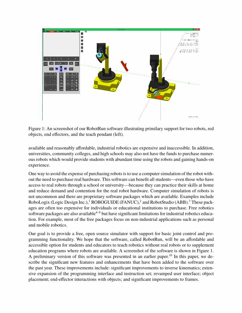
Figure 1: An screenshot of our RobotRun software illustrating primilary support for two robots, redobjects, end effectors, and the teach pendant (left).
available and reasonably affordable, industrial robotics are expensive and inaccessible. In addition,universities, community colleges, and high schools may also not have the funds to purchase numer-ous robots which would provide students with abundant time using the robots and gaining hands-onexperience.
One way to avoid the expense of purchasing robots is to use a computer simulation of the robot with-out the need to purchase real hardware. This software can benefit all students—even those who haveaccess to real robots through a school or university—because they can practice their skills at homeand reduce demand and contention for the real robot hardware. Computer simulation of robots isnot uncommon and there are proprietary software packages which are available. Examples includeRoboLogix (Logic Design Inc.),1 ROBOGUIDE (FANUC),2 and RobotStudio (ABB).3 These pack-ages are often too expensive for individuals or educational institutions to purchase. Free roboticssoftware packages are also available4–9 but have significant limitations for industrial robotics educa-tion. For example, most of the free packages focus on non-industrial applications such as personaland mobile robotics.
Our goal is to provide a free, open source simulator with support for basic joint control and pro-gramming functionality. We hope that the software, called RobotRun, will be an affordable andaccessible option for students and educators to teach robotics without real robots or to supplementeducation programs where robots are available. A screenshot of the software is shown in Figure 1.A preliminary version of this software was presented in an earlier paper.10 In this paper, we de-scribe the significant new features and enhancements that have been added to the software overthe past year. These improvements include: significant improvements to inverse kinematics; exten-sive expansion of the programming interface and instruction set; revamped user interface; objectplacement; end-effector interactions with objects; and significant improvements to frames.
The RobotRun software has been under development in the Computer Science department for thepast two years by undergraduate and graduate students at Michigan Tech under the direction of afaculty member. In addition, students and faculty from the university’s School of Technology havetested, provided feedback, and prioritized the features that were developed. Most of the developmenthas occurred during the summers. During the first summer, we developed an initial prototype of thesoftware which included a teach pendant, an industrial robot arm, basic robot movement controls,and a very limited programming interface. In the second summer, we made extensive improvementsto the software so that it is now fully capable of being used in educational settings. In the future, ourgoal is to identify and fix bugs as well as add new features. We plan fully support two simultaneousrobots in the software and make it run better on a variety of different devices. More informationabout planned future work is in Section 4.
3 RobotRun Overview
The RobotRun software was originally written in the Processing programming language. Process-ing is a Java-like language. As project grew, however, we transitioned the project to Java but still usesome of the Processing libraries. The source code for the package is publicly available at https://github.com/skuhl/RobotRun. The project website http://www.cs.mtu.edu/~kuhl/robotics/provides additional information about software.
3.1 User Interface
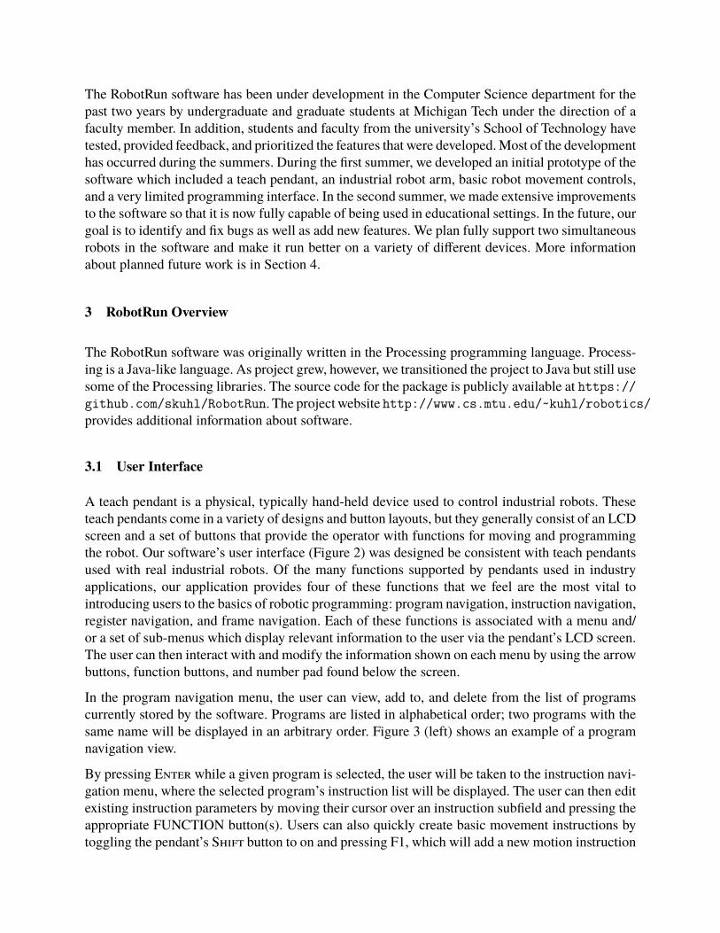
A teach pendant is a physical, typically hand-held device used to control industrial robots. Theseteach pendants come in a variety of designs and button layouts, but they generally consist of an LCDscreen and a set of buttons that provide the operator with functions for moving and programmingthe robot. Our software’s user interface (Figure 2) was designed be consistent with teach pendantsused with real industrial robots. Of the many functions supported by pendants used in industryapplications, our application provides four of these functions that we feel are the most vital tointroducing users to the basics of robotic programming: program navigation, instruction navigation,register navigation, and frame navigation. Each of these functions is associated with a menu and/or a set of sub-menus which display relevant information to the user via the pendant’s LCD screen.The user can then interact with and modify the information shown on each menu by using the arrowbuttons, function buttons, and number pad found below the screen.
In the program navigation menu, the user can view, add to, and delete from the list of programscurrently stored by the software. Programs are listed in alphabetical order; two programs with thesame name will be displayed in an arbitrary order. Figure 3 (left) shows an example of a programnavigation view.
By pressing Enter while a given program is selected, the user will be taken to the instruction navi-gation menu, where the selected program’s instruction list will be displayed. The user can then editexisting instruction parameters by moving their cursor over an instruction subfield and pressing theappropriate FUNCTION button(s). Users can also quickly create basic movement instructions bytoggling the pendant’s Shift button to on and pressing F1, which will add a new motion instruction
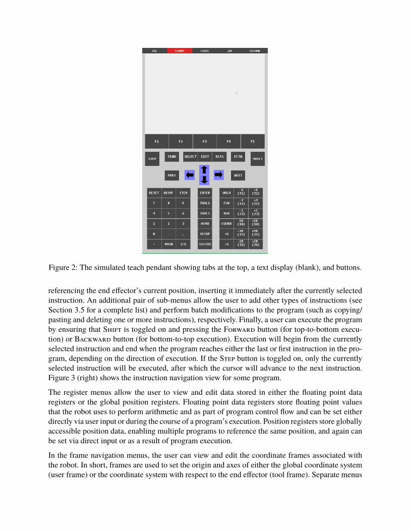
Figure 2: The simulated teach pendant showing tabs at the top, a text display (blank), and buttons.
referencing the end effector’s current position, inserting it immediately after the currently selectedinstruction. An additional pair of sub-menus allow the user to add other types of instructions (seeSection 3.5 for a complete list) and perform batch modifications to the program (such as copying/pasting and deleting one or more instructions), respectively. Finally, a user can execute the programby ensuring that Shift is toggled on and pressing the Forward button (for top-to-bottom execu-tion) or Backward button (for bottom-to-top execution). Execution will begin from the currentlyselected instruction and end when the program reaches either the last or first instruction in the pro-gram, depending on the direction of execution. If the Step button is toggled on, only the currentlyselected instruction will be executed, after which the cursor will advance to the next instruction.Figure 3 (right) shows the instruction navigation view for some program.
The register menus allow the user to view and edit data stored in either the floating point dataregisters or the global position registers. Floating point data registers store floating point valuesthat the robot uses to perform arithmetic and as part of program control flow and can be set eitherdirectly via user input or during the course of a program’s execution. Position registers store globallyaccessible position data, enabling multiple programs to reference the same position, and again canbe set via direct input or as a result of program execution.
In the frame navigation menus, the user can view and edit the coordinate frames associated withthe robot. In short, frames are used to set the origin and axes of either the global coordinate system(user frame) or the coordinate system with respect to the end effector (tool frame). Separate menus
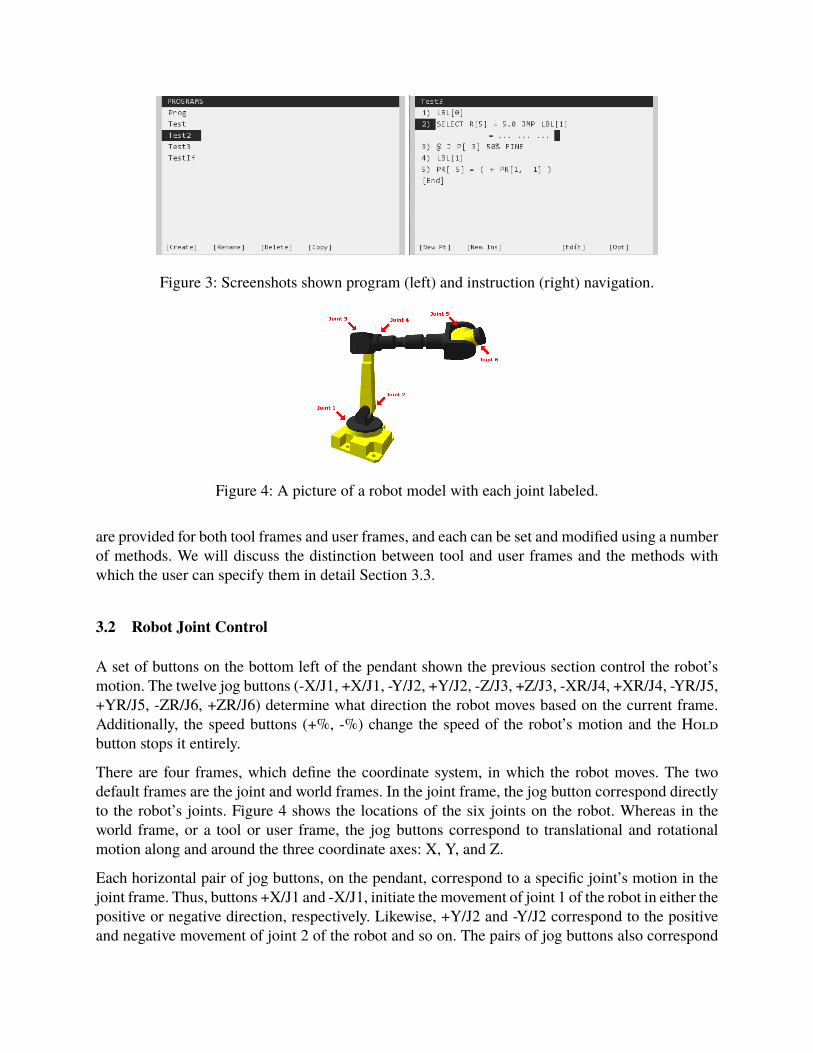
Figure 3: Screenshots shown program (left) and instruction (right) navigation.
Figure 4: A picture of a robot model with each joint labeled.
are provided for both tool frames and user frames, and each can be set and modified using a numberof methods. We will discuss the distinction between tool and user frames and the methods withwhich the user can specify them in detail Section 3.3.
3.2 Robot Joint Control
A set of buttons on the bottom left of the pendant shown the previous section control the robot’smotion. The twelve jog buttons (-X/J1, +X/J1, -Y/J2, +Y/J2, -Z/J3, +Z/J3, -XR/J4, +XR/J4, -YR/J5,+YR/J5, -ZR/J6, +ZR/J6) determine what direction the robot moves based on the current frame.Additionally, the speed buttons (+%, -%) change the speed of the robot’s motion and the Holdbutton stops it entirely.
There are four frames, which define the coordinate system, in which the robot moves. The twodefault frames are the joint and world frames. In the joint frame, the jog button correspond directlyto the robot’s joints. Figure 4 shows the locations of the six joints on the robot. Whereas in theworld frame, or a tool or user frame, the jog buttons correspond to translational and rotationalmotion along and around the three coordinate axes: X, Y, and Z.
Each horizontal pair of jog buttons, on the pendant, correspond to a specific joint’s motion in thejoint frame. Thus, buttons +X/J1 and -X/J1, initiate the movement of joint 1 of the robot in either thepositive or negative direction, respectively. Likewise, +Y/J2 and -Y/J2 correspond to the positiveand negative movement of joint 2 of the robot and so on. The pairs of jog buttons also correspond
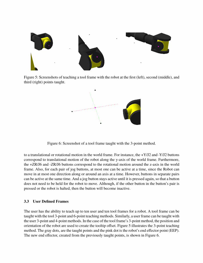
Figure 5: Screenshots of teaching a tool frame with the robot at the first (left), second (middle), andthird (right) points taught.
Figure 6: Screenshot of a tool frame taught with the 3-point method.
to a translational or rotational motion in the world frame. For instance, the +Y/J2 and -Y/J2 buttonscorrespond to translational motion of the robot along the y-axis of the world frame. Furthermore,the +ZR/J6 and -ZR/J6 buttons correspond to the rotational motion around the z-axis in the worldframe. Also, for each pair of jog buttons, at most one can be active at a time, since the Robot canmove in at most one direction along or around an axis at a time. However, buttons in separate pairscan be active at the same time. And a jog button stays active until it is pressed again, so that a buttondoes not need to be held for the robot to move. Although, if the other button in the button’s pair ispressed or the robot is halted, then the button will become inactive.
3.3 User Defined Frames
The user has the ability to teach up to ten user and ten tool frames for a robot. A tool frame can betaught with the tool 3-point and 6-point teaching methods. Similarly, a user frame can be taught withthe user 3-point and 4-point methods. In the case of the tool frame’s 3-point method, the position andorientation of the robot are used to create the tooltip offset. Figure 5 illustrates the 3-point teachingmethod. The gray dots, are the taught points and the pink dot is the robot’s end effector point (EEP).The new end effector, created from the previously taught points, is shown in Figure 6.
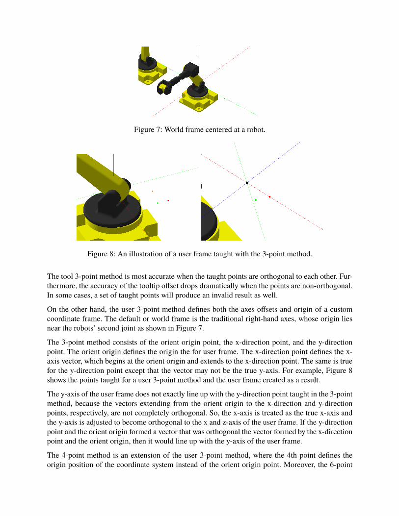
Figure 7: World frame centered at a robot.
Figure 8: An illustration of a user frame taught with the 3-point method.
The tool 3-point method is most accurate when the taught points are orthogonal to each other. Fur-thermore, the accuracy of the tooltip offset drops dramatically when the points are non-orthogonal.In some cases, a set of taught points will produce an invalid result as well.
On the other hand, the user 3-point method defines both the axes offsets and origin of a customcoordinate frame. The default or world frame is the traditional right-hand axes, whose origin liesnear the robots’ second joint as shown in Figure 7.
The 3-point method consists of the orient origin point, the x-direction point, and the y-directionpoint. The orient origin defines the origin the for user frame. The x-direction point defines the x-axis vector, which begins at the orient origin and extends to the x-direction point. The same is truefor the y-direction point except that the vector may not be the true y-axis. For example, Figure 8shows the points taught for a user 3-point method and the user frame created as a result.
The y-axis of the user frame does not exactly line up with the y-direction point taught in the 3-pointmethod, because the vectors extending from the orient origin to the x-direction and y-directionpoints, respectively, are not completely orthogonal. So, the x-axis is treated as the true x-axis andthe y-axis is adjusted to become orthogonal to the x and z-axis of the user frame. If the y-directionpoint and the orient origin formed a vector that was orthogonal the vector formed by the x-directionpoint and the orient origin, then it would line up with the y-axis of the user frame.
The 4-point method is an extension of the user 3-point method, where the 4th point defines theorigin position of the coordinate system instead of the orient origin point. Moreover, the 6-point
method for creating a tool frame combines the tool 3-point method, which specifies the robot’send effector offset with the user 3-point method, which defines the axes of the coordinate system,in which the robot moves. Either frame can be created with a direct entry as well, where the userspecifies the origin (or end effector offset in the case of a tool frame) (X, Y, Z) and axes offset (W,P, R) values explicitly.
When a tool or user frame is active, the active robot will move with respect to the active frame.Additionally, the axes of the active frame are displayed instead of the axes of the world frame.When a user frame is active, the axes are displayed at the origin position of the user frame, whereaswhen a tool frame is active, the axes are centered at the robot’s end effector position.
3.4 Inverse Kinematics
Typically, when one of the robot’s joint motors is actuated, the resulting motion causes the end ef-fector to move along an arc. To produce linear motion, the software must be able to calculate changesto multiple joint angles to keep the end effector moving along a straight line while maintaining thecorrect orientation. To accomplish this, we employ a process called inverse kinematics to calculatethe joint angles necessary to move the end effector to a given position, then instruct the software torepeatedly move the end effector to new locations along a straight line.
We implemented a well-known algorithm11 to perform our inverse kinematic calculations. First, wecompute a matrix of the partial derivatives of the robot’s joint angles with respect to the end effectorposition, called the Jacobian matrix. In other words, each row of the Jacobian matrix is associatedwith one of the robot’s joints; the data in each column of a given row then corresponds with thecomponents of the vector tangent to that joint’s arc of motion at the current location of the end ef-fector. To compute this matrix, rather than performing the computationally expensive calculationsto obtain the exact partial derivatives for each joint angle, we approximate these vectors by usingour forward kinematic equations to calculate hypothetical end effector positions at small individualoffsets to our current joint angles (+/- 1 degree). When we multiply a change in joint angles by theJacobian matrix, the result is the change in the end effector position. For inverse kinematics, wewish to solve the problem in reverse: We know how we want to change the end effector position andwant to know how to change the angles for each joint. By inverting the Jacobian, we can thereforecalculate the joint angles from the change in end effector position. Since the Jacobian is often notinvertible, we instead compute the pseudoinverse of it. Then, we can multiply the target positionby the Jacobian pseudoinverse to obtain the approximate joint angles necessary to reach our targetposition. To obtain the pseudoinverse of our Jacobian matrix, we use an implementation of SingularValue Decomposition (SVD) provided by the Apache Commons Math library.12 If the first iterationof this process does not produce a sufficiently accurate result (<1% error from position/ orientationtarget), we can perform these calculations again from the resulting position in an attempt to improveour positional accuracy. If the algorithm does not produce an acceptable result within a set numberof iterations, we determine that the target position cannot be reached and halt the robot withoutupdating its joint angles.

3.5 Robot Programming and Instruction Set
In order to allow the user to create easily repeated patterns of motion for the robot to follow, wehave created a simple set of control and logic instructions that can be used to program the roboticarm. The simulator’s programming language is similar to the Karel programming language used inFANUC robots. Instructions include:
• Motion type instructions allow the user to save a position or series of positions that will,when executed, cause the robot to move its end effector to each position in the order thatthey appear in the program. These instructions can be modified to produce joint-rotationalmovement, linear movement, or circular movement. Circular movement allows movementalong an arbitrary arc specified by the robot’s current position and two distinct, user-definedpoints. Additionally, the user can specify the speed at which the movement will be performedand whether or not the robot should apply any smoothing between points.
• Register type instructions allow the user to modify position or data registers by providingan arithmetic expression, the result of which will be stored in the given register once theexpression is evaluated.
• Frame type instructions set the current user or tool frame index.
• Label instructions are unique tags that identify a specific location within the program. Whilethey do not perform any operation in and of themselves, they can be used by jump instructionsto alter the order of execution in a program (see below). Labels are identified by a numericID and, crucially, no two labels within the same program may have the same ID.
• Jump instructions allow the program to execute in an order other than top-to-bottom orbottom-to-top. A jump may skip certain instructions, or may return to a previously executedinstruction to repeat certain operations. Jumps can be conditional (as in if and select state-ments), or they can be unconditional. After jumping to a given label, execution continuesfrom either the instruction immediately below or immediately above that label, depending onthe direction of execution.
• Call instructions allow a program to transfer execution to another program. When a programis called via a call instruction, the robot will begin executing the called program startingwith the first instruction in that program. Once the callee program has finished executing, thecaller program will continue its own execution from the instruction immediately below orimmediately above the call instruction, depending on the direction of execution.
• If statements provide basic control flow, allowing the user to define a boolean expressionfor the program to evaluate; if the expression evaluates to true, the program will then executesome user defined action (either a jump or a call operation), otherwise execution falls throughto the next instruction.
• Select statements, like if statements, provide a system of control flow that allows the userto specify an action and a condition under which that action will be performed. However,rather than providing an entire expression to determine whether or not the given action willbe performed, a select statement simply takes a register (position or data) and compares the
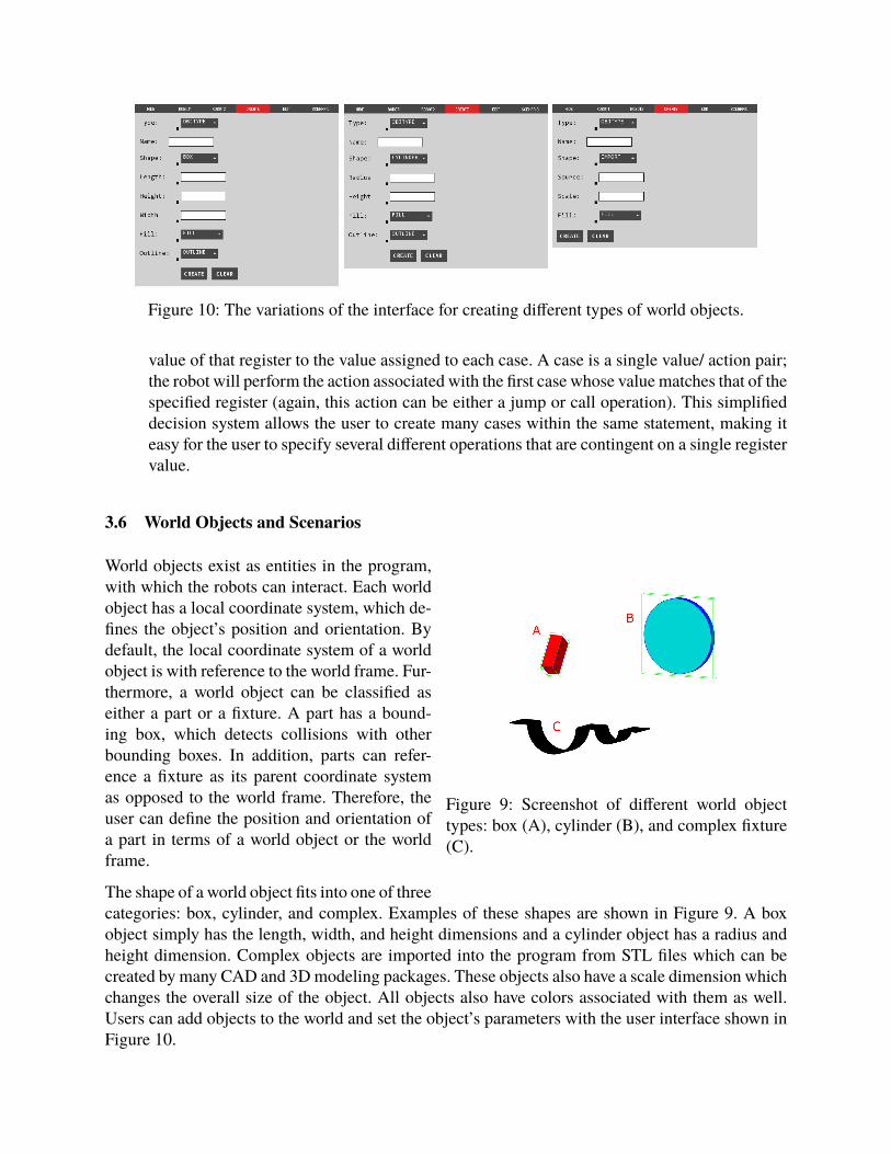
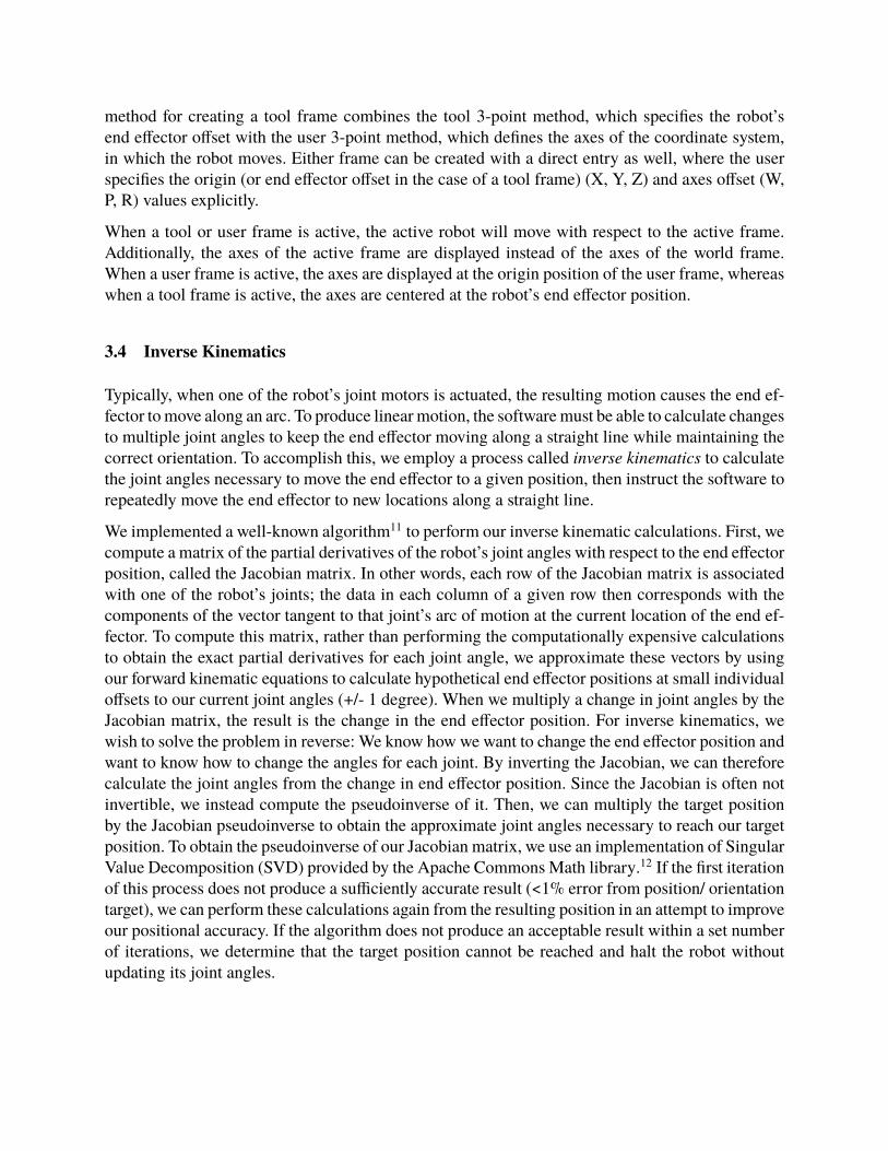
Figure 10: The variations of the interface for creating different types of world objects.
value of that register to the value assigned to each case. A case is a single value/ action pair;the robot will perform the action associated with the first case whose value matches that of thespecified register (again, this action can be either a jump or call operation). This simplifieddecision system allows the user to create many cases within the same statement, making iteasy for the user to specify several different operations that are contingent on a single registervalue.
3.6 World Objects and Scenarios
Figure 9: Screenshot of different world objecttypes: box (A), cylinder (B), and complex fixture(C).
World objects exist as entities in the program,with which the robots can interact. Each worldobject has a local coordinate system, which de-fines the object’s position and orientation. Bydefault, the local coordinate system of a worldobject is with reference to the world frame. Fur-thermore, a world object can be classified aseither a part or a fixture. A part has a bound-ing box, which detects collisions with otherbounding boxes. In addition, parts can refer-ence a fixture as its parent coordinate systemas opposed to the world frame. Therefore, theuser can define the position and orientation ofa part in terms of a world object or the worldframe.
The shape of a world object fits into one of threecategories: box, cylinder, and complex. Examples of these shapes are shown in Figure 9. A boxobject simply has the length, width, and height dimensions and a cylinder object has a radius andheight dimension. Complex objects are imported into the program from STL files which can becreated by many CAD and 3D modeling packages. These objects also have a scale dimension whichchanges the overall size of the object. All objects also have colors associated with them as well.Users can add objects to the world and set the object’s parameters with the user interface shown inFigure 10.
Each screenshot is of the same base interface, which changes based on the defined shape of the ob-ject in order to accommodate the dimensions of different world object shapes. The local coordinatesystem of a world object is not defined upon the creation of the object, instead a world object isinitially placed at a position next to one of the robots on the positive end of the x-axis. The positionand orientation of a world object can be edited along with the dimensions of the object after theyhave been created.
World objects are associated with a scenario defined by the user. A scenario is simply a way togroup world objects together as opposed to simply grouping all world objects into a single defaultscenario. Scenarios are independent the robots and are defined in a separate interface much likethe creation of world objects. Each scenario is given a unique name amongst all scenarios whenit is created and only one scenario can be active at one time. Also, any world objects created areautomatically associated with the active scenario.
3.7 Collision Detection
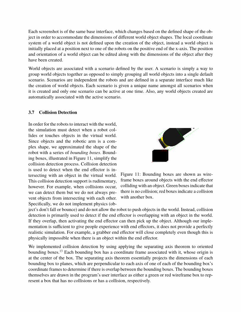
Figure 11: Bounding boxes are shown as wire-frame boxes around objects with the end effectorcolliding with an object. Green boxes indicate thatthere is no collision; red boxes indicate a collisionwith another box.
In order for the robots to interact with the world,the simulation must detect when a robot col-lides or touches objects in the virtual world.Since objects and the robotic arm is a com-plex shape, we approximated the shape of therobot with a series of bounding boxes. Bound-ing boxes, illustrated in Figure 11, simplify thecollision detection process. Collision detectionis used to detect when the end effector is in-tersecting with an object in the virtual world.This collision detection support is rudimentary,however. For example, when collisions occur,we can detect them but we do not always pre-vent objects from intersecting with each other.Specifically, we do not implement physics (ob-ject’s don’t fall or bounce) and do not allow the robot to push objects in the world. Instead, collisiondetection is primarily used to detect if the end effector is overlapping with an object in the world.If they overlap, then activating the end effector can then pick up the object. Although our imple-mentation is sufficient to give people experience with end effectors, it does not provide a perfectlyrealistic simulation. For example, a grabber end effector will close completely even though this isphysically impossible when there is an object within the end effector.
We implemented collision detection by using applying the separating axis theorem to orientedbounding boxes.13 Each bounding box has a coordinate frame associated with it, whose origin isat the center of the box. The separating axis theorem essentially projects the dimensions of eachbounding box to planes, which are perpendicular to each axis of one of each of the bounding box’scoordinate frames to determine if there is overlap between the bounding boxes. The bounding boxesthemselves are drawn in the program’s user interface as either a green or red wireframe box to rep-resent a box that has no collisions or has a collision, respectively.
4 Future Work
In the upcoming year, we plan to collect feedback from students at Bay de Noc Community Collegeand Michigan Tech. Based on feedback from them and other users, we will improve the softwareand the documentation to address problems and shortcomings. We also plan to implement two moresignificant features: The control of two robots and the addition of a vision system.
4.1 Two robots
As shown in Figure 1, we have already implemented preliminary support for two robots in our soft-ware. Full support for two robots, however, is incomplete. We are still working on the developmentof the user interface to control both robots, the ability to run programs on robots simultaneously,and the ability to allow a programmer to specify how programs on both robots should run in con-cert with each other. Furthermore, additional work is necessary for the software to detect collisionsbetween robots and respond appropriately.
4.2 Vision system
Many robots are outfitted with vision systems to help robots to detect the location of parts or thetype of the part. Currently, our software does not simulate any kind of vision system. We plan to,however, simulate some of the features available in industrial robotics vision systems in RobotRun.Since our software package is fully aware of where the robots and all objects are, we expect thatit will be possible to implement this feature without needing to implement any computer visionalgorithms that would be necessary to implement this system on a real robot. For example, oursoftware can easily determine if the end effector is picking up a red object without the need for anyimage processing techniques.
5 Conclusions
RobotRun is a promising new tool which we hope that educators, students, and displaced workerswill be able to leverage to prepare for an increasingly automated manufacturing industry. Our soft-ware fills a gap between expensive proprietary software packages for industrial robotics and exist-ing open-source packages that are primarily aimed at personal and mobile robots. RobotRun is nowfunctional and ready for use. In the future we plan to fix any remaining bugs, finish support for tworobots, and implement a vision system. We hope that this software will help transform and enableindustrial robotics education in high schools, community colleges, and universities—particularlyfor Electrical Engineering Technology degree programs.
6 Acknowledgements
This project is supported by National Science Foundation grant DUE-1501335.

References
1 Robologix, logic design inc. https://www.robologix.com/. Accessed: 2016-01-31.2 Roboguide, fanuc america corporation. http://robot.fanucamerica.com/products/vision-software/
roboguide-simulation-software.aspx. Accessed: 2016-01-31.3 Robotstudio, abb. http://new.abb.com/products/robotics/robotstudio. Accessed: 2016-01-31.4 Illah Reza Nourbakhsh. The educational impact of the robotic autonomy mobile robotics course. Technical report,
Carnegie Mellon University, 2003.5 Namin Shin and Sangah Kim. Learning about, from, and with robots: Students’ perspectives. In Robot and Human
interactive Communication, 2007. RO-MAN 2007. The 16th IEEE International Symposium on, pages 1040–1045.IEEE, 2007.
6 Stefano Carpin, Mike Lewis, Jijun Wang, Stephen Balakirsky, and Chris Scrapper. Usarsim: a robot simulator forresearch and education. In Robotics and Automation, 2007 IEEE International Conference on, pages 1400–1405.IEEE, 2007.
7 Francesco Mondada, Michael Bonani, Xavier Raemy, James Pugh, Christopher Cianci, Adam Klaptocz, StephaneMagnenat, Jean-Christophe Zufferey, Dario Floreano, and Alcherio Martinoli. The e-puck, a robot designed foreducation in engineering. In Proceedings of the 9th conference on autonomous robot systems and competitions,volume 1, pages 59–65. IPCB: Instituto Politécnico de Castelo Branco, 2009.
8 Seul Jung. Experiences in developing an experimental robotics course program for undergraduate education. Edu-cation, IEEE Transactions on, 56(1):129–136, 2013.
9 Gazebo, open source robotics foundation. http://gazebosim.org/. Accessed: 2016-01-31.10 Scott A Kuhl, Aleksandr Sergeyev, James Walker, Shashank Barkur Lakshmikanth, Mark Highum, Nasser Alaraje,
Ruimin Zhang, and Mark Bradley Kinney. Enabling affordable industrial robotics education through simulation. In2016 ASEE Annual Conference & Exposition, New Orleans, Louisiana, June 2016. ASEE Conferences.
11 Samual R. Buss. Introduction to Inverse Kinematics with Jacobian Transpose, Pseudoinverse and Damped LeastSquares methods. https://www.math.ucsd.edu/~sbuss/ResearchWeb/ikmethods/iksurvey.pdf, October2009.
12 The Apache Software Foundation. Apache commons math. http://commons.apache.org/proper/commons-math/, 2016.
13 Johnny Huynh. Separating axis theorem for oriented bounding boxes. http://www.jkh.me/files/tutorials/SeparatingAxisTheoremforOrientedBoundingBoxes.pdf, September 2009.