Enhancements to cavity quantum electrodynamics system · Enhancements to cavity quantum...
7
REVISTA MEXICANA DE F ´ ISICA S 57 (3) 29–35 JULIO 2011 Enhancements to cavity quantum electrodynamics system A.D. Cimmarusti, J.A. Crawford, D.G. Norris and L.A. Orozco Joint Quantum Institute, Department of Physics, University of Maryland and National Institute of Standards and Technology, College Park, MD 20742-4111, U.S.A. Recibido el 21 de enero de 2011; aceptado el 17 de febrero de 2011 We show the planned upgrade of a cavity QED experimental apparatus. The system consists of an optical cavity and an ensemble of ultracold 85 Rb atoms coupled to its mode. We propose enhancements to both. First, we document the building process for a new cavity, with a planned finesse of ∼20000. We address problems of maintaining mirror integrity during mounting and improving vibration isolation. Second, we propose improvements to the cold atom source in order to achieve better optical pumping and control over the flux of atoms. We consider a 2-D optical molasses for atomic beam deflection, and show computer simulation results for evaluating the design. We also examine the possibility of all-optical atomic beam focusing, but find that it requires unreasonable experimental parameters. Keywords: Cavity QED; optical cavity; optical molasses; laser lens; atomic beam deflection. Mostramos mejoras planeadas a un aparato experimental de electrodin´ amica cu´ antica en cavidades. Este sistema consta de una cavidad ´ optica y un ensamble de ´ atomos de 85 Rb ultra-fr´ ıos acoplados con el modo de la cavidad. Proponemos mejoras a ambas. Primeramente, documentamos el proceso de construcci ´ on de una nueva cavidad, con finesa estimada de ∼20000. Tratamos los problemas del mantenimiento de la integridad de los espejos durante el montaje y el mejoramiento del aislamiento ante vibraciones. En segundo lugar, proponemos mejoras a la fuente de ´ atomos fr´ ıos para lograr mejor bombeo ´ optico y control sobre el flujo de ´ atomos. Consideramos una molasa ´ optica en 2-D para desviar el haz de ´ atomos y mostramos resultados de simulaciones en computadora para evaluar el dise˜ no. Tambi´ en examinamos la posibilidad de enfocar nuestro haz at ´ omico s ´ olo ´ opticamente, pero vemos que para ello se requieren par´ ametros experimentales irrazonables. Descriptores: Electrodin´ amica cu´ antica en cavidades; cavidad ´ optica; molasa ´ optica; lente l´ aser; deflecci ´ on haz at ´ omico. PACS: 42.15.Eq; 42.50.Pq; 32.60.+i 1. Introduction The simplest realization of a cavity quantum electrodynamic system consists of a single material fermion coupled to a bo- son field. Our work in the optical regime couples Rb atoms and a finite number of modes of an optical cavity [1]. These systems have numerous applications in quantum information science [2-5], and also enable the study of quantum optics effects difficult to observe in free space [6-12]. Our current cavity QED experimental setup incorporates two independent vacuum chamber components: a spheri- cal hexagon and a cube (See Fig. 1). The former houses an unbalanced Magneto-Optical Trap (MOT), from which we obtain a Low-Velocity Intense Source (LVIS) of 85 Rb atoms [13]. The MOT uses a pair of coils to generate a quadrupole magnetic field, with two retro-reflected laser beams in the horizontal plane, and a third along the axis of the strong magnetic field gradient (vertical direction). At the bottom of the chamber, the vertical beam strikes a gold mir- ror and quarter-wave plate that have a 1.5-mm diameter hole, yielding a region of unbalanced laser intensity that pushes out a beam of cold atoms. Directly below the hexagon lies a cubic chamber which contains the optical cavity. Atoms propagate 3-4 cm through the mirror to the cavity and are op- tically pumped to a desired m state en route. A fraction of the atoms pass between the cavity mirrors (2.2 mm spacing) and couple to the TEM 00 mode (1/e field radius 56 μm) for ∼ 5 μs before striking the bottom of the vacuum chamber. FIGURE 1. Current vacuum chamber (not drawn to scale). Unbal- anced MOT (red beams) by hole in mirror creates LVIS. The current arrangement has room for improvement in several fronts: Light from the vertical MOT beam propagates collinearly with the atoms, complicating the desired optical pumping distribution and driving the atoms weakly while they are coupled to the cavity mode. We are unable to access the regime of collective strong coupling in this system, due
Transcript of Enhancements to cavity quantum electrodynamics system · Enhancements to cavity quantum...
REVISTA MEXICANA DE FISICA S57 (3) 29–35 JULIO 2011
Enhancements to cavity quantum electrodynamics system
A.D. Cimmarusti, J.A. Crawford, D.G. Norris and L.A. OrozcoJoint Quantum Institute, Department of Physics,
University of Maryland and National Institute of Standards and Technology,College Park, MD 20742-4111, U.S.A.
Recibido el 21 de enero de 2011; aceptado el 17 de febrero de 2011
We show the planned upgrade of a cavity QED experimental apparatus. The system consists of an optical cavity and an ensemble of ultracold85Rb atoms coupled to its mode. We propose enhancements to both. First, we document the building process for a new cavity, with a plannedfinesse of∼20000. We address problems of maintaining mirror integrity during mounting and improving vibration isolation. Second, wepropose improvements to the cold atom source in order to achieve better optical pumping and control over the flux of atoms. We considera 2-D optical molasses for atomic beam deflection, and show computer simulation results for evaluating the design. We also examine thepossibility of all-optical atomic beam focusing, but find that it requires unreasonable experimental parameters.
Keywords: Cavity QED; optical cavity; optical molasses; laser lens; atomic beam deflection.
Mostramos mejoras planeadas a un aparato experimental de electrodinamica cuantica en cavidades. Este sistema consta de una cavidadoptica y unensamble de atomos de85Rb ultra-frıos acoplados con el modo de la cavidad. Proponemos mejoras a ambas. Primeramente,documentamos el proceso de construccion de una nueva cavidad, con finesa estimada de∼20000. Tratamos los problemas del mantenimientode la integridad de los espejos durante el montaje y el mejoramiento del aislamiento ante vibraciones. En segundo lugar, proponemos mejorasa la fuente deatomos frıos para lograr mejor bombeooptico y control sobre el flujo deatomos. Consideramos una molasaoptica en 2-Dpara desviar el haz deatomos y mostramos resultados de simulaciones en computadora para evaluar el diseno. Tambien examinamos laposibilidad de enfocar nuestro haz atomico solo opticamente, pero vemos que para ello se requieren parametros experimentales irrazonables.
Descriptores: Electrodinamica cuantica en cavidades; cavidadoptica; molasaoptica; lente laser; defleccion haz atomico.
PACS: 42.15.Eq; 42.50.Pq; 32.60.+i
1. Introduction
The simplest realization of a cavity quantum electrodynamicsystem consists of a single material fermion coupled to a bo-son field. Our work in the optical regime couples Rb atomsand a finite number of modes of an optical cavity [1]. Thesesystems have numerous applications in quantum informationscience [2-5], and also enable the study of quantum opticseffects difficult to observe in free space [6-12].
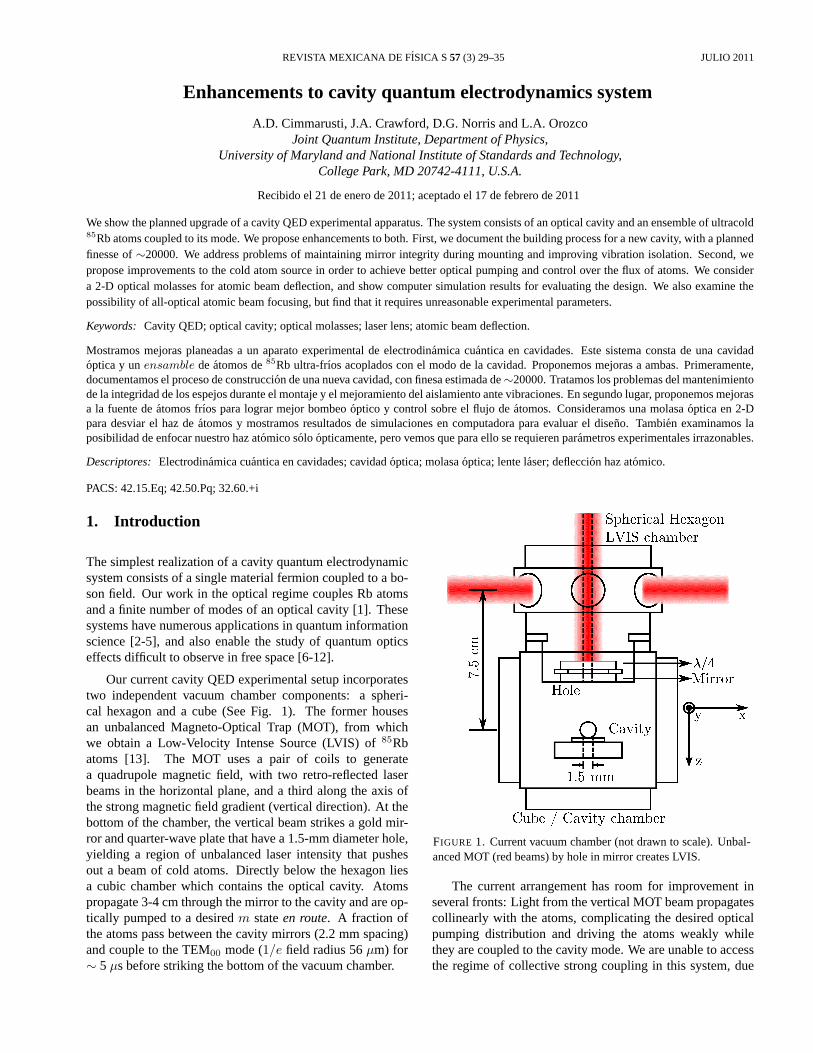
Our current cavity QED experimental setup incorporatestwo independent vacuum chamber components: a spheri-cal hexagon and a cube (See Fig. 1). The former housesan unbalanced Magneto-Optical Trap (MOT), from whichwe obtain a Low-Velocity Intense Source (LVIS) of85Rbatoms [13]. The MOT uses a pair of coils to generatea quadrupole magnetic field, with two retro-reflected laserbeams in the horizontal plane, and a third along the axis ofthe strong magnetic field gradient (vertical direction). At thebottom of the chamber, the vertical beam strikes a gold mir-ror and quarter-wave plate that have a 1.5-mm diameter hole,yielding a region of unbalanced laser intensity that pushesout a beam of cold atoms. Directly below the hexagon liesa cubic chamber which contains the optical cavity. Atomspropagate 3-4 cm through the mirror to the cavity and are op-tically pumped to a desiredm stateen route. A fraction ofthe atoms pass between the cavity mirrors (2.2 mm spacing)and couple to the TEM00 mode (1/e field radius 56µm) for∼ 5 µs before striking the bottom of the vacuum chamber.
FIGURE 1. Current vacuum chamber (not drawn to scale). Unbal-anced MOT (red beams) by hole in mirror creates LVIS.
The current arrangement has room for improvement inseveral fronts: Light from the vertical MOT beam propagatescollinearly with the atoms, complicating the desired opticalpumping distribution and driving the atoms weakly whilethey are coupled to the cavity mode. We are unable to accessthe regime of collective strong coupling in this system, due
30 A.D. CIMMARUSTI, J.A. CRAWFORD, D.G. NORRIS AND L.A. OROZCO
to the small number of atoms that couple fully to the cavitymode. This is primarily due to the distribution of transversevelocities of the atoms coming from the LVIS, which resultsin a broadening spatial profile and lower atom density as thebeam propagates. To increase the single atom coupling wedecrease the mode volume by a factor of two and keep thedecay rate of the cavity increasing the finesse also by a factorof two. However, the reduction of the volume complicatesthe collective strong coupling.
The structure of the paper is as follows: Sec. 2 talks aboutthe progress in the construction of the new optical cavity. InSec. 3, we discuss deflection of an LVIS by a 2-D optical mo-lasses (OM). We explore the possibility of focusing an atomicbeam in Sec.4, and we end with conclusions in Sec. 5.
2. Building the optical cavity
At the heart of every optical cavity QED apparatus lies a highfinesse (low loss) resonator. As the optical transmission co-efficients for the mirrors used in the resonator may be as lowas a few parts per million, reducing the absorptive losses tothis level is a great experimental challenge. Our present cav-ity (decay rateκ/2π = 2.8× 10⁶ s−1 and finesse of 11,000)suffers from higher than expected losses, reducing its finesseby about a factor of two from the intended value (∼25,000,as calculated using the reflectivity of the mirrors). We be-lieve the losses are due to adhesive residue inadvertently de-posited on the mirror surfaces during construction, as well asthe aging of the high-reflectivity coatings over the nearly twodecades since deposition. We are constructing a new cavitywith small and well-characterized losses, as well as slightlystronger coupling to the atoms and enhanced vibration isola-tion.
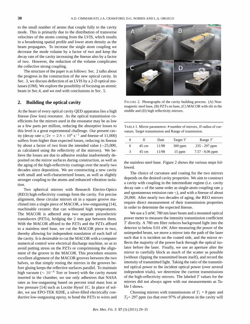
Two spherical mirrors with Research Electro-Optics(REO) high-reflectivity coatings form the cavity. For precisealignment, these circular mirrors sit in a square groove ma-chined into a single piece of MACOR, a low-outgassing [14],machinable ceramic that can withstand high temperatures.The MACOR is adhered atop two separate piezoelectrictransducers (PZTs), bridging the 2 mm gap between them.With the MACOR affixed to the PZTs and the PZTs affixedto a stainless steel base, we cut the MACOR piece in two,thereby allowing for independent translation of each half ofthe cavity. It is desireable to cut the MACOR with a computernumerical control wire electrical discharge machine, so as toavoid putting stress on the PZTs or comprimising the align-ment of the groove in the MACOR. This procedure ensuresexcellent alignment of the MACOR grooves between the twohalves, so that simply resting the mirrors in the grooves be-fore gluing keeps the reflective surfaces parallel. To maintainhigh vacuum (∼ 10−8 Torr or lower) with the cavity mountinserted in the chamber, we use only adhesives that NASArates as low-outgassing based on percent total mass loss atlow pressure [14] such as Loctite Hysol 1C. In place of sol-der, we use EPO-TEK H20E, a silver-filled electrically con-ductive low-outgassing epoxy, to bond the PZTs to wires and
FIGURE 2. Photographs of the cavity building process. (A) Non-magnetic steel base, (B) PZTs on base, (C) MACOR with slit in themiddle and (D) high reflectivity mirrors.
TABLE I. Mirror parameters: # number of mirrors,R radius of cur-vature, Target transmission and Range of trasmission.
# R Date TargetT RangeT
6 45 cm 11/98 300 ppm 235 - 297 ppm
3 45 cm 11/98 15 ppm 7.57 - 8.06 ppm
the stainless steel base. Figure 2 shows the various steps fol-lowed.
The choice of curvature and coating for the two mirrorsdepends on the desired cavity properties. We aim to constructa cavity with coupling in the intermediate regime (i.e. cavitydecay rateκ of the same order as single-atom coupling rategand spontaneous emission rateγ), and with a finesse of about20,000. After nearly two decades of aging, the REO mirrorsrequire direct measurement of their transmission propertiesin order to determine the expected finesse.
We use a 5 mW, 780 nm laser beam and a mounted opticalpower meter to measure the intensity transmission coefficientT directly. A 780 nm filter reduces background light into thedetector to below 0.01 nW. After measuring the power of theunimpeded beam, we move a mirror into the path of the lasersuch that it is incident on the coated side, and the mirror re-flects the majority of the power back through the optical iso-lator before the laser. Finally, we use an aperture after themirror to carefully block as much of the scatter as possible(without clipping the transmitted beam itself), and record theintensity of transmitted light. Taking the ratio of the transmit-ted optical power to the incident optical power (over severalindependent trials), we determine the current transmissionsof the high-reflectivity mirrors. The labeledT values for themirrors did not always agree with our measurements as Ta-ble I shows.
Choosing mirrors with transmissions ofT1 = 8 ppm andT2= 297 ppm (so that over 97% of photons in the cavity will
Rev. Mex. Fıs. S 57 (3) (2011) 29–35
ENHANCEMENTS TO CAVITY QUANTUM ELECTRODYNAMICS SYSTEM 31
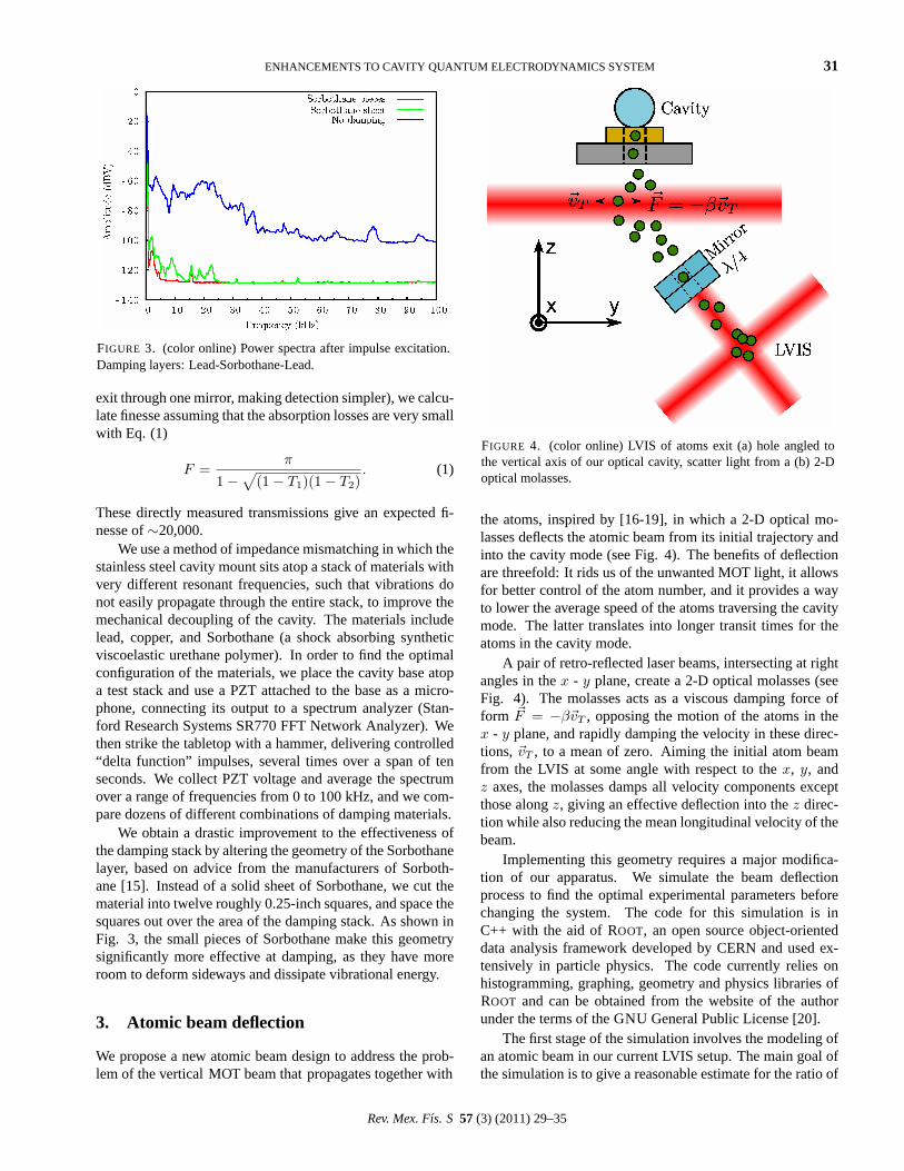
FIGURE 3. (color online) Power spectra after impulse excitation.Damping layers: Lead-Sorbothane-Lead.
exit through one mirror, making detection simpler), we calcu-late finesse assuming that the absorption losses are very smallwith Eq. (1)
F =π
1−√
(1− T1)(1− T2). (1)
These directly measured transmissions give an expected fi-nesse of∼20,000.
We use a method of impedance mismatching in which thestainless steel cavity mount sits atop a stack of materials withvery different resonant frequencies, such that vibrations donot easily propagate through the entire stack, to improve themechanical decoupling of the cavity. The materials includelead, copper, and Sorbothane (a shock absorbing syntheticviscoelastic urethane polymer). In order to find the optimalconfiguration of the materials, we place the cavity base atopa test stack and use a PZT attached to the base as a micro-phone, connecting its output to a spectrum analyzer (Stan-ford Research Systems SR770 FFT Network Analyzer). Wethen strike the tabletop with a hammer, delivering controlled“delta function” impulses, several times over a span of tenseconds. We collect PZT voltage and average the spectrumover a range of frequencies from 0 to 100 kHz, and we com-pare dozens of different combinations of damping materials.
We obtain a drastic improvement to the effectiveness ofthe damping stack by altering the geometry of the Sorbothanelayer, based on advice from the manufacturers of Sorboth-ane [15]. Instead of a solid sheet of Sorbothane, we cut thematerial into twelve roughly 0.25-inch squares, and space thesquares out over the area of the damping stack. As shown inFig. 3, the small pieces of Sorbothane make this geometrysignificantly more effective at damping, as they have moreroom to deform sideways and dissipate vibrational energy.
3. Atomic beam deflection
We propose a new atomic beam design to address the prob-lem of the vertical MOT beam that propagates together with
FIGURE 4. (color online) LVIS of atoms exit (a) hole angled tothe vertical axis of our optical cavity, scatter light from a (b) 2-Doptical molasses.
the atoms, inspired by [16-19], in which a 2-D optical mo-lasses deflects the atomic beam from its initial trajectory andinto the cavity mode (see Fig. 4). The benefits of deflectionare threefold: It rids us of the unwanted MOT light, it allowsfor better control of the atom number, and it provides a wayto lower the average speed of the atoms traversing the cavitymode. The latter translates into longer transit times for theatoms in the cavity mode.
A pair of retro-reflected laser beams, intersecting at rightangles in thex - y plane, create a 2-D optical molasses (seeFig. 4). The molasses acts as a viscous damping force ofform ~F = −β~vT , opposing the motion of the atoms in thex - y plane, and rapidly damping the velocity in these direc-tions,~vT , to a mean of zero. Aiming the initial atom beamfrom the LVIS at some angle with respect to thex, y, andz axes, the molasses damps all velocity components exceptthose alongz, giving an effective deflection into thez direc-tion while also reducing the mean longitudinal velocity of thebeam.
Implementing this geometry requires a major modifica-tion of our apparatus. We simulate the beam deflectionprocess to find the optimal experimental parameters beforechanging the system. The code for this simulation is inC++ with the aid ofROOT, an open source object-orienteddata analysis framework developed by CERN and used ex-tensively in particle physics. The code currently relies onhistogramming, graphing, geometry and physics libraries ofROOT and can be obtained from the website of the authorunder the terms of theGNU General Public License [20].
The first stage of the simulation involves the modeling ofan atomic beam in our current LVIS setup. The main goal ofthe simulation is to give a reasonable estimate for the ratio of
Rev. Mex. Fıs. S 57 (3) (2011) 29–35
32 A.D. CIMMARUSTI, J.A. CRAWFORD, D.G. NORRIS AND L.A. OROZCO
atoms that couple to the cavity mode to the total number of
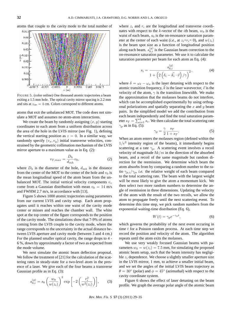
FIGURE 5. (color online) One thousand atomic trajectories a beamexiting a 1.5 mm hole. The optical cavity mirror spacing is 2.2 mmand sits atzcav = 4 cm. Colors correspond to different atoms.
atoms that exit the unbalanced MOT. The code does not sim-ulate a MOT and assumes no atom-atom interactions.
We create the beam by randomly assigning(x, y) startingcoordinates to each atom from a uniform distribution acrossthe area of the hole in the LVIS mirror (see Fig. 1), definingthe vertical starting position asz = 0. In a similar way, werandomly specify(vx, vy) initial transverse velocities, con-strained by the geometric collimation mechanism of the LVISmirror aperture to a maximum value as in Eq. (2):
vT,max =Dh
dmhv0, (2)
whereDh is the diameter of the hole,dmh is the distancefrom the center of the MOT to the center of the hole andv0 isthe mean longitudinal speed of the atom beam from the un-balanced MOT. The initial vertical velocity componentsvz
come from a Gaussian distribution with meanv0 = 14 m/sand FWHM 2.7 m/s, in accordance with [13].
Figure 5 shows 1000 atomic trajectories using parametersfrom our current LVIS and cavity setup. Each atom prop-agates until it reaches within one waist of the cavity modecenter or misses and reaches the chamber wall. The whitespot at the top center of the figure corresponds to the positionof the cavity mode. The simulations show that 7-9% of atomscoming from the LVIS couple to the cavity mode, where therange corresponds to the uncertainty in the actual distance be-tween LVIS aperture and cavity mode (between 3 and 4 cm.)For the planned smaller optical cavity, the range drops to 4 -6 %, down by approximately a factor of two as expected fromthe mode volume.
We next simulate the atomic beam deflection proposal.We follow the treatment of [21] for the calculation of the scat-tering rates in steady-state for a two-level atom in the pres-ence of a laser. We give each of the four beams a transverseGaussian profile as in Eq. (3):
s(g)0,i = s0
(w0
w(zi)
)2
exp[−2
(r2i
w2(zi)
)], (3)
wherezi andri are the longitudinal and transverse coordi-nates with respect to thek-vector of theith beam,w0 is thewaist of each beam,s0 is the on-resonance saturation param-eter at the center of each waist (i.e., at zi=ri= 0), andw(zi)is the beam spot size as a function of longitudinal positionalong each beam.s(g)
0,i is the Gaussian beam correction to theon-resonance saturation parameter. We use it to calculate thesaturation parameter per beam for each atom as Eq. (4):
si =s(g)0,i
1 +(2
(δi − ~ki · ~v
)/γ
)2 , (4)
whereδ = ω` − ωa is the laser detuning with respect to theatomic transition frequency,~k is the laser wavevector,~v is thevelocity of the atom,γ is the transition linewidth. We makethe approximation that the molasses beams do not interfere,which can be accomplished experimentally by using orthog-onal polarizations and spatially separating thex andy beampairs. In the simplified model we add the contribution fromeach beam independently and find the total saturation param-etersT =
∑4i=1 si. We then calculate the total scattering rate
γp as in Eq. (5):γp =
γ
2sT
1 + sT, (5)
When an atom enters the molasses region (defined within the1/e2 intensity region of the beams), it immediately beginsscattering at a rateγp. A scattering event involves a recoilvelocity of magnitude~k/m in the direction of the absorbedbeam, and a recoil of the same magnitude but random di-rection for the reemission. We determine which beam theatom absorbs from by comparing a random number to the ra-tio γp,i/γp, i.e. the relative weight of each beam comparedto the total scattering rate. The beam with the largest weightwill be most likely to give the atom a momentum kick. Wethen select two more random numbers to determine the an-gle of reemission in three dimensions. Updating the velocityof the atom with the result of the two recoils, we allow theatom to propagate freely until the next scattering event. Todetermine this time step, we pick random numbers from theexponential waiting-time distribution (Eq. 6),
W (t) = γpe−γpt, (6)
which governs the probability of the next event occuring intime t for a Poisson random process. At each time step werecord the position and velocity of the atom. The algorithmrepeats until the atom exits the molasses.
We use very weakly focused Gaussian beams with pa-rametersw0 = w(zi) = 7.5 mm, for simulating the proposedatomic beam setup, such that the beam intensity has negligi-blezi dependence. We choose a slightly smaller aperture sizein the LVIS mirror, 1 mm, to achieve a smaller initial beam,and we set the angles of the initial LVIS beam trajectory asθ = 30◦ (polar) andφ = 45◦ (azimuthal) with respect to thecavity coordinate system.
Figure 6 shows the effect of laser detuning on the beamprofile. We graph the average polar angle of the atomic beam
Rev. Mex. Fıs. S 57 (3) (2011) 29–35
ENHANCEMENTS TO CAVITY QUANTUM ELECTRODYNAMICS SYSTEM 33
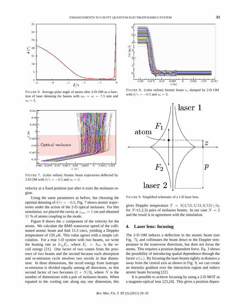
FIGURE 6. Average polar angle of atoms after 2-D OM as a func-tion of laser detuning for beams withw0 = w = 7.5 mm ands0 = 3.
FIGURE 7. (color online) Atomic beam trajectories deflected by2-D OM with δ/γ = −0.5 ands0 = 3.
velocity at a fixed position just after it exits the molasses re-gion.
Using the same parameters as before, but choosing theoptimal detuning ofδ/γ = −0.5, Fig. 7 shows atomic trajec-tories under the action of the 2-D optical molasses. For thissimulation, we placed the cavity atzcav = 1 cm and obtained11 % of atoms coupling to the mode.
Figure 8 shows thex component of the velocity for theatoms. We calculate the RMS transverse speed of the colli-mated atomic beam and find 15.3 cm/s, yielding a Dopplertemperature of 120µK. This value agrees with a simple cal-culation. For a true 1-D system with two beams, we writethe heating rate as4γpEr, where Er = ~ωr is the re-coil energy [21]. One factor of two comes from the pres-ence of two beams and the second because each absorptionand re-emission cycle involves two recoils in that dimen-sion. In three dimensions, the recoil energy from isotropicre-emission is divided equally among all directions, so thissecond factor of two becomes (1 + N/3), whereN is thenumber of dimensions with a pair of molasses beams. Whenequated to the cooling rate along any one dimension, this
FIGURE 8. (color online) Atomic beamvx damped by 2-D OMwith δ/γ = −0.5 ands0 = 3.
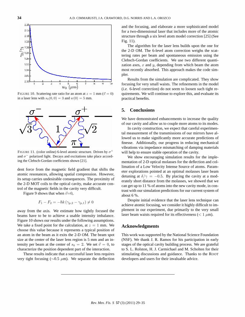
FIGURE 9. Simplified schematic of a 1-D laser lens.
gives Doppler temperatureT = ~(4/12, 5/12, 6/12)γ/kb
for N=(1,2,3) pairs of molasses beams. In our caseN = 2and the result is in agreement with the simulation.
4. Laser lens: focusing
The 2-D OM induces a deflection in the atomic beam (seeFig. 7), and collimates the beam down to the Doppler tem-perature in the transverse directions, but does not focus theatoms. This requires a position dependent force. Eq. 3 showsthe possibility of introducing spatial dependence through thefactorw(zi). By focusing the laser beams tightly at distancepaway from the central axis as shown in Fig. 9, we can createan intensity gradient over the interaction region and induceatomic beam focusing [22].
It is possible to achieve focusing by using a 2-D MOT asa magneto-optical lens [23,24]. This gives a position depen-
Rev. Mex. Fıs. S 57 (3) (2011) 29–35
34 A.D. CIMMARUSTI, J.A. CRAWFORD, D.G. NORRIS AND L.A. OROZCO
FIGURE 10. Scattering rate ratio for an atom atz = 1 mm (~v = 0)in a laser lens withs0(0, 0) = 3 andw(0) = 5 mm.
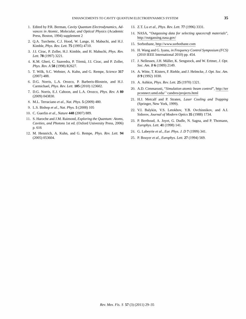
FIGURE 11. (color online) 6-level atomic structure. Driven byσ+
andσ− polarized light. Decays and excitations take place accord-ing the Clebsch-Gordan coefficients shown [21].
dent force from the magnetic field gradient that shifts theatomic resonances, allowing spatial compression. However,its setup carries undesirable consequences. The proximity ofthe 2-D MOT coils to the optical cavity, make accurate con-trol of the magnetic fields in the cavity very difficult.
Figure 9 shows that when~v=0,
F1 − F2 = −~k (γp,2 − γp,1) 6= 0
away from the axis. We estimate how tightly focused thebeams have to be to achieve a usable intensity imbalance.Figure 10 shows our results under the following assumptions.We take a fixed point for the calculation, atz = 1 mm. Wechoose this value because it represents a typical position ofan atom in the beam as it exits the 2-D OM. The beam spotsize at the center of the laser lens region is 5 mm and an in-tensity per beam at the center ofs0 = 2. We set~v = 0, tocharacterize the position dependent part of the interaction.
These results indicate that a successful laser lens requiresvery tight focusing (∼0.5 µm). We separate the deflection
and the focusing, and elaborate a more sophisticated modelfor a two-dimensional laser that includes more of the atomicstructure through a six level atom model correction [25] (SeeFig. 11).
The algorithm for the laser lens builds upon the one forthe 2-D OM. The 6-level atom correction weighs the scat-tering rates per beam and spontaneous emission using theClebsch-Gordan coefficients. We use two different quanti-zation axes,x andy, depending from which beam the atommost recently absorbed. This approach makes the code sim-pler.
Results from the simulation are complicated. They showfocusing for very small waists. The refinements in the model(i.e. 6-level correction) do not seem to loosen such tight re-quirements. We will continue to explore this, and evaluate itspractical benefits.
5. Conclusions
We have demonstrated enhancements to increase the qualityof our cavity and allow us to couple more atoms to its modes.
In cavity construction, we expect that careful experimen-tal measurement of the transmissions of our mirrors have al-lowed us to make significantly more accurate predictions offinesse. Additionally, our progress in reducing mechanicalvibrations via impedance mismatching of damping materialswill help to ensure stable operation of the cavity.
We show encouraging simulation results for the imple-mentation of 2-D optical molasses for the deflection and col-limation of a Low Velocity Intense Source of atoms. Param-eter explorations pointed at an optimal molasses laser beamdetuning atδ/γ = −0.5. By placing the cavity at a mod-erately short distance from the molasses, we showed that wecan get up to 11 % of atoms into the new cavity mode, in con-trast with our simulation predictions for our current system ofabout 6 %.
Despite initial evidence that the laser lens technique canachieve atomic focusing, we consider it highly difficult to im-plement in our experiment, due primarily to the very smalllaser beam waists required for its effectiveness (< 1 µm).
Acknowledgments
This work was supported by the National Science Foundation(NSF). We thank J. R. Ramos for his participation in earlystages of the optical cavity building process. We are gratefulto S. L. Rolston, H. J. Carmichael and M. Scholten for theirstimulating discussions and guidance. Thanks to theROOT
developers and users for their invaluable advice.
Rev. Mex. Fıs. S 57 (3) (2011) 29–35
ENHANCEMENTS TO CAVITY QUANTUM ELECTRODYNAMICS SYSTEM 35
1. Edited by P.R. Berman,Cavity Quantum Electrodynamics, Ad-vances in Atomic, Molecular, and Optical Physics(AcademicPress, Boston, 1994) supplement 2
2. Q.A. Turchette, C.J. Hood, W. Lange, H. Mabuchi, and H.J.Kimble, Phys. Rev. Lett.75 (1995) 4710.
3. J.I. Cirac, P. Zoller, H.J. Kimble, and H. Mabuchi,Phys. Rev.Lett.78 (1997) 3221.
4. K.M. Gheri, C. Saavedra, P. Torma, J.I. Cirac, and P. Zoller,Phys. Rev. A58 (1998) R2627.
5. T. Wilk, S.C. Webster, A. Kuhn, and G. Rempe,Science317(2007) 488.
6. D.G. Norris, L.A. Orozco, P. Barberis-Blostein, and H.J.Carmichael,Phys. Rev. Lett.105(2010) 123602.
7. D.G. Norris, E.J. Cahoon, and L.A. Orozco,Phys. Rev. A80(2009) 043830.
8. M.L. Terracianoet al., Nat. Phys.5 (2009) 480.
9. L.S. Bishopet al., Nat. Phys.5 (2008) 105
10. C. Guerlinet al., Nature448(2007) 889.
11. S. Haroche and J.M. Raimond,Exploring the Quantum: Atoms,Cavities, and Photons1st ed. (Oxford University Press, 2006)p. 616
12. M. Hennrich, A. Kuhn, and G. Rempe,Phys. Rev. Lett.94(2005) 053604.
13. Z.T. Lu et al., Phys. Rev. Lett.77 (1996) 3331.
14. NASA, “Outgassing data for selecting spacecraft materials”,http://outgassing.nasa.gov/
15. Sorbothane, http://www.sorbothane.com
16. H. Wang and G. Iyanu,in Frequency Control Symposium (FCS)(2010 IEEE International 2010) pp. 454.
17. J. Nellessen, J.H. Muller, K. Sengstock, and W. Ertmer,J. Opt.Soc. Am. B6 (1989) 2149.
18. A. Witte, T. Kisters, F. Riehle, and J. Helmcke,J. Opt. Soc. Am.B 9 (1992) 1030.
19. A. Ashkin, Phys. Rev. Lett.25 (1970) 1321.
20. A.D. Cimmarusti, “Simulation atomic beam control”, http://terpconnect.umd.edu/∼candres/projects.html
21. H.J. Metcalf and P. Straten,Laser Cooling and Trapping(Springer, New York, 1999).
22. V.I. Balykin, V.S. Letokhov, Y.B. Ovchinnikov, and A.I.Sidorov,Journal of Modern Optics35 (1988) 1734.
23. P. Berthoud, A. Joyet, G. Dudle, N. Sagna, and P. Thomann,Europhys. Lett.41 (1998) 141.
24. G. Labeyrieet al., Eur. Phys. J. D7 (1999) 341.
25. P. Bouyeret al., Europhys. Lett.27 (1994) 569.
Rev. Mex. Fıs. S 57 (3) (2011) 29–35