Enhanced Performance Zinc Coating for Steel in...
55
NCHRP IDEA Program Enhanced Performance Zinc Coating for Steel in Concrete Final Report for NCHRP IDEA Project 174 Prepared by: Neal S. Berke, Ph.D. Tourney Consulting Group, LLC November 2016
Transcript of Enhanced Performance Zinc Coating for Steel in...
NCHRP IDEA Program
Enhanced Performance Zinc Coating for Steel in Concrete
Final Report for
NCHRP IDEA Project 174
Prepared by:
Neal S. Berke, Ph.D.
Tourney Consulting Group, LLC
November 2016
Innovations Deserving Exploratory Analysis (IDEA) Programs
Managed by the Transportation Research Board
This IDEA project was funded by the NCHRP IDEA Program.
The TRB currently manages the following three IDEA programs:
The NCHRP IDEA Program, which focuses on advances in the design, construction, and
maintenance of highway systems, is funded by American Association of State Highway and
Transportation Officials (AASHTO) as part of the National Cooperative Highway Research
Program (NCHRP).
The Safety IDEA Program currently focuses on innovative approaches for improving railroad
safety or performance. The program is currently funded by the Federal Railroad
Administration (FRA). The program was previously jointly funded by the Federal Motor
Carrier Safety Administration (FMCSA) and the FRA.
The Transit IDEA Program, which supports development and testing of innovative concepts
and methods for advancing transit practice, is funded by the Federal Transit Administration
(FTA) as part of the Transit Cooperative Research Program (TCRP).
Management of the three IDEA programs is coordinated to promote the development and testing
of innovative concepts, methods, and technologies.
For information on the IDEA programs, check the IDEA website (www.trb.org/idea). For
questions, contact the IDEA programs office by telephone at (202) 334-3310.
IDEA Programs
Transportation Research Board
500 Fifth Street, NW
Washington, DC 20001
The project that is the subject of this contractor-authored report was a part of the Innovations Deserving
Exploratory Analysis (IDEA) Programs, which are managed by the Transportation Research Board
(TRB) with the approval of the National Academies of Sciences, Engineering, and Medicine. The
members of the oversight committee that monitored the project and reviewed the report were chosen for
their special competencies and with regard for appropriate balance. The views expressed in this report
are those of the contractor who conducted the investigation documented in this report and do not
necessarily reflect those of the Transportation Research Board; the National Academies of Sciences,
Engineering, and Medicine; or the sponsors of the IDEA Programs.
The Transportation Research Board; the National Academies of Sciences, Engineering, and Medicine;
and the organizations that sponsor the IDEA Programs do not endorse products or manufacturers. Trade
or manufacturers’ names appear herein solely because they are considered essential to the object of the
investigation.

Enhanced Performance Zinc Coating for Steel in Concrete
IDEA Program Final Report
Contract Number: NCHRP-174
Prepared for the IDEA Program
Transportation Research Board
The National Academics
Neal S. Berke, Ph.D.
Tourney Consulting Group, LLC
November 4, 2016

NCHRP IDEA PROGRAM COMMITTEE
CHAIR
DUANE BRAUTIGAM
Consultant
MEMBERS
CAMILLE CRICHTON-SUMNERS
New Jersey DOT
AGELIKI ELEFTERIADOU
University of Florida
ANNE ELLIS
Arizona DOT
ALLISON HARDT
Maryland State Highway Administration
JOE HORTON
California DOT
MAGDY MIKHAIL
Texas DOT
TOMMY NANTUNG
Indiana DOT
MARTIN PIETRUCHA
Pennsylvania State University
VALERIE SHUMAN
Shuman Consulting Group LLC
L.DAVID SUITS North American Geosynthetics Society
JOYCE TAYLOR
Maine DOT
FHWA LIAISON DAVID KUEHN
Federal Highway Administration
TRB LIAISON RICHARD CUNARD
Transportation Research Board
COOPERATIVE RESEARCH PROGRAM STAFF
STEPHEN PARKER
Senior Program Officer
IDEA PROGRAMS STAFF STEPHEN R. GODWIN Director for Studies and Special Programs
JON M. WILLIAMS
Program Director, IDEA and Synthesis Studies
INAM JAWED Senior Program Officer
DEMISHA WILLIAMS
Senior Program Assistant EXPERT REVIEW PANEL
MARIO PAREDEDS, Florida DOT
RAY BOTTENBERG, Oregon DOT
MIKE BROWN, Georgia DOT
MIKE DALLAIRE, FHWA
TED HOPWOOD, Kentucky Trans. Research Center
STEVE KAHL, Michigan DOT
DARYL LITTLE, US Bureau of Reclamation

ACKNOWLEDGMENTS
We wish to acknowledge the following people and organizations that helped on this project:
Our review committee:
• Mario Paredes, Chairman—TRI Environmental (Florida DOT)
• Ray Bottenberg—Oregon DOT
• Mike Brown—Virginia Transportation Research Center
• Mike Dallaire—FHWA, Eastern Lands
• Ted Hopwood—Kentucky Transportation Research Center
• Steve Kahl—Michigan DOT
• Daryl Little—U.S. Bureau of Reclamation
The NCHRP for funding this work and our liaison Dr. Inam Jawed, Distek NA for additional funding and support, and
the technicians and engineers at Tourney Consulting Group who assisted on this project. We wish to also acknowledge
the contributions of Dr. Adam Rudy, who played a key role at the start of the project.


TABLE OF CONTENTS
1 EXECUTIVE SUMMARY ........................................................................................................................................... 1
2 KEY FINDINGS AND SIGNIFICANT RESULTS ...................................................................................................... 2
1 IDEA PRODUCT .......................................................................................................................................................... 3
1.1 INTRODUCTION ............................................................................................................................................... 3
1.2 PRODUCT ........................................................................................................................................................... 3
1.3 POTENTIAL IMPACT ON TRANSPORTATION PRACTICE ........................................................................ 3
2 CONCEPT AND INNOVATION ................................................................................................................................. 3
3 INVESTIGATION ........................................................................................................................................................ 4
3.1 MATERIAL TESTED ......................................................................................................................................... 4
3.2 EXPERIMENTAL PROGRAM .......................................................................................................................... 6
3.2.1 Concrete Properties .......................................................................................................................................... 6
3.2.2 Description of Tests ......................................................................................................................................... 9
3.3 RESULTS AND DISCUSSIONS ...................................................................................................................... 12
3.3.1 Cracked Minibeams ....................................................................................................................................... 12
3.3.2 U-Bends ......................................................................................................................................................... 36
4 PLANS FOR IMPLEMENTATION ........................................................................................................................... 43
5 CONCLUSIONS ......................................................................................................................................................... 44
6 INVESTIGATOR PROFILES ..................................................................................................................................... 45
7 GLOSSARY AND REFERENCES ............................................................................................................................. 45
7.1 GLOSSARY....................................................................................................................................................... 45
7.2 REFERENCES ................................................................................................................................................... 45
APPENDIX A .................................................................................................................................................................... 47
A1 COMPOSITION OF STEEL USED .......................................................................................................................... 47
A2 REINFORCING BARS ............................................................................................................................................. 48

1
1 EXECUTIVE SUMMARY
Emphasis on the long-term performance of bridges and other department of transportation (DOT) structures exposed to
deicing or marine salts requires improving the corrosion resistance of embedded steel as well as the performance of the
concrete. Stainless steel reinforcing bars are currently being specified in these structures, but with reduced permeability in
the concrete, more cost-effective alternatives are attractive. Concerns with these alternatives are typically about corrosion
at cracks in concrete as well as damage to the coating if coated steel is utilized.
This report evaluates thermal zinc diffusion (TZD) coatings on reinforcing bars, which provide the alloy bond found in
hot-dipped galvanized (HDG) coatings with several advantages: a) tighter thickness tolerances, b) better ductility, c)
applicability to high tensile strength steels, and d) less likelihood of embrittling the steel substrate. These coatings
(ASTM A1059) have corrosion performance surpassing that of HDG, but uses so far have been for fasteners and other
hardware in atmospheric and marine exposures.
Figure ES 1 shows the HDG versus the TZD bars. The TZD coating is a zinc-iron alloy versus the mostly zinc coating
with HDG. The coating is more uniform for TZD bars.
Figure ES 1 The HDG versus the TZD bars.
One benefit of the program is the development of an accelerated test method that is applicable to high-quality concrete.
This study determined corrosion performance in good quality concrete cracked in flexure with periodic loading to abrade
the coatings, to capture the two predominant failure mechanisms for coated steels. Both straight and bent bars were
evaluated as well as another set of U-bend specimens for stress corrosion. Steels evaluated were black steel, HDG,
epoxy-coated steel, 2304 Stainless Steel (SS), low chromium ASTM 1035 steel, and the TZD. An epoxy coating was
manually applied to the TZD bars to evaluate a coated version of the product (TZE). Figure ES 2 shows the beam
specimens and a schematic of a U-bend specimen.
FIGURE ES 2 Cracked beam specimens (a) and schematic of U-bend specimen (b).

2
2 KEY FINDINGS AND SIGNIFICANT RESULTS
The performance of the corrosion-resistant reinforcing bars was significantly better than the control black bars. Extension
of testing to two years made it easier to differentiate performance between the bars. The performance of reinforcements
in the two test methods was different. This is somewhat due to the very quick ingress of chlorides in the U-bend
specimens to all of the bar area, due to low cover and a higher water-to-cement ratio (w/c) = 0.5, whereas, even though
the minibeams were cracked, the reinforcing bars were pulling the crack closed near the bar and cover was higher, so
total chloride ingress was slower. Analysis of the chloride data showed that at the reinforcing bar level in the cracked
concrete with 0.4 w/c and higher cover, the chloride levels were equivalent or lower than those in the U-bends. The
overall relative corrosion resistance rankings in the cracked beam test were:
Black bar < HDG < A1035 low chromium < TZE ≈ TZD < ECR, 2304 SS
This supports the basis of the project that TZD reinforcing steel could improve the corrosion performance of steel in
concrete. For the U-bend specimens, the HDG performed better than TZD, but it is believed that this is mainly a result of
the higher w/c and lower cover which let chloride in too fast preventing the TZD specimen to adequately form a
protective passive coating. The HDG coating was thicker and had a chromate treatment which helped it to passivate.
The epoxy-coated TZD bars (TZE) had lower corrosion currents. The damage on the bars was comparable to the TZD
in the beam test but did help in the U-bend tests. The coating was not optimized (brushed versus fusion bonded, not
formulated for concrete use), which implies that performance could improve with a commercially applied suitable
coating.
A summary of the key advantages found for the TZD bars follows:
Improved corrosion resistance versus HDG at a lower coating thickness (2.6 versus 6.9 mils):
- Potentially lower initial and life cycle cost due to thinner coating and improved performance.
Statistically significant lower chloride concentration at the bottom reinforcing bar level for TZD than the other
reinforcing bars in the cracked beam tests, indicating that the bars affected cracking below the bar, even though
chloride contents were equivalent at the top bars.
Corrosion potential shift at corrosion initiation similar to that of black bar unlike HDG:
- Easier to evaluate corrosion condition in the field
- Better planning for bridge maintenance.
Corrosion performance of TZD versus HDG reversed in better quality (lower w/c and higher cover) concrete.
Potential to meet long service life requirements using high performance concrete with TZD or TZE versus using
stainless steel bars in conventional concrete for an overall lower life-cycle cost.
The cracked beam tests had several important findings:
Chloride concentrations decrease with depth if the bar crossing the crack has not exceeded its yield stress, i.e.,
the bars close the cracks, even when wedged to stay open as the bars are in tension as demonstrated by the crack
closing if the wedge is removed. At larger crack sides the bar could yield or lose bond to the concrete and not be
in tension. In this case the crack would not close if the wedge was removed.
Localized corrosion; that is, microcell corrosion on the bars can be significantly greater than the corrosion
estimated from just the macrocell current.
Though the epoxy-coated steel (ECR) performed well, corrosion was initiating on bars without major defects
such as intentionally induced damage; for example, drill holes, by the end of the testing.
Most important is that the test method uses flexural cracks versus pulled smooth wedges which is more typical
of cracks in concrete.
Based on the results of this study, the principal investigator (PI) recommends further work with DOTs to initiate trial
testing in the field. The cracked beam method looks promising as a test method to evaluate corrosion-resistant reinforcing
bars, high-performance concrete, surface treatments and a combination of these. The PI recommends that the flexural
cracked beam test be developed into an AASHTO provisional test method specification.

3
1 IDEA PRODUCT
1.1 INTRODUCTION
Current and future designs for bridges and other reinforced concrete structures exposed to deicing or marine chlorides
requires improved corrosion resistance of the reinforcing steels in combination with higher quality concrete. Several
stainless steel alloys are believed to have good performance, but the material costs are several times that of conventional
black steel. In addition, though only the outer surface of the steel needs protection, the entire bar is made of alloys using
premium raw materials.
A more sustainable approach considering initial material costs would be to use black steel with a protective coating,
such as in hot-dipped galvanized (HDG) or epoxy-coated bars (ECR). If these bars provide enhanced corrosion
protection, there can be a reduction in the overall life cycle cost versus black steel or stainless steel, using holistic
approaches addressing the overall performance of the bar as a function of concrete properties and concrete cover over the
bars, as performed in life-cycle modeling. These bars are subjected to mechanical damage in placement and in use to due
to cyclic loading of the concrete and the development of cracking. The potential for hydrogen embrittlement and coating
application temperature limits the use of hot-dipped galvanized coating on some higher strength reinforcing bars that are
desired for more efficient designs. Epoxy-coated reinforcement requires longer embedment lengths, and its lower bond
might offset the use of higher strength steel bars.
1.2 PRODUCT
The product that was the focus of investigation is a reinforcing bar with a thermal zinc diffusion (TZD) coating, with and
without a supplemental organic coating. This TZD coating should have excellent bond to the steel as does the HDG
coating, but is applied at lower temperatures than hot-dip galvanizing. This allows TZD coatings to be applied to higher
strength steels without negative effects on the strength properties. It has a more porous surface than hot-dipped
galvanized so that it should have a better bond to the concrete and is an excellent substrate for paint. The coating is
significantly thinner using less zinc.
1.3 POTENTIAL IMPACT ON TRANSPORTATION PRACTICE
TZD-coated reinforcement will have a significantly lower initial cost than stainless steel reinforcement, and can be
applied to all strength grades of steel, allowing for potential additional savings where the designer can use higher tensile
strengths to reduce the amount of reinforcing bars needed. When used with higher strength bars and lower permeability
concrete, TZD could potentially lower the overall upfront and service life costs for bridges versus alternative reinforcing
bar options.
2 CONCEPT AND INNOVATION
A process of applying zinc to steel via thermal diffusion has been developed by Distek, NA, and has been in commercial
use since 1993. The bars in this study were produced in the United States and coated in Michigan. The coating deposition
temperatures (700–780°F) are lower than that in hot-dip galvanizing (840°F), but zinc-iron intermetallic phases form
resulting in a metallurgical alloy bond between the zinc overlay and the steel substrate. The process results in a
metallurgical conversion of the exterior surface into a porous zinc/iron alloy. The thermal diffusion process provides a
very uniform coating that retains the original geometry of the part, as can be seen in Figure 1. It is hard and wear-
resistant, and can withstand the rough handling and storage conditions generally expected in the field, as well as
exhibiting ductility in bending and forming. Also, the thermal process is not susceptible to hydrogen embrittlement.
Tests comparing the performance in severe salt environments with and without abrasion show a 5 to 10 times
improvement in performance with the TZD-coated steel versus HDG steel. Steel coated by this method is covered by
ASTM A 1059 Standard Specification for Zinc Alloy Thermo-Diffusion Coatings (TDC) on Steel Fasteners, Hardware,
and Other Products. Bars can be produced in lengths of 60 ft.

4
FIGURE 1 Example of how TZD coating maintains the original geometry. Cross section of the nut shows that the
internal threads are coated and maintain the thread geometry with a 25-micron coating (bright surface).
Applying TZD to reinforcing bars is a recent application for this technology. The coating is not as thick as the zinc
coating in HDG reinforcing bars, which helps to reduce cost and should help in workability. It has excellent abrasion
resistance, based on current uses on chains used by the U.S. Navy, and the surface porosity should improve reinforcement
bond to the concrete. The higher porosity should be beneficial for a two-component coating where the top coat would be
an organic coating.
As noted earlier, the coating is very uniform even over ribs in the bars and is a low-temperature process. This could
potentially be applied to higher strength reinforcement. This could potentially result in improved cracking behavior and a
reduction in the cross-sectional requirements for the steel. The TZD coating applied to higher strength (grades 75 to 100)
reinforcing bars could provide cost savings (less steel required), offsetting the initial upfront cost of the bars, where
designs allow for reducing the required reinforcement for higher tensile strength reinforcement.
3 INVESTIGATION
3.1 MATERIAL TESTED
The project review committee suggested replacing the dual coated (zinc plus epoxy) reinforcing bars with ASTM 1035
bars, because dual coated bars were not available. The materials evaluated are shown in Table 1. All of the bars were No.
4, Grade 60 except for the ASTM A1035 bars, which were Grade 100, and the SS bars, which were Grade 75.
TABLE 1 Materials evaluated
Material Specification(s) Designation
Thermal zinc diffusion coated steel ASTM A615 TZD
Epoxy-painted, thermal zinc diffusion coated steel ASTM A615 TZE
Black Bar ASTM A615 BB
Epoxy-coated bar ASTM A706 &
A775
ECR
Hot-dipped galvanized bar ASTM A706 &
A767 (Class 1)
HDG
2304 Stainless steel bar (UNS S32304) ASTM A955 SS
Low-carbon chromium steel bar ASTM A1035 X35
Unified Numbering System for Metals and Alloys.
The compositions of the reinforcing bars are presented in Appendix A1. The BB and TZD reinforcing bars used the
same steel (Nucor, Heat #BR1110214401 June 2011). HDG and ECR bars used the same steel (NUCOR, Heat
#KN1310678101, December 2013). The BB bars used alone and as the substrate for TZD met ASTM A 615, the BB used
as the substrate for the HDG and ECR bars met ASTM A706. The HDG coating was specified to meet ASTM A767
Class 1 and the ECR to meet ASTM A775. The 2304 SS met the requirements of ASTM A955. The TZE bars were
coated manually, with a commercial epoxy (Sherwin Williams Macropoxy 646-100) by the Kentucky Transportation

5
Center. Photos of the bars are in Appendix 2. There was some rust on the X35 bars as received. Loose rust was removed
with wire brushing as can be seen in the photos in Appendix A2.
The TZD, HDG, and ECR coating thicknesses are shown in Table 2. The delta scope (magnetic method) readings did
not provide good results for the zinc coatings, due to the rib pattern on the bars, which was close to the probe size.
Optical microscopy on ground and polished to 1 micron, cross sections was used to provide a better estimate of the
coating and the differences between the two methods were less for the organic coatings. Six to 11 valley and six to 11
web locations were used and averaged. The overall averages combining both locations were used. For coating loss
analysis on the TZD and HDG bars, a chemical removal technique was employed as discussed in the experimental and
results sections. Figure 2 shows the microstructures of the coated bars.
TABLE 2 Coating thicknesses for TZD, TZE, HDG, and ECR Bars
Bar Coating Thickness (mils)
Delta Scope Microscopy
Average Std. Deviation Average Std. Deviation
TZD 0.8 0.4 2.6 0.4
TZE 10.4 3.6 9.8 4.0
HDG 2.7 0.6 6.9 3.8
ECR 7.2 1.1 9.3 2.5

6
FIGURE 2 Microstructures of the coated bars.
3.2 EXPERIMENTAL PROGRAM
This section describes the properties of the concrete tested, the corrosion specimens, and the corrosion test methods used.
Two kinds of specimens were used to evaluate the corrosion performance of TZD and TZE relative to the commercial
reinforcing bars in the program. Cracked beam specimens were produced with a good quality concrete mix and
reinforcement cover as described below, to simulate cracking that would occur in field concrete. These minibeams were
periodically fatigued in flexure, as would be the experience on a bridge deck, even though it is not a part of the deck
design in AASHTO LRFD 9.5.3, since fatigue could potentially affect corrosion performance.
Additionally, U-bend specimens were produced at a higher water-to-cement ratio as compared to the minibeams (w/c)
and lower concrete cover as compared to the minibeams to obtain results quicker and to evaluate the bars under stress.
The original duration of the test program was to be one year of testing. However, an extension to allow for 2 years of
testing was granted because better differentiation of corrosion performance was needed. This can be seen in the following
sections.
3.2.1 Concrete Properties
3.2.1.1 Concrete Properties of the Beam Specimens
The concrete mixtures were the same for all the bars evaluated. Specimens were produced for two of the bar types from
each batch, except a batch of the TZE bars that were received one month later. Table 3 shows the mixture design for the
concrete used to produce the minibeams specimens.

7
The concrete properties are given in Table 4. There are some minor variations in properties among the four batches
used to produce the seven sets of beams. As can be seen in Table 4, the compressive strengths at 28 days were over 5000
psi, and the flexural strengths were over 800 psi, which is representative of a good quality air-entrained concrete mixture.
Flexural strengths for the reinforced beams reflect load at cracking. These values are not as accurate as the ASTM C 78
flexural strengths on the unreinforced beams, since the reinforced beams did not break, which made it harder to define the
point of the first crack.
TABLE 3 Concrete mixture design for the
cracked minibeams
Component Units Minibeam
Mixture
Cement I/II pcy 658
Natural Sand pcy 1217
Coarse Aggregate 3/4" pcy 1825
Water pcy 263
w/c pcy 0.4
Air % 6
Slump inch 4 to 6
Unit Weight pcf 146.8
The concrete conductivity was determined according to ASTM C 1760, at 14 days when the specimens were tested
under flexure and at 28 days. Table 5 shows the conductivities (milli-Siemans/meter, mS/m) as well as the corresponding
ASTM C1202 Rapid Chloride values assuming no heating in the C1202 test (C1760 method initial current and with a
correction for specimen geometry). The data indicate that the concrete would be in the range of moderate permeability.
The projected Coulomb values are higher than might what be typically used as SCMs were not incorporated.
3.2.1.2 Concrete Properties of the U-Bend Specimens
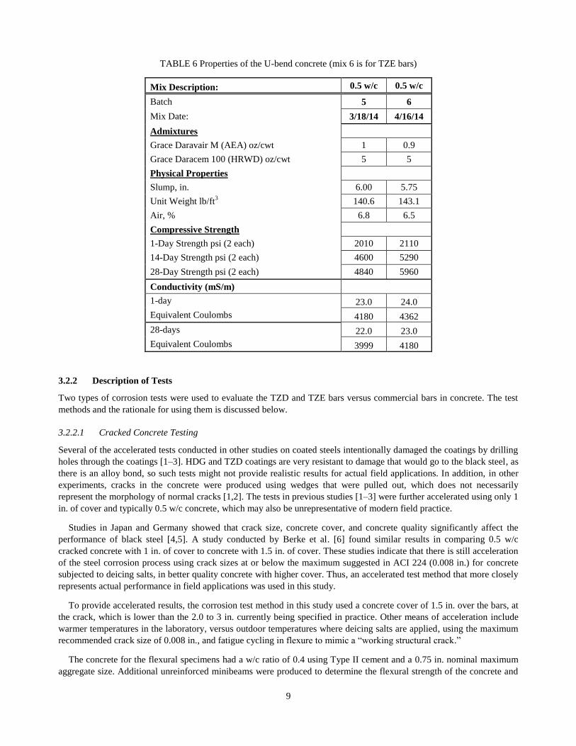
The concrete properties for the U-bend specimens are shown in Table 6. The test schedule for the TZE was delayed one
month due to the painting of the bars. The strengths were higher for the second mixture; however, both mixes had similar
permeability as seen in the conductivity data shown in Table 5. The conductivity data indicated that the mixes were on
the border between moderate and high permeability. This was expected as the w/c ratio was higher for these mixes than
that used for the beam specimens.

8
TABLE 4 Properties of the concrete produced for the cracked minibeams
Mix Description: 0.4 w/c
Batch 1 2 3 4
Mix Date: 3/11/14 3/11/14 3/12/14 4/15/14
Admixtures
Grace Daravair M (AEA) oz/cwt 1 1 1 1.2
Grace Daracem 100 (HRWD)
oz/cwt 7 7 7 7
Physical Properties
Slump, in. 6.00 4.75 4.75 4.75
Unit Weight lb/ft3 145.0 143.8 146.0 144.8
Air, % 6.5 7.3 5.5 5.9
Compressive Strength (C 39)
1-Day Strength psi (2 each) 2960 2300 2520 2910
14-Day Strength psi (2 each) 5810 5090 5560 5660
28-Day Strength psi (2 each) 6660 5460 6360 5960
Flexural Strength (C 78)
Minibeams
14-Day (psi) 850 725 735 775
28-Day (psi) 925 825 895 830
Cracking Stress of Reinforced C
78 Minibeams
Coated Rebar Specimens
TZD 14-Day (psi) 1170
ECR 14-Day (psi) 1000
HDG 14-Day (psi)
1150
TZE 14-Day (psi)
1075
Uncoated Rebar Specimens
BB 14-Day (psi)
1080
X35 14-Day (psi)
920
SS 14-Day (psi)
1080
TABLE 5 ASTM C1760 conductivity and equivalent
ASTM C1202 permeability for concrete used for minibeams
Conductivity
(mS/m)
Batch Number
1 2 3 4
14 days 18.0 25.8 15.0 16.2
Equivalent
Coulombs 3272 4689 2726 2945
28 days 16.6 17.8 14.7 16.1
Equivalent
Coulombs 3017 3235 2672 2926
9
TABLE 6 Properties of the U-bend concrete (mix 6 is for TZE bars)
Mix Description: 0.5 w/c 0.5 w/c
Batch 5 6
Mix Date: 3/18/14 4/16/14
Admixtures
Grace Daravair M (AEA) oz/cwt 1 0.9
Grace Daracem 100 (HRWD) oz/cwt 5 5
Physical Properties
Slump, in. 6.00 5.75
Unit Weight lb/ft3 140.6 143.1
Air, % 6.8 6.5
Compressive Strength
1-Day Strength psi (2 each) 2010 2110
14-Day Strength psi (2 each) 4600 5290
28-Day Strength psi (2 each) 4840 5960
Conductivity (mS/m)
1-day 23.0 24.0
Equivalent Coulombs 4180 4362
28-days 22.0 23.0
Equivalent Coulombs 3999 4180
3.2.2 Description of Tests
Two types of corrosion tests were used to evaluate the TZD and TZE bars versus commercial bars in concrete. The test
methods and the rationale for using them is discussed below.
3.2.2.1 Cracked Concrete Testing
Several of the accelerated tests conducted in other studies on coated steels intentionally damaged the coatings by drilling
holes through the coatings [1–3]. HDG and TZD coatings are very resistant to damage that would go to the black steel, as
there is an alloy bond, so such tests might not provide realistic results for actual field applications. In addition, in other
experiments, cracks in the concrete were produced using wedges that were pulled out, which does not necessarily
represent the morphology of normal cracks [1,2]. The tests in previous studies [1–3] were further accelerated using only 1
in. of cover and typically 0.5 w/c concrete, which may also be unrepresentative of modern field practice.
Studies in Japan and Germany showed that crack size, concrete cover, and concrete quality significantly affect the
performance of black steel [4,5]. A study conducted by Berke et al. [6] found similar results in comparing 0.5 w/c
cracked concrete with 1 in. of cover to concrete with 1.5 in. of cover. These studies indicate that there is still acceleration
of the steel corrosion process using crack sizes at or below the maximum suggested in ACI 224 (0.008 in.) for concrete
subjected to deicing salts, in better quality concrete with higher cover. Thus, an accelerated test method that more closely
represents actual performance in field applications was used in this study.
To provide accelerated results, the corrosion test method in this study used a concrete cover of 1.5 in. over the bars, at
the crack, which is lower than the 2.0 to 3 in. currently being specified in practice. Other means of acceleration include
warmer temperatures in the laboratory, versus outdoor temperatures where deicing salts are applied, using the maximum
recommended crack size of 0.008 in., and fatigue cycling in flexure to mimic a “working structural crack.”
The concrete for the flexural specimens had a w/c ratio of 0.4 using Type II cement and a 0.75 in. nominal maximum
aggregate size. Additional unreinforced minibeams were produced to determine the flexural strength of the concrete and

10
cylinders for compressive strength. Five reinforced flexural specimens were produced for each type of steel to account for
variability in corrosion testing.
The flexural specimens consisted of 20 × 6 × 6 in. concrete minibeams that have one bar on the top mat and two bars
to provide the cathode on the bottom mat. All bars were #4 deformed bars (0.5 in. in diameter) and were to be
preconditioned by rotation in a container of coarse aggregates, to simulate abrasion of the concrete aggregates during
field placement. A 1/8 in. deep notch was cut across the top in the center and the minibeams were third-point loaded to
generate a crack that was 0.008 to 0.01 in. wide. Minibeams were loaded and unloaded 5 times to 75 percent of the
flexural strength. After flexing, shims were inserted to keep the crack open and to apply a small stress to the bars. The
sides were sealed with epoxy and a dam (reservoir) was applied to the surface. Concrete cover over the bar at the bottom
of the notch was 1.5 in. Figure 3 is a schematic of the specimens.
The initial crack openings for the minibeams are in Table 7. The cracks did not go beyond the yield strength of the bars
(presumed to be the case as the cracks closed when the load was removed) so the bars were exerting a force to close the
cracks. Plastic shims were used to keep the cracks from closing. The cracks were in the range of 0.005 to 0.015 in. It is
difficult to control crack opening so the range is slightly larger than the desired range of 0.008 to 0.01 in., with one SS
and one HDG specimen having high values compared to other specimens, but still with low values for others.
FIGURE 3 Side view schematic of crack specimens with a dam on top and crack.
TABLE 7 Surface crack widths for the cracked minibeams specimens
Beams
Average Crack Width
(mils) for Group of Beams
Extreme Crack Widths
(mils) for Group of Beams
Avg. Std. Dev. High Low
BB 0.009 0.002 0.010 0.005
SS 0.013 0.005 0.020 0.007
X35 0.007 0.002 0.010 0.005
ECR 0.010 0.002 0.015 0.007
HDG 0.013 0.006 0.025 0.005
TZD 0.008 0.002 0.010 0.005
TZE 0.010 0.002 0.012 0.008

11
The specimens were ponded for one week with 3% NaCl and then dried for one week, and the cycle was repeated. The
current between the top and bottom bars measured by the voltage drop across a 10-ohm resistor, also called macro-cell
current, was to be measured at the end of the wet week as modified from the original proposal by the review committee.
The corrosion potential was measured using a copper/copper sulfate (Cu-CuSO4, or CSE) reference electrode (ASTM
C876). After the wet portion of every six cycles, the dams were removed, and the specimens were flexed five times to 75
percent using 4-point loading of the 28-day flexural strength for the specific concrete mixture for each beam. Dams were
reapplied and the testing continued with cyclic ponding.
Two specimens of five were removed for an autopsy at 34 cycles (68 weeks). The TZE specimens were removed at 36
weeks. The rest of the specimens remained in testing for 52 cycles (2 years) of testing. The autopsies included chloride
analysis at and away from the cracks, a corrosion evaluation of the bars (amount of rust and degree of rust), and
microscopy of the coated specimens.
3.2.2.2 Evaluation of Bent Bars Under Stress
Bars were bent in a U-bend as in ASTM G 30 Standard Practice for Making and Using U-Bend Stress-Corrosion Test
Specimens. Figure 4 shows a schematic of the specimens that consisted of a bar with a U-bend, placed in a rectangular
concrete block. The concrete cover over the reinforcement was only 1.0 in. to accelerate the ingress of chloride and a
concrete with a w/c = 0.5 was used to further accelerate testing because of relatively higher porosity. A higher w/c
concrete is being used here to decrease the time for chloride ingress, since these specimens were uncracked. The bend
was a 5-d diameter, without over-bending, so the ends were pulled in keeping the bars under stress. After bending the
bars, micrographs, and photos of the bent area were taken to document the condition before corrosion testing.
The HDG coatings on reinforcing bars could crack in bending so mandrel diameters are typically 6-d or larger
according to ASTM A767. ASTM A615 allows mandrel diameters to 3.5-d for bars up to Grade 60 and 5-d for bars up to
Grade 80. The larger mandrel diameters for bending galvanized bars are to lessen the cracking damage caused by bending
of the coating, which could adversely affect corrosion resistance. ECR can use the same bending diameters as HDG bar,
but some crazing of the coating might occur.
The bars were not bent beyond 180 degrees and released to reduce stress, so the holder on the top of the specimens in
Figure 6 was used to keep the bars vertical in the specimens. The X35 bar had a stress in excess of 90,000 psi because it
does not have a typical yield point and it was not over-bent and released. This is far beyond what would be used in the
field and was not realized to be the case at the time.
FIGURE 4 Schematic of 9-in. tall (concrete portion) U-bend specimens. Specimens were 7-in. wide for 2.5 in.
diameter bends, and 8-in. wide for 3.0-in. diameter bends.
The appearance of the coated bars after bending is shown in Figure 5. The TZE coating did not have good adhesion at
the bends as it was applied manually and was not optimized for this application. The TZD, HDG and ECR coatings
looked good.

12
The U-bend specimens were partially ponded in 4.5-in. of 3% by weight NaCl solution in water (half the concrete
specimen height). Corrosion potentials were measured on a monthly basis. Polarization resistance and electrochemical
impedance spectroscopy (EIS) were performed initially after 1 month, and then at three month intervals or when
corrosion was indicated in the corrosion potential tests. Specimens were removed for an autopsy at 17 months (two of
five specimens) and at two years.
FIGURE 5 Coated bars after bending: (a) TZD; (b) HDG; (c) TZE; (d) ECR. Only TZE bar showed severe cracks
and defects in both the tension and compression sides of the bend.
3.3 RESULTS AND DISCUSSIONS
3.3.1 Cracked Minibeams
3.3.1.1 Electrochemical Corrosion Tests
Corrosion potentials, macrocell corrosion currents between the top and bottom bars, chloride distributions, a percentage
of rust and mass loss tests were conducted. The tests ended after 52 cycles (two weeks/cycle). Two of the five specimens
were removed before the end of the testing for a preliminary analysis at 34 cycles (36 for TZE). A picture of the
minibeams is shown in Figure 8.
Table 8 provides the average corrosion potential data for the minibeams over time, and Tables 9 and 10 provide the
average macrocell currents. The difference between Table 9 and Table 10 is that some specimens had reverse macrocells
(top bar acting as a cathode to the bottom bar), so Table 10 shows the absolute value of the measured macrocell current.

13
FIGURE 6 Cracked beam corrosion specimens. Specimens are 6 in. x 6 in x 20 in.
TABLE 8 Average corrosion potentials versus time for the cracked minibeams

14
For uncoated steel reinforcement, corrosion potentials more negative than −350 mV vs. CSE are typically related to
the breakdown of passivity. According to ASTM C876, corrosion potentials lower than −350 mV CSE indicate a 90
percent probability of corrosion occurring at the time of measurement. All of the BB specimens clearly went into
corrosion on the first cycle and this is reflected in the average corrosion potentials in Table 8 and the macrocell currents
in Tables 9 and 10. Note that based upon the exposed area of the top bar, a macrocell current of 10 µA is equivalent to
0.1 µA/cm2, and the initiation of corrosion. The comparison of the average corrosion potentials to the average macrocell
current is not as straightforward for the other specimens.
TABLE 9 Average macrocell data versus time for the cracked minibeams
Figure 9 shows a plot of the average integrated macrocell currents including the currents on all the bars. All of the
corrosion-resistant reinforcing bars outperformed BB. The slope of the curves is the macrocell corrosion rate and it shows
a decrease for the BB after 200 days. This can be attributed to re-passivation of the BB, corrosion products reducing the
rate of corrosion, or to corrosion of the bottom bars that would reduce the cathode area available for macrocell corrosion.
As will be shown later, the corrosion of the bottom bars is the most likely cause for this behavior.
The HDG and TZD showed high initial corrosion rates as indicated in Tables 9 and 10 and Figure 7. This is due to the
zinc coating developing a protective oxide. The TZD is a more porous coating, so the current would be higher than for
the HDG as more surface area is present. Since a macrocell was present it indicates that the zinc coatings passivate
quicker in the absence of chloride. Once the oxide was formed the corrosion rates became equivalent to that of SS until
the severe corrosion reinitiated due to higher chloride values. There was a period of low corrosion until the zinc coatings
were penetrated. The TZD coating was less than half the thickness of the HDG coating so it would be expected to behave
as shown.
The ECR, SS, HDG and TZE bars showed the least macrocell current. This would be expected for ECR and TZE as
coated steel will do well in a short time test of this nature. However, as will be shown in later sections, corrosion did

15
occur on both TZE and ECR. The increase in total corrosion current was 48% for ECR, 41.7% for SS, and 73.1% for
HDG, comparing values in Table 10 with Table 9.
TABLE 10 Average macrocell data versus time for the cracked minibeams
including macrocell current on the bottom bars
FIGURE 7 Total integrated macrocell current over time.
2 specimens removed

16
The variation in the data is shown in Figures 8–15, which give the corrosion potentials, macrocell currents, and
integrated macrocell currents for each series of bars. As noted, two minibeams of each bar type were removed for autopsy
at 34 cycles; therefore, three minibeams were tested for the entire 52 cycles (2 years).
A rule of thumb is that cracking due to corrosion could occur at approximately 1 mil (0.001 in.) of bar loss, which
corresponds to 68.4 Coulombs/cm2 or 6900 Coulombs [11,12]. The macrocell corrosion only reached half that value for
some of the black bar specimens. The corrosion potential data has little scatter but there is more scatter in the current
data, which can vary by over an order of magnitude in corrosion testing, which is one reason for testing five specimens.
FIGURE 8 Macrocell data for BB cracked minibeams.
Figure 9 provides the macrocell data for the TZD cracked minibeams. Only two of the five minibeams had severe
macrocell corrosion, which initiated at a later point than seen for all the BB specimens corroding. As noted earlier, scatter
in corrosion data are expected once specimens start to corrode. The initial corrosion potentials start negative as the zinc is

17
passivating. When the current decreased to passive levels the corrosion potentials were in the range of passive steel in
concrete. This might be due to the nature of the coating, which is a zinc-iron intermetallic and not pure zinc. When
corrosion did initiate there was a sharp decrease in potential to those associated with corrosion of black bar and as seen
on the BB specimens. This is a good means to monitor performance, which as will be shown is not the case for HDG.
FIGURE 9 Macrocell data for TZD cracked minibeams.
The macrocell corrosion rates for the three TZD passive bars were very similar to those of SS bars as will be shown
later. Though the corrosion rate for corroding bars appeared to be higher than that for some BB bars, this is due to the
bottom bars providing more of the cathode as their corrosion rate is low.

18
Figure 10 shows the corrosion behavior for the HDG minibeams. Scatter in corrosion data is not unexpected, and could
be due to differences in chloride contents in the individual specimens, and local variations in the concrete. Even the two
corroding TZD specimens outperformed the best control specimens.
FIGURE 10 Macrocell data for HDG cracked minibeams.
The corrosion performance of HDG initially was similar to TZD, which indicated high currents and low negative
potentials. However, the zinc coating passivated potentials did not become more positive than −350 mV vs. CSE, so
there is not a set potential above which passivation is indicated, as was the case for TZD. The macrocell current behavior
indicates better performance than the TZD. Some of this would be due to a higher coating thickness, and as will be shown
later and can be seen in comparing total Coulombs in Table 9 with Table 10, there was considerable macrocell corrosion
rates on the bottom bars indicating that the macrocell currents are not indicative of all of the corrosion.

19
The addition of a non-optimal hand-painted, epoxy coating to the TZD considerably reduced macrocell current as seen
in Tables 9 and 10 and Figure 7. Figure 11 provides the macrocell data for the individual specimens. The current axis and
integrated current axis are on a different scale than that used for the BB, TZD, and HDG specimens, in Figure 11, to
reflect the much lower currents for TZE.
FIGURE 11 Macrocell data for TZE cracked minibeams.
It is difficult to find a relationship between corrosion potential and the macrocell corrosion for the TZE bars, most
likely due to the organic coating present. The specimen with the lowest current (TZE 4) did, however, have a corrosion
potential more positive than −300 mV CSE. The overall macrocell currents are very low indicating that it would take
several years of accelerated corrosion testing to cause damage to the concrete if the corrosion rate remained in this range.
As in any product with a nonconductive barrier coating, such as the ECR specimens in this study, the corrosion currents
are primarily concentrated at the flaws, so corrosion rates are higher at those locations.

20
The ECR individual specimen macrocell data are in Figure 12. The test method is not as severe to these bars as the
other bars, as coating failure mechanisms are often due to aging effects of the coating, which takes several years to occur.
Also, as the ECR bars have specification requirements for the coating system, including limits on allowable defects, they
were less damaged by the pretreatment techniques than the TZE bars. As such the currents and integrated currents for the
ECR bars as shown in Figure 12 are very low, even lower than what was observed for the SS bars as can be seen in
Tables 9 and 10.
FIGURE 12 Macrocell data for ECR cracked minibeams.
The ECR minibeams as noted had very low macrocell corrosion, but it was not zero, indicating that some current is
generated at locations of coating through defects. The corrosion potential data showed initially high negative potentials
that then came into the range where BB is considered to be passive. This indicates that oxygen and liquid are passing
through the coating, but not chloride. A large decrease of potential for two of the specimens occurred after about a year of
testing. This indicates that some corrosion might be occurring, but not being identified in the macrocell data. This will be
addressed when the autopsy results are discussed.

21
The other two commercial alloys tested were the X35 and SS bars. Figure 13 provides the macrocell data for the X35
specimens. Corrosion initiation occurred between 105 and 357 days, which was a considerable improvement over the BB
specimens. Comparing the corrosion potentials to when the macrocell current was approximately 10 µA or lower
indicates that the potential below which the bars are active in this set of experiments is approximately −280 mV vs. CSE.
The higher value than for BB might be due to the chromium content in the passive oxide that forms on the X35 bars.
FIGURE 13 Macrocell data for X35 cracked minibeams.
The results for the X35-2 specimen as shown in Figure 13 indicate that the bar re-passivated as the current decreased
and the corrosion potential moved to the passive region. Since there were no reverse macrocells, this indicates that the bar
is passivating, perhaps due to surface enrichment in chromium as the iron corrodes. Similar behavior was found for X35-
3 before it was removed.

22
The SS specimen macrocell data are shown in Figure 14. The macrocell corrosion rates were low and the half-cell
potentials were in the passive region for all the specimens. However, there were a few times when the currents jumped
indicating that some corrosion might have initiated then re-passivated. Only at 301 days did the currents exceed 10 µA.
FIGURE 14 Macrocell data for SS cracked minibeams.

23
3.3.1.2 Appearance and Autopsy Results
3.3.1.2.1 Cracks
In the process of testing, some cracking occurred on some of the cracked minibeams. Table 11 shows a synopsis of the
cracking data. These cracks formed within the first year of testing and did not change after that. Figure 15 shows one of
the most severe cracks that formed on an HDG specimen.
TABLE 11 Crack summary on minibeams after one year of testing including
fatigue for five minibeams total of each bar type.
FIGURE 15 Crack on one of four HDG minibeams that cracked in testing.
The best performing bars are the X35, TZD, SS, and TZE. As shown in Table 11 cracking was more severe on the
HDG and BB. The longest crack lengths were for ECR. None of the specimens had rust staining or cracking at the
surface. Given the earlier discussion about the amount of integrated current, this is as would be expected.
3.3.1.2.2 Autopsy results
Two minibeams of five were removed after 34 cycles (36 cycles for TZE), for an autopsy. Table 12 shows the acid
soluble chloride content, based on mass of the concrete, at the top and bottom reinforcing bar level at and away from the
crack. The chloride contents were not determined for all the specimens as they were similar to other mixes. The
macrocell current at the time of removal and the integrated macrocell current data are included. Note that the chloride
levels at the lower bar level under the crack are lower for the TZD and X35 specimens, which will be addressed in detail
when the chloride analyses at the end of testing are discussed.
BB ECR X35 SS HDG TZD TZE
No. Cracked 3 2 1 1* 4 2 0
No. >0.004 in. 0 1 0 0 2 0 0
Length (in.)
Crack 1 2 4 CI 3 CI
Crack 2 CI 4 2 (CI) < 2*
Crack 3 2 2
Crack 4 2 (CI)
CI =Chipped at insert
*Crack is perpendicular to bar

24
Figure 16 shows the corrosion of the BB-2 specimen at 34 cycles. As both BB specimens had similar behavior only
one is shown. There is some corrosion on the bottom bar that would account for the macrocell current decreasing in time
as the bottom bar was both an anode and a cathode. The BB corroded in the first cycle so the chloride contents are well
beyond the point of when corrosion initiated and much higher than the 500 to 600 ppm on concrete typically used for
black bar.
TABLE 12 Acid soluble chloride contents (on concrete) and corrosion data at 34 cycles (36 for TZE)
FIGURE 16 BB-2 bars after 34 cycles (68 weeks) of corrosion testing.
Figure 17 shows the TZD bars after removal at 34 cycles. One bar with a high macrocell current and high integrated
current, TZD-4, shows corrosion damage. The bars in specimen TZD-5 had lower current and did not have red rust. No
SpecimenPotential (mV,
CSE)
Absolute Current
(µA/cm2)Coulombs Bar
Chloride Value
(crack)(ppm)
Chloride Value
(offset) (ppm)
Top 2582 662
Bottom 1247 493
Top 2212 620
Bottom 1085 732
Top
Bottom
Top 2385 613
Bottom 1676 571
Top 2070 669
Bottom 1335 562
Top 2613 704
Bottom 1548 587
Top 2530 701
Bottom 1478 692
Top 1944 939
Bottom 686 497
Top 2521 766
Bottom 1611 510
Top 2530 800
Bottom 1458 746
Top 2778 779
Bottom 1671 722
Top
Bottom
Top 2653 690
Bottom 1668 728
Top
Bottom
X35 - 5 -352 0.754 2930
X35 - 3 -210 0.081 492
SS - 5 -194 0.002 53
SS - 1 -183 0.002 57
TZE - 5 -290 0.049 77
TZE - 1 -371 0.160 190
TZD - 5 -204 0.023 586
TZD - 4 -391 2.374 1568
EC - 5 -70 0.002 27
EC - 1 -72 0.009 25
HDG - 4 -619 0.049 1139
HDG - 2 -450 0.024 372
BB - 5 -404 0.783 3432
BB - 2 -408 0.523 3336

25
red rust corrosion is evident on the bottom bars; however, about 2% white corrosion product is on one bottom bar.
Chloride values at the reinforcing bar levels indicate that the acid soluble corrosion threshold for severe corrosion occurs
between 1,400 and 2,500 ppm chloride based on mass of the concrete.
FIGURE 17 TZD bars after 34 cycles (68 weeks) of corrosion testing.
Figure 18 shows the HDG bars at 34 cycles. Though the corrosion macrocell currents were low on the HDG-2 bars
there is evidence of white corrosion products on both the top and bottom bars and some rust spots on the top bar. The
HDG-4 top bar has a deep pit and both bars show white corrosion products, typical of corroding zinc.
FIGURE 18 HDG bars after 34 cycles (68 weeks) of corrosion testing.

26
The chloride data in Table 12 indicate that the corrosion threshold would be under 2,500 ppm of chloride by mass of
concrete. However, since corrosion occurred at lower macrocell activity this value is most likely lower, and bottom bar
corrosion indicates that the threshold is less than 1,600 ppm of chloride. Analysis of chloride threshold for TZD and
HDG is complicated by the pre-passivation high corrosion rate followed by a slow passive rate. Both bars far surpassed
the performance of the BB, which had corrosion on the top and bottom bars and initiated corrosion early.
Figure 19 shows the X35 bars removed at 34 cycles. There was some corrosion on the bottom bars, but this is
indicative of the original condition of some of the bars after wire brushing off rust in the as-received condition (see
Appendix), the bottom bars at 52 cycles showed no rust. The chloride levels at the bottom bars were over 1,335 ppm and
the top bars were over 2,200 ppm, indicating that the chloride threshold is over 1,400 ppm but less than 2,200 ppm.
FIGURE 19 X35 bars after 34 cycles (68 weeks) of corrosion testing.
Figure 20 shows the ECR and SS bars. There no sign of corrosion on the ECR at that time. The SS bar had one rust
stain (arrow) but otherwise was in excellent condition. Concrete did not stick to either of these steels, unlike the case for
the other bars.
The chloride data would indicate that the chloride threshold value is greater than 2,400 ppm by mass of concrete for
the SS bar. Since there were no coating defects on the ECR, it performed well in the accelerated testing up to 34 cycles.
Rapid ingress of chlorides might not provide sufficient time for organic coating failure processes to occur so it is difficult
to determine a chloride corrosion threshold.
The TZE bars after 36 cycles are shown in Figures 21 and 22. The hand-painted coating had poor adhesion and rubbed
off during the fabrication of the minibeams. Since there is slightly more damage in the middle of the bars, the fatigue
cycling might have caused some of the damage. Even with the coating compromised, there was only slight rust staining
on the top bar in Specimen 1. The visual performance was better than BB and TZD and HDG even with the poor coating.

27
FIGURE 20 ECR and SS bars after 34 cycles (68 weeks) of corrosion testing.
Arrow shows staining on SS bar.
FIGURE 21 TZE-1 bars after 36 cycles (72 weeks) of corrosion testing.

28
FIGURE 22 TZE-4 bars after 36 cycles (72 weeks) of corrosion testing.
At the end of testing, 52 cycles (104 weeks), complete autopsies were completed on the remaining groups of
specimens. Table 13 shows the average chloride profiles at and away from the cracks and at the bottom bars. A statistical
analysis (n = 3) showed that at an 80% Confidence Limit, there was a reduction of mean chloride concentration at the
bottom rebar level under the crack for the TZD versus BB minibeams with a confidence limit of +150 ppm by mass of
concrete.
TABLE 13 Average acid soluble chloride (on concrete) profiles for specimens removed
after 52 cycles (two years) of testing
0 to 1/2 1/2 to 1 1 to 1-1/2 1-1/2 to 2 2 to 2-1/2
1- Top Center Crack 5662 4052 3226 2976 2251
2- Top Offset 4039 1778 639 891 650
3- Bottom Center Crack 1600
4- Bottom Offset 901
1- Top Center Crack 6394 4010 3574 2861 3058
2- Top Offset 3944 1648 828 735 700
3- Bottom Center Crack 1635
4- Bottom Offset 652
1- Top Center Crack 6312 4364 3326 2823 2580
2- Top Offset 4214 1802 771 688 824
3- Bottom Center Crack 1296
4- Bottom Offset 668
1- Top Center Crack 5434 3586 2940 2709 2232
2- Top Offset 3646 1479 841 688 767
3- Bottom Center Crack 1498
4- Bottom Offset 688
1- Top Center Crack 6389 3946 3295 2825 2567
2- Top Offset 3669 1787 869 815 800
3- Bottom Center Crack 1565
4- Bottom Offset 798
1- Top Center Crack 5844 3872 3139 2721 2523
2- Top Offset 2913 1500 830 777 791
3- Bottom Center Crack 1793
4- Bottom Offset 637
1- Top Center Crack 5818 3751 3305 2890 2687
2- Top Offset 3907 1669 720 621 650
3- Bottom Center Crack 1840
4- Bottom Offset 776
SS
TZE
Beam
RebarSample Location
Depth Increments in Inches
BB
HDG
TZD
X-35
EC

29
As expected, the chloride levels at the cracks were considerably higher than away from the cracks in the top 2.5 in. of
the specimens. The increase in chloride 5 in. from the surface under the crack (as indicated by comparing “Bottom Center
Crack” with “Bottom Offset” values in Table 13) was unexpected and indicates that surface crack could potentially affect
bottom mat reinforcing bars.
The chloride levels at 52 cycles were higher than at 34–36 cycles as expected. Only the SS bars had no corrosion at 52
cycles so their chloride threshold value in this test would be over 2,700 ppm by mass of concrete or 10.7 pcy. The value
for the X35 remains at 7.9 pcy as found at 34 cycles. The X35 most likely would have had better performance if it had a
cleaner initial surface. The TZD and HDG bars would still have a range of performance as it is not as clear as to when
they started to corrode. This is especially true for the HDG bars. All bars outperformed the BB.
Analysis of the bars at the completion of testing adds considerably more information. Photographic, metallography,
and mass loss tests were performed to compare the corrosion of the bars to the macrocell measurements. This is useful in
determining if the macrocell data did not account for all of the corrosion (due to microcells and bottom bar corrosion) and
to see how the bars perform after corrosion initiated.
Figures 23–29 show representative bars after 52 cycles at the completion of the corrosion testing. The top bar
designated 1 and the two bottom mat bars designated as 2 and 3 are shown. The summary of the corrosion damage for the
bars at 34 (36 cycles TZE) and 52 cycles is shown in Table 14. Table 15 shows the statistical analysis of the results when
the percentage of rust based on surface area is multiplied by the degree of rust. Most weight is given to pitting corrosion
where the corrosion was on the order of or higher than the rib height. The visual rating system is shown in Figure 30.
FIGURE 23 BB-3 bars after 52 cycles. Bar 1 is the top bar and bars 2 and 3 are the bottom mat bars.

30
FIGURE 24 TZD-2 bars after 52 cycles. Bar 1 is the top bar and bars 2 and 3 are the bottom mat bars.
FIGURE 25 HDG-3 bars after 52 cycles. Bar 1 is the top bar and bars 2 and 3 are the bottom mat bars.

31
FIGURE 26 TZE-2 bars after 52 cycles. Bar 1 is the top bar and bar 2 is a bottom mat bar.
FIGURE 27 ECR-4 bars after 52 cycles. Bar 1 on top and magnified or the top bar, bar 2 is a bottom mat bar.
FIGURE 28 X35-1 bars after 52 weeks of corrosion. Bar 1 is the top bar and bars 2 and 3 are the bottom mat bars.

32
FIGURE 29 SS-3 bars after 52 cycles. Bar 1 is the top bar and bar 2 is a bottom mat bar.
FIGURE 30 Visual rating system for corrosion performance used in Tables 14 and 15.

33
TABLE 14 Summary of visual corrosion damage and integrated macrocell current
at 34 and 52 cycles (1 cycle = 2 weeks)
Note: White rust is applicable to zinc coated bars only.
Bar 1 Bar 2 Bar 3 Bar 1 Bar 2 Bar 3 Bar 1 Bar 2 Bar 3
1 52 4 3 3 P M M 2523
2 34 3 3 3 P M M-H 3336
3 52 4 3 3 P M M 2182
4 52 4 3 0 H-P L-M 0 3495
5 34 4 3 3 P M H 3432
1 52 5 1 2 4 1 2 L L L 4523
2 34 3 0 0 3 3 4 M L L 112
3 52 3 3 2 3 3 2 H-P L L 576
4 34 3 2 0 5 4 5 M L L 1139
5 52 4 4 3 4 3 2 H L L 276
1 36 3 2 0 L L - 186
2 52 4 1 0 M L - 210
3 52 3 1 0 M L - 154
4 52 2 0 0 L - - 101
5 36 3 0 0 L - - 76
1 52 3 0 0 3 3 3 M L L 4174
2 52 3 0 0 3 0 2 L - L 859
3 52 1 0 0 4 0 4 L - L 771
4 34 3 0 0 3 0 2 M - - 1568
5 34 0 0 0 1 0 0 L - - 585
1 52 3 2 0 L-M L - 2428
2 52 3 0 0 L-M - - 1657
3 34 3 4 4 H L L 492
4 52 4 1 0 M-H L - 2407
5 34 3 4 4 H L L 2930
1 34 0 0 0 - - - 46
2 52 0 0 0 - - - 49
3 52 0 0 0 - - - 50
4 52 0 0 0 - - - 44
5 34 0 0 0 - - - 29
1 34 0 0 0 - - - 20
2 52 1 0 0 L - - 26
3 52 0 0 0 - - - 22
4 52 2 0 1 L - L 34
5 34 0 0 0 - - - 14
P=Pitting and loss of steel
X35
SS
ECR
L=Light corrosion product
M=Moderate corrosion product
H=High corrosion product
Coulombs
at Removal
BB
HDG
TZE
TZD
Bar Beam #Cycles at
Removal
% Red Rust % White Rust Corrosion Severity
34
TABLE 15 Statistical analysis of data in Table 14. Corrosion damage is % red rust *severity
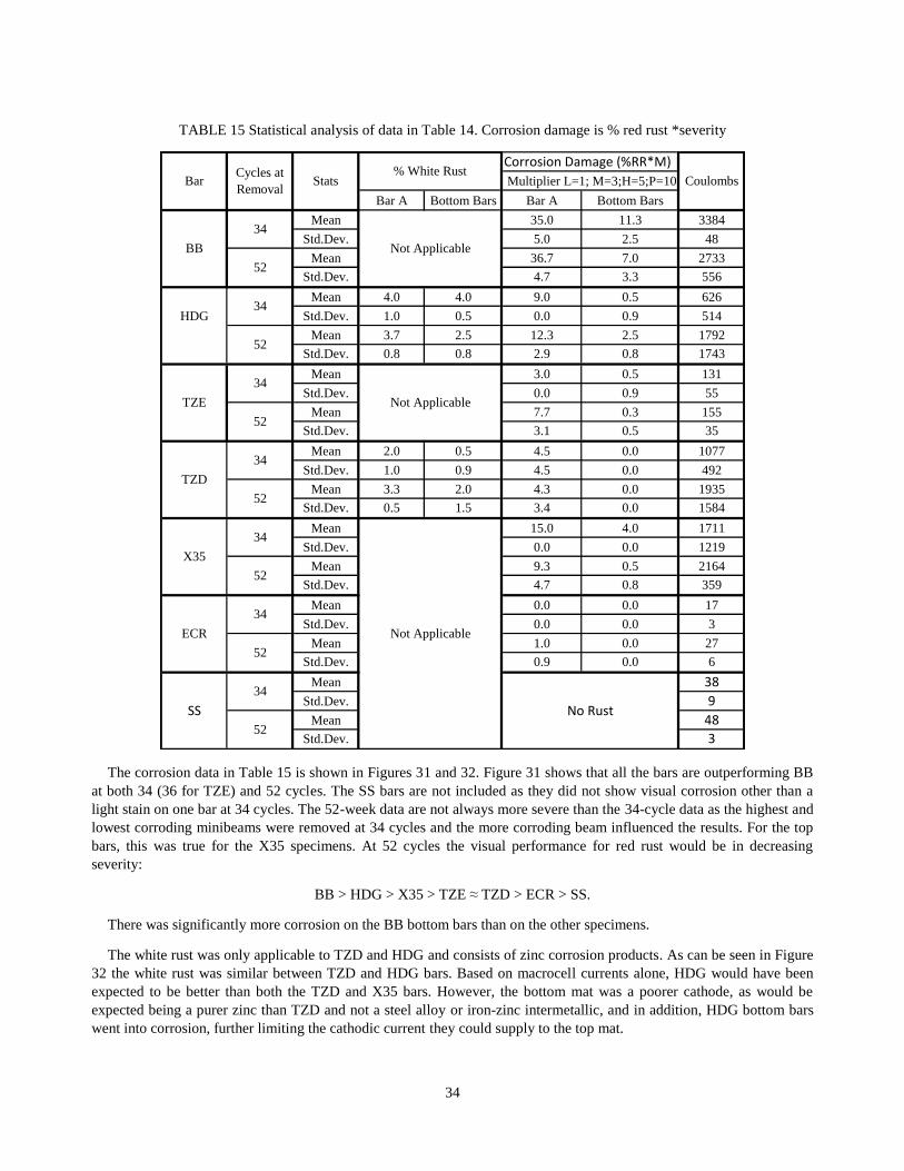
The corrosion data in Table 15 is shown in Figures 31 and 32. Figure 31 shows that all the bars are outperforming BB
at both 34 (36 for TZE) and 52 cycles. The SS bars are not included as they did not show visual corrosion other than a
light stain on one bar at 34 cycles. The 52-week data are not always more severe than the 34-cycle data as the highest and
lowest corroding minibeams were removed at 34 cycles and the more corroding beam influenced the results. For the top
bars, this was true for the X35 specimens. At 52 cycles the visual performance for red rust would be in decreasing
severity:
BB > HDG > X35 > TZE ≈ TZD > ECR > SS.
There was significantly more corrosion on the BB bottom bars than on the other specimens.
The white rust was only applicable to TZD and HDG and consists of zinc corrosion products. As can be seen in Figure
32 the white rust was similar between TZD and HDG bars. Based on macrocell currents alone, HDG would have been
expected to be better than both the TZD and X35 bars. However, the bottom mat was a poorer cathode, as would be
expected being a purer zinc than TZD and not a steel alloy or iron-zinc intermetallic, and in addition, HDG bottom bars
went into corrosion, further limiting the cathodic current they could supply to the top mat.
Corrosion Damage (%RR*M)
Bar A Bottom Bars Bar A Bottom Bars
Mean 35.0 11.3 3384
Std.Dev. 5.0 2.5 48
Mean 36.7 7.0 2733
Std.Dev. 4.7 3.3 556
Mean 4.0 4.0 9.0 0.5 626
HDG Std.Dev. 1.0 0.5 0.0 0.9 514
Mean 3.7 2.5 12.3 2.5 1792
Std.Dev. 0.8 0.8 2.9 0.8 1743
Mean 3.0 0.5 131
Std.Dev. 0.0 0.9 55
Mean 7.7 0.3 155
Std.Dev. 3.1 0.5 35
Mean 2.0 0.5 4.5 0.0 1077
Std.Dev. 1.0 0.9 4.5 0.0 492
Mean 3.3 2.0 4.3 0.0 1935
Std.Dev. 0.5 1.5 3.4 0.0 1584
Mean 15.0 4.0 1711
Std.Dev. 0.0 0.0 1219
Mean 9.3 0.5 2164
Std.Dev. 4.7 0.8 359
Mean 0.0 0.0 17
Std.Dev. 0.0 0.0 3
Mean 1.0 0.0 27
Std.Dev. 0.9 0.0 6
Mean 38
Std.Dev. 9
Mean 48
Std.Dev. 3
Coulombs
Not Applicable
Not Applicable
Not Applicable
No Rust
TZE
Multiplier L=1; M=3;H=5;P=10Cycles at
RemovalBar Stats
ECR
34
52
34
52
SS
34
52
34
52
34
52
34
52
34
52
TZD
BB
X35
% White Rust

35
FIGURE 31 Corrosion of reinforcing bars at the completion of testing. SS bars had no visual rust.
FIGURE 32 White rust on TZD and HDG bars at the completion of testing.
The last series of tests was mass loss conducted on sections of some bars after removal and comparing it with the
initial masses per unit length of non-corroded bars. This testing was performed for the uncoated bars and the TZD and
HDG bars.
0
5
10
15
20
25
30
35
40
BBTop34
BBBot34
BBTop52
BBBot52
HDGTop34
HDGBot34
HDGTop52
HDGBot52
TZETop36
TZEBot36
TZETop52
TZEBot52
TZDTop34
TZDBot34
TZDTop52
TZDBot52
X35Top34
X35Bot34
X35Top52
X35Bot52
ECRTop52
ECRBot
Co
rro
sio
n D
amag
e (%
Re
d R
ust
* S
ever
ity)
Rebar Type, Location, Cycles at Removal
Corrosion Damage
0
0.5
1
1.5
2
2.5
3
3.5
4
4.5
HDG
Top 34
HDG
Bot 34
HDG
Top 52
HDG
B0t 52
TZD
Top 34
TZD B1
34
TZD
Top 52
TZD B1
52
% W
hit
e R
ust
Rebar Type, Location, Cycles at Removal
White Rust

36
Removing the epoxy coatings without damaging the substrate would require hazardous organic solvents, so it was not
performed, given the negligible corrosion on these bars. Bars were cleaned with a bristle brush before chemically
stripping the corrosion products using concentrated acid solution stipulated in ASTM G1. BB was cleaned with solution
C.3.5 [500 mL hydrochloric acid (HCl, sp. Gr. 1.19) 3.5 g hexamethylene tetramine, Reagent water to make 1000 mL],
SS and X35 were cleaned with solution C.7.1. (100 mL nitric acid (HNO3, sp. Gr. 1.42), Reagent water to make 1000
mL) Initial coating thickness for TZD and HDG were determined by dissolving the zinc coatings in C.3.5. After
completion of testing, the corrosion products were removed from the TZD and HDG coatings using solution C.9.5 [100 g
ammonium persulfate ((NH4)2S2O8), Reagent water to make 1000 mL] and then the remaining zinc was determined by
dissolving it off in the C.3.5 solution.
Table 16 has the calculated bar or coating loss for selected specimens. Also included is the total macrocell current
divided by the entire area of the bar and then the calculated thickness loss based on Faraday’s equation, shown below,
relating mass loss to charge passed per unit area and dividing by the density to determine a thickness loss.
𝑊 =
𝐼 ∗ 𝑡 ∗ 𝐴
𝑛 ∗ 𝐹
Where W is the weight of the plated metal in grams,
I is the current in coulombs per second,
t is the time in seconds,
A is the atomic weight of the metal in grams per mole,
n is the valence of the dissolved metal in solution in equivalents per mole,
F is the Faraday’s constant
TABLE 16 Measured thickness losses and calculated average thickness loss (mils)
based on the macrocell current/bar area
The average thickness loss from the macrocell data is less than that measured in regions of high corrosion. This is to be
expected as the corroding areas would have had higher current densities and only represent a small portion of the total
area as seen in Table 14. The microcell corrosion could be appreciable [7] especially in the case of the HDG bars that
showed reverse macrocells. Macrocell current is still a good indicator of corrosion activity but needs to be augmented
with additional analyses as performed in this work. Based on macrocell alone times to corrosion induced cracking would
be based on the total macrocell mils divided into 1 mil times 2 years; for example, about 5.5 years for the BB-1 specimen,
assuming the average corrosion rate did not change.
3.3.2 U-Bends
Corrosion potential, polarization resistance (corrosion rate), electrochemical impedance spectroscopy (EIS, corrosion,
resistivity), appearance, and chloride distributions were measured over a two-year period. Two of five specimens were
removed at 68 weeks unless otherwise noted. The EIS was mainly used to determine the concrete resistivity between the
reference electrode and the bar so that the polarization resistance could be corrected for the voltage drop due to passing
current through a resistive medium (concrete), known as IR drop. This needed to be used as the U-bend configuration
made it difficult for the potentiostat to correct for this automatically. The two methods have been shown to provide equal
results [8].
Total Macrocell Total Macrocell
Near Rust* No Rust White Rust Near Rust No Rust White Rust C/cm2
mils
BB-1 2.98 0.00 2.22 0.47 24.90 0.36
TZD-2 1.61 0.16 1.55 1.79 1.81 8.48 0.14
HDG-5 1.58 2.15 1.33 1.03 1.23 0.32 2.72 0.05
X35-1 1.29 0.00 0.32 0.19 23.97 0.35
SS-1 0.00 0.00 0.00 0.00 0.45 0.01
*Rust for uncoated bars, coating loss near rust location for coated bars.
Top Bar Bottom BarRebar-Beam

37
Figure 33 shows the average corrosion potentials versus the saturated Calomel (SCE) reference electrode. ASTM G3
notes that the values would be approximately 60 mV more negative if a saturated Cu/CuSO4 (CSE) was used. The HDG
specimens seemed to have a less negative potential than found in the cracked minibeams and less negative than would be
expected. There was a fair amount of variability that was presumably due to the low concrete cover and higher w/c for the
concrete.
Figure 34 shows the average corrosion damage as the integration of the inverse of the polarization resistance, 1/Rp
versus time. Initially, all of the specimens outperformed the BB but by 1 year the TZD specimens started to show high
corrosion rates. The X35, HDG, and TZE continued to show an improvement, and the ECR and SS specimens showed
the least corrosion behavior.
FIGURE 33 Average corrosion potentials versus time for U-bend specimens.
FIGURE 34 Total average corrosion versus time as measured by the integration of 1/Rp.

38
The corrosion potentials for TZE and X35 became more negative as the corrosion started to decrease; this will be more
clearly seen in the following graphs of the individual specimens.
Figure 35 shows the individual BB control specimens. The initial corrosion rate decreased until severe corrosion
initiated, as seen in a large drop in potentials and an increase in 1/Rp; a calculated corrosion rate can be determined
assuming a constant of 26 mV to multiply 1/Rp. Assuming that 1 mil of average corrosion is needed to crack concrete the
value would be approximately 68 C/cm2 of integrated current [9]. The corrosion data are close to that value.
As can be seen in Figure 35, the corrosion rate (1/Rp) and corrosion current (Icorr) curves mimic each other, since
they are related by a common (assumed) factor. Subsequent graphs will only show the 1/Rp data. This eliminates
assumptions about the constants used to convert the data to currents.
Figures 36 and 37 show the U-bend data for the TZD as compared to X35 specimens. There is much more scatter in
the TZD specimens. In contrast to the cracked beam data the TZD is not showing improvements over BB. The 1/Rp value
at 686 days appears to be an anomaly. The X35 specimens are outperforming the BB specimens. Both show that a drop in
corrosion potential correlates to a rise in corrosion activity.
FIGURE 35 U-bend corrosion data over time for the BB specimens.
-1000
-800
-600
-400
-200
0
200
0 100 200 300 400 500 600 700 800
Pote
nti
al (
mV
vs.
Ag/A
gC
l )
Time (days)
Corrosion Potential Ecorr vs. Time
BB-16
BB-17
BB-18
BB-19
BB-20
0
50
100
150
200
250
0 100 200 300 400 500 600 700 800
1/R
p (
µS
/cm
2)
Time (days)
Corrosion Rate 1/Rp vs. Time
0
1000
2000
3000
4000
0 100 200 300 400 500 600 700 800
Inte
gra
ted 1
/Rp (
S·s
ec/c
m2)
Time (days)
Integrated Corrosion Rate vs.
Time

39
FIGURE 35 (cont.) U-bend corrosion data over time for the BB specimens.
Figures 38 and 39 show the results for HDG and TZE U-bend corrosion data. The HDG corrosion potentials are much
more positive, even taking into account the -104 mV correction from SCE to CSE. The HDG specimens started to show
an increase in corrosion rates at approximately 500 days indicating that the thicker zinc coating compared to TZD is
starting to be lost. The TZE corrosion rates are lower even though, as seen in Figure 5, the coating had poor adhesion in
the bends.
As noted earlier the stress was not released in the bend specimens as would be common practice, as a holder at the top
was needed to keep the bar ends parallel to each other. This would adversely affect a more brittle intermetallic coating
such as TZD, and cause poor adhesion for a non-optimized organic coating, which is reflected in the corrosion results.
FIGURE 36 U-bend corrosion data for X35 specimens.
0.0
0.5
1.0
1.5
2.0
0 100 200 300 400 500 600 700 800
Corr
osi
on C
urr
ent
(μA
/cm
2)
Time (days)
Corrosion Current Icorr vs.
Time
0
10
20
30
40
50
0 100 200 300 400 500 600 700 800
Inte
grat
ed C
urr
ent
(C/c
m2)
Time (days)
Integrated Current Icorr vs.
Time
-1000
-800
-600
-400
-200
0
200
0 100 200 300 400 500 600 700 800
Po
tent
ial
(mV
vs.
SC
E )
Time (days)
Corrosion Potential Ecorr vs. Time
X35-16
X35-17
X35-18
X35-19
X35-20
0
50
100
150
200
250
0 100 200 300 400 500 600 700 800
1/R
p(µ
S/c
m2)
Time (days)
Corrosion Rate 1/Rp vs. Time
0
200
400
600
800
1000
1200
0 100 200 300 400 500 600 700 800
Inte
grat
ed 1
/Rp
(S·s
ec/c
m2)
Time (days)
Integrated Corrosion Rate vs. Time
0.0
0.2
0.4
0.6
0.8
1.0
1.2
1.4
1.6
0 100 200 300 400 500 600 700 800
Co
rro
sio
n C
urre
nt (
μA
/cm
2)
Time (days)
Corrosion Current Icorr vs. Time
0
5
10
15
20
25
30
35
40
45
50
0 100 200 300 400 500 600 700 800
Inte
grat
ed C
urre
nt (
C/c
m2)
Time (days)
Integrated Current Icorr vs. Time

40
FIGURE 37 U-bend corrosion data for TZD specimens.
FIGURE 38 U-bend corrosion data for TZE specimens.
-1000
-800
-600
-400
-200
0
200
0 100 200 300 400 500 600 700 800
Po
tent
ial
(mV
vs.
SC
E )
Time (days)
Corrosion Potential Ecorr vs. Time
TZD-16
TZD-17
TZD-18
TZD-19
TZD-20
0
50
100
150
200
250
0 100 200 300 400 500 600 700 800
1/R
p(µ
S/c
m2)
Time (days)
Corrosion Rate 1/Rp vs. Time
0
500
1000
1500
2000
2500
3000
3500
4000
0 100 200 300 400 500 600 700 800
Inte
grat
ed 1
/Rp
(S·s
ec/c
m2)
Time (days)
Integrated Corrosion Rate vs. Time
0.0
0.2
0.4
0.6
0.8
1.0
1.2
1.4
1.6
0 100 200 300 400 500 600 700 800
Co
rro
sio
n C
urre
nt (
μA
/cm
2)
Time (days)
Corrosion Current Icorr vs. Time
0
5
10
15
20
25
30
35
40
45
50
0 100 200 300 400 500 600 700 800
Inte
grat
ed C
urre
nt (
C/c
m2)
Time (days)
Integrated Current Icorr vs. Time
-1000
-800
-600
-400
-200
0
200
0 100 200 300 400 500 600 700 800
Po
tent
ial
(mV
vs.
SC
E)
Time (days)
Corrosion Potential Ecorr vs. Time
TZE-16
TZE-17
TZE-18
TZE-19
TZE-20
0
5
10
15
20
25
30
0 100 200 300 400 500 600 700 800
1/R
p(µ
S/c
m2)
Time (days)
Corrosion Rate 1/Rp vs. Time
0
200
400
600
800
1000
1200
0 100 200 300 400 500 600 700 800
Inte
grat
ed 1
/Rp
(S·s
ec/c
m2)
Time (days)
Integrated Corrosion Rate vs. Time
0.00
0.05
0.10
0.15
0.20
0.25
0.30
0.35
0.40
0.45
0 100 200 300 400 500 600 700 800
Co
rro
sio
n C
urre
nt (
μA
/cm
2)
Time (days)
Corrosion Current Icorr vs. Time
0
2
4
6
8
10
12
14
16
0 100 200 300 400 500 600 700 800
Inte
grat
ed C
urre
nt (
C/c
m2)
Time (days)
Integrated Current Icorr vs. Time

41
Figures 32 and 33 showed passive behavior for the SS and ECR U-bend specimens. As such the individual curves are
not included. This is somewhat expected as the ECR coating, other than the initial bending, was not subjected to flexing
or wetting and drying cycles at a flexed crack. For the SS specimens, the chloride ingress, as will be shown, did not
exceed the experimentally determined chloride ion concentration threshold value.
FIGURE 39 U-bend corrosion data for HDG Specimens.
Visual analysis of the specimens showed that all five BB specimens had severe corrosion staining and some cracking
at the surface at 17 months (1.4 years of testing). Only one TZD specimen had small spots, and some HDG specimens
showed some possible white corrosion products coming through. Figure 38 shows a comparison of a typical BB, HDG,
and the one TZE with corrosion spots. The TZE, X35, SS, and ECR specimens did not show any corrosion on the
surface. However, due to the calculated stresses on the X35 bars exceeding 90,000 psi a few of them broke when
corrosion started, and the specimens were destroyed. Future testing would release the stress from bending or use a larger
radius.
-1000
-800
-600
-400
-200
0
200
0 100 200 300 400 500 600 700 800
Po
tent
ial
(mV
vs.
SC
E )
Time (days)
Corrosion Potential Ecorr vs. Time
HDG-16
HDG-17
HDG-18
HDG-19
HDG-20
0
5
10
15
20
25
30
0 100 200 300 400 500 600 700 800
1/R
p(µ
S/c
m2)
Time (days)
Corrosion Rate 1/Rp vs. Time
0
200
400
600
800
1000
1200
0 100 200 300 400 500 600 700 800
Inte
grat
ed 1
/Rp
(S·s
ec/c
m2)
Time (days)
Integrated Corrosion Rate vs. Time
0.00
0.05
0.10
0.15
0.20
0.25
0.30
0.35
0.40
0.45
0.50
0 100 200 300 400 500 600 700 800
Co
rro
sio
n C
urre
nt (
μA
/cm
2)
Time (days)
Corrosion Current Icorr vs. Time
0
2
4
6
8
10
12
14
16
0 100 200 300 400 500 600 700 800
Inte
grat
ed C
urre
nt (
C/c
m2)
Time (days)
Integrated Current Icorr vs. Time

42
FIGURE 40 U-bend specimens after 1.4 years of corrosion testing.
The SS and ECR bars had no corrosion at that time and are not shown. The corrosion on the outside of the specimens
in Figure 38 corresponds to the corrosion of the specimens in Figure 39. Visuals of U-bends are presented in Figure 42.
Chloride results for intermediate times and at the end of two years are in Figure 41. The chloride levels at the
reinforcing bar level were in excess of 2,500 ppm (~10 lb Cl-/yd
3 concrete) for all specimens except the HDG and ECR
specimens. The chloride contents just above the 1-to-1.5-inch location of the bars were higher so this was a severe
exposure.
Corrosion damage at the end of testing is given in Table 17. A similar analysis as used for the beam specimens was
employed. The TZD was observed visually to outperform BB, in agreement with the surface corrosion damage. The
corrosion damage of the TZE and HDG were similar. Given the higher stress (bars not relaxed and held in tension) than
would be employed in the field, both still showed an improvement over the BB.
Photographs of typical corroding bars are shown in Figure 42. Though the area of rust on BB-18 was comparable to
that on the other bars, it was more concentrated, resulting in pitting and the severe staining of the concrete surface. The
degree of stress on the bars is evident in that they opened up from a U configuration upon removal of the clamp on the
top (springback). This was most noticeable on the X35 bar since A1035 steel does not have a classic yield stress.
FIGURE 41 Chloride test results at the time of removal.

43
TABLE 17 Corrosion damage of U-beam bars
Note: The corrosion severity is similar to the discussion for minibeams.
FIGURE 42 Typical corroding bars at the end of testing.
4 PLANS FOR IMPLEMENTATION
The PI recommends that field trials and additional testing should be performed. The developer of the TZD bars is ready
to produce reinforcement that can be used in a highway structure application or for fabrication of larger laboratory
specimens. Since the start of this program, the TZD developer has identified improved organic coating systems as well as
other means of passivating the bar surface such as conventional chromates or some proprietary products. The longest bars
that can be currently produced are 40 ft.; however, it is feasible to build an oven to treat 60 ft. bars.
% Rust% White
Rust
Bar A Bar A Rust W Rust
16 754 5 H-P 37.5
17 476 4 P 40
18 754 4 P 40
19 754 5 H-P 37.5
20 476 3 M-H 12
16 754 3 4 L-M L 6
17 476 4 H 20
18 754 5 5 M L 15
19 754 5 4 M-H L 20
20 476 1 1 L L 1
16 741 4 M-H 16
17 476 4 M 12
18 476 3 M 9
19 741 4 M 12
20 741 4 M 12
16 754 4 H 20
17 476 4 H 20
18 754 5 H 25
19 754 5 H 25
20 476 5 H 25
X35 17 754 3 H 15
Average
Damage (at
end)
BB
HDG
TZE
TZD
Mix Beam #Days at
Removal
Corrosion Severity
(L=1,M=3,H=5,P=10
Corrosion
Damage
(%Rust*Severity)
13.3
Average %
White Rust
38.3
13.7 4.3
23.3

44
The cracked beam tests showed superior performance to HDG bars. With a thinner coating, TZD reinforcement would
be cost-competitive and reduce the reinforcing bar weight per foot. In addition, unlike the HDG bars, the TZD bars
demonstrated a similar negative shift in corrosion potential at corrosion initiation as BB. This improves the ability to
nondestructively monitor performance over time using potential measurements, simplifying the analysis required by
DOTs.
Another advantage is that the TZD bars appear to improve bond and reduce the depth of migration of chloride through
a crack. At the same loading of BB, the performance improvement might be greater in the field than that seen in the
laboratory.
If a state decides to conduct field trials, the PI suggests that initial deployment could be as reinforcement used in
barriers or as deck reinforcement for rural bridges with low traffic where there is a benefit for corrosion protection. The
chloride ion concentration corrosion threshold value appears to be greater than 1,400 ppm by mass of concrete (8,200
ppm/0.82% cement). In several applications, using low permeability and reinforcing bar cover, such that chloride
threshold levels are not exceeded, could result in 75+-year design service lives obtainable at a lower cost that using
stainless steel bars.
5 CONCLUSIONS
The testing program evaluated several commercially available corrosion-resistant reinforcing bars as well as the TZD and
TZE experimental products. All of the bars showed an improvement over BB in the testing.
The cracked beam tests using a better quality concrete and reinforcing bar cover provided a more realistic test
environment than the lower cover U-bend specimens but was an accelerated test. In addition, it was learned after
producing the U-bend specimens that the bars should have been bent beyond 180°, according to the bend test
requirements in ASTM A615, so that they could spring back to 180 degrees and thus have lower stress. Since an
intermetallic zinc coating is more brittle than pure zinc this would have helped to improve performance. The bars in the
minibeams were under stress to keep the cracks open. That was a more realistic stress, though potentially still higher for
TZD as it appeared to have improved bond, which could reduce in lower crack openings versus the control at the same
load. The overall corrosion susceptibility in the cracked beam test evaluating both the top and bottom bars was:
BB > HDG > X35 > TZE ≈ TZD > ECR > SS
Though this was an accelerated test, it was not accelerated enough for the ECR, which, if defects are low, fails more
from an aging effect of the coating. The light abrasion used was not severe enough, and that would be something to
address in future studies with ECR. The TZD and HDG coatings will not damage under most conceivable construction
conditions so a more realistic means of damaging the ECR is needed, or tests need to be conducted over longer periods of
time.
The order of corrosion flips between the HDG and TZD in the U-bend testing. This is most likely due to the fast
ingress of chloride, which exceeded threshold levels soon after passivation occurred, and chloride values at the
reinforcing bar were equivalent to or higher than at the reinforcement level in the minibeams. Even with the cracks in the
beam, the bar away from the crack could passivate, and apparently there was some passivation in the cracks, which
helped the TZD and HDG specimens. The HDG did better as it had a thicker zinc coating and a commercial chromate
passivation treatment.
The advantages to considering the use of TZD and TZE are:
Equal to lower cost than HDG at better performance
Improved bond potentially reducing crack widths and migration of chloride to bottom mat bars under surface
cracks
Improved welding
Low application temperature that could allow it to be applied to higher strength reinforcing bars to increase bond
strength.
The cracked beam test as used here is a good test to evaluate the corrosion performance. The cracks were flexure-
induced and coupled with periodic fatigue loading, more representative of field exposures. Of interest was that the

45
chloride concentration decreased deeper into the cracks, indicating that cracks in concrete where the reinforcing bars have
not gone beyond their yield stress will taper. However, as was seen in this study, monitoring of just the macrocell
currents is insufficient to identify actual performance. This test could be developed into an AASHTO test method to
evaluate both reinforcing bars and other corrosion protection systems.
The U-bend tests could be a useful screening test with a few modifications. One change would be not to overly stress
the bars or just use a straight bar. Then the chloride content could be determined away from the bar when corrosion
initiates, and the test could still continue. This too could be developed into an AASHTO test method.
6 INVESTIGATOR PROFILES
Dr. NEAL BERKE, FACI, FASTM, FNACE
The principal investigator, Dr. Neal S. Berke, FACI, FASTM, FNACE, has more than 40 years of working in the field of
corrosion with more than 30 years of experience with the corrosion of steel in concrete. He has more than 40 U.S. patents
related to concrete durability and corrosion of steel in concrete. He has developed several ASTM standards and has
participated on several in ACI and NACE. In addition to being a fellow in ACI, ASTM, and NACE he has received the
ASTM Francis L. LaQue Award, ASTM Frank E. Richart Award, ACI Jean-Claude Roumain Innovation in Concrete
Award, and several others recognizing his work in corrosion and concrete durability and technology.
RANJANI VIJAYAKUMAR
Co-investigator, Ranjani Vijayakumar, graduated from University of Illinois, Urbana–Champaign with a Master’s of
Science degree in Civil Engineering and joined Tourney Consulting Group, LLC in 2013. She has worked on various
projects involving corrosion testing and concrete durability. She has a Cathodic Protection Technician Certification from
NACE. She is a member of NACE.
7 GLOSSARY AND REFERENCES
7.1 GLOSSARY
Macrocell corrosion: the corrosion that occurs when the corrosion rate of a metal is increased by having it in contact with
another metal. For concrete this usually refers to a bar in chloride contaminated concrete that is coupled to a bar in
concrete with less chloride where the bar with less chloride causes the bar with more chloride to corrode faster, and its
corrosion rate remains low.
Macrocell current: the current measured as the voltage drop across a resistor that connects the reinforcing bar closest to
the surface to bars near the bottom of the specimen. It is a measurement of the macrocell corrosion rate. When integrated
over time it gives the macrocell corrosion.
Polarization resistance: a nondestructive means of measuring the corrosion rate of a metal by slightly varying its voltage
(potential) versus a stable material (reference electrode) and measuring the current needed to change the voltage. The
slope of the voltage versus current curve at zero current is the polarization resistance, Rp.
7.2 REFERENCES
1. O’Reilly, M., D. Darwin, J. Browning, and C.E. Locke, Jr., Evaluation of Multiple Corrosion Protection Systems for
Reinforced Concrete Bridge Decks, Report FHWA-KS-11-1, 2010, 567 pp.
2. Darwin, D., J. Browning, C.E. Locke, Jr., and T.V. Nguyen, Multiple Corrosion Protection Systems for Reinforced
Concrete Bridge Components, Report FHWA-HRT-07-043, 2007, 92 pp.
3. McDonald, D.B., D.W. Pfeiffer, and M.R. Sherman, Corrosion Evaluation of Epoxy-Coated, Metallic-clad and Solid
Metallic Reinforcing Bars in Concrete, Report FHWA-RD-98-153, 1998, 13 pp.
4. Ohno, Y., S. Praparntanatorn, and K. Suzuki, “Influence of Cracking and Water Cement Ratio on Macrocell Corrosion
of Steel in Concretein,” In Corrosion of Reinforcement in Concrete Construction, C.L. Page, P.B. Bamforth, and J.W.
Figg Eds., Society of Chemical Industry, Cambridge, U.K., July 1996, pp. 24–32.

46
5. Schiessel, P., “Effectiveness and Harmlessness of Calcium Nitrite as a Corrosion Inhibitorin,” RILEM International
Symposium on the Role of Admixtures in High Performance Concrete, Monterrey, Mexico, 1999.
6. Berke, N.S., M.P. Dallaire, and M.C. Hicks, “Corrosion of Steel in Cracked Concretein,” Corrosion, Vol. 49, No. 11,
Nov. 1993, pp. 934–943.
7. Berke, N.S., D.F. Shen, and K.M. Sundberg, “Comparison of the Polarization Resistance Technique to the Macrocell
Corrosion Technique,” In Corrosion Rates of Steel in Concrete, ASTM STP 1065, N.S. Berke, V. Chaker, and D.
Whiting, Eds., ASTM, Philadelphia, Pa., 1990, pp. 38–51.
8. Berke, N.S., D.F. Shen, and K.M. Sundberg, “Comparison of Current Interruption and Electrochemical Impedance
Techniques in the Determination of the Corrosion Rates of Steel in Concrete,” In The Measurement and Correction of
Electrolyte Resistance in Electrochemical Tests, ASTM STP 1056, L.L. Scribner and S.R. Taylor, Eds., ASTM,
Philadelphia, Pa., 1990, pp. 191–201.
9. Berke, N.S., “The Effects of Calcium Nitrite and Mix Design on the Corrosion Resistance of Steel in Concrete (Part
1),” Corrosion 85, National Association of Corrosion Engineers, Houston, Paper No. 273, 1985.

47
APPENDIX A
A1 COMPOSITION OF STEEL USED
Yield Tensile Elong. %
(ksi) (ksi) (in 8")
BB/TZD 63.8 102.9 13.0 0.40 0.14 1.23 0.17 0.014 0.033 0.034 0.006 0.23 0.003 0.32 0.64
HDG/ECR 67.9 96.1 15.0 0.28 0.16 1.12 0.20 0.017 0.055 0.032 0.045 0.22 0.002 0.34 0.50
A 1035 134.0 174.0 9.5 0.12 0.10 0.69 9.50 0.009 0.020 0.015 0.019 0.34 0.16 0.008 0.01 1.19
S2304 101.0 123.0 23.0 0.02 3.58 1.71 22.76 0.020 0.290 0.001 0.45 0.18 0.002
Steel
Composition (Wt. %) Balance is Fe
C Ni Mn Cr P Mo S V Si N BCb Cu Sn C.E.

48
A2 REINFORCING BARS
Black Bars
S2304 Stainless Steel Bars
A 1035 Bars
Hot-Dipped Galvanized (HDG) Bars
Epoxy-Coated Bars
Thermal Zinc Diffusion (TZD) Bars