Enhanced Air-Finned Cooler - Shandilya Energy Catalog.pdf · 2015-11-28 · Enhanced Air-Finned...
6
Eliminates Cooling Water Requirements in Mechanical Seals Enhanced Air-Finned Cooler Four Sizes Available SEAFC904/906 Suitable for API Plan 21 High Temp SEAFC604/606 Suitable for API Plan 21, 22 & 41 Moderate Temp SEAFC304/306 Suitable for API Plan 23, API Plan 21, API Plan 52, 53 Special Models manufactured on Request Standard Sizes Mechanical Seals generate heat and need lubrication. These systems use water to cool the seal. Water systems need to be topped out and would need de-scaling on a regular basis which in turn leads to thinner walls of heat exchangers. While these have been replaced by Forced Air Coolers, water coolers are still in use. Eliminate Water and Forced Air Coolers for your Mechanical Seals. No forced Air Draft. No Water Needed. No topping the Systems Small and Compact Design. No De-scaling Required. Could be used for API Plan 21 application Minimal Maintenance. No Spill- No Contamination on the production or Factory Floor. Environmental Friendly. No consumption of Energy. Ever Lasting. Could be used for 3 lts to 6 lts/min Flow and could be used for cooling from 300°C to 95°C. Advantages of Shandilyas' Air Finned Cooler: Eliminates Need of Water Cooling and all Problems associated with water like fouling, Scaling and water treatment need. Reliable, does not depend on power source and water supply. Easy to clean, easy to install also practically Maintenance free. Natural Draft, No moving Part, Eco Friendly. Minimum pressure drop. Design Features/Benefits Temperature from – 40°C to 425°C (800°F). Pressure: 80Bars (1200 psi) Operating Parameters Shandilya Energy Systems Enhanced Air Finned Cooler has a patented process of heat transfer where there is a quick exchange of heat and no consumption of external energy. There are no forced air drafts or water usage at all. Introducing the Shandilya Enhanced Air Finned Cooler….
Transcript of Enhanced Air-Finned Cooler - Shandilya Energy Catalog.pdf · 2015-11-28 · Enhanced Air-Finned...
Eliminates Cooling Water Requirements in Mechanical Seals
Enhanced Air-Finned Cooler
Four Sizes Available
SEAFC904/906 Suitable for API Plan 21High TempSEAFC604/606 Suitable for API Plan 21, 22& 41 Moderate TempSEAFC304/306 Suitable for API Plan 23,API Plan 21, API Plan 52, 53Special Models manufactured on Request
Standard Sizes
Mechanical Seals generate heat and needlubrication. These systems use water to coolthe seal. Water systems need to be toppedout and would need de-scaling on a regularbasis which in turn leads to thinner walls ofheat exchangers. While these have beenreplaced by Forced Air Coolers, water coolersare still in use.
Eliminate Water and ForcedAir Coolers for your Mechanical Seals.
No forced Air Draft.No Water Needed.No topping the SystemsSmall and Compact Design.No De-scaling Required.Could be used for API Plan 21 applicationMinimal Maintenance.No Spill- No Contamination on theproduction or Factory Floor.Environmental Friendly.No consumption of Energy.Ever Lasting.Could be used for 3 lts to 6 lts/min Flowand could be used for cooling from 300°Cto 95°C.
Advantages of Shandilyas' Air Finned Cooler:
Eliminates Need of Water Cooling and allProblems associated with water like fouling,Scaling and water treatment need.Reliable, does not depend on power sourceand water supply.Easy to clean, easy to install also practicallyMaintenance free.Natural Draft, No moving Part, EcoFriendly. Minimum pressure drop.
Design Features/Benefits
Temperature from – 40°C to 425°C (800°F).Pressure: 80Bars (1200 psi)
Operating Parameters
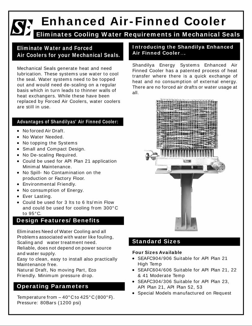
Shandilya Energy Systems Enhanced AirFinned Cooler has a patented process of heattransfer where there is a quick exchange ofheat and no consumption of external energy.There are no forced air drafts or water usage atall.
Introducing the Shandilya EnhancedAir Finned Cooler….
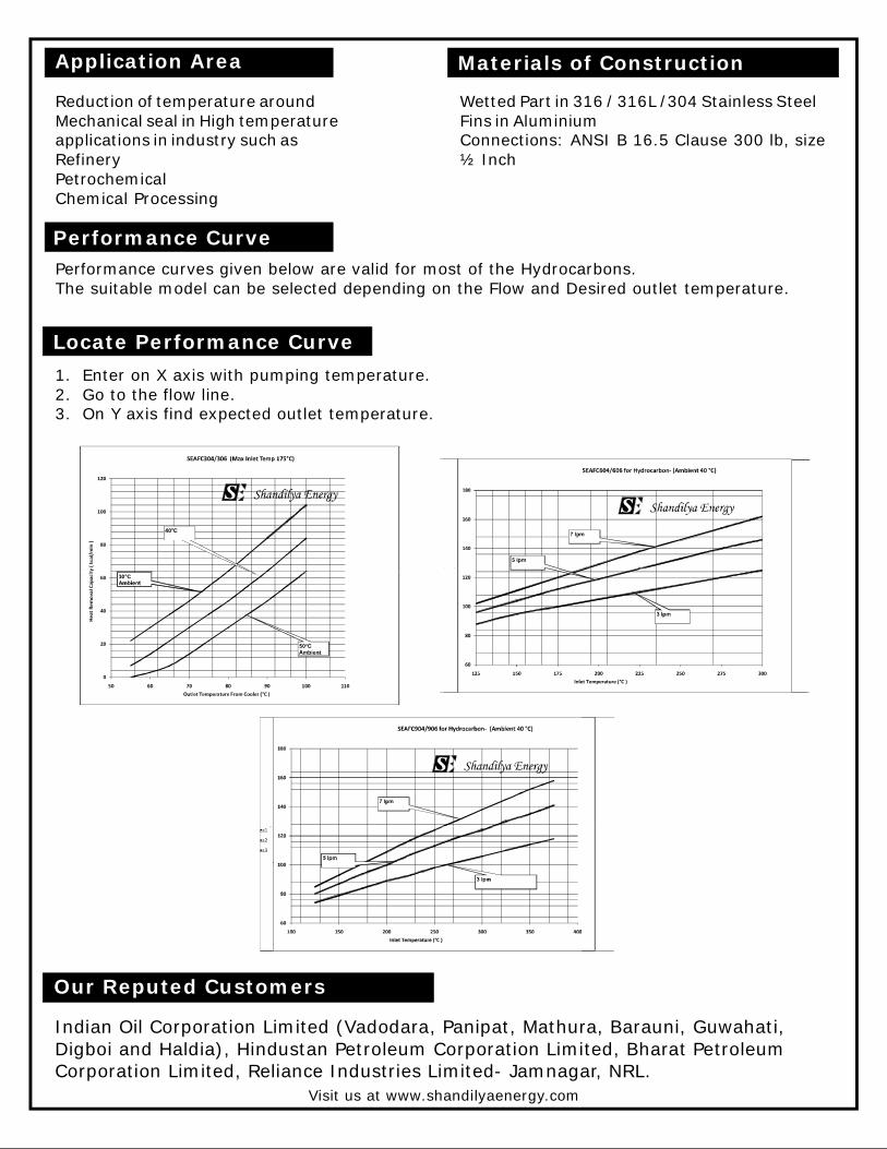
Performance CurvePerformance curves given below are valid for most of the Hydrocarbons.The suitable model can be selected depending on the Flow and Desired outlet temperature.
Reduction of temperature aroundMechanical seal in High temperatureapplications in industry such asRefineryPetrochemicalChemical Processing
Wetted Part in 316 / 316L /304 Stainless SteelFins in AluminiumConnections: ANSI B 16.5 Clause 300 lb, size½ Inch
Materials of Construction
1. Enter on X axis with pumping temperature.2. Go to the flow line.3. On Y axis find expected outlet temperature.
Locate Performance Curve
Application Area
Indian Oil Corporation Limited (Vadodara, Panipat, Mathura, Barauni, Guwahati,Digboi and Haldia), Hindustan Petroleum Corporation Limited, Bharat PetroleumCorporation Limited, Reliance Industries Limited- Jamnagar, NRL.
Visit us at www.shandilyaenergy.com
Our Reputed Customers
Shandilya Mechanical Seal Support System.API Plan 53C for Mechanical Seal Support System
The Shandilya Modified Plan 53C is a constantdifferential pressure barrier fluid sealingsystem. All units comply with and exceed API682 Plan 53C requirements.
Designed per ASME Section VIII,Division LMeets requirements of the EuropeanPressure Equipment Directive 97/ 23/EC.Available with 20 liters (5 gallon) auniversal range for all seal size.Can be supplied for new pumps orretrofitted to existing pumps from anypump manufacturer.Offers a proven history in improving seallife, particularly under varying suctionpressure.Provides an excellent mechanical sealingenvironment in the most demandingprocess conditions.
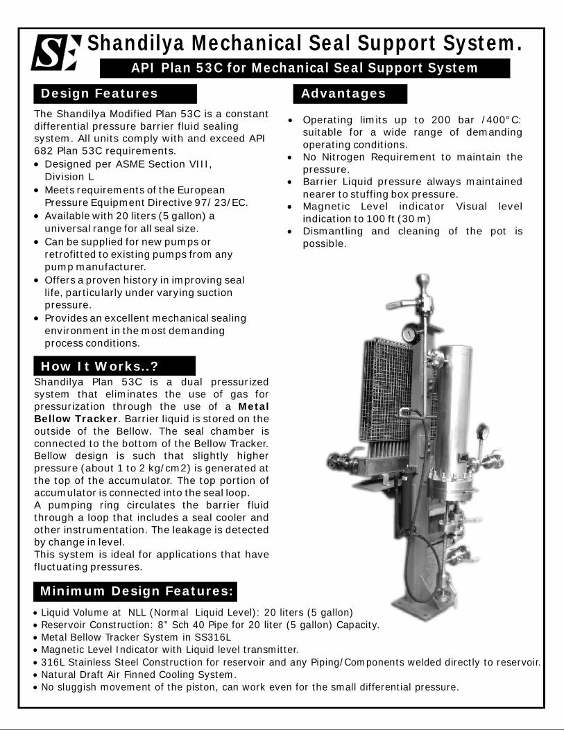
Shandilya Plan 53C is a dual pressurizedsystem that eliminates the use of gas forpressurization through the use of a
. Barrier liquid is stored on theoutside of the Bellow. The seal chamber isconnected to the bottom of the Bellow Tracker.Bellow design is such that slightly higherpressure (about 1 to 2 kg/cm2) is generated atthe top of the accumulator. The top portion ofaccumulator is connected into the seal loop.A pumping ring circulates the barrier fluidthrough a loop that includes a seal cooler andother instrumentation. The leakage is detectedby change in level.This system is ideal for applications that havefluctuating pressures.
MetalBellow Tracker
AdvantagesDesign Features
How It Works..?
Minimum Design Features:
Operating limits up to 200 bar /400°C:suitable for a wide range of demandingoperating conditions.No Nitrogen Requirement to maintain thepressure.Barrier Liquid pressure always maintainednearer to stuffing box pressure.Magnetic Level indicator Visual levelindication to 100 ft (30 m)Dismantling and cleaning of the pot ispossible.
Liquid Volume at NLL (Normal Liquid Level): 20 liters (5 gallon)Reservoir Construction: 8” Sch 40 Pipe for 20 liter (5 gallon) Capacity.Metal Bellow Tracker System in SS316LMagnetic Level Indicator with Liquid level transmitter.316L Stainless Steel Construction for reservoir and any Piping/Components welded directly to reservoir.Natural Draft Air Finned Cooling System.No sluggish movement of the piston, can work even for the small differential pressure.
Design Features API Plan 53A API Plan 53B API Plan 53C ShandilyaPlan 53C
Need to evaluate stuffing box pressure Yes Yes No NoBarrier fluid pressure Maximum stuffing
box pressure + 2kg/cm2
Maximum stuffingbox pressure + 2kg/cm2
stuffing boxpressure + 1 - 2kg/cm2
stuffing boxpressure + 1 - 2kg/cm2
Differential pressure between barrier fluid and stuffing box fixed No No Partial Partial
Barrier fluid pressure automatically changes with varying stuffingbox pressure
No No Yes Yes
Suitable for use with low suction pressure Yes Yes No YesNitrogen Gas required Yes Yes No NoNitrogen absorption into barrier fluid Yes No No NoInstrumental requirement More More less lessSuitability for low variation in stuffing box pressure Yes Yes No YesLarge amount of useable seal barrier fluid Yes No No YesThermal degradation of working fluid Slow Fast Fast SlowMagnetic level indicator No No Yes YesFlow restriction of barrier liquid due to extra cooler No Yes Yes LessPower consumed by Mechanical Seals More More Less LessCan work when inboard seal is not reversed balanced No No Yes YesEffect of Solar Radiation Yes Yes No No
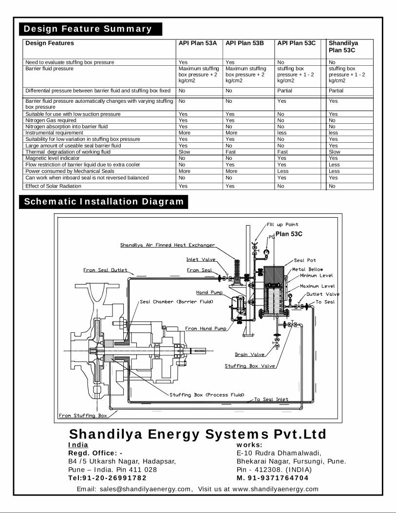
Schematic Installation Diagram
Design Feature Summary
Email: [email protected], Visit us at www.shandilyaenergy.com
Shandilya Energy Systems Pvt.LtdRegd. Office: -
Tel:91-20-26991782
India
B4 /5 Utkarsh Nagar, Hadapsar,Pune – India. Pin 411 028
works:
M. 91-9371764704
E-10 Rudra Dhamalwadi,Bhekarai Nagar, Fursungi, Pune.Pin - 412308. (INDIA)
Shandilya Magnetic Level IndicatorProviding Solution to the Most Common Practical Problems
Shandilya magnetic level indicators are low-maintenance alternatives to sight glasses andother level indicators. They provide longDistance level indication while reducing leakpoints and fugitive emissions.
It is commonly used for visual level indicationof liquids, which attack glass or are hazardous,flammable, toxic, aggressive, agitated,contaminated and under high temperature &pressure i.e. for services, where glass gaugesare unsafe or over the period of time become sodirty that they are not visible.
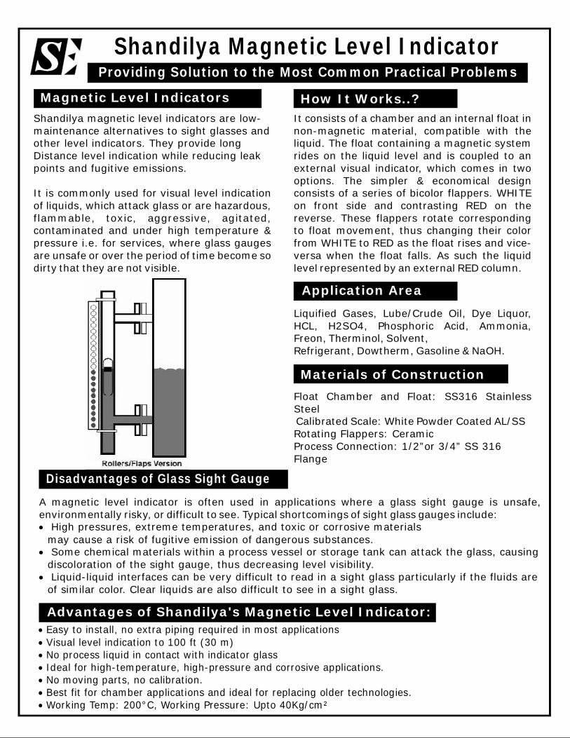
It consists of a chamber and an internal float innon-magnetic material, compatible with theliquid. The float containing a magnetic systemrides on the liquid level and is coupled to anexternal visual indicator, which comes in twooptions. The simpler & economical designconsists of a series of bicolor flappers. WHITEon front side and contrasting RED on thereverse. These flappers rotate correspondingto float movement, thus changing their colorfrom WHITE to RED as the float rises and vice-versa when the float falls. As such the liquidlevel represented by an external RED column.
How It Works..?Magnetic Level Indicators
Liquified Gases, Lube/Crude Oil, Dye Liquor,HCL, H2SO4, Phosphoric Acid, Ammonia,Freon, Therminol, Solvent,Refrigerant, Dowtherm, Gasoline & NaOH.
Application Area
Float Chamber and Float: SS316 StainlessSteelCalibrated Scale: White Powder Coated AL/SSRotating Flappers: CeramicProcess Connection: 1/2”or 3/4” SS 316Flange
Materials of Construction
A magnetic level indicator is often used in applications where a glass sight gauge is unsafe,environmentally risky, or difficult to see. Typical shortcomings of sight glass gauges include:
High pressures, extreme temperatures, and toxic or corrosive materialsmay cause a risk of fugitive emission of dangerous substances.Some chemical materials within a process vessel or storage tank can attack the glass, causingdiscoloration of the sight gauge, thus decreasing level visibility.Liquid-liquid interfaces can be very difficult to read in a sight glass particularly if the fluids areof similar color. Clear liquids are also difficult to see in a sight glass.
Disadvantages of Glass Sight Gauge
Advantages of Shandilya's Magnetic Level Indicator:
Easy to install, no extra piping required in most applicationsVisual level indication to 100 ft (30 m)No process liquid in contact with indicator glassIdeal for high-temperature, high-pressure and corrosive applications.No moving parts, no calibration.Best fit for chamber applications and ideal for replacing older technologies.Working Temp: 200°C, Working Pressure: Upto 40Kg/cm²
Shandilya Mechanical Seal Support System.API Plan 52 and 53A for Mechanical Seal Support System
Liquid Volume at NLL (Normal Liquid Level): 20 liters (5 gallon)Reservoir Construction: 8” Sch 40 Pipe for 20 liter (5 gallon) Capacity.LED Based Magnetic Level Indicator316L Stainless Steel Construction for reservoir and any Piping/Components welded directly toreservoir.Seal Connections: 18mm (0.75in) minimum for shaft size larger than 60mm (2.5in)Internal Cooling Coil: SS316L Seamless TubingPressure Switch and Pressure Gauge: High Pressure alarm for Arrangement 2 Seals, Lowpressure alarm for Arrangement 3 seals.Low Level Switch.
Operating limits up to 50 bar / 200°C:suitable for a wide range of demandingoperating conditions.Day and Night visibility with LED BasedMagnetic Level Indicator for optimumvisual level monitoring even from thelonger distance and wide angle.Modular system: combination with awide range of system componentspossibleDismantling and cleaning of the pot ispossible.
.
Advantages
Full Design Compliance with API Standard682 Third Edition, eliminates the need toprovide detailed purchased specification.The vessels are equipped with all essentialconnections for fitting additional components.For ease of dismantling and cleaning the pot isdished end at one end and flanged end at other.The modular system allows vessels to becombined with a wide range of systemcomponents such as, level switch/transmitter,pressure switch/transmitter, base frame, etc.Circulation in accordance with API 682 / ISO21049Robust Construction Providing life cyclerequirements of API
Design Features
How It Works..?
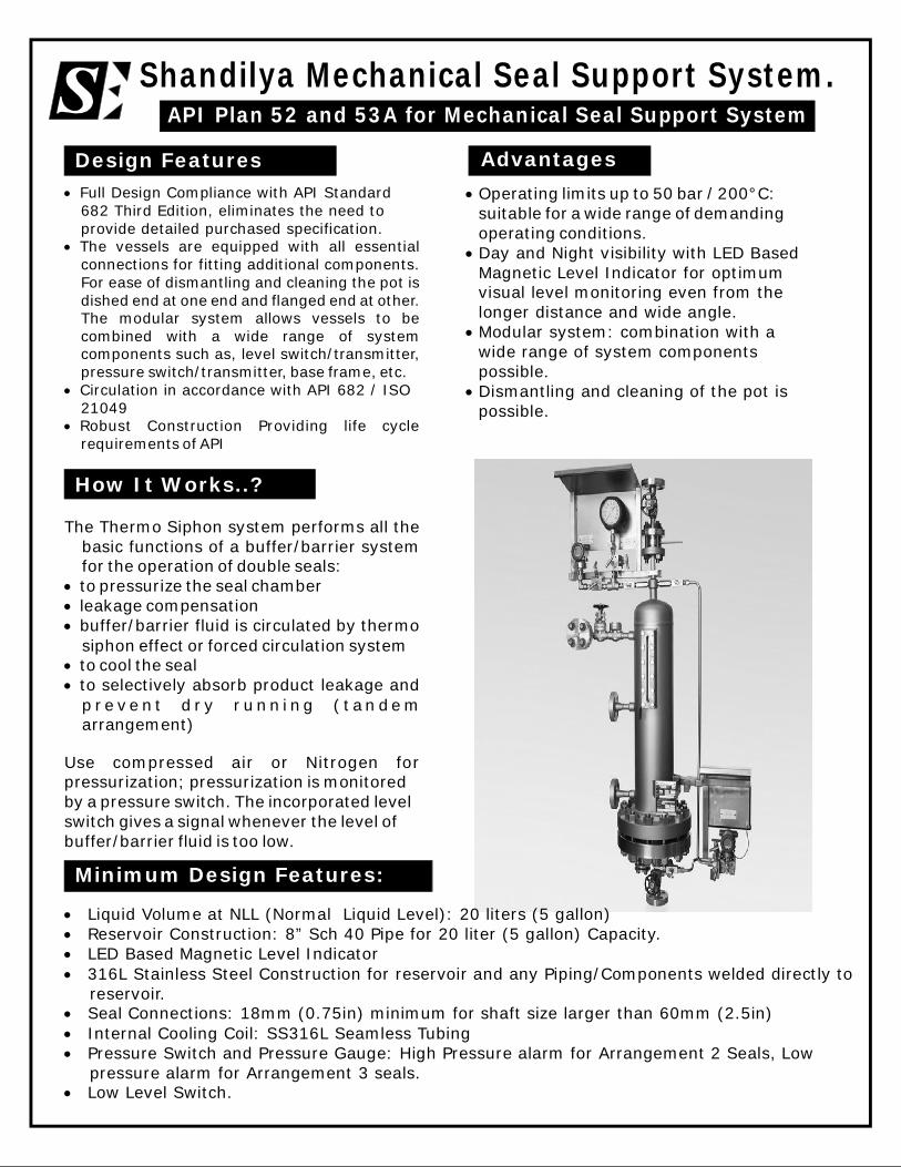
The Thermo Siphon system performs all thebasic functions of a buffer/barrier systemfor the operation of double seals:to pressurize the seal chamberleakage compensationbuffer/barrier fluid is circulated by thermosiphon effect or forced circulation systemto cool the sealto selectively absorb product leakage andp re ve n t d r y r unn i ng ( t an de marrangement)
Use compressed air or Nitrogen forpressurization; pressurization is monitoredby a pressure switch. The incorporated levelswitch gives a signal whenever the level ofbuffer/barrier fluid is too low.
Minimum Design Features: