EngyVolt RV12 and RV15 - portal.endress.com · EngyVolt RV12: active, reactive and apparent power,...
12
Application For measuring voltage, frequency, current, power, as well as imported and exported active and reactive power • in low-voltage systems with a maximum nominal voltage of 500 V L-L (289 V L/N) • in single-phase and three-phase power systems with 3 or 4 wires Your benefits • Multifunction • Pulse output and/or MODBUS module • Top-hat rail installation or panel mounting • Easy to use Technical Information EngyVolt RV12 and RV15 Multifunctional electrical energy meters for top-hat rail installation or panel mounting TI01025K/09/EN/01.11 71154752
Transcript of EngyVolt RV12 and RV15 - portal.endress.com · EngyVolt RV12: active, reactive and apparent power,...

Application
For measuring voltage, frequency, current, power, as wellas imported and exported active and reactive power• in low-voltage systems with a maximum nominal
voltage of 500 V L-L (289 V L/N)• in single-phase and three-phase power systems with 3
or 4 wires
Your benefits
• Multifunction• Pulse output and/or MODBUS module• Top-hat rail installation or panel mounting• Easy to use
Technical Information
EngyVolt RV12 and RV15Multifunctional electrical energy metersfor top-hat rail installation or panel mounting
TI01025K/09/EN/01.1171154752

EngyVolt RV12 and RV15
2 Endress+Hauser
Function and system design
Measuring principle The multifunction electrical energy meters are designed to record, display and transmit electrical measuredvalues in low-voltage systems with a maximum nominal voltage of 500 V L-L (289 V L/N), current connectedvia low-voltage current converter x/5 A at a nominal frequency of 45 to 66 Hz. They are suitable for use insingle-phase power systems, and in three-phase power systems with three or four wires.
Among other values, the multifunction electrical energy meters measure the voltage, frequency, current, power,power factor, total harmonic distortion (THD) as well as active power and reactive power.
The EngyVolt RV12 with housing according to DIN 43880 is designed for mounting on a top-hat rail, whilethe EngyVolt RV15 is designed for installation in a panel.
Input
Measured variable Measured process variables
Current (L1, L2, L3,), voltage (L1/N, L2/N, L3/N or L1/L2, L2/L3, L3/L1 respectively), frequency in low-voltage systems
Calculated process variables
EngyVolt RV12: active, reactive and apparent power, power factor (Cos-Phi), imported and exported activeand reactive energy, total harmonic distortion (current L1, L2, L3; voltage L1/N, L2/N, L3/N or L1/L2, L2/L3, L3/L1 respectively), neutral current, max. current (L1, L2, L3, N) 1), max. active power 1).
EngyVolt RV15: active, reactive and apparent power, total harmonic distortion (current L1, L2, L3; voltage L1/N, L2/N, L3/N or L1/L2, L2/L3, L3/L1 respectively), active and reactive energy, neutral current, max. current(L1, L2, L3, N) 1), max. active power 1).
Measuring range Nominal voltage 100 to 289 V AC L-N (173 to 500 V AC L-L)
Voltage measuring range 25 to 600 V
Maximum short-durationovervoltage
2 x nominal voltage for 1-second application repeated 5 times in 5-minute intervals
Nominal current (secondary) 5 A AC RMS
Secondary current measuring range 0.05 to 6 A
Maximum short-durationovercurrent
10 x nominal current for 1-second application repeated 5 times in 5-minute intervals
Primary current measuring range 1 to 9 999 A (per phase)
Frequency 45 to 66 Hz
Nominal power (secondary) 1 445 W (3-phase 4 325 W)
Power measuring range (secondary) 14.45 to 2 080 W (3-phase: 43.25 to 6 228 W) 1)
Power measuring range (primary) 5 to 12 450 000 W (12.45 MW) 1)
Power consumption voltage circuits <0.2 VA per phase
Power consumption current circuits <0.6 VA per phase
1) depending on CT
Energy counter 0 to 9 999 999.9 Wh, kWh, MWh / varh, kvarh, Mvarh
1) calculated from the integrated averages and representation as maximum value over an adjustable interval of 5, 8, 10, 15, 20, 30, 60 min
EngyVolt RV12 and RV15
Endress+Hauser 3
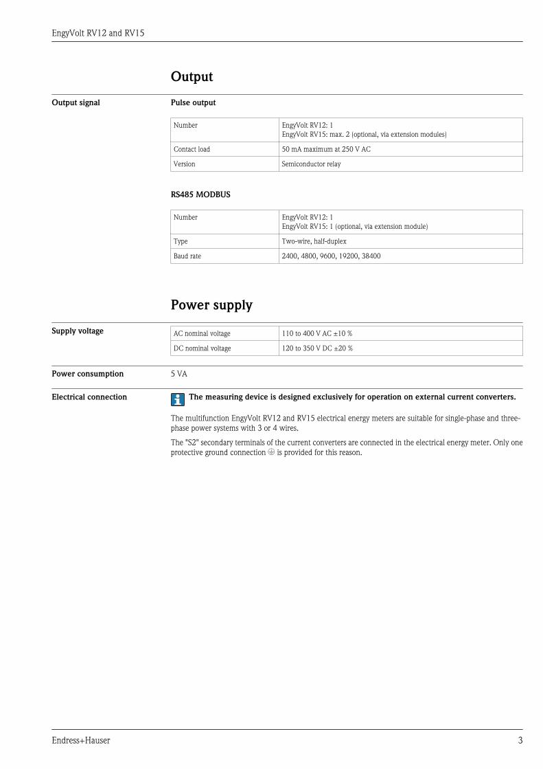
Output
Output signal Pulse output
Number EngyVolt RV12: 1EngyVolt RV15: max. 2 (optional, via extension modules)
Contact load 50 mA maximum at 250 V AC
Version Semiconductor relay
RS485 MODBUS
Number EngyVolt RV12: 1EngyVolt RV15: 1 (optional, via extension module)
Type Two-wire, half-duplex
Baud rate 2400, 4800, 9600, 19200, 38400
Power supply
Supply voltage AC nominal voltage 110 to 400 V AC ±10 %
DC nominal voltage 120 to 350 V DC ±20 %
Power consumption 5 VA
Electrical connection The measuring device is designed exclusively for operation on external current converters.
The multifunction EngyVolt RV12 and RV15 electrical energy meters are suitable for single-phase and three-phase power systems with 3 or 4 wires.
The "S2" secondary terminals of the current converters are connected in the electrical energy meter. Only oneprotective ground connection * is provided for this reason.

EngyVolt RV12 and RV15
4 Endress+Hauser
Connection to 1-phase, 2-wire
N L3 L2 L1 AUX
PULSE MODBUS CT INPUTS
B A G -I3+ -I2+ -I1+
L1
NS1P1
L1
N
VOLTAGE INPUTS
L1
N
L1
N
AU
X
NL3L2L1
+I1- +I2- +I3-
1 2
S1P1
LOAD
fast
blow fuse
1 A
slow blow fuse 1 A
LOAD
Auxiliary supply
fast
blow fuse
1 A
Auxilia
ry s
upply
slow
blo
w fuse
1 A
LOAD LOAD
A0016364-EN
å 1 Electrical connection for 1-phase, 2-wire
1 Connection for top-hat rail device2 Connection for panel-mounted device
EngyVolt RV12 and RV15
Endress+Hauser 5
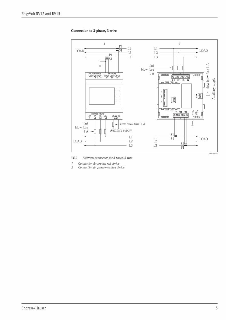
Connection to 3-phase, 3-wire
N L3 L2 L1 AUX
PULSE MODBUS CT INPUTS
B A G -I3+ -I2+ -I1+
P1S1
VOLTAGE INPUTS
L1
AU
X
NL3L2L1
+I1- +I2- +I3-
1 2
L2
L3
L1
L2
L3
L1
L2
L3
P1S1
S1P1
S1P1
fast
blow fuse
1 A
slow blow fuse 1 A
LOAD
Auxiliary supply
fast
blow fuse
1 A
Auxilia
ry s
upply
slow
blo
w fuse
1 A
LOADLOAD
LOAD
L1
L2
L3
A0016366-EN
å 2 Electrical connection for 3-phase, 3-wire
1 Connection for top-hat rail device2 Connection for panel-mounted device

EngyVolt RV12 and RV15
6 Endress+Hauser
Connection to 3-phase, 4-wire
N L3 L2 L1 AUX
PULSE MODBUS CT INPUTS
B A G -I3+ -I2+ -I1+
VOLTAGE INPUTS
L1
AU
X
NL3L2L1
+I1- +I2- +I3-
1 2
L2
L3
L1
L2
L3
L1
L2
L3
P1S1
S1P1
S1P1
N N
N
S1P1
P1S1
P1S1
LOAD
fast
blow fuse
1 A
slow blow fuse 1 A
LOAD
Auxiliary supply
fast
blow fuse
1 A
Auxilia
ry s
upply
slow
blo
w fuse
1 A
LOAD LOAD
L1
L2
L3
N
A0016367-EN
å 3 Electrical connection for 3-phase, 4-wire
1 Connection for top-hat rail device2 Connection for panel-mounted device
Connection of extension modules for EngyVolt RV15
RS485 Gnd
AB
1 2
RE
LA
Y
RE
LA
Y
A0016374-EN
å 4 Extension module connection
1 RS485 / pulse module2 Pulse module
Terminals Screw-clamp terminals 0.05 to 2.5 mm² (30 to 14 AWG)

EngyVolt RV12 and RV15
Endress+Hauser 7
Performance characteristics
Reference operatingconditions
Reference temperature 23 °C ±1 °C (73.4 °F ±1.8 °F)
Input wave form 50 or 60 Hz ±2 %
Sinusoidal (distortion factor < 0.005)
Supply voltage Nominal voltage ±1 %
Supply voltage frequency (with AC) Nominal frequency ±1 %
Supply voltage wave form Sinusoidal (distortion factor < 0.05)
Maximum measured error Extended measured error: IEC 688: 1992
Current (A) 0.5 % of nominal current
Voltage (V) 0.5 % of max. nominal voltage (4 % for I2 in 3-phase 3-wire operation)
Calculated neutral current (A) 4 % of nominal current
Frequency (Hz) 0.1 Hz
Power factor (PF = Cos-Phi) 0 to 1Power factor is only indicated when the measured VA is over 3 % of range maximum
Active power (W) ±1 % of nominal power
Reactive power (var) ±1 % of nominal power
Apparent power (VA) ±1 % of nominal power
Active energy (kWh) Class 1 (IEC 62053-21)
Reactive energy (kvarh) ±1 % of measuring range
THD 1 % up to 31st harmonic
Display repetition rate
1 s typically up to >99 % of the full scale value
Measurement and calculation interval
Max. 300 ms (maximum with %THD measurement)
Influence of ambienttemperature
Current and voltage: 0.013 %/°C (0.0072 %/°F) of nominal value
Power: 0.018 %/°C (0.01 %/°F) of measuring range
Error change due to variationof an influence quantity in themanner described in Section 6of IEC 688:1992
2 x error allowed for the reference condition applied in the test. Error due to temperature variation as above.
Error in measurement when ameasurand is within itsmeasuring range, but outsideits reference range
2 x error allowed at the end of the reference range adjacent to the section of the measuring range, where themeasurand is currently operating / being tested.
Warm-up period 1 minute
EngyVolt RV12 and RV15
8 Endress+Hauser
Installation
Mounting location EngyVolt RV12
Housing for top hat rail mounting as per DIN 43880
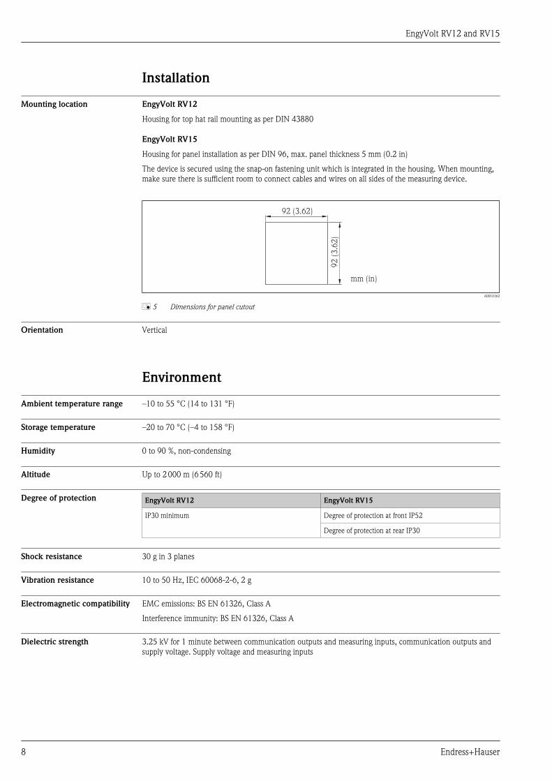
EngyVolt RV15
Housing for panel installation as per DIN 96, max. panel thickness 5 mm (0.2 in)
The device is secured using the snap-on fastening unit which is integrated in the housing. When mounting,make sure there is sufficient room to connect cables and wires on all sides of the measuring device.
92 (3.62)
92 (
3.6
2)
mm (in)
A0016362
å 5 Dimensions for panel cutout
Orientation Vertical
Environment
Ambient temperature range –10 to 55 °C (14 to 131 °F)
Storage temperature –20 to 70 °C (–4 to 158 °F)
Humidity 0 to 90 %, non-condensing
Altitude Up to 2 000 m (6 560 ft)
Degree of protection EngyVolt RV12 EngyVolt RV15
IP30 minimum Degree of protection at front IP52
Degree of protection at rear IP30
Shock resistance 30 g in 3 planes
Vibration resistance 10 to 50 Hz, IEC 60068-2-6, 2 g
Electromagnetic compatibility EMC emissions: BS EN 61326, Class A
Interference immunity: BS EN 61326, Class A
Dielectric strength 3.25 kV for 1 minute between communication outputs and measuring inputs, communication outputs andsupply voltage. Supply voltage and measuring inputs

EngyVolt RV12 and RV15
Endress+Hauser 9
Mechanical construction
Dimensions EngyVolt RV12 (top-hat rail)
58 (2.28)
48 (1.89)
32.2 (1.27)
61.5
(2.4
2)
45 (
1.7
7)
mm (in)
93.6
(3.6
9)
N L3 L2 L1 AUX
PULSE MODBUS CT INPUTS
B A G -I3+ -I2+ -I1+
VOLTAGE INPUTS
90.5
(3.5
6)
71.3 (2.81)
A0016363
å 6 Device dimensions
EngyVolt RV15 (panel-mounted)
96 (
3.7
8)
64.1 (2.52)
96 (3.78)58 (2.28)
*
*
77.5 (3.05)
83.6 (3.29)
**
**mm (in)
A0016361
å 7 Device dimensions
* Basic device** Basic device with extension module
Panel thickness
1 to 5 mm (0.04 to 0.2 in.)
Weight 300 g (0.66 lb)
Materials Polycarbonate as per UL94V0

EngyVolt RV12 and RV15
10 Endress+Hauser
Operability
Local operation
N L3 L2 L1 AUX
PULSE MODBUS CT INPUTS
B A G -I3+ -I2+ -I1+
VOLTAGE INPUTS
1
2
3
RV12 RV15
A0016505
å 8 Display and operating elements of the EngyVolt devices
1 Three-line display2 Symbol for parameter displayed3 Operating keys
The display screen is used in 2 operating modes:• Display mode to indicate measured values• Configuration mode of the multifunction electrical energy meter
Display mode
The measured values are shown on the backlit liquid crystal display. The user can call up and run through 15different views using the operating elements on the front panel.
Configuration mode
The abbreviation for the parameter is displayed in the top display row in the configuration mode. The middlerow displays the parameter value. The bottom row is used to confirm the set value of the parameter. Generallyspeaking, the "A" and "P/PF" keys change the value of the parameter; the "E" key confirms the change / settingand skips to the next display screen (next parameter).

EngyVolt RV12 and RV15
Endress+Hauser 11
Certificates and approvals
4 mark Declaration of Conformity
The product meets the requirements of the harmonized European standards.
As such, it complies with the legal specifications of the EC directives.
The manufacturer confirms successful testing of the product by affixing to it the 4 mark.
Other standards andguidelines
• IEC 60529:Degrees of protection provided by enclosures (IP code)
• IEC 61010-1: 2001Safety requirements for electrical equipment for measurement, control and laboratory use
Ordering informationDetailed ordering information is available from the following sources:• In the Product Configurator on the Endress+Hauser website: www.endress.com ® Select country ®
Instruments ® Select device ® Product page function: Configure this product• From your Endress+Hauser Sales Center: www.endress.com/worldwide
Product Configurator - the tool for individual product configuration• Up-to-the-minute configuration data• Depending on the device: Direct input of measuring point-specific information such as measuring range
or operating language• Automatic verification of exclusion criteria• Automatic creation of the order code and its breakdown in PDF or Excel output format• Ability to order directly in the Endress+Hauser Online Shop
Documentation• Operating Instructions EngyVolt RV12: BA01039K/09• Operating Instructions EngyVolt RV15: BA01040K/09• System components brochure, "Indicators with and without control unit for field and panel mounting, power
supplies, barriers, transmitters, energy managers, batch controllers, and surge arresters": FA016K/09

Instruments International
Endress+HauserInstruments International AGKaegenstrasse 24153 ReinachSwitzerland
Tel.+41 61 715 81 00Fax+41 61 715 25 [email protected]
TI01025K/09/EN/01.1171154752EH-COSIMA


![Java High Performance Reactive Programmingiproduct.org/.../04/IPT_Reactive_Programming_Java.pdf · Reactive Programming. Functional Programing Reactive Programming [Wikipedia]: a](https://static.fdocuments.net/doc/165x107/5ec60814df097e0643499b13/java-high-performance-reactive-reactive-programming-functional-programing-reactive.jpg)