
ENGR 411 Senior Capstone II Final Report
101
Indiana University - Purdue University Fort Wayne Department of Engineering ENGR 411 Senior Capstone II Final Report Project Title: Heat Sink Furnace Unloader Team Members: Blane Baumgartner (ME) Blaine Cox (ECE) Eric Culver (ME) Amanda Peters (EE) Natasha Sorokin (ME) Faculty Advisors: Dr. Zhuming Bi Dr. Yanfei Liu Date: 5 May 2014
Transcript of ENGR 411 Senior Capstone II Final Report

Indiana University - Purdue University Fort Wayne Department of Engineering
ENGR 411 Senior Capstone II Final Report
Project Title: Heat Sink Furnace Unloader
Team Members: Blane Baumgartner (ME) Blaine Cox (ECE) Eric Culver (ME) Amanda Peters (EE) Natasha Sorokin (ME) Faculty Advisors: Dr. Zhuming Bi Dr. Yanfei Liu
Date: 5 May 2014

Table of Contents Acknowledgements ............................................................................................................................. 1 Abstract ............................................................................................................................................... 2 Section 1: Original Design
1.1 Problem Statement ............................................................................................................ 4 1.1.1 Requirements and Specifications ..................................................................... 4 1.1.2 Given Parameters ............................................................................................. 5 1.1.3 Design Variables ................................................................................................ 6 1.1.4 Limitations and Constraints .............................................................................. 6
1.2 Detailed Design .................................................................................................................. 7 1.2.1 Mechanical Sub-Systems .................................................................................. 8 1.2.2 Electrical Sub-Systems .................................................................................... 20
Section 2: Build Process 2.1 Mechanical Build Process
2.1.1 Part Transportation ........................................................................................ 35 2.1.2 End- Effector ................................................................................................... 36 2.1.3 Frame............................................................................................................... 37 2.1.4 Additional Sub-Systems .................................................................................. 40
2.2 Electrical Build Process 2.2.1 Controller ........................................................................................................ 44 2.2.2 Sensing ............................................................................................................ 45 2.2.3 Power Supplies ................................................................................................ 46 2.2.4 Indicator Lights................................................................................................ 49 2.2.5 Touchscreen .................................................................................................... 50 2.2.6 Programming .................................................................................................. 52
2.3 Project Cost ...................................................................................................................... 59 Section 3: Testing............................................................................................................................... 61 Section 4: Evaluation and Recommendations
4.1 Evaluation ......................................................................................................................... 67 4.2 Recommendations ........................................................................................................... 69
Conclusion ......................................................................................................................................... 70 References ......................................................................................................................................... 72

1
Acknowledgements The design team would like to extend a special thank you to Parker Hannifin for sponsoring this endeavor and making the project possible. The insight and expertise offered by Jessica Hunnicutt, John Yurek, Steve Moore, Eric Bickford, Rich Davenport and Steve O’Shaughnessey helped the group tremendously in finalizing the design and building and testing the prototype. The design team would also like to express gratitude to the project advisors Dr. Zhuming Bi and Dr. Yanfei Liu for their guidance and support. Dr. Bi and Dr. Liu stayed in touch with the group to check the progress of the project and offer advice and constructive criticism for each stage of the project development.

2
Abstract
Parker Hannifin Precision Cooling Business Unit needed an automated unloader for a heat sink
brazing furnace in order to maximize productivity and minimize wasted time, and labor. With
minimal operator intervention, the device should unload heat sinks from the conveyor belt as they
exit the furnace, and place them into a storage container.
This paper describes the entire design process to create a device that meets the requirements
stated above. The first section describes the original design of the unloader based on
requirements, given parameters and constraints. The second section details the build process
and design modifications that were introduced during this semester. This section also includes
pictures from different stages of the build process. The third section details the tests carried out
to validate the device. The fourth section contains overall evaluation of the design and
conclusions based on the completed project.

3
Section 1: Original Design

4
1.1 Problem Statement
Parker Hannifin Precision Cooling Business Unit of New Haven, Indiana, requested a Heat Sink Furnace Unloader. The device should increase the efficiency of the operator and reduce the chances of damaged products. Currently, an operator assembles and loads heat sinks at one end of the furnace, at the same time, he or she is responsible for unloading them at the other end. The goal of the unloader is to reduce the time for the operator to walk to the unloading end of the furnace, and allow the operator to concentrate on assembling and loading heat sinks. 1.1.1 Requirements and Specifications The detailed requirements and specifications are described as follows.
The device must unload heat sinks from the production line without causing defects. An unloading failure is defined by (1) a fall of a heat sink to the floor or (2) a scratch or gouge 0.015” of an inch deep incurred by the heat sink.
The device must load heat sinks into a specified box with an accuracy of the placement within 0.1”. This criterion was justified based on the fact that five heat sinks are placed in the box without an interference.
After an unloading operation, the device must be capable of returning its home position in 40 seconds. The time corresponded to a minimized travel time for the next heat sink to arrive in the unload position. The fastest belt speed of 12.3 in/min was used to come up with a conservative estimation.
The device must either alert the operator to place cardboard in the box or automate the same process.
The device must automate the storing away of boxes in order for more boxes to be loaded or alert the operator to do so.
The device must be able to be toggled on and off. The main reason for this requirement is that dunnage, or dummy heat sinks, must run through the furnace before and after the production line of heat sinks to stabilize the temperature in the furnace. The dunnage should not be unloaded and is allowed to fall off of the conveyor at the end of the line into a bucket. The device must be ready to unload a heat sink within 38.5 seconds of being toggled on.
The device must be portable so that Parker engineers can move the device to a different conveyor belt if needed.
The device must be safe to the operator and environment.

5
1.1.2 Given Parameters
The following parameters are given by Parker Hannifin, which are not allowed to be modified during the project development:
The conveyor belt speed is ranged from 4.7 in/min to 12.3 in/min. This speed is determined by multiple factors including the size of heat sinks, temperature and required time of heat exposure. However, initial design will be based on a constant belt speed of 6.2 in/min. This speed does not vary within one production order, which always contains one type of heat sink.
The dimensions of the heat sinks are on average: Length = 5.27”, Width = 2.51”, Height = 0.59”. The design should be able to accommodate slight variations of the above dimensions.
The nominal weight of a heat sink is 2.13 lb.
The dimensions of the box for unloaded heat sinks are Length = 14.125”, Width = 8.625”, Height = 6.125”.
The conveyor belt has a width of 5” with travel distance of 36” from the furnace exit to the end of the belt.
The maximum temperature of a heat sink at its unloading position is Tmax = 200 °F.
The heat sinks are aligned in a straight line with spacing at the length of a heat sink and parallel to the path of motion; however, the orientation of a heat sink may vary with a maximized 15 degrees from the path as they exit the furnace.
The weight limit of heat sinks in one box is 30 lbs according to Parker regulations.

6
1.1.3 Design Variables The following factors are treated as design variables; they can be selected to satisfy the given requirements.
Means of unloading, for example, o Contact – part or material that comes into contact with the heat sink o Transportation – mechanism that moves heat sink from conveyor belt to the box
Operator notification, for example, lights or alarm
Sensor types and configurations – parts of device that will detect when heat sink is ready for unloading and to act as safeguards, for example, non-contact and contact
Power supply, for example, DC or AC
Controller – device that processes sensor information and user input to control mechanics for example, custom coding, PLC, PC, or a combination
Material used for construction, for example, aluminum or wood. 1.1.4 Limitations and Constraints The limitations and constraints for the Heat Sink Furnace Unloader must be accounted for in order to meet the specifications and requirements from Parker Hannifin:
Space limitations: due to the limited space around the conveyor exiting the furnace, the unloader system must not exceed a 3’x 3’ area at the side of the conveyor, and a 2’x 5’ area at the end of the conveyor.
Cost: the monetary cost of the project must be under $5000.
Maintenance: the furnace unloader must be easily repairable if a part or component were to fail.
Accessibility for manual intervention: if needed, the unloading process at the furnace must be able to be performed manually; in other words, the unloader design must leave the conveyor belt open and accessible.

7
1.2 Detailed Design After a careful comparison of all design choices and feasibility study, the final design is shown in Figure 1. The main frame for the unloader adopts a modular structure for easily assembly and maintenance, a SCARA robot is used to transport parts, and a vacuum suction is designed as the end effector to pick and place heat sinks.
Figure 1: Final design assembly.
The details of the major sub-systems of the automated furnace unloader are presented in the following two sections: mechanical and electrical/computer components.

8
1.2.1 Mechanical Sub-Systems
Part Transportation – Articulated Robot Arm A primary function of the unloader is to transport parts from the conveyer to storage boxes. At least three motion axes are needed to perform this task. Customized designs of the mechanism will involve a high cost for actuators and increase the risk of failures in integrating the system in a short period of time. It is found that a SCARA robot arm was directly available from Parker, its specifications were examined against our design requirements, and it was chosen to be used to fulfill the part transportation aspect of the design. This robot was manufactured by Intelligent Actuator, model IH-500-150. The robot is powered by single phase AC 220 volts and uses four electric motors to generate the end-effector’s motion. The overall weight of the robot is 77 lbf and is rated to be capable of lifting 4.4 lbf (8.8 lbf maximum). As shown in Figure 2, 4 degrees of freedom of the robot as well as its vertical working range are: (1) the rotation along the z axis of the base, (2) the rotation along the z axis of the arm, (3) the rotation along the z axis of the shaft, and (4) the vertical translation along the z axis with of 150 mm. The end-effector tool has a repeatability of ± .02 mm, which is well within the determined tolerance needed to prevent the heat sinks from coming into contact with one another when placed in the box. Additionally all 4 degrees of freedom will be needed in order for the heat sink to be properly placed into the box. The overall dimensions of the given SCARA robot can be seen in Figure 2.
Figure 2: Schematic of Intelligent Actuator IH-500-150 (ONExia).

9
One critical limitation of the selected robot is its limited range of motion of 150mm in the vertical direction; the motion of the shaft is insufficient to reach the heat sink to pick it up from the conveyor belt. The solution is to extend the shaft. The extension will be incorporated into the suction assembly and is further discussed in that section. For picking and placing, two compressed air inlets are located on the back of the robot and are routed through the upper and lower arms internally. One of the airlines will then be connected to the vacuum generator on the suction assembly. Space limits are importance concerns in unloader design. Based on the dimensions and the range of motion, the mounting location for the robot was determined and as shown in Figure 3. This location was chosen in relation to the alignment apparatus (discussed later) while allowing enough room for the box to be placed in a location where it is easily removable. The location to the center of the robot base from the front edge of the mounting plate was determined from the length of the alignment system needed to properly orient the heat sink, resulting in 19 inches. The distance from the left edge of the mounting plate to the robot center was determined by the 500 mm reach that the robot arm has when fully extended, and when the center of the vertical shaft is in the center of the 5 inch wide conveyor belt, giving a distance of 7.35 inches.
Figure 3: Mounting location of the robot.
The workspace of the robot is shown in Figure 4 along with the robot arm locations when placing the heat sinks in the box. The black lines show the maximum angle of the robot arms. Blue lines represent the robot arm position for each heat sink placement location. The lower arm has a range

10
of motion from 90 to 270 degrees. The upper arm has a range of motion with respect to the lower arm of ±135 degrees. The shaft of the robot having motion in the vertical direction also has rotational motion of 360 degrees.
Figure 4: Diagram of robot arm positions and motion (green rectangles show box and heat sink
positions).

11
End Effector - Suction The end-effector is to execute picking and placing operations over parts. Of the three concepts for the end-of-arm tooling documented in the report of conceptual designs, the suction concept has been chosen. This concept involves a vacuum generator and suction cup that comes into contact with the top of the heat sink when it is on the conveyor belt. The suction force from the vacuum generator allows the robot to grip the heat sink and move it from the belt to the box. The design of the suction end-of-arm tooling concept is shown in Figure 5.
Figure 5: Components in the integrated end-effector.
With the robot mounted to the cart top, the end of the robot arm cannot vertically reach the heat sink at the conveyor belt. Therefore, an extension of the robot arm shaft is needed. To determine the length of the extension, the end-of-arm tooling dimensions must be known in advance. Therefore, the suction cup and vacuum generator are designed first. The vacuum generator and suction cup must be able to supply enough force to lift and hold the heat sink while the robot is transporting it. The average weight of a heat sink is 2.13 lbs. The weight limit that the robot can pick up is 2 kg, or 4.409 lbs. This means that if the inertial force of objects
Suction Cup
Vacuum Generator
Extension
Robot Shaft Mounting Block
Offset Block

12
due to the acceleration is ignored, all of the end-of-arm tooling must be less than 4.409 lbs– 2.13 lbs = 2.279 lbs. One additional constraint to be considered is that any material coming into contact with the heat sink must be temperature rated to withstand 200°F indefinitely as laid out by the requirements of this project. Consequentially, the suction cup material must be rated for at least 200°F. Because of the long, thin nature of the geometry of the heat sink (typically with 5.27-inch long by 2.51-inch wide, which is a length to width ratio of about 2), it makes sense to select a suction cup based on the length to width ratio since the surface area of the suction is maximized. Therefore, the most common shape of the suction cup, an oval shape has been selected. Oval suction cups were researched from multiple manufacturers. For example, Vaccon, a manufacturer specializing in vacuum products for robotics and automation controls, manufactures many oval suction cups. Most of their suction cups are available in grey silicone material, which is rated from -50°F to 392°F. An oval suction cup closely matching the length to width ratio of the heat sink while being slightly smaller than the heat sink was chosen. It is shown in Figure 6 below. Drawings are shown in Appendix B.
Figure 6: Oval suction cup with 4.09 by 1.56 inches size and 2.6 of the length to width ratio.
The suction cup is 4.09 inches long by 1.56 inches wide (oval inscribed) with a length to width ratio of about 2.6. The suction cup length is 22% less than the heat sink length; the suction cup width is 38% less than the heat sink width. The heat sink has an uncompressed height of 1.30 inches and compresses 0.1 inch for a collapsed height of 1.20 inches. The threaded fitting (1/4” NPTF) is located directly in the center of the cup. The cup has an approximate acting area of 3.16 inches squared as indicated by the manufacturer catalog. The cup with fitting weighs 3.2 oz. or 0.2 lbs. Next, a vacuum generator must be chosen to employ the suction cup. For consistency, this was chosen from Vaccon catalogs as well. The standard Vaccon pump VP00 is a lightweight and small vacuum generator that can be mounted very close to the pickup point. It is shown in Figure 7. It can supply up to 20”Hg or 10 PSI in the M performance level designation. The air supply line takes ¼” outer diameter tubing, which matches the tubing from the robot. Dimensions shown in drawing in Appendix B. The weight that the pump is capable of picking up with the chosen oval suction cup is 31.6 lbs.

13
Figure 7: Vaccon standard pump VP00-60M capable of reaching vacuum levels of 20”Hg.
The vacuum port on the pump has 10-32 threads. Two adapters will be used to go from the suction cup port to the vacuum port on the pump. This involves a 10-32 Male to 10-32 Male adapter and a 10-32 Female to 1/4" NPTF Male adapter made of Nylon, as shown in Figure 8. The adapters will be bought from ARK-PLAS.
Figure 8: Two adapters to go from the suction cup to vacuum pump.
In order to have the suction cup horizontal, the pump must be mounted from its side due to the orientation of the mounting holes and the vacuum port on the pump. It would make sense now to mount the pump to an extension that will extend up to the robot shaft. This would work, but due to the mounting of the extension to the robot shaft, the pump must be offset horizontally to keep the suction cup center at the center of the robot shaft axis. The reason for this is solely to simplify the design. This makes it much easier to orient and locate the heat sink positions at the unload position and the box positions. To calculate the offset of the pump, the tooling that mounts to the robot shaft must be designed at first. It turns out that the robot comes with its own shaft mount block and key shown in Figure 9. This mount is designed so that it does not spin on the robot shaft. Dimensions are shown in Appendix B. The holes to bolt the key to the block are ¼-20 threaded holes (in the block, through holes on the key). Two more custom holes will be added at the bottom of the block with 6-32 UNC threads.
Figure 9: Robot shaft mounting block modified to mount extension plate.

14
Finally, the extension is shown in Figure 10. The top of the extension is made to mount to the side of the key. It also includes a spacer to fit under the key. The spacer has two through holes at 0.138 inch diameter and is made of 6061 Aluminum alloy. The extension plate is made of 6061 Aluminum alloy with ¼-20 through holes that line up with the holes in the key and 0.138 inch diameter through holes for the spacer holes.
Figure 10: Aluminum extension plate and spacer shown with lines for mounting to robot shaft
mounting block.
The length of the extension is found by finding the distance between the bottom of the pump to the center of the key holes in the mounting block. The distance between the bottom of the robot shaft at its bottom position and the surface where the robot is mounted is 6.30 inches. The height of the heat sink, the distance between the conveyor belt surface and the conveyor base surface, and the distance between the conveyor base surface and the surface where the robot is mounted can be subtracted from this distance. Also, the height of the compressed suction cup and the distance between the top of the suction cup and the bottom of the pump (caused by the fittings) can be subtracted to give the distance between the bottom of the robot shaft at its lowest position to the bottom of the pump giving a distance of 3.51 inches. It is necessary to add the space from the bottom of the robot shaft to the center of the key holes. This distance is 0.30 inches. So the distance of extension needed from the center of the key holes to the bottom of the pump is 3.81 inches. The extension has three holes cut out of it to reduce weight. The dimensions are shown in the prints in Appendix B. It also contains a slot for two #4-40 bolts which will be discussed later. For the center of the suction cup to be on the robot shaft axis, an offset block must be utilized. The offset block will be attached to the extension as shown in Figure 11 with two #4-40 bolts. It will be made of 6061 Aluminum alloy. To determine the width of the offset, the distance from the

15
pump to the extension between the nearest two faces must be known. Since the distance from the centerline of the robot shaft to the nearest face of the extension is 0.89 inches, and the width of the pump is 0.63 inches the offset width was determined to be 0.575 inches.
Figure 11: Offset block mounting to extension.
The length of the offset is simply the same as the pump. The location of the holes in the offset block match the mounting holes in the pump, therefore the pump and offset block can both be mounted to the extension plate with two #4-40 bolts. A slot is used in the extension to make the offset block and suction assembly adjustable. The reason for this is because the cart cannot be precisely aligned in the vertical direction every time it is placed at the conveyor. Slightly different locations and orientations of the casters may alter the height and angle of the top of the cart, and therefore the robot and suction locations. For this reason an adjustment in the vertical direction is necessary and will be implemented by the slot in the extension. The payload of the robot is rated at 2 kg and has a maximum of 4 kg. This is equivalent to 4.409 lbf and 8.818 lbf, respectively. The total weight of the suction assembly is 0.7669 lbf. When lifting the heat sink, therefore, the load on the robot is 2.8969 lbf. The design factor for loading is over 1.5.

16
Reconfigurable Frame The frame is mainly to (1) integrate all components together as a functional system and (2) locate and position motion components so that their operations can be referenced under a unified coordinate system. Other than its functions, the frame must also be safe and easy for operation and renovation. A reconfigurable frame for the furnace unloader was designed with safety as the first priority, in accordance with Parker Hannifin’s safety regulations. This frame was designed to be mobile and easily removable from the conveyor. As shown in Figure 12, the frame forms a full enclosure using 0.25 inch thick Plexiglas panels held in place by IPS aluminum extrusion members. The only opening is located at the front of the frame for the box placement and removal. Another access point is located on the left side of the frame through a door.
Figure 12: IPS frame assembly under the global coordinate system.
To create a mobile furnace unloader, the frame was designed to slide over the conveyor. To assure proper alignment of the frame with the conveyor, the front of the frame uses a member that pushes against the conveyor, acting as a stop in the Y direction. For the alignment in the X direction, ABS plastic bumpers slide against the conveyor. Alignment in the Z direction is accounted for with the end effector. This frame incorporates the supports for the “funnel” orientation system; it reduces the need for calibration with respect to the robot arm position.
Z X
Y

17
The material used for the members of the frame is aluminum extrusions called IPS (Industrial Profile System). These aluminum extrusions have a T-slot profile, and they are made by Parker Hannifin and directly available to the project team. Two profile sizes were used in the frame design, 1.5 X 3 inch profile and a 1.5 X 1.5 inch profile for less critical members. The overall frame dimensions can be seen in Figure 13. The total weight of all frame members is 321 lbf. There is a variety of connectors and brackets to assemble the frame. The members can also be tapped on the ends and bolted together.
Figure 13: Overall dimensions of frame.
The total weight of the device must be estimated to choose the casters for supporting the frame. The total weight of the device is around 650 lbs, which includes frame members, mounting plates, Plexiglas, and all mounted components. Therefore, each caster must be rated to hold at least 650 / 4 = 165 lbs (since the majority of the weight is applied to the four casters on the right side of the conveyor / furnace). Casters are chosen from a Parker catalog with a 5 inch wheel diameter and load rating of 300 lbs (Parker #21-313). Correspondingly, the design factor is over 1.8.

18
The frame consists of two plates. The top plate material is 1/2 inch thick Steel A572 with a black oxide coating to prevent corrosion. This plate will support the robot arm and the box of heat sinks during loading. The lower plate is made of 3/8 inch thick HDPE plastic and is used as a shelf for the electronic components. Because the plate is only fixed at its corners, there is a risk of vibration in the plate due to the cyclic motion of the robot. ANSYS Workbench is used to find the natural frequency of the plate with FEA. The 1st mode of the steel A572 plate’s natural frequency, which is at 95 Hz. Since this natural frequency is much higher than the frequencies of any cyclic motions of the robot, no additional stiffness needs to be added to the plate. Since heat sinks are not always precisely centered on the conveyor belt nor are they oriented parallel to its line of motion, there was a risk of the unloading mechanism failing to pick them up. This problem was solved with an addition of a steering “funnel”, shown in Figure 14.
Figure 14: Steering device (or “funnel”) mounted to frame directly over conveyor belt near the exit of the furnace.
Upon exiting the furnace, the misaligned heat sink will enter the funnel and be gradually steered by coming into contact with the sides of the funnel until the heat sink’s center line is precisely along the center line of the conveyor belt, parallel to the belt’s line of motion. It will then be perfectly aligned in order to have full contact with the vacuum suction cup at the end of the robot arm, and will be picked up and placed into the container. The steering funnel consists of two durable, smooth HDPE plastic plates attached to IPS bars that are bolted to the frame immediately at the furnace exit. The plates converge toward the belt’s center line at a gradual angle, to eliminate the possibility of a misaligned heat sink getting stuck. The distance between the plates at the end of the funnel is 2.52 inches wide which is 0.01 inches

19
larger than the width of the heat sink. Plastic was chosen to avoid scratching the sides of the heat sink when it comes in contact with the steering device. The steering device was designed in such a way that it does not interfere with the motion of the conveyor belt; the bottom edges of the plastic plates are raised 0.125 inch above the conveyor belt but still have sufficient contact with the sides of the heat sink. The angle of the funnel was determined experimentally by placing discarded heat sinks on the moving conveyor belt and using scrap IPS pieces as a simulated funnel. In addition, this test also demonstrated that the surface of the heat sink in contact with the conveyor belt will not be significantly damaged/scratched while sliding across the conveyor belt as its alignment is corrected in the funnel. Figures 15 shows a part of the surface of the discarded heat sink before and after passing through the funnel. The area is enclosed into the red rectangular outline.
Figure 15: Heat sink surface before passing through the funnel (left) and after (right). No visible
scratching is present.
The cardboard box to contain unloaded heat sinks will be placed on the steel plate supporting the robot. Its position will be based on the range of motion of the robotic arm in such a way that heat sinks are unloaded into it side by side, with sufficient space between them to avoid contact and subsequent damage. The assembly contains many pinch points, therefore mechanical and electronic safety features were implemented to protect the operators from coming in contact with them. The back and the front of the mechanism will be shielded with Plexiglas, leaving only sufficient space for the heat sink to travel on the conveyor belt, and for the operator to replace the cardboard box when needed. A light curtain will protect the right side of the device, with automatic shut-off in place if any object crosses the light curtain. A Plexiglas door will be on the left-hand side, with a sensor that will shut off the mechanism if the door is open. The top of the assembly is also enclosed in order to prevent anyone from reaching into the enclosure. The safety of the frame has been emphasized earlier in this report as well, in the section containing frame description. A more detailed discussion of electronic safety features follows in the Electrical section of this report.

20
1.2.2 Electrical Subsystems
Controller – PLC and Robot Controller
The system will contain two separate controllers to operate. One controller will be dedicated to controlling the robot arm and the other is a programmable logic controller (PLC) that will handle user inputs and sensor data in order to inform the robot arm controller which program to run. The PLC will also inform the user of the status of the machine through indicator lights and a display. The chosen PLC is an Allen Bradley SLC 5/03. It has a memory of 16k words; 12k words are used for data or programming, and 4k are specifically for data. The typical scan time, the time needed to read I/O states, process the data, and update I/O state, is 1 ms. It has an RS232 serial communications port which can be used to interface with a display module. It has a maximum capacity of 4,096 input ports and 4,096 output ports. The digital I/O is 0V for OFF and 24V for ON. The reason this PLC was chosen is due to its availability. Parker Hannifin Precision Cooling Systems in New Haven, Indiana, has supplied the PLC at no cost to the budget of this project. This controller was previously used in a system in conjunction with the robot that has been selected for this project. Figure 16 shows the PLC chassis filled with all of the various modules. Starting on the far left of the chassis is the PLC power supply, followed by the PLC itself, followed by various I/O cards which can include both digital and analog I/O along with specialty cards. This picture is not the actual setup that will be used. The actual setup will include the power supply module, PLC, and at least two other expansion modules. One expansion module will be a digital input module and the other will be for digital output.
Figure 16: Allen Bradley PLC SLC 5/03 (Image from: Thai Advance Electric Sales & Services)

21
Figure 17 shows the front and back of the robot controller box. Ribbon cables connect to the I/O ports. The ribbon cables then connect to converter boards that provide terminals to allow for larger gage wire to be connected to the I/O lines of the robot controller. The e-stop port will be connected to the safety devices so that the controller is directly commanded to stop if any device is triggered. The robot arm controller interfaces with the PLC using I/O logic voltages of 0V to 5V for OFF and 16V to 24V for ON. It requires programming of the motion and timing of the movement of the arm. Each program will be for a single heat sink position in the box. With four heat sinks per layer and three layers per box, twelve programs will need to be programmed into the controller. Ports 8-14 on the robot controller will be connected to the PLC’s I/O output card to select the program. The program is selected using binary coded decimal (BCD) where ports 8 through 10 are used for the ones position and ports 9 through 14 are used for the 10s position. The controller can store a maximum of 64 motion sequences.
Port 301 of the controller is an output that indicates whether or not the controller is ready to run a program. The controller indicates that it is ready by making port 301 go high. The ready signal is run to an input on the I/O input card of the PLC. Port 0 is an input port on the controller and it is used to tell the controller to start the program that has been selected. Port 0 and the program select ports (ports 8 through 14) will be connected to the I/O output card of the PLC so the PLC can select the program and then start the program once the ready signal has been received.
Figure 17: Front and back view of the robot controller (Intelligent Actuator).
I/O ports
E-Stop Port
Mains Power Input

22
Sensing – Heat Sink Sensor A sensor is needed to communicate to the robot that a heat sink is present. The SM31RQD Banner Engineering sensor, shown in Figure 18, can do just that. Powered by a 24V DC supply, this sensor works in an opposed emitter/receiver configuration with a range of 3m. The schematic shows the following connections: BN is +24V supply, BU is common, WH is not connected, and BK is the signal. BK will go high (24V) when a heat sink crosses the beam and low (0V) when no heat sink is detected. A guide will be mounted onto the system to consistently position the heat sinks for unloading by the robot arm. The sensor will be mounted at the end of the guide and will be triggered when the front of the heat sink exits the funnel letting the machine know the heat sink is present. The unloading sequence will not be executed, however, until the back of the heat sink exits the funnel and leaves the view of the sensor. At this time, the sensor will send a signal to the PLC telling it that the heat sink has exited the guide, and the robot may now unload the heat sink.
Figure 18: SM31RQD Banner Sensor (Octopart.com)

23
Sensing – Safety Devices To prevent injury, a light curtain (Automation Direct part# YBB-14R4-0250-G012) will be used to detect unauthorized entry into the system’s frame. The light curtain will be located on the opening that allows the operator to remove and replace the box located on the front right side of the frame. The light curtain works in an opposed emitter/receiver configuration using infrared light. When the curtain detects a disturbance (broken light beams) between the emitter and receiver, a signal will be send to the robot controller. The robot arm will be disabled, stopping its motion to prevent injury of anyone inside the frame. Figure 19 visually shows the basic operation of the light curtain.
Figure 19: Visual representation of light curtain operation (Factory Controls).
For safety reasons, it is important to have an emergency stop button available. Though the controller is already equipped with one, the placement of the control box will make the button difficult to access. The emergency stop button chosen is an OMRON A22E emergency stop button shown in Figure 20. This specific push button was chosen due to its affordability and ease of use. The A22E series has a current rating of 10A and a voltage rating of 24V allowing the 24V signal to be routed through the button so this signal is removed from the robot controller e-stop port when the button is pushed resulting in the stopping of the robot arm.

24
Figure 20: Omron A22E emergency stop button. (Image from: Newark.com) A magnetic sensor will be installed on the door of the enclosure. Parker has supplied the group with a Banner Engineering (Part Number: SI-MAG2SM W/30) magnetic sensor shown in Figure 21. The magnet must be within 3mm of the sensor to be detected. A distance greater than 3mm would be sensed as the door being open. This will result in a signal being transmitted to the robot controller to disable the robot arm. The wires connected to these sensors will be routed through the IPS of the frame. With a cable length of 30 ft., there will be sufficient cable to route from the door to the electrical box.
Figure 21: Banner sensor (SI-MAG2SM W/30) which will be used on door of frame (Banner Engineering Corporation).

25
Power Supply Parker has provided, at no cost, a Sola SDP Low Power DIN Rail Series power supply (Part number 663-SDP4-24-100LT) shown in Figure 22. This will be used in our system to power everything on the 24 VDC rail which includes the touch screen display panel, sensors, and indicator light.
Figure 22: Sola din rail power supply (Octopart.com).

26
Indicator Lights A 3-color status indicator light, shown in Figure 23, is mounted to our system to communicate to the furnace operator the status of the system. This light will require 3 ports on the PLC’s I/O output module, one port for each color. The base of the light is part number 855T-BPM10. The red, amber and green lights added to the base are part numbers 855T-B24DN4, 855T-B24DN5 AND 855T-B24DN3 respectively. Table 1 shows the meaning of the various light colors of the indicator light and the operator action that is required for each light.
Table 1: Meaning of Indicator Light Colors and Required Operator Action.
Light Color Meaning Action Required
Green Unit is currently unloading heat sinks and running properly.
No action required.
Amber 3rd heat sink of current layer has been placed in box.
Operator must prepare to insert cardboard or change box.
Red Machine is stopped. 4th heat sink has been placed in current layer or emergency stop has been issued.
Operator intervention required before machine will continue operation.
Figure 23: The three color indicator light used to notify the operator of systems status (eCrator.com).

27
Touch Screen The user interface that will be used in this project is a 6 inch Parker CTC touch screen. This specific screen, P11-314DR shown in Figure 24, is obsolete; however, it is still functional and is provided by Parker at no cost. Any information regarding the screen can be obtained through Parker Hannifin. The touch screen will be programmed using Parker’s Interact HMI software. The touchscreen will have start and stop buttons along with status indicators that will tell the operator the current state of the machine. This information will include the current heat sink number, whether or not there is an emergency stop, and status of the unloading process. It will also give the operator the option to continue from a stop or select which heat sink to start the unloading process from. There will be an option to restart the unloading process once a box has been filled and replaced with an empty box.
Figure 24: The Parker touch screen that will be used as the user interface (eBay.com).

28
Figure 25 shows the basic layout of the graphical user interface (GUI) that will be displayed to the operator. The GUI contains 5 buttons. The green “START” button will allow the operator to command the machine to begin unloading heat sinks. The red “STOP” button will provide means for the operator to command the machine to stop unloading heat sinks. The yellow “RESTART” button will only be active when the machine is in a stopped state. This button will effectively reset the heat sink count to 1. The blue right and left arrow buttons will only be active when the machine is in a stopped state. These buttons will allow the operator to change the heat sink number allowing the operator to control where the next heat sink is placed if required. The left arrow will decrease the heat sink number and the right arrow will increase it. There is also two pieces of information which includes the status of the machine and the current heat sink number. The status will display “RUNNING” when the machine has been started and is has not detected any e-stop or the box is not full, “EMERGENCY STOP” will be displayed if an emergency stop has been detected, and “STOPPED” will be displayed if the machine has been manually stopped, cardboard must be placed, or the box is full.
Figure 25: The basic layout of the GUI to be displayed to the operator.
Heat sink #:

29
PLC Program Overview Figure 26 shows a basic flowchart for the program that will run on the PLC to control the machine. The program first checks for emergency stop triggers such as light curtain activation and door sensor activation. If no emergency stop conditions exist, the PLC will wait for a heat sink to be in position and then activate the appropriate program in the robot arm controller. After 3 heat sinks have been placed in the box, the PLC will turn on an indicator to let the operator know that next heat sink will be the 4th heat sink in the layer. The operator will then need to place a cardboard layer in the box or change out the box if the last layer has been filled.
Figure 26: Flow chart of machine operation.

30
Robot Program Overview Figure 27 shows a basic flowchart for the program that will run on the robot controller. Like the PLC controller, the robot controller will constantly be checking for an E-stop status. Whenever an E-stop is in effect, the system will shut down, causing the robot arm to immediately stop all motion. When everything is working properly, the robot controller will send a signal to the PLC letting the PLC know that it is ready to unload a heat sink. The PLC will then send a signal back to the robot when the heat sink sensor detects a heat sink. The signal sent from the PLC will tell the robot controller (through ports 8-14) exactly what program to run. The PLC will have 12 different programs to choose from based on which heat sink is being unloaded. After the heat sink has been unloaded, the robot will once again wait for the ready signal.
Figure 27: Flow chart of robot operation.

31
Electrical Schematic Figure 28 shows the wiring connections within the machine’s electrical system. All components have been labeled with their manufacturer and the part number.
Figure: 28: Electrical schematic generated in AutoCAD Electrical.

32
Overview of Electrical Box Figure 29 shows a basic layout of the electrical box. The box will contain the PLC, power supplies for the PLC and 24 volt components, and other various necessary components. All I/O signals (sensors, control panel, indicators, robot I/O, etc.) will be routed through the electrical box.
Figure 29: Panel layout of electrical box.

33
Section 2: Build Process

34
The design of the Furnace unloader used many off the shelf custom machined parts. The build process was completed as the parts were received. The build process section has shown how the furnace unloader was assembled. The steel robot mounting plate was sent out by Parker Hannifin to be machined while all other machined parts were machined in house at Parker Hannifin. One difficulty overcame by the group was that with the frame assembled the robot mounting plate could not be installed, the parts of the frame had to be disassembled to bolt the mounting plate on. Figure 30 shows the main components of the frame assembled with the robot, transformer, and controller mounted to the frame.
Figure 30: Frame assembly.

35
2.1 Mechanical Build Process 2.1.1 Part Transportation Figure 31 shows the SCARA robot used to unload the furnace, this robot was mounted to the ½” thick steel mounting plate using four blots.
Figure 31: SCARA IH robot.
36
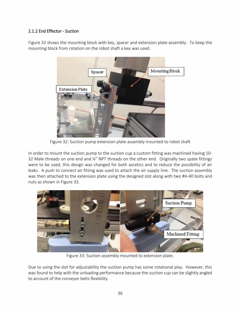
2.1.2 End Effector - Suction Figure 32 shows the mounting block with key, spacer and extension plate assembly. To keep the mounting block from rotation on the robot shaft a key was used.
Figure 32: Suction pump extension plate assembly mounted to robot shaft
In order to mount the suction pump to the suction cup a custom fitting was machined having 10-32 Male threads on one end and ¼” NPT threads on the other end. Originally two spate fittings were to be used, this design was changed for both ascetics and to reduce the possibility of air leaks. A push to connect air fitting was used to attach the air supply line. The suction assembly was then attached to the extension plate using the designed slot along with two #4-40 bolts and nuts as shown in Figure 33.
Figure 33: Suction assembly mounted to extension plate.
Due to using the slot for adjustability the suction pump has some rotational play. However, this was found to help with the unloading performance because the suction cup can be slightly angled to account of the conveyor belts flexibility.

37
2.1.3 Frame The fame for the enclosure was built for the design team by Parker Hannifin once the CAD prints were supplied. Figure 34 shows how the majority of the frames members are attracted together. This was done by drilling a hole into the IPS and inserting a “banjo” type connection (see figure x). One end of the “banjo” has a T shape that hooks into the T Slot of the IPS. Corner brackets were used below the robot mounting plate for extra support.
Figure 34: IPS “banjo” connection.
In order to make the furnace unloader mobile six casters were mounted to the frame. These casters were mounted using a 5/16” x 1” SHCS from the bottom and threaded into tapped hole in the IPS. A mounted caster can be seen in Figure 35. Originally, larger casters were used because they were more readily available; however, larger casters changed the height of the entire assembly requiring a longer extension plate. This increase in length made it impossible to place heat sinks into the box without hitting the box edges. Thus larger casters were replaced with the casters from the original design.

38
Figure 35: Caster mounted into tapped hole on frame.
The door of the enclosure was mounted using hinges made for use with IPS, as shown in Figure 36. Using snap in inserts that fit into the T slot of the IPS the hinge was mounted to the door frame and enclosure.
Figure 36: Hinge mounted to door and frame.
A slight modification was made to the frame design in order to securely mount the touchscreen
box. This was accomplished by adding two vertical 1.5 inch profile IPS members to the area above
the box opening. The placement of these members was determined by the bolt pattern on the
touchscreen box. The touchscreen box was then mounted using four 5/16 inch bolts and IPS
inserts, as seen in Figure 37.

39
Figure 37: Touch screen and box mounted to added vertical members.

40
2.1.4 Additional Subsystems
Over the course of the build process some modification and redesigns were done. The main design change from the original design was the heat sink alignment system or “funnel”. The original design made of IPS and HDPE plastic was changed because of the lack of adjustability and foreseen mounting issues. The new design consists of ½” thick Plexiglas sides that are bent and a slotted top cover for width adjustability. The funnel was then mounted using two hinges, allowing the funnel to be low enough for the laser sensors to accurately detect the heat sink, as seen in Figure 38.
Figure 38: Redesigned heat sink alignment system or “funnel.”
Cardboard boxes and inserts are needed to contain unloaded heat sinks. These boxes and cardboard need to be stored close to the unloader. Therefore, a shelf was designed to go under the robot mounting plate as seen in Figure 39.

41
Figure 39: Shelf added to design to hold cardboard box and insert.

42
2.2 Electrical Build Process
Figure 40 below shows the completed electrical box. The components within the enclosure include
5 fuse holders, a disconnect switch, power supply, safety relay, PLC, converter board, terminal
blocks, end terminals and wire duct. During the build process, several components had to be
added to the original design in order for it to work properly, starting with a voltage converter.
When the system first went into construction, the group was under the impression everything
could be powered by a wall source of 120VAC. It was not until further investigation that the team
realized the robot controller needed a supply of 200-230VAC.
Parker Hannifin supplied the design team with a drop down cord of 480VAC. This cable as seen in
Figure 40 (1) was routed into the electrical box, through a disconnect switch, and then back out of
the box. Its next destination was a transformer. The transformer used was a DRY 3 phase 6KVA
480V-208Y transformer with the part number of 6T2F. As the name suggests, this transformer
steps down the voltage to a safe voltage that can power the robot controller and the PLC which
can also be powered by 208VAC. The PLC used in the final design is the same as in the original
design. The team had no issues with the aged controller, so it was programmed and used as
needed. The mounted PLC can be seen in Figure 40 (2).
The programmable logic controller (PLC) handles the user inputs and sensor data in order to inform the robot arm controller which program to run. The PLC also informs the user of the status of the machine through indicator lights and a display. The digital I/O is 0V for OFF and 24V for ON. Starting on the far left of the chassis of the PLC is its power supply, followed by the PLC itself, and then various I/O cards which can include both digital and analog I/O along with specialty cards. Not all of the supplied I/O cards are used for this project, but all were left attached to the PLC. It has an RS232 serial communications port is used to interface with a display module. The 208VAC was also used to power a 1606-XLS power supply as seen in Figure 40 (3). This supply
was not the original power supply chosen for the system. The original power supply was a Sola
SDP brand, and when powered for the first time, it failed to output the 24VDC that was expected.
For this reason, the team found another 24V power supply (also recycled from Parker Hannifin)
and used it instead.

43
(1)
(2)
Figure 40: The panel layout located inside the electrical enclosure, where (1) is the main power
entry, (2) is the power supply, (3) is the PLC and (4) is the safety relay.
DNT12A terminal blocks were used to route and organize the various wires within the enclosure,
and based on the current ratings of the electrical components, proper fuses were selected and
installed into the system. The main fuse is a 25A fuse, and it is followed by all of the damageable
electronics. The PLC, power supply, robot controller, sensors, and touch screen are all protected
by individual fuses for circuit protection. The light curtains however, needed an extra safety
feature.
Originally the group decided to have all safety features in series with each other. It was not until
the installation of the pre-selected light curtains that the team realized the curtains required a
safety relay. The relay was added to the din rail within the enclosure, as seen in Figure 40 above
(4).
(3)
(4)

44
2.2.1 Controller – PLC, Robot Controller
Figure 41 shows the robot controller box. Ribbon cables connect to the I/O ports. The ribbon cables then connect to a converter board located on the lower right hand side of the electrical box. This converter board provides terminals to allow for larger gage wire to be connected to the I/O lines of the robot controller. The e-stop port is connected to the safety devices so that the controller is directly commanded to stop if any device is triggered. Each program is for a single plate position in the box. With four plates per layer and three layers per box, twelve programs were programmed into the controller.
Port 301 of the controller is an output that indicates whether or not the controller is ready to run a program. The controller indicates that it is ready by making port 301 go high. The ready signal is run to an input on the I/O input card of the PLC. Port 0 is an input port on the controller and it is used to tell the controller to start the program that has been selected. Port 0 and the program select ports (ports 8 through 14) will be connected to the I/O output card of the PLC so the PLC can select the program and then start the program once the ready signal has been received.
Figure 41: Front view of the robot controller.

45
2.2.2 Sensing – Plate Sensor A sensor is needed to communicate to the robot that a plate is present. The FSDK 109001/KS35 and FEDK 10P3101/KS35 Baumer Sensors (emitter and receiver), shown in Figure 42, can do just that. This Sensor combination is powered by a 24V DC supply and works in an opposed emitter/receiver configuration, with a range of 3m. The original sensors selected for this were much too bulky, and did not fit well with the funnel design. The group decided that these small, rectangular sensors would work just as efficiently, while adding aesthetic value to the design. In addition to this, Parker Hannifin supplied these sensors at no cost to the project. The schematic shows the connections needed for these Baumer sensors: BN is +24V supply, BU is common, WH is not connected, and BK is the signal. BK will go high (24V) when a plate crosses the beam and low (0V) when no plate is detected. These sensors are connected at the end of the funnel. They are mounted in place, so their relative location to the robotic arm is always the same. The sensors are located at the end of the guide and are triggered when the front of the traveling heat sink covers more than 50% of the emitter’s light. At this point, the machine knows the plate is present. The sensor sends a signal (through the BK conductor) to the PLC telling it that the plate is present, and the robot may now unload the plate.
Figure 42: FSDK 109001/KS35 and FEDK 10P3101/KS35 mounted on the end of the funnel.
46
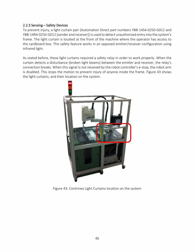
2.2.3 Sensing – Safety Devices To prevent injury, a light curtain pair (Automation Direct part numbers YBB-14S4-0250-G012 and YBB-14R4-0250-G012 [sender and receiver]) is used to detect unauthorized entry into the system’s frame. The light curtain is located at the front of the machine where the operator has access to the cardboard box. This safety feature works in an opposed emitter/receiver configuration using infrared light. As stated before, these light curtains required a safety relay in order to work properly. When the curtain detects a disturbance (broken light beams) between the emitter and receiver, the relay’s connection breaks. When this signal is not received by the robot controller’s e-stop, the robot arm is disabled. This stops the motion to prevent injury of anyone inside the frame. Figure 43 shows the light curtains, and their location on the system.
Figure 43: Contrinex Light Curtains location on the system

47
For safety reasons, it is important to have an emergency stop button available. Though the controller is already equipped with one, the placement of the control box will make the button difficult to access. The emergency stop button chosen is an OMRON A22E emergency stop button shown in Figure 44. This specific push button was chosen due to its affordability and ease of use. It is located on the top right corner of the display screen’s enclosure. The A22E series has a current rating of 10A and a voltage rating of 24V allowing the 24V signal to be routed through the button. This allows the signal to be removed from the robot controller's e-stop port when pressed, resulting in the cease of motion in the robotic arm.
Figure 44: Omron A22E emergency stop button installed on touch screen enclosure.

48
A magnetic sensor has been installed on the door of the enclosure. Parker has supplied the group with a Banner Engineering (Part Number: SI-MAG2SM W/30) magnetic sensor shown in Figure 45. The magnet must be within 3mm of the sensor to be detected. When the door is shut, the signal passes through the sensor, allowing the machine to function as normal. As soon as the door opens and the magnets are more than 3mm away from each other, the signal is broken and port 002 (E-Stop on Robot Controller) goes high. When this happens, the robot arm comes to an instant stop. Because the IPS used on the frame is much larger than 3mm, the door will never reach an open position without triggering the emergency stop. This is good, because it ensures that the intruder will not be harmed. The wires connected to these sensors are routed through the IPS of the frame.
Figure 45: Banner sensor (SI-MAG2SM W/30) used for open door sensing

49
2.2.4 Indicator Lights
A 3-color status indicator light, shown in Figure 46, is mounted on the front left corner of the frame. The three colors each have their own meaning, as seen in Table 2. This light was chosen for the original design, and worked as planned. The cable needed for the communication of the PLC to the light base fits well within the IPS of the structure. Table 2: Meaning of Indicator Light Colors and Required Operator Action.
Light Color Meaning Action Required
Green Unit is currently unloading heat sinks and running properly.
No action required.
Amber 3rd heat sink of current layer has been placed in box.
Operator must prepare to insert cardboard or change box.
Red Machine is stopped. 4th plate has been placed in current layer or emergency stop has been issued.
Operator intervention required.
Figure 46: The three color indicator light used to notify the operator of systems status.

50
2.2.5 Touchscreen Figures 47, 48, and 49 show the actual touch panel screens shown to the operator. The first screen, shown in figure 47, is displayed upon startup of the machine. The only purpose this screen serves is to introduce the machine. It consists of one button with “Begin!” as the label. When the operator presses this button, the screen is exited and the next screen is displayed.
Figure 47: Splash screen. First screen shown after startup. Introduces the machine.
The screen that is displayed next is the setup screen shown in figure 48. This screen provides
access to various machine parameters. This screen consists of three buttons and a number box.
The number box shows the plate that the machine is either currently waiting on or is currently
moving. The three buttons are labeled “Run Mode”, “Air Off”, and “Robot Home”. The “Robot
Home” button will cause the robot to return to its home position upon being pressed. This
button is useful after an emergency stop and is required to be pushed in order to clear the
emergency stop condition and continue unloading heat sinks. The “Air Off” button simply allows
the operator to disable the air flow to the suction cup. After an emergency stop the air is kept on
and this button must be pressed to turn the air off in order to remove any plate that may be still
in the suction cup.

51
Figure 48: Setup screen. Allows the operator access to various machine parameters.
The button labeled “Run Mode” exits the setup screen when pressed and loads the run screen shown in Figure 49. The run mode screen consists of a status display at the top of the window which displays various messages about the status of the machine. It also consists of three buttons labeled “Setup”, “Start”, and “Stop”. The “Start” button will activate the unloading process. Once pressed, the machine will wait for a plate to be detected by the plate sensor and then activate the robot to pick the plate up. When started, the “Setup” button will also disappear. When the “Stop” button is pressed, the machine will no longer react to a plate passing by the plate sensor and the “Setup” button will reappear. When an emergency stop is detected, the machine will be automatically stopped as if the “Stop” button was pressed and the machine will not be allowed to be started even if the “Start” button is pressed until a certain sequence has been completed to clear the emergency stop. The sequence that must be performed consists of going to the setup menu and pressing “Robot Home”. The button labeled “Setup” exits the run screen and loads the setup screen shown in Figure 48.
Figure 49: Run screen. Shows status information at top and provides a way for the operator to
start and stop the machine.

52
2.2.6 PLC Program Overview
The system consists of two controllers, the PLC acting as the central controller and the robot controller. The PLC is interfaced with the plate sensors, the robot controller, the light stack, and the touch screen. See Figure 50 for the PLC program flow chart. The main difference between the original final design and the current design is requiring the operator to home the robot after an e-stop. The PLC will command the robot controller by addressing the program number in binary coded decimal on the robot controller program number input lines. It will then command the robot controller to start the program by asserting the signal on the program start input line of the robot controller. All emergency stop devices are connected directly to the robot controller’s external e-stop port. When an emergency stop device is activated, the robot controller is the first to know about it and will immediately stop the robot arm. The robot control will then issue a notification on its e-stop status output so that controllers within the system can know that an e-stop has occurred and react appropriately. When an e-stop is reported to the PLC, the PLC will put the machine in stop mode and not allow the operator to restart the machine until the robot has been homed. When the PLC is in start mode, it will wait for a plate to be detected by the IR sensor on the funnel. Once a detection has occurred, the PLC will command the robot to run the program that corresponds to the current plate number. The PLC has two ways to notify the operator of its status. The first way is through the light stack on the top of the machine and the second is through a message box on the touch screen. The PLC will let the operator know which plate is currently being waited on or unloaded, if cardboard must be added to the box, if the box must be changed, and if there is an emergency stop that has been detected.

53
Figure 50: Flow chart of machine operation.

54
Robot Program Overview Figure 51 shows a basic flowchart for the program that will run on the robot controller. Like the PLC controller, the robot controller will constantly be checking for an E-stop status. Whenever an E-stop is in effect, the system will shut down, causing the robot arm to immediately stop all motion. When everything is working properly, the robot controller will send a signal to the PLC letting the PLC know that it is ready to unload a heat sink. The PLC will then send a signal back to the robot when the plate sensor detects a plate. The signal sent from the PLC will tell the robot controller (through ports 8-14) exactly what program to run. The PLC will have 12 different programs to choose from based on which plate is being unloaded. After the plate has been unloaded, the robot will once again wait for the ready signal.
Figure 51: Flow chart of robot operation.

55
Software Environments and Programming Languages Used Three different software environments were used to program the machine. A different environment is required for the PLC, Robot controller, and the touch panel. The PLC required the software program “RSLogix 500” which is a software programming environment that utilizes ladder logic as the programming language for the PLC. The robot controller utilized “IHSEL for Windows” which is a software programming environment that utilizes the SEL (Sensor Effector Language) for programming the robot. The touch screen required the use of a software program called “Interact” which is a software environment that provides a graphical means of designing the panels for the touch screen. There are some challenges that this software presented during the build process. The major challenge is the fact that it is older software designed to be used on older computer systems. “RSLogix 500” and “Interact” must both be used with Windows XP. “IHSEL for Windows” must be used with Windows 98 to operate properly. The outdated computers used to program the various components tended to crash often causing delays in the build process. The other challenge with working with older software is that there is minimal support for it which means any problems that occur likely have to be resolved by the group which leads to lost time.

56
Electrical Schematic
Figure 52: Final electrical schematic generated in AutoCAD Electrical.

57
Overview of Electrical Box
Figure 53: Final panel layout of electrical box generated in AutoCAD Electrical.

58
Figure 54: Physical layout of electrical box.

59
2.3 Project Cost
In the original design, the estimated cost of the prototype was $2256.35. After the building process
was complete, all the material costs were added up in a bill of materials, as shown in Table 3. The
final cost of the prototype was $4260.69. The additional $2000 spent was due to unforeseen costs
in debugging problems with the programming and additional electronic components that were
not taken into account. The final cost of the prototype is still less than the $5000 dollars budgeted
in the project statement.

60
Table 3: Bill of Materials

61
Section 3: Testing

62
In order to evaluate and confirm that the furnace unloader meets all the requirements and specifications, certain tests are written and performed to measure key quantities. The quantities measured have certain values that indicate that the device can meet the specifications. Table 4 outlines these quantities that are to be measured according to the following procedures and compared to their respective specifications.
Table 4: Measured Parameters Information Measured Parameter
Description Sample
Size
Unload Cycle Time
The time it takes for the system to detect and unload a heat sink into the box, return to the unload position, and be ready to detect and unload the
next heat sink 12
Maximum Suction Load
The load that the suction cup can successfully lift vertically with an 80 PSI air supply
1
Placement Accuracy
The linear distance variation of placement of a heat sink along the length of the box that occurs for heat sinks in the same position after 6
placements 6
E-Stop Time The time between issue of E-stop / light curtains and when the robot
motion ceases 6
Live Door Gap The linear distance between the enclosure frame and the door when E-
Stop is activated from door sensor 6
Unload Success Proportion
The proportion of heat sinks successfully unloaded for a single box 12
Correct Status Indication Proportion
The proportion of correct statuses given by status indicators (light indicators and touchscreen GUI) for a single box
1
System Enclosure
Displacement Displacement of the entire enclosure frame after unloading 12 heat sinks 1
It is proposed to measure these quantities with the following tests. These tests were constructed so that the quantities to be measured could be measured in the least amount of tests.

63
Test 1
Quantities to measure
1. Unload Cycle Time 2. Unload Success Proportion 3. Correct Status Indication Proportion 4. System Enclosure Displacement
Equipment 1. Stopwatch 2. Tape measure 3. Electrical or masking tape
Procedure
1. Prepare a run of 12 heat sinks. 2. Ensure the system is powered up. Prepare system for unloading. 3. Mark the locations of the four casters with tape as shown in Figure X. 4. Start the run of heat sinks down the conveyor belt. 5. Start stopwatch when the first heat sink is detected and the unloading
cycle begins. 6. Stop stopwatch when the robot returns to the ready position. Record
time and reset stopwatch. 7. Repeat steps 5 and 6 for each heat sink in the run. 8. During run, count number of heat sinks that are successfully unloaded
and record. 9. During run, count correct status indications at both light indicators and
touchscreen during key steps of the unloading process and record. 10. After full run is complete, measure displacement of casters relative to
the marking tape with tape measure. Record four distances.
Test 2 Quantities to measure 1. Maximum Suction Load
Equipment 1. Scale 2. 10 lb weight or four heat sinks 3. Tape 4. Suction assembly with 80 PSI air supply
Procedure 1. Use 10 lb weight or tape together four heat sinks (about 10 lbs). 2. Connect suction pump to 80 PSI air supply. 3. Turn on air and apply suction cup to weight or heat sinks. 4. Lift the suction cup assembly vertically and hold for 10 seconds in the air. 5. If suction pump can successfully hold the weight, record a pass. 6. Repeat 6 times.

64
Test 3 Quantities to measure 1. Placement Repeatability
Equipment 1. Permanent marker 2. Tape measure or calipers
Procedure
1. Place heat sink in unload position. Initiate unload. 2. Use marker to mark the placement of the heat sink in the box. 3. Reset program to unload heat sink #1 again. 4. Repeat steps 1 through 3 eleven more times. 5. Use calipers or tape measure to measure the variation from the initial
placement as indicated by the marker. Record distance. 6. Report maximum variation.
Test 4
Quantities to measure 1. E-Stop Time 2. Live Door Gap
Equipment 1. Stopwatch 2. Tape measure or calipers
Procedure
1. Initiate an unload process and activate E-stop while robot is moving. Start stopwatch.
2. Stop stopwatch when robot stops moving. Record time. 3. Repeat steps 2 and 3 five more times with the E-stop. 4. Repeat steps 2 and 3 six times with the light curtains. 5. Monitor the PLC inputs while opening door. When door sensor is
activated, measure the distance between the enclosure frame and the door, i.e. the gap between the open door and the frame. If there is no gap, record 0 inches.

65
Table 5 shows the measured quantities along with the specification to pass the tests. All quantities pass the tests. It should be noted that the initial specification for placement repeatability (0.1 inches) would fail the test. However, this specification is flawed. Initially, it was thought that 5 heat sinks would be placed horizontally for each layer of the box. However, because of the safety weight limit of the box, it was easier to only put 4 heat sinks horizontally in each layer. This made for 3 layers of 4 heat sinks, which would fill the box to the maximum weight for safe lifting. This also made the tight accuracy for placement more relaxed. If the same logic used to create the 0.1 inch accuracy spec for 5 heat sinks is used for 4 heat sinks, the specification for accuracy/repeatability is 0.4 inches. Then, the measured placement accuracy passes.
Table 5: Measured Quantities
Test # Quantity Specification
Measured Pass/Fail Condition Value Unit
1 Unload Cycle Time ≤ 40 sec 10 Pass
2 Max Suction Load ≥ 4 lbf 4.26 Pass
3 Placement Repeatability < 0.4 inch 0.25 Pass
4 E-Stop Time < 1 sec 0 Pass
4 Live Door Gap = 0 inch 0 Pass
1 Unload Success Proportion = 100% 100% Pass
1 Correct Status Indication Proportion = 100% 100% Pass
1 System Enclosure Displacement < 1.25 inch 0 Pass

66
Section 4: Evaluation and Recommendations

67
4.1 Evaluation The following list outlines the requirements and specifications set by Parker and the design team at the beginning of the project. It also shows how the final design prototype and the tests performed on it demonstrate that the requirements and specifications are met.
The device must unload heat sinks from the production line without causing defects. An
unloading failure is defined by (1) a fall of a heat sink to the floor or (2) a scratch or gouge
0.015” deep incurred by the heat sink.
o The device successfully unloads heat sinks.
o No falls have been observed.
o Only soft silicone material touches the heat sink during unloading.
o No scratches have been observed.
The device must load heat sinks into a specified box with accuracy of placement within 0.1”. This criterion was made based on the fact that five heat sinks are placed in the box without an interference.
o This specification was valid for 5 heat sinks placed horizontally along the length of the box for each layer. However, only 4 heat sinks will be placed horizontally for each layer.
o A new specification for 4 heat sinks was calculated to be 0.4 inches. o The measured variation in the heat sink placement is 0.25 inches. o No heat sink interferences have been observed in the box.
After an unloading operation, the device must be capable of returning to its home position in 40 seconds. The time corresponded to a minimized travel time for the next heat sink to arrive in the unload position. The fastest belt speed of 12.3 in/min was used to come up with a conservative estimation.
o The device unloads heat sinks and returns to its home position in 10 seconds on average.
o The device has been observed to always be ready to pick up the next heat sink.
The device must automate the placement of cardboard in the box or alert the operator to do so.
o The device successfully alerts the operator to load cardboard with a red light.
The device must automate the storing away of boxes in order for more boxes to be loaded or alert the operator to do so.
o The device successfully alerts the operator to store box with a red light.
The device must be able to be toggled on and off. The main reason for this requirement is that dunnage, or dummy heat sinks, must run through the furnace before and after the production line of heat sinks to stabilize the temperature in the furnace. The dunnage should not be unloaded and is allowed to fall off of the conveyor at the end of the line into a bucket.
o The device has a button on the touchscreen to stop the unloading process.
The device must be portable so that Parker engineers can move the device to a different conveyor belt if needed.

68
o The entire device rests on 6 casters that allow it to move around the factory floor.
The device must be safe to the operator and environment. o Many items are included in the design to provide safety. o Plexiglas does not allow for reaching inside unloading area. o Hinged door and opening for box include sensors that disable the machine when
someone is reaching inside the enclosure. o All high voltage signals are enclosed in electrical box. o No pinch points are accessible. o Readily available emergency stops located around the enclosure.

69
4.2 Recommendations
1. It is recommended to employ a larger suction cup, so that the fitting that connects the pump to the suction cup has a larger diameter.
2. For more flexibility in picking up different sized heat sinks, it is recommended to employ a robot with a larger range of vertical motion.
3. It is recommended to update robot program to enable it to also pick up cardboard and load the cardboard into the box when necessary. It is feasible to do this since the robot can move in other locations besides the unloading position and the box. A location would need to be specified where the cardboard would be picked up.

70
Conclusions

71
Conclusions
1. The prototype meets all requirements and specifications as proven by the testing completed.
2. The device successfully reduces operator time by relieving him of the time-consuming task of unloading all heat sinks.
3. Safety of the unloading operation has increased, because never has to come into contact with the hot heat sinks.
4. An initial prototype has been designed with a modular frame, which can be easily reassembled in other form factors to enable modifications for other conveyor belts and other heat sinks or parts at Parker Hannifin.

72
References

73
Banner Engineering Corporation. Web. Accessed 3 December 2013. <http://www.bannerengineering.com/image.php?i=magnet-style_Family::Web>.
Budynas, Richard G., J. Keith Nisbett. Shigley’s Mechanical Engineering Design. McGraw-Hill
2011. eBay.com. Web. Accessed 3 December 2013. <http://thumbs1.ebaystatic.com/d/l225/m/mRJEKocWiRQQNnti8s8rAiw.jpg>. eCrater.com. Web. Accessed 3 December 2013. <http://s.ecrater.com/stores/253253/4fcea8fc431ab_253253n.jpg>. Factory Controls. Web. Accessed 3 December 2013.
<http://www.factorycontrols.com.au/images/products/safety-components/3.safety_sensors/f3sj.jpg>.
Intelligent Actuator, Inc. Super SEL Controller IH Type Operating Manual. May, 1998. Newark.com. Web. Accessed 3 December 2013.
<http://www.newark.com/productimages/standard/en_US/4422273.jpg>. Octopart.com. Web. Accessed 3 December 2013.
<http://sigma.octopart.com/12081344/image/Banner-SM31RQD.jpg>. Octopart.com. Web. Accessed 3 December 2013. <http://sigma.octopart.com/9895516/image/Omron-A22E-M-11.jpg>. Octopart.com. Web. Accessed 3 December 2013. <http://sigma.octopart.com/11314443/image/Sola-SDP4-24-100LT.jpg>. ONExia, Inc. “IH-SCARA Robot series model IH-500-150.” Web. Accessed 15 October 2013.
<onexia.com/pdf/IAIscara.pdf>. Thai Advance Electric Sales & Services Co., Ltd. Web. Accessed 3 December 2013.
<http://taeco.co.th/images/products/items/4_image015.png>.

74
Appendices

75
Appendix A – Drawings

76

77

78

79

80

81

82

83

84
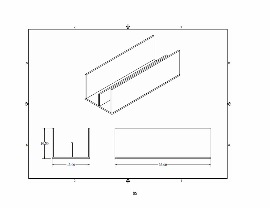
85

86

87

88
Robot Programs Prog = 01 BTOF303 ready off SVON1111 turn on servos VEL 30 MOVP1 home pos up BTOF302 air on MOVP2 home pos down TIMW1 wait for vacuum MOVP3 home pos up MOVP4 to box home MOVP6 to pos 1 up MOVP7 pos 1 down BTON302 air off TIMW1 wait for drop MOVP8 pos 1 up MOVP4 to box home BTON304 TIMW0.1 BTOF304 BTON303 ready on EXIT Prog = 02 BTOF303 ready off SVON1111 turn on servos VEL 30 MOVP1 home pos up BTOF302 air on MOVP2 home pos down TIMW1 wait for vacuum MOVP3 home pos up MOVP4 to box home MOVP10 to pos 2 up MOVP11 pos 2 down BTON302 air off TIMW1 wait for drop MOVP12 pos 2 up MOVP4 to box home BTON304 TIMW0.1 BTOF304 BTON303 ready on EXIT

89
Prog = 03 BTOF303 ready off SVON1111 turn on servos VEL 30 MOVP1 home pos up BTOF302 air on MOVP2 home pos down TIMW1 wait for vacuum MOVP3 home pos up MOVP4 to box home MOVP14 to pos 3 up MOVP15 pos 3 down BTON302 air off TIMW1 wait for drop MOVP16 pos 3 up MOVP4 to box home BTON304 TIMW0.1 BTOF304 BTON303 ready on EXIT Prog = 04 BTOF303 ready off SVON1111 turn on servos VEL 30 MOVP1 home pos up BTOF302 air on MOVP2 home pos down TIMW1 wait for vacuum MOVP3 home pos up MOVP4 to box home MOVP18 to pos 4 up MOVP19 pos 4 down BTON302 air off TIMW1 wait for drop MOVP20 pos 4 up MOVP4 to box home BTON304 TIMW0.1 BTOF304 BTON303 ready on EXIT Prog = 05 BTOF303 ready off

90
SVON1111 turn on servos VEL 30 MOVP1 home pos up BTOF302 air on MOVP2 home pos down TIMW1 wait for vacuum MOVP3 home pos up MOVP4 to box home MOVP6 to pos 5 up MOVP7 pos 5 down BTON302 air off TIMW1 wait for drop MOVP8 pos 5 up MOVP4 to box home BTON304 TIMW0.1 BTOF304 BTON303 ready on EXIT Prog = 06 BTOF303 ready off SVON1111 turn on servos VEL 30 MOVP1 home pos up BTOF302 air on MOVP2 home pos down TIMW1 wait for vacuum MOVP3 home pos up MOVP4 to box home MOVP10 to pos 6 up MOVP11 pos 6 down BTON302 air off TIMW1 wait for drop MOVP12 pos 6 up MOVP4 to box home BTON304 TIMW0.1 BTOF304 BTON303 ready on EXIT Prog = 07 BTOF303 ready off SVON1111 turn on servos VEL 30

91
MOVP1 home pos up BTOF302 air on MOVP2 home pos down TIMW1 wait for vacuum MOVP3 home pos up MOVP4 to box home MOVP14 to pos 7 up MOVP15 pos 7 down BTON302 air off TIMW1 wait for drop MOVP16 pos 7 up MOVP4 to box home BTON304 TIMW0.1 BTOF304 BTON303 ready on EXIT Prog = 08 BTOF303 ready off SVON1111 turn on servos VEL 30 MOVP1 home pos up BTOF302 air on MOVP2 home pos down TIMW1 wait for vacuum MOVP3 home pos up MOVP4 to box home MOVP18 to pos 8 up MOVP19 pos 8 down BTON302 air off TIMW1 wait for drop MOVP20 pos 8 up MOVP4 to box home BTON304 TIMW0.1 BTOF304 BTON303 ready on EXIT Prog = 09 BTOF303 ready off SVON1111 turn on servos VEL 30 MOVP1 home pos up BTOF302 air on

92
MOVP2 home pos down TIMW1 wait for vacuum MOVP3 home pos up MOVP4 to box home MOVP22 to pos 9 up MOVP23 pos 9 down BTON302 air off TIMW1 wait for drop MOVP24 pos 9 up MOVP4 to box home BTON304 TIMW0.1 BTOF304 BTON303 ready on EXIT Prog = 10 BTOF303 ready off SVON1111 turn on servos VEL 30 MOVP1 home pos up BTOF302 air on MOVP2 home pos down TIMW1 wait for vacuum MOVP3 home pos up MOVP4 to box home MOVP26 to pos 10 up MOVP27 pos 10 down BTON302 air off TIMW1 wait for drop MOVP28 pos 10 up MOVP4 to box home BTON304 TIMW0.1 BTOF304 BTON303 ready on EXIT Prog = 11 BTOF303 ready off SVON1111 turn on servos VEL 30 MOVP1 home pos up BTOF302 air on MOVP2 home pos down TIMW1 wait for vacuum

93
MOVP3 home pos up MOVP4 to box home MOVP30 to pos 11 up MOVP31 pos 11 down BTON302 air off TIMW1 wait for drop MOVP32 pos 11 up MOVP4 to box home BTON304 TIMW0.1 BTOF304 BTON303 ready on EXIT Prog = 12 BTOF303 ready off SVON1111 turn on servos VEL 30 MOVP1 home pos up BTOF302 air on MOVP2 home pos down TIMW1 wait for vacuum MOVP3 home pos up MOVP4 to box home MOVP34 to pos 12 up MOVP35 pos 12 down BTON302 air off TIMW1 wait for drop MOVP36 pos 12 up MOVP4 to box home BTON304 TIMW0.1 BTOF304 BTON303 ready on EXIT Prog = 13 SVON1111 MOVP39 move z up MOVP40 go to box home EXIT Prog = 63 BTON303 ready on EXIT Prog = 64 BTON303 ready on

94
EXIT

95
Robot Points
1 F 25 247.707 434.166 0.000 -47.950 2 F 50 247.707 434.166 151.000 -47.950 3 F 50 247.707 434.166 0.000 -47.950 4 F 25 -112.038 298.080 0.500 -50.300 6 F 25 -166.482 207.935 0.000 -55.720 7 F 50 -166.482 207.935 150.000 -55.720 8 F 50 -166.482 207.935 0.000 -55.720 10 F 25 -201.511 187.901 0.000 -68.100 11 F 50 -201.513 187.909 150.000 -68.100 12 F 50 -201.513 187.909 0.000 -68.100 14 F 25 -236.323 180.815 0.003 -80.000 15 F 50 -236.323 180.815 150.000 -80.000 16 F 50 -236.323 180.815 0.000 -80.000 18 F 25 -283.267 200.483 0.000 -88.700 19 F 50 -283.266 200.476 150.000 -88.700 20 F 50 -283.266 200.476 0.000 -88.700 22 F 25 -166.482 207.935 0.000 -55.720 23 F 50 -166.482 207.935 130.000 -55.720 24 F 50 -166.482 207.935 0.000 -55.720 26 F 25 -201.511 187.901 0.000 -68.100 27 F 50 -201.513 187.909 130.000 -68.100 28 F 50 -201.513 187.909 0.000 -68.100 30 F 25 -236.323 180.815 0.003 -80.000 31 F 50 -236.323 180.815 130.000 -80.000 32 F 50 -236.323 180.815 0.000 -80.000 34 F 25 -283.267 200.483 0.000 -88.700 35 F 50 -283.266 200.476 130.000 -88.700 36 F 50 -283.266 200.476 0.000 -88.700 39 4 1 0.000 40 F 1 -112.038 298.080 0.500 -50.300

96
PLC Program Screenshots

97

98

99