ENGLISH Do(Digital Output) Kit - lg-b2b.ru Блоки...
13
ENGLISH LG Do(Digital Output) Kit INSTALLATION MANUAL LG IMPORTANT • Please read this installation manual completely before installing the product. • Installation work must be performed in accordance with the national wiring standards by authorized personnel only. • Please retain this installation manual for future reference after reading it thoroughly. Visit us at : http://www.lgservice.com Models: PQNFP00T0 ITALIANO ESPAÑOL FRANÇAIS DEUTSCH CHINESE
Transcript of ENGLISH Do(Digital Output) Kit - lg-b2b.ru Блоки...

ENG
LISHLGDo(Digital Output) Kit INSTALLATION MANUAL
LG
IMPORTANT
• Please read this installation manual completely before installing the product.
• Installation work must be performed in accordance with the national wiring standards by authorized personnel only.
• Please retain this installation manual for future reference after reading it thoroughly.
Visit us at : http://www.lgservice.com
Models: PQNFP00T0
ITALIA
NO
ESPAÑ
OL
FRA
NÇ
AIS
DEU
TSCH
CH
INESE

2 Do kit
Do Kit INSTALLATION MANUAL
TABLE OF CONTENTS
� Safety Precautions.........................................................3~4
� Acceassory Parts ..............................................................5
� Components.......................................................................6
� How to set ....................................................................7~11
� Procedure to install ....................................................................................7
� Wiring diagram...........................................................................................8
� How to inspect .........................................................................................11

ENG
LISHSafety Precautions
Installation Manual 3
Don't touch with thehands while the power ison
• There is risk of fire or electricshock.
Use standardparts(connector).
• Do not disassemble or repairthe product. There is risk of fireor electric shock.
For electrical work, contactthe dealer, seller, a qualifiedelectrician, or an AuthorizedService Center.
• Do not disassemble or repairthe product. There is risk of fireor electric shock.
� Installation
Safety PrecautionsTo prevent injury to the user or other people and property damage, the following instructionsmust be followed.� Incorrect operation due to ignoring instruction will cause harm or damage. The seriousness is
classified by the following indications.
� Meanings of symbols used in this manual are as shown below.
WARNING
CAUTION
This symbol indicates the possibility of death or serious injury.
This symbol indicates the possibility of injury or damage.
Be sure not to do.
Be sure to follow the instruction.
WARNING

Safety Precautions
4 Do kit
When the product is soaked (flooded orsubmerged), contact an Authorized ServiceCenter.• There is risk of fire or electric shock.
Be cautious that water could not enter theproduct.
• There is risk of fire, electric shock, or productdamage.
� Operation
Use the correctly ratedbreaker or fuse.
• There is risk of fire or electricshock.
Do not install, remove, or re-install the unit by yourself(customer).
• There is risk of fire, electricshock, explosion, or injury.
For installation, alwayscontact the dealer or anAuthorized Service Center.
• There is risk of fire, electric
shock, explosion, or injury.

ENG
LISHAcceassory Parts
Installation Manual 5
Acceassory Parts
Connection Cable (AWG18*5EA) Additional Connection Cable
Do Kit : 6871A90053D Front case
POWER RELAY (G7L-2A-TUB) Connection Terminal
Installation Manual
CON_COMM
CN_POWER
Relay OUT
Do Kit
1 2 3 4
CN_COMM
CN_POWER
* Others: Tie wrap for arranging the cable -2EA

SW2: Function setting DIP switch
SW1: Reset switch
BUS_A: 485 communication BUS_A
BUS_B: 485 communication BUS_B
LD4: 485 communication LED
CON_SW: Relay output
CN_POWER: 220V power
SW_HIGH: Group address setting rotary switch
LD2: Relay status LED
SW_LOW: Indoor unit address setting rotary switch
Components
Components
6 Do kit
1 2 3 4
CN_COMM
CN_POWER
A
C
B
155mm
155m
m
235mm
A. DO KIT
B. POWER RELAY C. CONNECTING TERMINAL
1
0
8
Power RelaySPEC: COIL: 200-240VAC25A, 240V ~cos ø125A, 240V ~cos ø0.4
6
4
2
A:AC220V(L)B :AC220V(N)

How to set
Installation Manual 7
ENG
LISH
How to setProcedure to install
1. Use and rotary switch to set the central control address.
2. Connect the relay output at to the power relay.
3. Connect BUS_A at and BUS_B at to the BUS_A and the BUS_B of the CNU or ACP respectively.
4. Set according to the relay ON/OFF function of the DIP switch at .
1 2 3 4
CN_COMM
CN_POWER
3 F 0123
456789A
B
CDEF
0123
456789A
B
CDEF
Ex) For setting "3F"
Group No (SW-HIGH)
Indoor No(SW-LOW)
Indoor unit No
Group No
The above figure shows the initial relay turned off and the 3-minute delay disabled.
5. Apply the 220V power to .
• No. 1 S/W ON : The initial relay is turned on when thepower is applied to the contact PI-485
• No. 1 S/W OFF : The initial relay is turned off when thepower is applied to the contact PI-485
• No. 2 S/W : Set to OFF
• No. 3 S/W ON : The 3-minute delay is disabled when therelay is turned on/off.
• No. 3 S/W OFF : The 3-minute delay is enabled when therelay is turned on/off.
• No. 4 S/W : Set to ON
1
ON
2 3 4

How to set
8 Do kit
Wiring diagramWhen the product input is less than or equal to 25A(The air conditioner is controlled by turning on/off the power supply line of the product.)
1 2 3 4
CN_COMM
CN_POWER
ACP Controller
BUS_A
BUS_B
AC input power(220V, 60Hz)
L N
Breaker or Power
Outdoor unit Indoor unit
Wiring the earth line
1. Pull out the power or shutdown the breaker.
2. Connect the power linefrom the breaker to theadditional relay cable.
3. Connect to the outdoorunit power line and theadditional relay cable.
4. Finish the connected areawith the insulating tape.
• All central controllers using the LGAP protocol except the ACP can be used.
Central control signal Do kit Product
Run Contact ON (Relay ON) Product power ON (possible to be controlled by the indoorunit)
Stop Contact OFF (Relay OFF) Product power OFF
Note: • Connecting the communication terminal (BUS_A, BUS_B) and the power terminal
(L, N) reversely may damage the product.
• The model with the indoor/outdoor unit communicating the RS485 or other data bythe above connection may cause the failure.
• When the power specification connecting to the relay is higher than the specificationof the supplied relay, use the separate relay.

How to set
Installation Manual 9
ENG
LISH
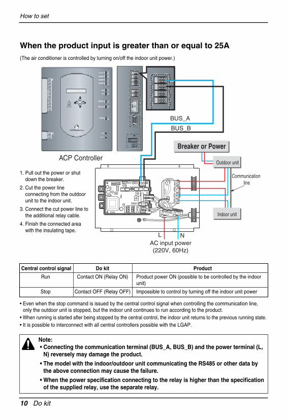
When the product input is greater than or equal to 25A(The air conditioner is controlled by turning on/off the indoor/outdoor communication line.)
1 2 3 4
CN_COMM
CN_POWER
ACP Controller
BUS_A
BUS_B
AC input power(220V, 60Hz)
L N
Breaker or Power
Communication line
Power line
Outdoor unit
Indoor unit
1. Pull out the power or shutdown the breaker.
2. Cut the indoor/outdoor unitcommunication line.
3. Connect the cutcommunication line to theadditional relay cable asshown at the figure.
4. Finish the connected area withthe insulating tape.
• Even when the stop command is issued by the central control signal when controlling the communication line,only the outdoor unit is stopped, but the indoor unit continues to run according to the product.
• When running is started after being stopped by the central control, the indoor unit returns to the previous running state.• It is possible to interconnect with all central controllers possible with the LGAP.
Central control signal Do kit Product
Run Contact ON (Relay ON) Product power ON (possible to be controlled by the indoorunit)
Stop Contact OFF (Relay OFF) Product power OFF
Note: • Connecting the communication terminal (BUS_A, BUS_B) and the power terminal
(L, N) reversely may damage the product.
• The model with the indoor/outdoor unit communicating the RS485 or other data bythe above connection may cause the failure.
• When the power specification connecting to the relay is higher than the specificationof the supplied relay, use the separate relay.
How to set
10 Do kit
When the product input is greater than or equal to 25A(The air conditioner is controlled by turning on/off the indoor unit power.)
1 2 3 4
CN_COMM
CN_POWER
ACP Controller
BUS_A
BUS_B
AC input power(220V, 60Hz)
L N
Breaker or Power
Communication line
Indoor unit
Outdoor unit
1. Pull out the power or shutdown the breaker.
2. Cut the power lineconnecting from the outdoorunit to the indoor unit.
3. Connect the cut power line tothe additional relay cable.
4. Finish the connected areawith the insulating tape.
• Even when the stop command is issued by the central control signal when controlling the communication line,only the outdoor unit is stopped, but the indoor unit continues to run according to the product.
• When running is started after being stopped by the central control, the indoor unit returns to the previous running state.• It is possible to interconnect with all central controllers possible with the LGAP.
Central control signal Do kit Product
Run Contact ON (Relay ON) Product power ON (possible to be controlled by the indoorunit)
Stop Contact OFF (Relay OFF) Impossible to control by turning off the indoor unit power
Note: • Connecting the communication terminal (BUS_A, BUS_B) and the power terminal (L,
N) reversely may damage the product.
• The model with the indoor/outdoor unit communicating the RS485 or other data bythe above connection may cause the failure.
• When the power specification connecting to the relay is higher than the specificationof the supplied relay, use the separate relay.

How to set
Installation Manual 11
ENG
LISH
How to inspect
1. How to make sure that the central control is normally connected• Make sure that the LD4 periodically blinks.• If the LD4 does not periodically blink, make sure that the DIP switch and the rotary switch (address setting)
are correct.• Make sure that the BusA and the BusB line are correctly connected.
2. How to make sure that the relay is turned on/off• If the relay is turned on, the LD2 is turned on.
• If the relay is turned off, the LD2 is turned off.
1 2 3 4
CN_COMM
CN_POWER
LD4 : 485 communication LED LD2 : Relay status LED

Memo
12 Do kit

P/No.: MFL58136507After reading this manual, keep it in a place easily accessible to the user for future reference.
Printed in Korea