ENGINEERING SYMBOLOGY, PRINTS, AND DRAWINGS Textbooks/08... · Anatomy of a Drawing ... TPC...
27
ENGINEERING SYMBOLOGY, PRINTS, AND DRAWINGS Module 1 Introduction to Print Reading
Transcript of ENGINEERING SYMBOLOGY, PRINTS, AND DRAWINGS Textbooks/08... · Anatomy of a Drawing ... TPC...

ENGINEERING SYMBOLOGY, PRINTS, AND DRAWINGS
Module 1
Introduction to Print Reading

Engineering Symbology, Prints, & Drawings Intro to Print Reading
ii
TABLE OF CONTENTS
Table of Co nte nts TABLE OF CONTENTS .............................................................................................................. ii
LIST OF FIGURES .................................................................................................................... iii
LIST OF TABLES ....................................................................................................................... iv
REFERENCES ........................................................................................................................... v
OBJECTIVES............................................................................................................................. vi
INTRODUCTION TO PRINT READING ......................................................................................1
Introduction..............................................................................................................................1
Anatomy of a Drawing .............................................................................................................2
The Title Block .........................................................................................................................2
Grid System.............................................................................................................................5
Revision Block .........................................................................................................................6
Changes ..................................................................................................................................7
Notes and Legend ...................................................................................................................8
Summary .................................................................................................................................9
INTRODUCTION TO THE TYPES OF DRAWINGS, VIEWS, AND PERSPECTIVES ...............10
Categories of Drawings .........................................................................................................10
Piping and Instrument Drawings (P&IDs) ...............................................................................10
Electrical Single Lines and Schematics .................................................................................11
Electronic Diagrams and Schematics ....................................................................................13
Logic Diagrams and Prints .....................................................................................................14
Fabrication, Construction, and Architectural Drawings ...........................................................14
Drawing Format .....................................................................................................................16
Views and Perspectives ........................................................................................................19
Summary ...............................................................................................................................21

Engineering Symbology, Prints, & Drawings Intro to Print Reading
iii
LIST OF FIGURES
Figure 1 Title Block ................................................................................................................... 3
Figure 2 Example of a Grid ....................................................................................................... 5
Figure 3 Revision Block ............................................................................................................ 6
Figure 4 Methods of Denoting Changes .................................................................................... 7
Figure 5 Notes and Legends ..................................................................................................... 8
Figure6 Example P&ID ............................................................................................................ 10
Figure 7 Example of a Single Line .......................................................................................... 11
Figure 8 Example of a Schematic ............................................................................................ 12
Figure 9 Example of an Electronic Diagram ........................................................................... 13
Figure 10 Example of a Logic Print ......................................................................................... 14
Figure 11 Example of a Fabrication Drawing ........................................................................... 15
Figure 12 Example of a Single Line P&ID ............................................................................... 16
Figure 13 Example Pictorial .................................................................................................... 17
Figure 14 Example of an Assembly Drawing ........................................................................... 17
Figure 15 Example of a Cutaway ............................................................................................ 18
Figure 16 Example Orthographic Projection ............................................................................ 19
Figure 17 Orthographic Projections ......................................................................................... 20
Figure 18 Example of an Isometric .......................................................................................... 20

Engineering Symbology, Prints, & Drawings Intro to Print Reading
iv
LIST OF TABLES
NONE

Engineering Symbology, Prints, & Drawings Intro to Print Reading
v
REFERENCES
ASME Y14.5-2009, Dimensioning and Tolerancing
IEEE Std 315-1975 (Reaffirmed 1993), Graphic Symbols for Electrical and Electronic
Diagrams
Gasperini, Richard E., Digital Troubleshooting, Movonics Company; Los Altos,
California, 1976.
Jensen - Helsel, Engineering Drawing and Design, 7th Ed., McGraw-Hill Book
Company, New York (August 15, 2007)
Lenk, John D., Handbook of Logic Circuits, Reston Publishing Company, Reston,
Virginia, 1972.
Wickes, William E., Logic Design with Integrated Circuits, John Wiley & Sons, Inc,
1968.
Naval Auxiliary Machinery, United States Naval Institute, Annapolis, Maryland, 1951.
TPC Training Systems, Reading Schematics and Symbols, Technical Publishing
Company, Barrington, Illinois, 1974.
Arnell, Alvin, Standard Graphical Symbols, McGraw-Hill Book Company, 1963.
George Masche, Systems Summary of a Westinghouse Pressurized Water Reactor,
Westinghouse Electric Corporation, 1971.
Smith-Zappe, Valve Selection Handbook, 5th Ed., Gulf Publishing Company, Houston,
Texas, December 2003.

Engineering Symbology, Prints, & Drawings Intro to Print Reading
vi
OBJECTIVES
TERMINAL OBJECTIVE
1.0 Given an engineering print, READ and INTERPRET the information contained in the title
block, the notes and legend, the revision block, and the drawing grid.
ENABLING OBJECTIVES
1.1 STATE the five types of information provided in the title block of an engineering drawing.
1.2 STATE how the grid system on an engineering drawing is used to locate a piece of
equipment.
1.3 STATE the three types of information provided in the revision block of an engineering
drawing.
1.4 STATE the purpose of the notes and legend section of an engineering drawing.
1.5 LIST the five drawing categories used on engineering drawings.

Engineering Symbology, Prints, & Drawings Intro to Print Reading
1
INTRODUCTION TO PRINT READING
A through knowledge of the information presented in the title block, the revision
block, the notes and legend, and the drawing grid is necessary before a drawing
can be read. This information is displayed in the areas surrounding the graphic
portion of the drawing.
EO 1.1 STATE the five types of information provided in the title block
of an engineering drawing.
EO 1.2 STATE how the grid system on an engineering drawing is
used to locate a piece of equipment.
EO 1.3 STATE the three types of information provided in the revision
block of an engineering drawing.
EO 1.4 STATE the purpose of the notes and legend section of an
engineering drawing.
Introduction
The ability to read and understand information contained on drawings is essential to perform
most engineering-related jobs. Engineering drawings are the industry's means of
communicating detailed and accurate information on how to fabricate, assemble, troubleshoot,
repair, and operate a piece of equipment or a system. To understand how to "read" a drawing it
is necessary to be familiar with the standard conventions, rules, and basic symbols used on the
various types of drawings. But before learning how to read the actual "drawing," an
understanding of the information contained in the various non-drawing areas of a print is also
necessary. This chapter will address the information most commonly seen in the non-drawing
areas of a nuclear grade engineering type drawing. Because of the extreme variation in format,
location of information, and types of information presented on drawings from vendor to vendor
and site to site, all drawings will not necessarily contain the following information or format, but
will usually be similar in nature.
In this handbook the terms print, drawing, and diagram are used interchangeably to denote the
complete drawing. This includes the graphic portion, the title block, the grid system, the revision
block, and the notes and legend. When the words print, drawing, or diagram, appear in quotes,
the word is referring only to the actual graphic portion of the drawing.

Engineering Symbology, Prints, & Drawings Intro to Print Reading
2
Anatomy of a Drawing
A generic engineering drawing can be divided into the following five major areas or parts.
1. Title block
2. Grid system
3. Revision block
4. Notes and legends
5. Engineering drawing (graphic portion)
The information contained in the drawing itself will be covered in subsequent modules. This
module will cover the non-drawing portions of a print. The first four parts listed above provide
important information about the actual drawing. The ability to understand the information
contained in these areas is as important as being able to read the drawing itself. Failure to
understand these areas can result in improper use or the misinterpretation of the drawing.
The Title Block
The title block of a drawing, usually located on the bottom or lower right hand corner, contains
all the information necessary to identify the drawing and to verify its validity. A title block is
divided into several areas as illustrated by Figure 1.
First Area of the Title Block
The first area of the title block contains the drawing title, the drawing number, and lists
the location, the site, or the vendor. The drawing title and the drawing number are used
for identification and filing purposes. Usually the number is unique to the drawing and is
comprised of a code that contains information about the drawing such as the site,
system, and type of drawing. The drawing number may also contain information such as
the sheet number, if the drawing is part of a series, or it may contain the revision level.
Drawings are usually filed by their drawing number because the drawing title may be
common to several prints or series of prints.
Second Area of the Title Block
The second area of the title block contains the signatures and approval dates, which
provide information as to when and by whom the component/system was designed and
when and by whom the drawing was drafted and verified for final approval. This
information can be invaluable in locating further data on the system/component design
or operation. These names can also help in the resolution of a discrepancy between the
drawing and another source of information.

Engineering Symbology, Prints, & Drawings Intro to Print Reading
3
Figure 1 Title Block
Third Area of the Title Block
The third area of the title block is the reference block. The reference block lists other
drawings that are related to the system/component, or it can list all the other drawings
that are cross-referenced on the drawing, depending on the site's or vendor's
conventions. The reference block can be extremely helpful in tracing down additional
information on the system or component.
Other information may also be contained in the title block and will vary from site to site and
vendor to vendor. Some examples are contract numbers and drawing scale.

Engineering Symbology, Prints, & Drawings Intro to Print Reading
4
Drawing Scale
All drawings can be classified as either drawings with scale or those not drawn to scale.
Drawings without a scale usually are intended to present only functional information
about the component or system. Prints drawn to scale allow the figures to be rendered
accurately and precisely. Scale drawings also allow components and systems that are
too large to be drawn full size to be drawn in a more convenient and easy to read size.
The opposite is also true. A very small component can be scaled up, or enlarged, so that
its details can be seen when drawn on paper.
Scale drawings usually present the information used to fabricate or construct a
component or system. If a drawing is drawn to scale, it can be used to obtain information
such as physical dimensions, tolerances, and materials that allows the fabrication or
construction of the component or system. Every dimension of a component or system
does not have to be stated in writing on the drawing because the user can actually
measure the distance (e.g., the length of a part) from the drawing and divide or multiply
by the stated scale to obtain the correct measurements.
The scale of a drawing is usually presented as a ratio and is read as illustrated in the
following examples.
1" = 1" Read as 1 inch (on the drawing) equals 1 inch (on the actual
component or system). This can also be stated as FULL SIZE in the
scale block of the drawing. The measured distance on the drawing is
the actual distance or size of the component.
3/8" = 1' Read as 3/8 inch (on the drawing) equals 1 foot (on the actual
component or system). This is called 3/8 scale. For example, if a
component part measures 6/8 inch on the drawing, the actual
component measures 2 feet.
1 /2" = 1' Read as 1 /2 inch (on the drawing) equals 1 foot (on the actual
component or system). This is called 1/2 scale. For example, if a
component part measures 1-1/2 inches on the drawing the actual
component measures 3 feet.

Engineering Symbology, Prints, & Drawings Intro to Print Reading
5
Figure 2 Example of a Grid
Grid System
Because drawings tend to be large and complex, finding a specific point or piece of equipment on a drawing can be quite difficult. This is especially true when one wire or pipe run is continued on a second drawing. To help locate a specific point on a referenced print, most drawings, especially Piping and Instrument Drawings (P&ID) and electrical schematic drawings, have a grid system. The grid can consist of letters, numbers, or both that run horizontally and vertically around the drawing as illustrated on Figure 2. Like a city map, the drawing is divided into smaller blocks, each having a unique two letter or number identifier. For example, when a pipe is continued from one drawing to another, not only is the second drawing referenced on the first drawing, but so are the grid coordinates locating the continued pipe. Therefore the search for the pipe contained in the block is much easier than searching the whole drawing.
Engineering Symbology, Prints, & Drawings Intro to Print Reading
6
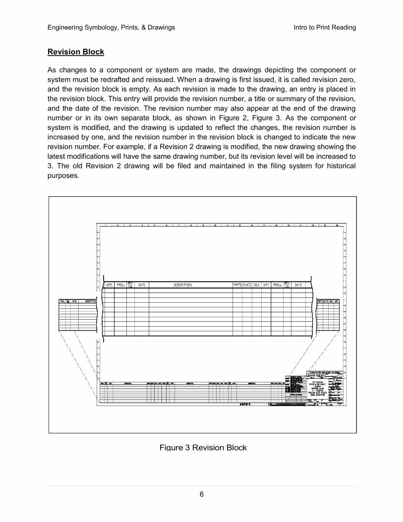
Figure 3 Revision Block
Revision Block
As changes to a component or system are made, the drawings depicting the component or
system must be redrafted and reissued. When a drawing is first issued, it is called revision zero,
and the revision block is empty. As each revision is made to the drawing, an entry is placed in
the revision block. This entry will provide the revision number, a title or summary of the revision,
and the date of the revision. The revision number may also appear at the end of the drawing
number or in its own separate block, as shown in Figure 2, Figure 3. As the component or
system is modified, and the drawing is updated to reflect the changes, the revision number is
increased by one, and the revision number in the revision block is changed to indicate the new
revision number. For example, if a Revision 2 drawing is modified, the new drawing showing the
latest modifications will have the same drawing number, but its revision level will be increased to
3. The old Revision 2 drawing will be filed and maintained in the filing system for historical
purposes.

Engineering Symbology, Prints, & Drawings Intro to Print Reading
7
Changes
There are two common methods of indicating where a revision has changed a drawing that
contains a system diagram. The first is the cloud method, where each change is enclosed by a
hand-drawn cloud shape, as shown in Figure 4. The second method involves placing a circle (or
triangle or other shape) with the revision number next to each effected portion of the drawing, as
shown in Figure 4. The cloud method indicates changes from the most recent revision only,
whereas the second method indicates all revisions to the drawing because all of the previous
revision circles remain on the drawing.
Figure 4 Methods of Denoting Changes
The revision number and revision block are especially useful in researching the evolution of a
specific system or component through the comparison of the various revisions.

Engineering Symbology, Prints, & Drawings Intro to Print Reading
8
Notes and Legend
Drawings are comprised of symbols and lines that represent components or systems. Although
a majority of the symbols and lines are self-explanatory or standard (as described in later
modules), a few unique symbols and conventions must be explained for each drawing. The
notes and legends section of a drawing lists and explains any special symbols and conventions
used on the drawing, as illustrated on Figure 5. Also listed in the notes section is any
information the designer or draftsman felt was necessary to correctly use or understand the
drawing. Because of the importance of understanding all of the symbols and conventions used
on a drawing, the notes and legend section must be reviewed before reading a drawing.
Figure 5 Notes and Legends

Engineering Symbology, Prints, & Drawings Intro to Print Reading
9
Summary
The important information in this chapter is summarized below.
Introduction to Print Reading Summary
The title block of a drawing contains:
o the drawing title
o the drawing number
o location, site, or vendor issuing the drawing
o the design, review, and approval signatures
o the reference block
The grid system of a drawing allows information to be more easily identified using
the coordinates provided by the grid. The coordinate letters and/or numbers break
down the drawing into smaller blocks.
The revision block of a drawing provides the revision number, a title or summary of
the revision, and the date of the revision, for each revision.
The notes and legend section of a drawing provides explanations of special symbols
or conventions used on the drawing and any additional information the designer or
draftsman felt was necessary to understand the drawing.

Engineering Symbology, Prints, & Drawings Intro to Print Reading
10
INTRODUCTION TO THE TYPES OF DRAWINGS, VIEWS, AND PERSPECTIVES
To read a drawing correctly, the user must have a basic understanding of the
various categories of drawings and the views and perspectives in which each
drawing can be presented.
EO 1.5 LIST the five drawing categories used on engineering drawings.
Categories of Drawings
The previous chapter reviewed the non-drawing portions of a print. This chapter will introduce
the five common categories of drawings. They are 1) piping and instrument drawings (P&IDs),
2) electrical single lines and schematics, 3) electronic diagrams and schematics, 4) logic
diagrams and prints, and 5) fabrication, construction, and architectural drawings.
Piping and Instrument Drawings (P&IDs)
P&IDs are usually designed to present functional information about a system or component.
Examples are piping layout, flowpaths, pumps, valves, instruments, signal modifiers, and
controllers, as illustrated in Figure 6.
Figure 6 Example P&ID
Engineering Symbology, Prints, & Drawings Intro to Print Reading
11
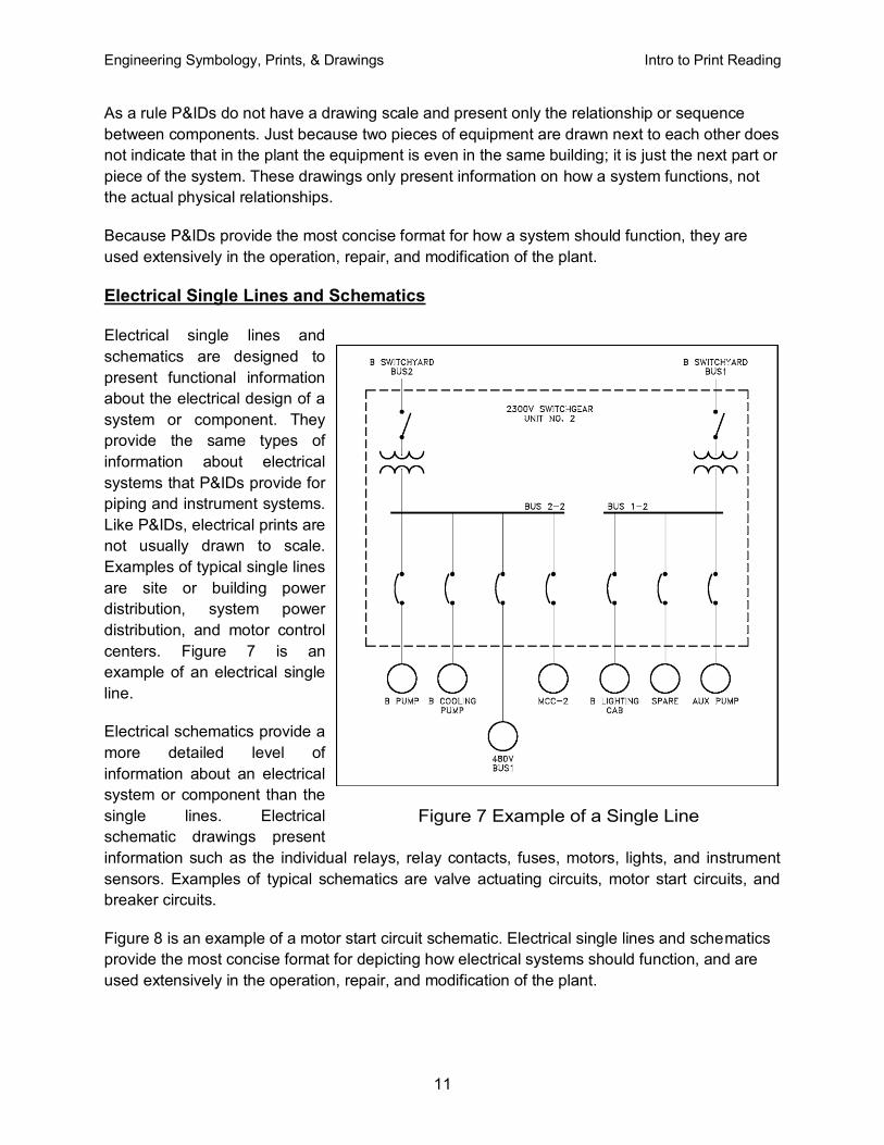
Figure 7 Example of a Single Line
As a rule P&IDs do not have a drawing scale and present only the relationship or sequence
between components. Just because two pieces of equipment are drawn next to each other does
not indicate that in the plant the equipment is even in the same building; it is just the next part or
piece of the system. These drawings only present information on how a system functions, not
the actual physical relationships.
Because P&IDs provide the most concise format for how a system should function, they are
used extensively in the operation, repair, and modification of the plant.
Electrical Single Lines and Schematics
Electrical single lines and
schematics are designed to
present functional information
about the electrical design of a
system or component. They
provide the same types of
information about electrical
systems that P&IDs provide for
piping and instrument systems.
Like P&IDs, electrical prints are
not usually drawn to scale.
Examples of typical single lines
are site or building power
distribution, system power
distribution, and motor control
centers. Figure 7 is an
example of an electrical single
line.
Electrical schematics provide a
more detailed level of
information about an electrical
system or component than the
single lines. Electrical
schematic drawings present
information such as the individual relays, relay contacts, fuses, motors, lights, and instrument
sensors. Examples of typical schematics are valve actuating circuits, motor start circuits, and
breaker circuits.
Figure 8 is an example of a motor start circuit schematic. Electrical single lines and schematics
provide the most concise format for depicting how electrical systems should function, and are
used extensively in the operation, repair, and modification of the plant.

Engineering Symbology, Prints, & Drawings Intro to Print Reading
12
Figure 8 Example of a Schematic

Engineering Symbology, Prints, & Drawings Intro to Print Reading
13
Figure 9 Example of an Electronic Diagram
Electronic Diagrams and Schematics
Electronic diagrams and schematics are designed to present information about the individual
components (resistors, transistors, and capacitors) used in a circuit, as illustrated in Figure 9.
These drawings are usually used by circuit designers and electronics repair personnel.

Engineering Symbology, Prints, & Drawings Intro to Print Reading
14
Logic Diagrams and Prints
Logic diagrams and prints can be used to depict several types of information. The most
common use is to provide a simplified functional representation of an electrical circuit, as
illustrated in Figure 10. For example, it is easier and faster to figure out how a valve functions
and responds to various inputs signals by representing a valve circuit using logic symbols, than
by using the electrical schematic with its complex relays and contacts. These drawings do not
replace schematics, but they are easier to use for certain applications.
Figure 10 Example of a Logic Print
Fabrication, Construction, and Architectural Drawings
Fabrication, construction, and architectural drawings are designed to present the detailed
information required to construct or fabricate a part, system, or structure. These three types of
drawings differ only in their application as opposed to any real differences in the drawings
themselves. Construction drawings, commonly referred to as "blueprint" drawings, present the
detailed information required to assemble a structure on site. Architectural drawings present
information about the conceptual design of the building or structure. Examples are house plans,
building elevations (outside view of each side of a structure), equipment installation drawings,
foundation drawings, and equipment assembly drawings.
Fabrication drawings, as shown in Figure 11, are similar to construction and architectural
drawing but are usually found in machine shops and provide the necessary detailed information
for a craftsman to fabricate a part. All three types of drawings, fabrication, construction, and
architectural, are usually drawn to scale.

Engineering Symbology, Prints, & Drawings Intro to Print Reading
15
Figure 11 Example of a Fabrication Drawing

Engineering Symbology, Prints, & Drawings Intro to Print Reading
16
Drawing Format
P&IDs, fabrication, construction, and architectural drawings can be presented using one of
several different formats. The standard formats are single line, pictorial or double line, and
cutaway. Each format provides specific information about a component or system.
Single Line Drawings
The single line format is most commonly used in P&IDs. Figure 12 is an example of a
single line P&ID. The single line format represents all piping, regardless of size, as
single line. All system equipment is represented by simple standard symbols (covered in
later modules). By simplifying piping and equipment, single lines allow the system's
equipment and instrumentation relationships to be clearly understood by the reader.
Figure 12 Example of a Single Line P&ID
Pictorial or Double Line Drawings
Pictorial or double line drawings present the same type information as a single line, but
the equipment is represented as if it had been photographed. Figure 13 provides an
example illustration of a pictorial drawing. This format is rarely used since it requires
much more effort to produce than a single line drawing and does not present any more
information as to how the system functions. Compare the pictorial illustration, Figure 13,
to the single line of the same system shown in Figure 12. Pictorial or double line
drawings are often used in advertising and training material.

Engineering Symbology, Prints, & Drawings Intro to Print Reading
17
Figure 13 Example Pictorial
Assembly Drawings
Assembly drawing are a special application of pictorial drawings that are common in the
engineering field. As seen in Figure 14, an assembly drawing is a pictorial view of the
object with all the components shown as they go together. This type pictorial is usually
found in vendor manuals and is used for parts identification and general information
relative to the assembly of the component.
Figure 14 Example of an Assembly Drawing

Engineering Symbology, Prints, & Drawings Intro to Print Reading
18
Cutaway Drawings
A cutaway drawing is another special type of pictorial drawing. In a cutaway, as the
name implies, the component or system has a portion cut away to reveal the internal
parts of the component or system. Figure 15 is an illustration of a cutaway. This type of
drawing is extremely helpful in the maintenance and training areas where the way
internal parts are assembled is important.
Figure 15 Example of a Cutaway

Engineering Symbology, Prints, & Drawings Intro to Print Reading
19
Figure 16 Example Orthographic Projection
Views and Perspectives
In addition to the different drawing formats, there are different views or perspectives in which
the formats can be drawn. The most commonly used are the orthographic projection and the
isometric projection.
Orthographic Projections
Orthographic projection is widely used for fabrication and construction type drawings, as
shown in Figure 16. Orthographic projections present the component or system through
the use of three views, These are a top view, a side view, and a front view. Other views,
such as a bottom view, are used to more fully depict the component or system when
necessary.

Engineering Symbology, Prints, & Drawings Intro to Print Reading
20
Figure 17 shows how each of the three views is obtained. The orthographic projection is
typically drawn to scale and shows all components in their proper relationships to each
other. The three views, when provided with dimensions and a drawing scale, contain
information that is necessary to fabricate or construct the component or system.
Figure 17 Orthographic Projections
Isometric Projection
The isometric projection presents a single view of the component or system. The view is
commonly from above and at an angle of 30°. This provides a more realistic three-
dimensional view. As shown on Figure 18, this view makes it easier to see how the
system looks and how its various portions or parts are related to one another. Isometric
projections may or may not be drawn to a scale

Engineering Symbology, Prints, & Drawings Intro to Print Reading
21
Summary
The important information in this chapter is summarized below.
Drawing Types, Views, and Perspectives Summary
The five engineering drawing categories are:
o P&IDs
o Electrical single lines and schematics
o Electronic diagrams and schematics
o Logic diagrams and prints
o Fabrication, construction, and architectural drawings