Engineering Metrology Linear measurements -...
44
Engineering Metrology Linear measurements Dr. Belal Gharaibeh 13/10/2011 1 Dr. B. Gharaibeh Fall 2011
Transcript of Engineering Metrology Linear measurements -...

Engineering Metrology Linear measurements
Dr. Belal Gharaibeh
13/10/2011
1 Dr. B. Gharaibeh Fall 2011

Introduction
• modern manufacturing can produce features that are more accurate than we can measure by hand, therefore we need tools to assist us.
• • These tools allow us to quantitatively evaluate physical properties of objects.
• • EVERY industry uses these tools to some extent, for example,
• - machine shops • - tailors • - dentists • - automotive manufacturers • - etc.
2 Dr. B. Gharaibeh Fall 2011

Definitions • Assembly - the connection of two or more separate parts to
make a new single part.
• Basic Dimension - The target dimension for a part. This typically has an associated tolerance.
• Dimension - A size of a feature, either measured, or specified.
• Dimensional Metrology - The use of instruments to determine object sizes shapes, form, etc.
• Limits - These typically define a dimensional range that a measurement can be expected to fall within.
• Machine Tool - Generally used to refer to a machine that performs a manufacturing operation. This is sometimes confused with the actual cutting tools, such as a drill bit, that do the cutting.
3 Dr. B. Gharaibeh Fall 2011

Definitions • Measurement - The determination of an unknown dimension. This
requires that known standards be used directly, or indirectly for comparison.
• Metric System - A measurement system that has been standardized globally, and is commonly used in all modern engineering projects.
• Metrology - The science of measurement. The purpose of this discipline is to establish means of determining physical quantities, such as dimensions, temperature, force, etc.
• Repeatability - Imperfections in mechanical systems can mean that during a Mechanical cycle, a process does not stop at the same location, or move through the same spot each time. The variation range is referred to as repeatability.
• Standards - a known set of dimensions, or ideals to compare others against.
• Standard Sizes - a component, or a dimension that is chosen from a table of standard sizes/forms.
• Tolerance - The allowable variation in a basic dimension before a part is considered unacceptable
4 Dr. B. Gharaibeh Fall 2011
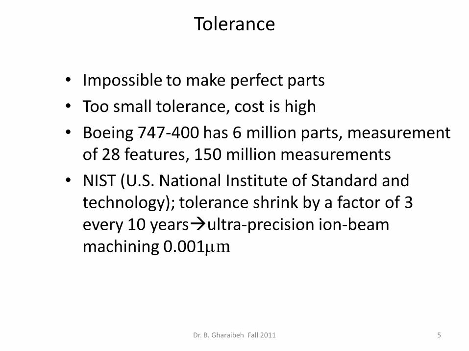
Tolerance
• Impossible to make perfect parts
• Too small tolerance, cost is high
• Boeing 747-400 has 6 million parts, measurement of 28 features, 150 million measurements
• NIST (U.S. National Institute of Standard and technology); tolerance shrink by a factor of 3 every 10 yearsultra-precision ion-beam machining 0.001mm
5 Dr. B. Gharaibeh Fall 2011

6 Dr. B. Gharaibeh Fall 2011

Importance of tolerance
• Parts from the same machine can be different
– Speed of operation
– Temperature
– Lubrication
– Variation of incoming material
– Other factors
• ISO system; definitions
7 Dr. B. Gharaibeh Fall 2011

8 Dr. B. Gharaibeh Fall 2011

Scales • The most common tool for crude measurements
is the scale (also known as rules, or rulers)
• These are limited by the human eye
• Parallax error can be a factor when making measurements with a scale-line of sight not being normal to the scale of the instrument
9 Dr. B. Gharaibeh Fall 2011

Errors
1- Instrument limitations.
2-Geometric errors (flatness and parallelism).
3-Thickness of the grade line.
4-Least increment limitation.
5-Observation error.
6- Alignment error.
7- Parallax error (object not well aligned with scale).
10 Dr. B. Gharaibeh Fall 2011

Calipers • A tool used to transfer measurements from a part to a
scale, or other instrument. • Calipers may be difficult to use, and they require that the
operator follow a few basic rules, – Do not force them, they will bend easily, and invalidate
measurements made – Try to get a feel, or personal technique for using these
instruments. – If measurements are made using calipers for comparison, one
operator should make all of the measurements (this keeps the feel factor a minimal error source).
• These instruments are very useful when dealing with hard to reach locations that normal measuring instruments cannot reach.
• Obviously the added step in the measurement will significantly decrease the accuracy
11 Dr. B. Gharaibeh Fall 2011

Construction & Use:
• They consist of two legs hinged at the top with the ends of the legs span the parts to be inspected.
12 Dr. B. Gharaibeh Fall 2011

Types of calipers.
• Calipers can be classified as : Outside, Inside.
• Calipers can be classified as : Spring, Firm joint, Lock joint , Transfer.
13 Dr. B. Gharaibeh Fall 2011

firm joint calipers
Inside firm joint caliper Outside firm joint caliper 14 Dr. B. Gharaibeh Fall 2011

Spring caliper
Inside spring caliper outside spring caliper
15 Dr. B. Gharaibeh Fall 2011

• Operating principle: They are devices for comparing measurements against known dimensions.
16 Dr. B. Gharaibeh Fall 2011

• Qualities: They should be free from cracks, seams, dirt, flaws and must have smooth bright finish.
• Nominal Size is the distance between the center of the rolling end and the extreme working end of a leg.
17 Dr. B. Gharaibeh Fall 2011

• Caliper’s Capacity is the maximum dimension that can be measured by the caliper. It should not be lesser than the nominal size.
• The accuracy depends on the sense and feel of the operator. Therefore, caliper should be held gently and square to the work with slight gauging pressure applied.
18 Dr. B. Gharaibeh Fall 2011

Instruments • Vernier scales • Like a normal scale with extra secondary scale subdividing
major increments • Secondary scale is one increment shorter than a main scale
therefore indicating relative distance between two offsets of the main scale
• On imperial sliding vernier scales the main scale divisions are 0.050” apart, and on the vernier scale they are 0.049”, giving a reading of 0.001” per graduation.
• On metric sliding vernier scales the main scale divisions are 1mm apart, and the vernier scale they are 0.98 mm, giving a reading of 0.02mm per graduation.
19 Dr. B. Gharaibeh Fall 2011

Scalar vernier
20 Dr. B. Gharaibeh Fall 2011

How to read a vernier caliper.
• The reading on the main scale just before the zero of the vernier is noted. This is called Main scale reading (M.S.R).
• The number of division on the vernier which coincides perfectly with any one of the main scale divisions is noted.T his is called vernier coincidence (V.C).
• The vernier coincidence (V.C) is multiplied by least count to get the fraction of a main scale division. This is added to the main scale reading (M.S.R) to total reading.
21 Dr. B. Gharaibeh Fall 2011

Micrometers
22 Dr. B. Gharaibeh Fall 2011

Micrometer scales
• This is a very common method for measuring instruments, and is based on the thread principle.
• In effect, as a thread is turned, a large motion on the outside of the thread will result in a very small advance in the position of the thread.
• On imperial micrometers the divisions are typically .025” on the sleeve, and 0.001” on the thimble. The thread used has 40 T.P.I. = a pitch of 0.025
• Metric micrometers typically have 1 and 0.5 mm divisions on the sleeve, and 0.01mm divisions on the thimble. The thread has a pitch of 0.5mm.
• Depth micrometers have an anvil that protrudes, out the end, and as a result the scales are reversed to measure extension, instead of retraction.
23 Dr. B. Gharaibeh Fall 2011

• The micrometers pictured below have major scales, as well as minor scales. The major scales are read first, and the micrometer scales are read second and the readings added on.
• The metric micrometer below reads 13.5 = 13.5mm on the major scale, and 31 = .31mm on the thimble, for a total of 13.81mm
• The Imperial scale below shows a micrometer reading of 4.5 = .45” on the main scale, and 9 =.009” on the thimble, for a total of .459
24 Dr. B. Gharaibeh Fall 2011

25 Dr. B. Gharaibeh Fall 2011

26 Dr. B. Gharaibeh Fall 2011

27 Dr. B. Gharaibeh Fall 2011

Magnification The operation of micrometers is based on magnification using threads. • A large movement on the outside of the micrometer thimble will result in a small motion of the spindle • There are two factors in this magnification. First, the difference in radius between the thread, and the thimble will give a change in sensitivity relative to the difference in radii. Second, the pitch of the thread will provide a reduction in motion. M = magnification from the moving head to the hand motion C = measuring diameter of the instrument D = diameter of the thread pitch = the number of threads per unit length
28 Dr. B. Gharaibeh Fall 2011

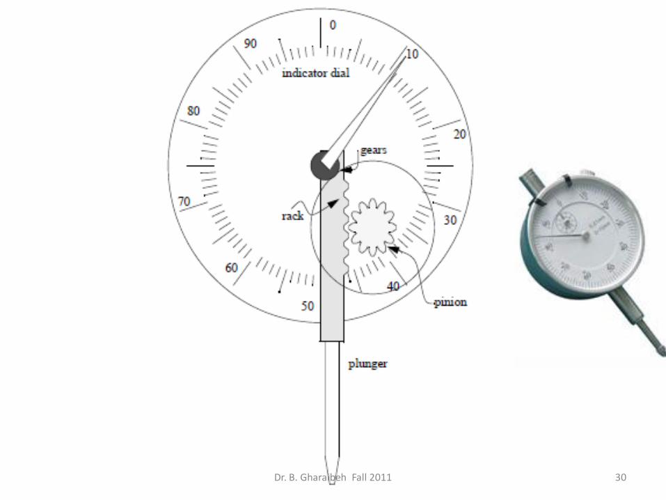
Dial Indicator
• Converts a linear displacement into a radial movement to measure over a small range of movement for the plungers
• The radial arm magnification principle is used here. • These indicators are prone to errors caused by errors that are
magnified through the gear train. • Springs can be used to take up any play/backlash in the rack
and pinion to reduce these errors. • The gears are small, but friction can result in sticking, thus
reducing accuracy • A spring is used on the rack to return the plunger after
depression. • The problems mentioned earlier will result in errors in these
instruments. If the dial indicator is used to approach a dimension from two different sides, it will experience a form of mechanical hysteresis that will bias the readings.
• Causes of hysteresis are: bending strain, inertia, friction and play in the instrument 29 Dr. B. Gharaibeh Fall 2011
30 Dr. B. Gharaibeh Fall 2011

Example of errors in dial indicators
31 Dr. B. Gharaibeh Fall 2011

Gauge blocks
• Blocks with knows linear dimensions within a given tolerances • Requirements of gage blocks
– Known actual size (measured) – Parallel faces – Smooth finish surface – Flat surface
• Gage blocks materials are selected for: – Hardness – Temperature stability – Corrosion resistance – High quality finish
You will have a set of blocks to arrange them by wringing to get the desired dimension
Wringing: sliding blocks on each other with a layer of oil ( 0.2 µ-in)
32 Dr. B. Gharaibeh Fall 2011

Gage blocks continue • there are four grades of blocks,
– reference (AAA) - high tolerance (± 0.00005mm or 0.000002”) – calibration (AA) (tolerance +0.00010mm to -0.00005mm) – inspection (A) (tolerance +0.00015mm to -0.0005mm) – workshop (B) - low tolerance (tolerance +0.00025mm to -
0.00015mm)
• Original gauge block sets had lower tolerances and had a total of 91 pieces with values, 0.010” to 0.100” in 0.001” steps
• An 81 piece set of gauge block was developed by Johansson and is capable of covering wider ranges of dimensions.
• 0.1001” to 0.1009” in 0.0001” steps • 0.1010” to 0.1490” in 0.0010” steps • 0.0500” to 0.9500” in 0.0500” steps • 1.0000”, 2.0000”, 3.0000”, 4.0000” blocks • (2 wear blocks at 0.0500”)
33 Dr. B. Gharaibeh Fall 2011

Example
from the 81 piece set above, build a stack that is 2.5744” -0.1004” 2.4740” -0.1000” 2.3740” -0.1240” 2.2500” -0.2500” 2.0000” -2.0000” 0”
therefore the gauge blocks are, 0.1004” 2 wear blocks @ 0.0500” 0.1240” 0.2500” 2.0000
34 Dr. B. Gharaibeh Fall 2011

Temperature compensation
• Gage block dimensions will change with temperature variation • If the readings are taken at temperature other than the gage blocks
design temperature, then there should be temperature compensation for the dimensional change
• Gage blocks standard temperature is 20 C (68 F) • Temperature will add bias error, either zero offset and/or scale
error • Linear dimensional changes caused by thermal expansion given by:
35 Dr. B. Gharaibeh Fall 2011
mp.ambient te
)(ppm/ materialblock gage theofexpansion of coeff. temp.the
gaged beingpart theofexpansion of coeff. temp. the
re temperatureference standard
together wrungblocks all summing
after length nominal gageblock the
1
r
b
p
r
b
bp
b
T
TT
L
TLL
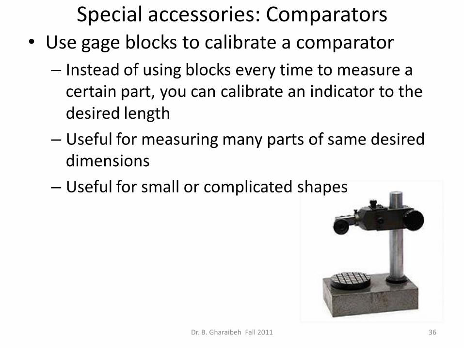
Special accessories: Comparators • Use gage blocks to calibrate a comparator
– Instead of using blocks every time to measure a certain part, you can calibrate an indicator to the desired length
– Useful for measuring many parts of same desired dimensions
– Useful for small or complicated shapes
36 Dr. B. Gharaibeh Fall 2011

Fixed gages • Go/no-go plug type gage • Rule: dimension the plug gage to 10% of the tolerance of the part • The go-no-go gage will be inserted every time in the hole • Go-gage is calibrated using high resolution gage blocks
37 Dr. B. Gharaibeh Fall 2011

Example of fixed gage
• Hole diameter 1.50/1.504 (tolerance =0.004) • Gage tolerance is 0.0004 (10% of original 0.004) • Go side
– 1.500 -0.0001 = 1.4999 – 1.500 +0.0003= 1.5003 – Note: total tolerance is 0.0004 but we make the tolerance
towards the gage wear of the specified limit
• No-go side: • 1.504-0.0002= 1.5038 • 1.5004+0.0002= 1.5042 • Note: tolerance is made equally for the NO-GO limit
because it will not pass through the hole and there is no friction wear
Dr. B. Gharaibeh Fall 2011 38
1.500 1.504

Optical methods-linear measurement
• Areas of measurement:
1. Accurate small dimensions (less than 1 m)
2. Measurement of large dimensions (more than 1 m) by using alignment telescopes with projection systems.
• We will discuss the first type only
39 Dr. B. Gharaibeh Fall 2011

Monochromatic light
• Mono = single • Chromatic = waves, like sound or light • You can produce monochromatic light with a prism. But
this is NOT a good way for measurement • a better way is to use electrical excitation of atoms of
certain elements that radiate light at certain (mono) wavelength (chromatic)
40 Dr. B. Gharaibeh Fall 2011
Prism diffracts light to monochromatic light beams

Lamps and lasers
• Monochromatic lights can be produced by exciting certain material elements in the form of lamps or lasers
• Examples of lasers: – Red: helium-neon (HeNe), blue-green:argon-ion laser
• Gas Lasers are more accurate than lamps because: – Extremely monochromatic with very narrow
monochromatic light
– Collimated light forming narrow and directional beam
– Highly coherent: the light stays in phase with it self for the total length of the beam
41 Dr. B. Gharaibeh Fall 2011

Fringes
The Visible Light Spectrum
Color Wavelength (nm)
Red 625 - 740
Orange 590 - 625
Yellow 565 - 590
Green 520 - 565
Cyan 500 - 520
Blue 435 - 500
Violet 380 - 435
Fringes are half the wavelength distance of a certain lamp or laser, t The distance between fringes indicates the height between the optical flats and work Δd=fringe interval x N = λ/2 x N N: number of fringes
42 Dr. B. Gharaibeh Fall 2011

light for dimensional comparison • Flats and monochromatic light are used as an optical comparator • The number of fringes indicates the height depending on the angle
A
B
C
From light
View direction
Optical flat
work
43 Dr. B. Gharaibeh Fall 2011

Surface plate • Accurate reference plane- very flat surface. • Made of machine-lapped and polished granite surface
plate
• The general advantages of these plates over cast iron are, – durability
• closer tolerances • lower cost • lower thermal expansion
– Quality • non-rusting • burrs do not occur, but chipping does
– ease of use • non-magnetic • less glare • no oil is required, thus dust does not stick • less wringing • inserts are often provided for clamping
44 Dr. B. Gharaibeh Fall 2011