Engineering Method of Prediction of Plume Path of Air ...
6
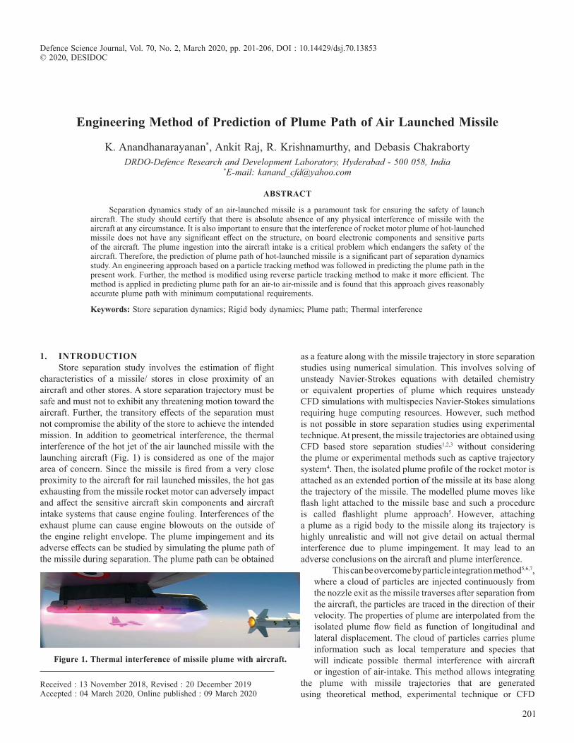
201 Defence Science Journal, Vol. 70, No. 2, March 2020, pp. 201-206, DOI : 10.14429/dsj.70.13853 © 2020, DESIDOC Engineering Method of Prediction of Plume Path of Air Launched Missile K. Anandhanarayanan * , Ankit Raj, R. Krishnamurthy, and Debasis Chakraborty DRDO-Defence Research and Development Laboratory, Hyderabad - 500 058, India * E-mail: [email protected] ABSTRACT Separation dynamics study of an air-launched missile is a paramount task for ensuring the safety of launch aircraft. The study should certify that there is absolute absence of any physical interference of missile with the aircraft at any circumstance. It is also important to ensure that the interference of rocket motor plume of hot-launched missile does not have any significant effect on the structure, on board electronic components and sensitive parts of the aircraft. The plume ingestion into the aircraft intake is a critical problem which endangers the safety of the aircraft. Therefore, the prediction of plume path of hot-launched missile is a significant part of separation dynamics study. An engineering approach based on a particle tracking method was followed in predicting the plume path in the present work. Further, the method is modified using reverse particle tracking method to make it more efficient. The method is applied in predicting plume path for an air-to air-missile and is found that this approach gives reasonably accurate plume path with minimum computational requirements. Keywords: Store separation dynamics; Rigid body dynamics; Plume path; Thermal interference 1. INTRODUCTION Store separation study involves the estimation of flight characteristics of a missile/ stores in close proximity of an aircraft and other stores. A store separation trajectory must be safe and must not to exhibit any threatening motion toward the aircraft. Further, the transitory effects of the separation must not compromise the ability of the store to achieve the intended mission. In addition to geometrical interference, the thermal interference of the hot jet of the air launched missile with the launching aircraft (Fig. 1) is considered as one of the major area of concern. Since the missile is fired from a very close proximity to the aircraft for rail launched missiles, the hot gas exhausting from the missile rocket motor can adversely impact and affect the sensitive aircraft skin components and aircraft intake systems that cause engine fouling. Interferences of the exhaust plume can cause engine blowouts on the outside of the engine relight envelope. The plume impingement and its adverse effects can be studied by simulating the plume path of the missile during separation. The plume path can be obtained as a feature along with the missile trajectory in store separation studies using numerical simulation. This involves solving of unsteady Navier-Strokes equations with detailed chemistry or equivalent properties of plume which requires unsteady CFD simulations with multispecies Navier-Stokes simulations requiring huge computing resources. However, such method is not possible in store separation studies using experimental technique. At present, the missile trajectories are obtained using CFD based store separation studies 1,2,3 without considering the plume or experimental methods such as captive trajectory system 4 . Then, the isolated plume profile of the rocket motor is attached as an extended portion of the missile at its base along the trajectory of the missile. The modelled plume moves like flash light attached to the missile base and such a procedure is called flashlight plume approach 5 . However, attaching a plume as a rigid body to the missile along its trajectory is highly unrealistic and will not give detail on actual thermal interference due to plume impingement. It may lead to an adverse conclusions on the aircraft and plume interference. This can be overcome by particle integration method 5,6,7 , where a cloud of particles are injected continuously from the nozzle exit as the missile traverses after separation from the aircraft, the particles are traced in the direction of their velocity. The properties of plume are interpolated from the isolated plume flow field as function of longitudinal and lateral displacement. The cloud of particles carries plume information such as local temperature and species that will indicate possible thermal interference with aircraft or ingestion of air-intake. This method allows integrating the plume with missile trajectories that are generated using theoretical method, experimental technique or CFD Figure 1. Thermal interference of missile plume with aircraft. Received : 13 November 2018, Revised : 20 December 2019 Accepted : 04 March 2020, Online published : 09 March 2020
Transcript of Engineering Method of Prediction of Plume Path of Air ...
201
Defence Science Journal, Vol. 70, No. 2, March 2020, pp. 201-206, DOI : 10.14429/dsj.70.13853 © 2020, DESIDOC
Engineering Method of Prediction of Plume Path of Air Launched Missile
K. Anandhanarayanan*, Ankit Raj, R. Krishnamurthy, and Debasis Chakraborty DRDO-Defence Research and Development Laboratory, Hyderabad - 500 058, India
*E-mail: [email protected]
AbstrAct
Separation dynamics study of an air-launched missile is a paramount task for ensuring the safety of launch aircraft. The study should certify that there is absolute absence of any physical interference of missile with the aircraft at any circumstance. It is also important to ensure that the interference of rocket motor plume of hot-launched missile does not have any significant effect on the structure, on board electronic components and sensitive parts of the aircraft. The plume ingestion into the aircraft intake is a critical problem which endangers the safety of the aircraft. Therefore, the prediction of plume path of hot-launched missile is a significant part of separation dynamics study. An engineering approach based on a particle tracking method was followed in predicting the plume path in the present work. Further, the method is modified using reverse particle tracking method to make it more efficient. The method is applied in predicting plume path for an air-to air-missile and is found that this approach gives reasonably accurate plume path with minimum computational requirements.
Keywords: Store separation dynamics; Rigid body dynamics; Plume path; Thermal interference
1. IntroductIonStore separation study involves the estimation of flight
characteristics of a missile/ stores in close proximity of an aircraft and other stores. A store separation trajectory must be safe and must not to exhibit any threatening motion toward the aircraft. Further, the transitory effects of the separation must not compromise the ability of the store to achieve the intended mission. In addition to geometrical interference, the thermal interference of the hot jet of the air launched missile with the launching aircraft (Fig. 1) is considered as one of the major area of concern. Since the missile is fired from a very close proximity to the aircraft for rail launched missiles, the hot gas exhausting from the missile rocket motor can adversely impact and affect the sensitive aircraft skin components and aircraft intake systems that cause engine fouling. Interferences of the exhaust plume can cause engine blowouts on the outside of the engine relight envelope. The plume impingement and its adverse effects can be studied by simulating the plume path of the missile during separation. The plume path can be obtained
as a feature along with the missile trajectory in store separation studies using numerical simulation. This involves solving of unsteady Navier-Strokes equations with detailed chemistry or equivalent properties of plume which requires unsteady CFD simulations with multispecies Navier-Stokes simulations requiring huge computing resources. However, such method is not possible in store separation studies using experimental technique. At present, the missile trajectories are obtained using CFD based store separation studies1,2,3 without considering the plume or experimental methods such as captive trajectory system4. Then, the isolated plume profile of the rocket motor is attached as an extended portion of the missile at its base along the trajectory of the missile. The modelled plume moves like flash light attached to the missile base and such a procedure is called flashlight plume approach5. However, attaching a plume as a rigid body to the missile along its trajectory is highly unrealistic and will not give detail on actual thermal interference due to plume impingement. It may lead to an adverse conclusions on the aircraft and plume interference.
This can be overcome by particle integration method5,6,7, where a cloud of particles are injected continuously from the nozzle exit as the missile traverses after separation from the aircraft, the particles are traced in the direction of their velocity. The properties of plume are interpolated from the isolated plume flow field as function of longitudinal and lateral displacement. The cloud of particles carries plume information such as local temperature and species that will indicate possible thermal interference with aircraft or ingestion of air-intake. This method allows integrating
the plume with missile trajectories that are generated using theoretical method, experimental technique or CFD
Figure 1. thermal interference of missile plume with aircraft.
Received : 13 November 2018, Revised : 20 December 2019 Accepted : 04 March 2020, Online published : 09 March 2020

DEF. SCI. J., VOl. 70, NO. 2, MARCH 2020
202
simulations using Euler/ Navier-Stokes solver. The details of integration method for plume path modelling are presented in the following sections. Further, a modification to the method is proposed in the present work using reverse particle tracing to make the method faster and efficient. The above method is integrated with the grid-free Euler solver based store separation dynamics suite8 and applied to obtain the plume path for an air-to-air missile that is launched from an aircraft.
2. MEthodoLogy
The prediction of plume path involves generation of missile trajectory using store separation study, generation of isolated plume profile and finally integration of plume with the trajectory of missile.
2.1 trajectory generationThe missile trajectory can be obtained using theoretical,
CFD or experimental methods. In the present work, the missile trajectory was obtained using an integrated store separation dynamics suite8. The suite includes a preprocessor, a grid free Euler solver based on Entropy variables (q) least Squares Kinetic Upwind Method (q-lSKUM) and a six Degrees Of Freedom (6-DOF) solver. The grid-free solver operates on a cloud of points that is distributed around the geometry. The distribution of points is obtained by generating unstructured grids around the aircraft and store independently and overlapping them at appropriate position to form overlapped or chimera cloud of points8. The preprocessor overlaps the unstructured grid around the aircraft and missile to form chimera cloud of points, removes the points that lie inside the solid components of aircraft and missile due to overlapping of grids. Then, the preprocessor identifies a set of neighbouring points (local cloud), known as connectivity, around each point in the distribution of points. The cloud around the missile is moved relative to the cloud around aircraft and connectivity is updated at every time step. q-lSKUM Euler code is applied on the chimera clouds and the aerodynamic forces and moments on the missile and aircraft are obtained. These forces and moments are solved along with the inertial forces and constraint forces using the 6-DOF solver to obtain a new position of the missile which goes as input to the preprocessor. The above procedure is applied till the missile reaches safe separation distance or any component of the missile colliding with any part of the aircraft. These codes are coupled to form store separation dynamics (SSD) suite. The store separation study provides the trajectory of missile that is launched from an aircraft. The trajectory of missile includes displacement, velocity, body rates and Euler angles of the missile at different instants of time. Typical trajectory of missile is shown in Fig. 2. The SSD suite based on the above methodology has been applied to simulate separation dynamics an air-to-air missile9. The computed displacement, body rates and attitude compare well with the flight recorded data.
2.2 Axis system of MissileThe motion of the missile is modelled using equations
of motion and these equations represent the motion of a rigid body relative to an inertial coordinate system XYZ. The
inertial axis system is attached to the aircraft and is originated from O, the centre of gravity of missile at the instant of store separation begins, as shown in Fig. 3. A body-fixed coordinate system XbYbZb whose origin is at the centre of gravity of missile and is attached to the missile during separation. The orientation of the body axis relative to the inertial axis can be described in terms of three consecutive rotations through body referenced Euler angles, ψ, θ, φ, respectively the azimuth angle, the pitch angle and the bank angle. The aerodynamic forces and moments of the aircraft and missile are obtained in the inertial system using CFD code, whereas the equations of motion are solved by integrating the aerodynamic force along with inertial force in the body axis system using the 6-DOF solver. The transformation of forces from the inertial axis to the body axis using the above Euler angles. The solutions of equations of motion include components of missile displacement (x,y,z), missile velocity (u,v,w), missile body rates (p,q,r) and Euler angles (φ,ψ,θ). The body velocity and displacement are transformed back to the inertial axis to place the store with respect to the aircraft and imposition of missile velocity boundary condition relative to the aircraft in the CFD simulations.
2.3 Plume Profile generationSimilar to the missile trajectory, an isolated plume profile
is also generated independently. The plume profile consists of distribution of temperature, pressure and velocity of the gas as function of spatial co-ordinates. The plume profiles can also be obtained using theoretical or CFD methods. The isolated plume profiles, used in the present work, were generated by solving three dimensional Reynolds Averaged Navier Stokes (RANS) equations solver along with chemical species and turbulence transport equations using a commercial CFD solver10. The isolated plume profiles at altitudes 4.5 km and 15 km are shown in Fig. 4. The solutions of RANS solver include local temperature, pressure, density, concentration of species, components of velocity and turbulent quantities within the complete flow domain and other parameters such as Mach number, total pressure are derived from the above parameters.
Figure 2. Missile trajectory using ssd suite.
Figure 3. co-ordinate system.

ANANDHANARAyANAN, et al.: ENgINEERINg METHOD OF PREDICTION OF PlUME PATH OF AIR lAUNCHED MISSIlE
203
Using both missile trajectory and plume profile, the plume path is generated. Two approaches are followed to generate plume path viz., flashlight and flexible methods. In the flashlight approach, the entire plume is assumed as rigid body and attached to the missile base with the instantaneous orientation of missile. This is done by rotating the isolated plume profile with the instant Euler angle of missile (with respect to the inertial frame) followed by translating the plume to the missile base. Figure 5 shows a representative flashlight plume attached to missile base at different instant of time. By integrating plume with the missile trajectory, all the flow parameters of plume is available in space at different instant of time and these parameters can be used to identify the issues related to plume ingestion, local kinetic heating and structural integrity.
2.4 Plume Path Prediction using the Integration MethodIn the flexible approach, a cloud of particles are
continuously injected at the nozzle exit at different instant of time with a relative velocity, obtained from the isolated plume profile, with respect to missile in the opposite direction of instantaneous orientation of the missile. These particles are integrated over a time period to get a cloud of plume particles. This approach is analogous to Kinetic Particle Method11 in which Euler equations are solved in two steps, viz., modelling
of convection step by transporting particle with its velocity and modelling of collision by projecting on to the local equilibrium.
A procedure similar to the above is followed in the integration method, where, the particles are continuously injected at the nozzle exit with the local properties of plume and these particles are traced in the space with finite time steps. Actually, injection of plume particles and its movement between the initial time to instant of observation is a continuous process. However, in the discrete simulation, the continuous process of particle
injection and particle movement is decoupled by a small time-step Δt, i.e. once a cloud of particles is injected at t0, they are traced for a duration of Δt, before next set of cloud of particles is injected at t=t0+Δt. Further during each time step Δt, each particle is moved in small discrete sub-time steps. The small sub-time is selected such that the particle does not cross more than a cell in a sub-time step. The particles continue to travel in the opposite direction of the missile with the relative velocity of plume with respect to the missile at the time of injection. Each particle preserves the orientation of missile (or plume) with respect to the inertial frame at the time of its birth and the time of its injection. As the particle traverses, its present position in space is mapped to the isolated plume profile based on its orientation and time of injection. Then, its properties are interpolated from the isolated plume profile and are marched further. Since such particle life is limited to few seconds, these particles are removed as the particle crosses the domain of isolated plume. As so many particles are injected continuously, these particles represent the trails of the plume as the missile traverses along its trajectory. This represents the flexible plume path as shown in Fig. 6.
generally, the plume particles in the core have two order higher velocity compared to the particles at the edge of the plume. Therefore, many particles injected at the core would have left the domain of interest by the time the particles along
the edge of plume cover a considerable distance. This require a large number of particles need to be injected with smaller time intervals which require considerable computing time and memory, even though the plume path generation requirement is a small fraction of time required to carry out the integrated store separation studies for the complete trajectory of the missile. It was noted that the particle position and its properties depend on the missile orientation at the time of the particle injection. Considering this, the method is modified in the present work to generate plume path efficiently.
3. ModIFIEd IntEgrAtIon MEthod to obtAIn FLExIbLE PLuME
As in the original method, the isolated plume flow field is generated using Navier-stokes solver. As a first step, in the modified method, the plume boundary is identified using temperature criteria. In the present work, an isotherm surface whose temperature 5 per cent more than the free-stream temperature is considered as plume boundary. Structured grids are used in simulating the isolated plume. The outer boundary of the plume is
Figure 4. Mach number distribution of plume profile (a) Altitude 4.5 km, (b) Altitude 15 km.
Figure 5. Plume path at time instants using flashlight plume approach.
Figure 6. Plume path obtained using flexible plume approach.
(a)
(b)

DEF. SCI. J., VOl. 70, NO. 2, MARCH 2020
204
identified by starting from the grid points on the axi-symmetry line and marching outward till the static temperature is more than the free-stream temperature by 5 per cent. This boundary is defined as outer boundary of plume profile. Typical plume field and identified plume boundary are shown in Fig. 7(a). This forms a closed axi-symmetric contour encompassing the plume. Two boundaries, plume centre-line and plume boundary, are identified and an axi-symmetric algebraic grid is generated within the two boundaries, as shown in Fig. 7(b). The plume properties from the isolated plume profiles are bi-linearly interpolated to these grid points. In the present method, these grid points are assumed as cloud of particles that were exhausted from the missile at different time instants and the grid location is referred here as reference position of the particle. The particles are back tracked in the background grid till the plane of the base of the missile with local velocity that are interpolated from the isolated plume properties. The time taken for the particle to travel the distance from the missile base to the respective grid point is computed. The time to travel in seconds for each particle at respective grid point as function of spatial locations is shown in Fig. 7(c).
The plume path at any given instant of time along the missile trajectory can be easily constructed using the time to travel and corresponding missile orientation and position. A plume particle at any instant of observing time (to) must have emanated from the missile base at (to - tp), where, tp is the time travel of the particle from the base to its reference position that was obtained from the reverse tracking method. At the time of ejection, the direction of velocity of particle and position can be related to the relative velocity and orientation of the missile with respect to the aircraft. Therefore, the plume particle corresponding to each grid point can be positioned in the space with respect to the aircraft using the above information and their properties which were known from the corresponding reference solution. Thus constructed plume particles will represent the plume path that can be observed relative to the aircraft.
The thermal interference at any point on the aircraft during missile separation can be easily computed by interpolating time to travel from the grid and corresponding plume properties. Plume path along the trajectory of the missile is predicted using modified particle integration model. The predicted plume path using modified method is shown in Fig. 7(d). It was observed that the new method needs few hundreds of plume
particle compared to the earlier method which requires few ten thousands of particles to obtain reasonably accurate plume path. Therefore, the present method requires a very small fraction of simulation time compared to the earlier method to obtain the plume path.
The trajectory parameters of an air-to-air missile launched from a fighter aircraft with time are shown in Fig. 8. The plume trajectories for the missile are generated using reverse particle tracking method at different instants of time and are shown in Fig. 9. The temperature contours are shown along the plume path. It can be clearly seen that the flexible plume comes very close to the aircraft air-intake, but there is no plume ingestion by the air-intake. The computed plume position, Mach number and static temperature are used to determine the increase in surface temperature for verification of the structural integrity of aircraft skin, missile launcher and flight instruments.
4. concLusIonsPrediction of plume path is a very important task for
the flight clearance of rail launched missiles. Flexible plume approach using plume particle integration method gives accurate plume profile for analysis of thermal interference of missile plume with the launching aircraft. In the present work,
Figure 7. prediction of plume path of missile using reverse particle tracing method :(a) Plume boundary, (b) axi-symmetric grid within plume, (c) Particle travel time to reach respective points, and (d) top view of plume path.
Figure 8. trajectory parameters of missile launched from the aircraft: (a) displacement, (b) body rates, and (c) Euler angles.(a) (b) (c)
(c)
(d)
(b)
(a)

ANANDHANARAyANAN, et al.: ENgINEERINg METHOD OF PREDICTION OF PlUME PATH OF AIR lAUNCHED MISSIlE
205
a reverse particle tracking method is proposed to obtain the plume path. Then, the method is applied to generate the plume path of the missile at different instant of time during separation from the aircraft to show its efficacy. It was observed that the present method is as accurate as the earlier method7, but with considerably less number of plume particles (order of ten thousand) in comparison with the earlier method which require few millions of particles and therefore, reduced simulation time to obtain the plume path.
rEFErEncEs1. Murman, S.M.; Aftosmis, M.J. & Berger, M.J. Simulations
of store separation from an F/A-18 with a Cartesian method. Journal Aircraft, 2004, 41(4), 870-878.
doi:10.2514/1.4732. lijewski, l. E. & Suhs, N. E. Time-accurate computational
fluid dynamics approach to transonic store separation trajectory prediction. Journal Aircraft, 1994, 31(4), 886-891.
doi:10.2514/3.465753. Stokes, S. & Chappell, J.A. & Leatham, M. Efficient
numerical store trajectory prediction for complex aircraft/store configurations. AIAA paper No. 99-3712, June, 1999. 30th AIAA Fluid Dynamics Conference, 28 June - 1 July, 1999 , Norfolk, VA.
doi:10.2514/6.1999-37124. Bamber, M. J. Store separation investigations by grid
method using wind tunnel data. David Taylor Model Basin, Report 2202, April 1966.
5. Rupert, gleissl & Ronald, M. Deslandes. Simulation of missile plumes for aircraft store compatibility assessments. AIAA Paper No. AIAA 2005-54, 2005.
doi:10.2514/6.2005-54 6. Rupert, gleissl; Ronald, M. Deslandes & André, Baeten,
Assessment of missile plume impact characteristics. AIAA Paper No. AIAA 2007-675, 2007.
doi:10.2514/6.2007-6757. Raj, Ankit & Anandhanarayanan, K. Modeling of missile
plume path during store separation. In Proceedings of Symposium on Applied Aerodynamics and design of Aerospace Vehicle (SAROD 2011), November 16-18, 2011, Bangalore, India.
8. Anandhanarayanan, K. Development of three-dimensional grid-free solver and its applications to multi-body aerospace vehicles. Def. Sci. J., 2010, 60(6), 653-662.
doi:10.14429/dsj.60.5839. Anandhanarayanan, K.; Raj, Ankit; Shah, Vaibhav;
Krishnamurthy, R. & Chakraborty, Debasis. Separation dynamics of air-to-air missile and validation with flight data. Def. Sci. J., 2018, 68(1), 5-11.
doi:10.14429/dsj.68.1148010. Dharavath, Malsur; Manna, P. & Chakraborty, Debasis.
Numerical exploration of low altitude rocket plume in aircraft vicinity. J. Aerospace Sci. Technol., 68(4), 221-
Figure 9. Integrated plume at different time instants (M = 0.6, α = 5°, h = 8km).

DEF. SCI. J., VOl. 70, NO. 2, MARCH 2020
206
232.11. Tiwari, S. Coupling of the Boltzmann and Euler equations
with automatic domain decomposition. J. Comput. Phy., 1998, 144, 710–726.
doi:10.1006/jcph.1998.6011
AcKnowLEdgEMEntsAuthors express their sincere gratitude to the Director
DRDl and the Project Director, for their support and encouragement throughout the work. Authors wish to thank Mr Malsur Dharavath, Scientist, CCD Division, for providing the plume data to test the plume path integration method.
contrIbutors
dr K. Anandhanarayanan, received his BTech (Aeronautical Engineering) from MIT, Chennai, in 1991, ME (guided Missiles) from IAT, Pune, in 1993 and PhD from Dept. of Aerospace Engineering, Indian Institute of Science, Bangalore, in 2004. He is working in the DRDO-Defence Research and Development laboratory, Hyderabad. His areas of interests are Algorithm development for CFD applications, grid-free Euler and Navier-Stokes solvers, Direct Simulation Monte Carlo based Euler-Boltzmann coupled solver for non-equilibrium transitional flows and Distributed Computing. He is a member of various bodies like the AeSI, IEI, and ASI. His contributions to the present work are development of algorithm and implementation.
Mr Ankit raj received his BTech (Mechanical Engineering) from NIT Jalandhar, in 2009. He is working in the DRDO-Defence Research and Development laboratory, Hyderabad.
His areas of interests are grid generation, store separation dynamics and optimisation. His contributions to the present work are application store separation suite and the plume integration code to obtain plume path.
dr r. Krishnamurthy received his BTech (Aeronautical Engineering) from MIT, Chennai, in 1988, ME from IISc., Bangalore, in 1990 and PhD from Department of Aerospace Engineering, IISc, Bangalore, in 2002. He is working in the DRDO-Defence Research and Development laboratory, Hyderabad since 1990. He is presently heading the Computational Fluid Dynamics Division and working on aerodynamic characterisation of missiles. He has published more than 60 technical papers in journals/conference proceedings. He is a recipient of Dr. Biren Roy Trust Award – 1991, DRDO Technology Award – 1994, DRDL Technology Award – 2008, DRDO Special Award for Strategic Contribution – 2014 and DRDO Award for Path Breaking Research / Outstanding Technology Development - 2015 as team awards. His contribution in the present work is to provide overall guidance to the team and coordination with project for obtaining various inputs.
dr debasis chakraborty obtained his PhD in Aerospace Engineering from Indian Institute of Science, Bengaluru. Presently, he is working as Technology Director, Computational Dynamics, DODO-Defence Research and Development laboratory, Hyderabad. His research interests are CFD, aero-dynamics, high-speed combustion, and propulsion. He has about 48 journal and 58 conference publications to his credit.His contribution in the present work is to provide overall guidance to the team.