Engineering Mechanics: Statics - · PDF file1 Engineering Mechanics: Statics Chapter 2: Force...
16
1 Engineering Mechanics: Statics Chapter 2: Force Systems Part A: Two Dimensional Force Systems Force Force = an action of one body on another Vector quantity External and Internal forces Mechanics of Rigid bodies: Principle of Transmissibility • Specify magnitude, direction, line of action • No need to specify point of application Concurrent forces • Lines of action intersect at a point
Transcript of Engineering Mechanics: Statics - · PDF file1 Engineering Mechanics: Statics Chapter 2: Force...
1
Engineering Mechanics: Statics
Chapter 2: Force SystemsPart A: Two Dimensional Force Systems
Force
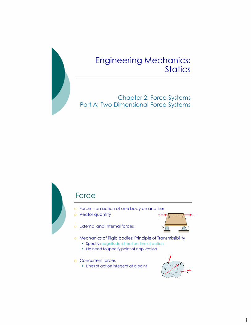
� Force = an action of one body on another
� Vector quantity
� External and Internal forces
� Mechanics of Rigid bodies: Principle of Transmissibility
• Specify magnitude, direction, line of action
• No need to specify point of application
� Concurrent forces
• Lines of action intersect at a point
2
2D Force Systems
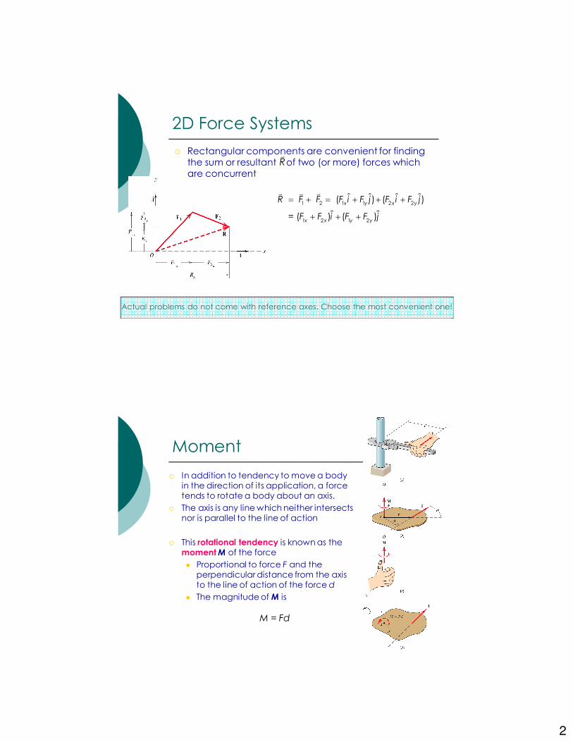
� Rectangular components are convenient for finding the sum or resultant of two (or more) forces which are concurrent
Rv
1 2 1 1 2 2
1 2 1 2
ˆ ˆ ˆ ˆ ( ) ( )
ˆ ˆ = ( ) ( )
x y x y
x x y y
R F F F i F j F i F j
F F i F F j
= + = + + +
+ + +
v v v
Actual problems do not come with reference axes. Choose the most convenient one!
Moment
� In addition to tendency to move a body in the direction of its application, a force tends to rotate a body about an axis.
� The axis is any line which neither intersects nor is parallel to the line of action
� This rotational tendency is known as the momentM of the force
� Proportional to force F and the perpendicular distance from the axis to the line of action of the force d
� The magnitude of M is
M = Fd
3
Moment
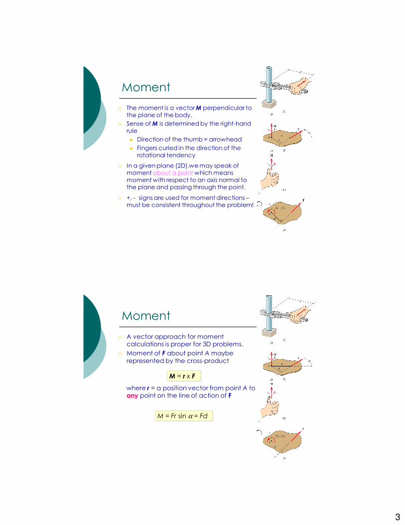
� The moment is a vector M perpendicular to the plane of the body.
� Sense of M is determined by the right-hand rule
� Direction of the thumb = arrowhead
� Fingers curled in the direction of the rotational tendency
� In a given plane (2D),we may speak of moment about a point which means moment with respect to an axis normal to the plane and passing through the point.
� +, - signs are used for moment directions –must be consistent throughout the problem!
Moment
� A vector approach for moment calculations is proper for 3D problems.
� Moment of F about point A maybe
represented by the cross-product
where r = a position vector from point A to any point on the line of action of F
M = r x F
M = Fr sin α = Fd

4
Example 2/5 (p. 40)
Calculate the magnitude of the moment about the base point O of the 600-N force by using both scalar and vector approaches.
Problem 2/50
(a) Calculate the moment of the 90-N force about point O for the condition θ = 15º.
(b) Determine the value of θ for which the
moment about O is (b.1) zero (b.2) a maximum
5
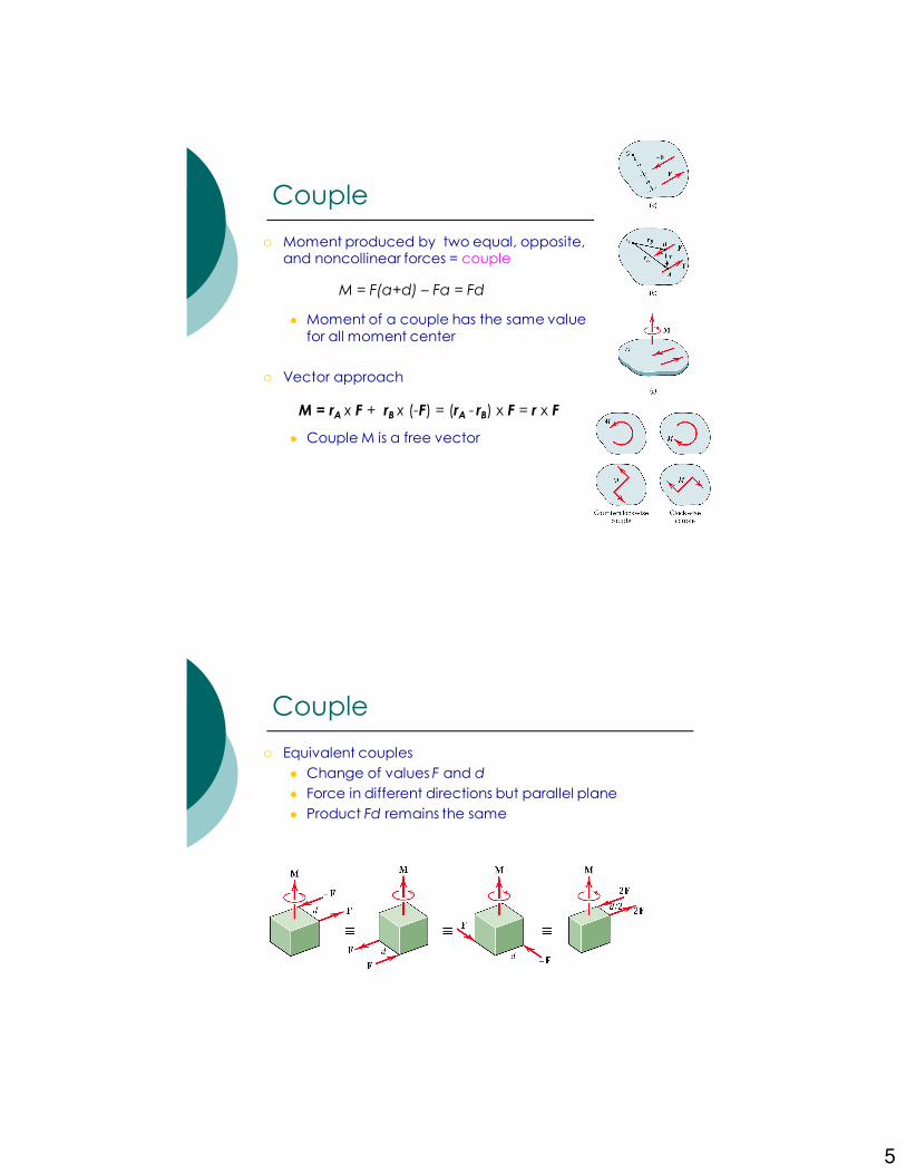
Couple
� Moment produced by two equal, opposite, and noncollinear forces = couple
� Moment of a couple has the same value
for all moment center
� Vector approach
� Couple M is a free vector
M = F(a+d) – Fa = Fd
M = rA x F + rB x (-F) = (rA - rB) x F = r x F
Couple
� Equivalent couples
� Change of values F and d
� Force in different directions but parallel plane
� Product Fd remains the same
6
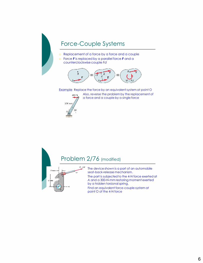
Force-Couple Systems
� Replacement of a force by a force and a couple
� Force F is replaced by a parallel force F and a counterclockwise couple Fd
Example Replace the force by an equivalent system at point O
Also, reverse the problem by the replacement of a force and a couple by a single force
Problem 2/76 (modified)
The device shown is a part of an automobile seat-back-release mechanism.
The part is subjected to the 4-N force exerted at A and a 300-N-mm restoring moment exerted by a hidden torsional spring.
Find an equivalent force-couple system at point O of the 4-N force
7
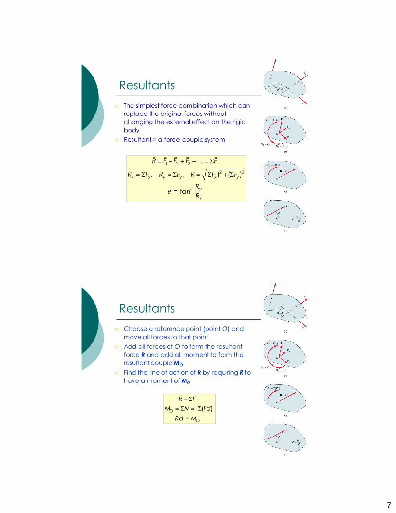
Resultants
� The simplest force combination which can
replace the original forces without
changing the external effect on the rigid
body
� Resultant = a force-couple system
1 2 3
2 2
-1
, , ( ) ( )
= tan
x x y y x y
y
x
R F F F F
R F R F R F F
R
Rθ
= + + + = Σ
= Σ = Σ = Σ + Σ
v v v v v
K
Resultants
� Choose a reference point (point O) and
move all forces to that point
� Add all forces at O to form the resultant
force R and add all moment to form the
resultant coupleMO
� Find the line of action of R by requiring R to
have a moment of MO
( )
=
O
O
R F
M M Fd
Rd M
= Σ
= Σ = Σ
v v
8
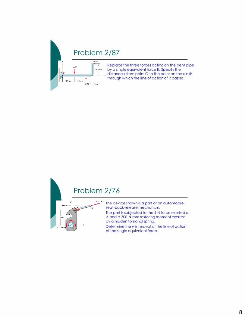
Problem 2/87
Replace the three forces acting on the bent pipe by a single equivalent force R. Specify the distance x from point O to the point on the x-axis through which the line of action of R passes.
Problem 2/76
The device shown is a part of an automobile seat-back-release mechanism.
The part is subjected to the 4-N force exerted at A and a 300-N-mm restoring moment exerted by a hidden torsional spring.
Determine the y-intercept of the line of action of the single equivalent force.

9
Force Systems
Part B: Three Dimensional Force Systems
� Rectangular components in 3D
•Express in terms of unit vectors , ,
•cosθx, cosθy , cosθz are the direction cosines
•cosθx = l, cosθy = m, cosθ z= n
Three-Dimensional Force System
ˆ ˆ ˆ x y zF F i F j F k= + +v
2 2 2
x y zF F F F= + +
i j k
cos , cos , cosx x y y z zF F F F F Fθ θ θ= = =
ˆ ˆ ˆ ( )F F li mj nk= + +v
10
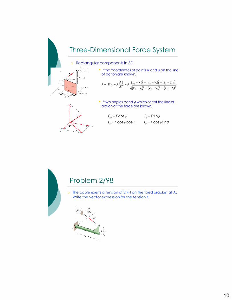
� Rectangular components in 3D
• If the coordinates of points A and B on the line of action are known,
• If two angles θ and φ which orient the line of action of the force are known,
Three-Dimensional Force System
2 1 2 1 2 1
2 2 2
2 1 2 1 2 1
ˆ ˆ ˆ( ) ( ) ( )
( ) ( ) ( )F
x x i y y j z z kABF Fn F F
AB x x y y z z
− + − + −= = =
− + − + −
vv v
cos , sin
cos cos , cos sin
xy z
x y
F F F F
F F F F
φ φ
φ θ φ θ
= =
= =
Problem 2/98
� The cable exerts a tension of 2 kN on the fixed bracket at A.
Write the vector expression for the tension T.
11
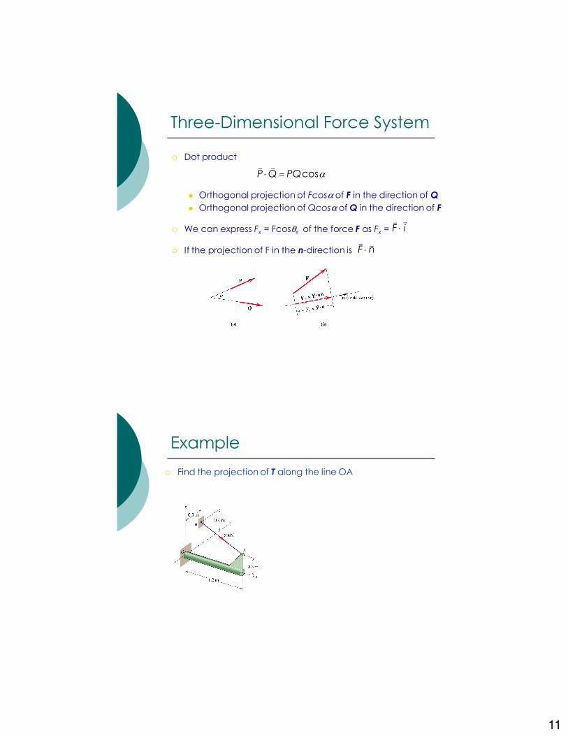
� Dot product
� Orthogonal projection of Fcosα of F in the direction of Q
� Orthogonal projection of Qcosα of Q in the direction of F
� We can express Fx = Fcosθx of the force F as Fx =
� If the projection of F in the n-direction is
Three-Dimensional Force System
cosP Q PQ α⋅ =vv
F i⋅vv
F n⋅v v
Example
� Find the projection of T along the line OA
12
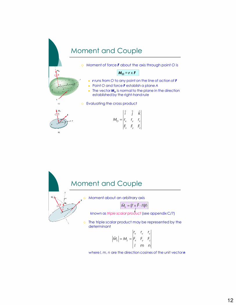
� Moment of force F about the axis through point O is
� r runs from O to any point on the line of action of F
� Point O and force F establish a plane A
� The vector Mo is normal to the plane in the direction established by the right-hand rule
� Evaluating the cross product
Moment and Couple
MO = r x F
ˆ ˆ ˆ
O x y z
x y z
i j k
M r r r
F F F
=
� Moment about an arbitrary axis
known as triple scalar product (see appendix C/7)
� The triple scalar product may be represented by the determinant
where l, m, n are the direction cosines of the unit vectorn
Moment and Couple
( )M r F n nλ = × ⋅v vv v v
x y z
x y z
r r r
M M F F F
l m n
λ λ= =
v
13
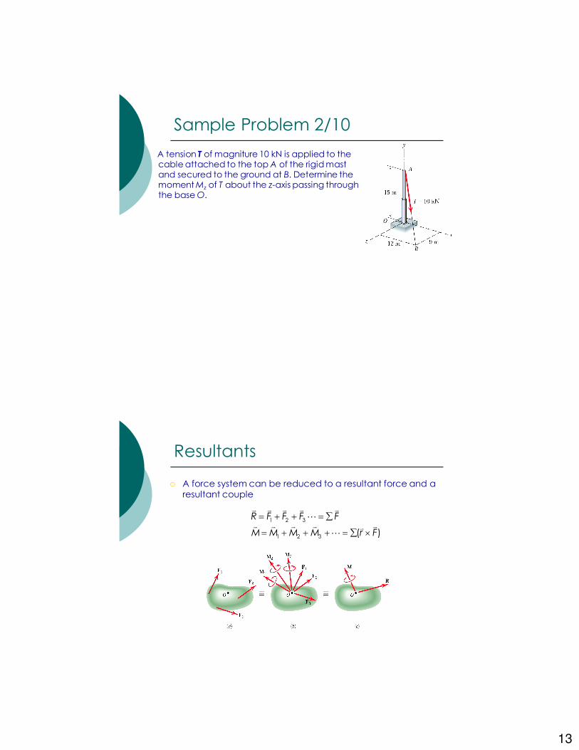
A tension T of magniture 10 kN is applied to the cable attached to the top A of the rigid mast and secured to the ground at B. Determine the moment Mz of T about the z-axis passing through the base O.
Sample Problem 2/10
� A force system can be reduced to a resultant force and a resultant couple
Resultants
1 2 3
1 2 3 ( )
R F F F F
M M M M r F
= + + = ∑
= + + + = ∑ ×
v v v v v
L
v v v v vvL
14
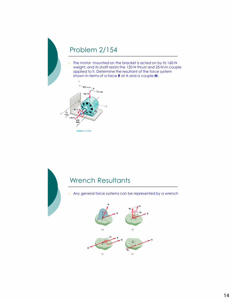
� The motor mounted on the bracket is acted on by its 160-N weight, and its shaft resists the 120-N thrust and 25-N.m couple applied to it. Determine the resultant of the force system shown in terms of a force R at A and a couple M.
Problem 2/154
� Any general force systems can be represented by a wrench
Wrench Resultants

15
� Replace the two forces and single couple by an equivalent force-couple system at point A
� Determine the wrench resultant and the coordinate in the xy plane through which the resultant force of the wrench acts
Problem 2/143
� Special cases
• Concurrent forces – no moments about point of concurrency
• Coplanar forces – 2D
• Parallel forces (not in the same plane) – magnitude of resultant = algebraic sum of the forces
• Wrench resultant – resultant couple M is parallel to the resultant force R
• Example of positive wrench = screw driver
Resultants
16
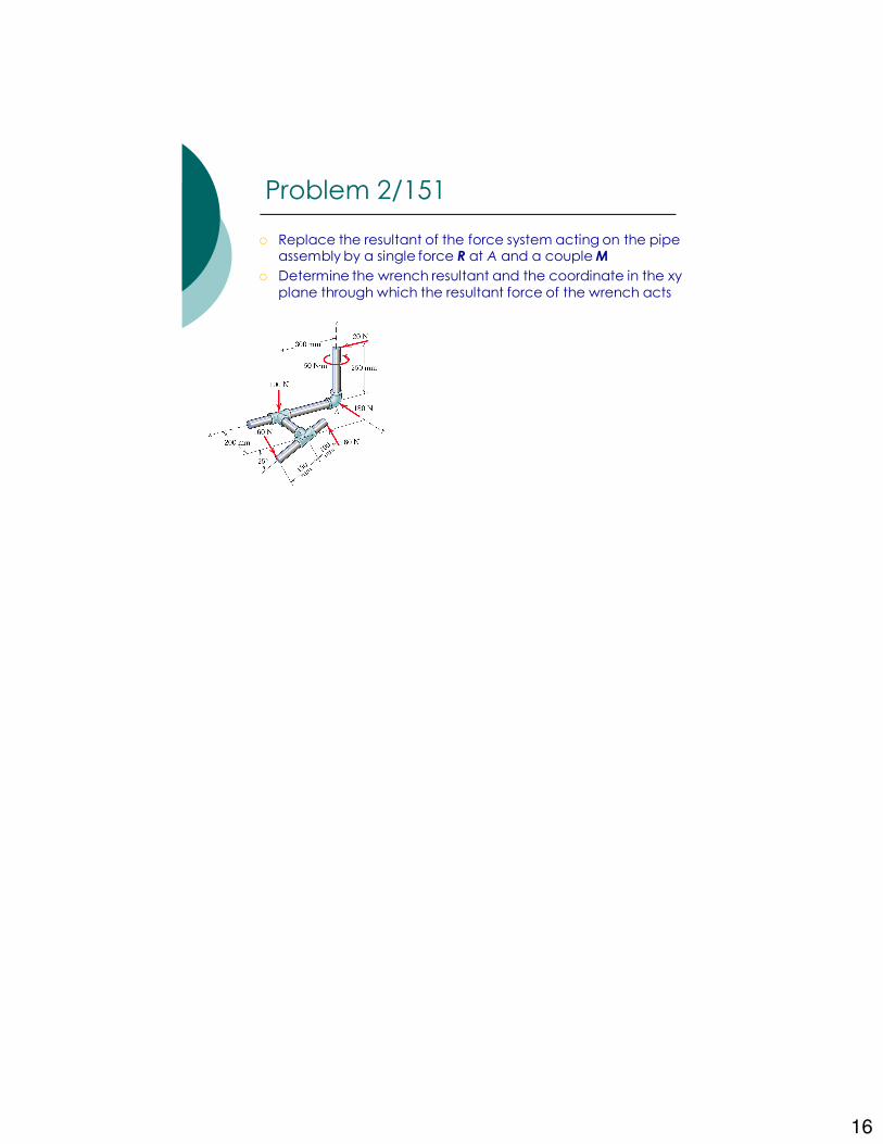
� Replace the resultant of the force system acting on the pipe assembly by a single force R at A and a couple M
� Determine the wrench resultant and the coordinate in the xy plane through which the resultant force of the wrench acts
Problem 2/151