Engineering Mechanics - IIT Bombayminamdar/ce102/Files/Trusses.pdf · Analysis of Trusses by the...
43
Engineering Mechanics Trusses
-
Upload
truongmien -
Category
Documents
-
view
216 -
download
1
Transcript of Engineering Mechanics - IIT Bombayminamdar/ce102/Files/Trusses.pdf · Analysis of Trusses by the...

Engineering Mechanics
Trusses

Truss
2

Definition of a Truss
• A truss is an assembly of straight members connected at joints. No member is continuous through a joint.
• Bolted or welded connections are assumed to be pinned together. Forces acting at the member ends reduce to a single force and no couple. Only two-force members are considered.
• Most structures are made of several trusses joined together to form a space framework. Each truss carries those loads which act in its plane and may be treated as a two-dimensional structure.
• When forces tend to pull the member apart, it is in tension. When the forces tend to compress the member, it is in compression.
3

Definition of a Truss
Members of a truss are slender and not capable of supporting large lateral loads. Loads must be applied at the joints.
• Weights are assumed to be distributed to joints.
• External distributed loads transferred to joints via stringers and floor beams. 4

Definition of a Truss
5
Definition of a Truss
6

Simple Trusses
• A rigid truss will not collapse under the application of a load.
• A simple truss is constructed by successively adding two members and one connection to the basic triangular truss.
• In a simple truss, m = 2j - 3 where m is the total number of members and j is the number of joints.
7

Identify the Simple Trusses
• A simple truss is constructed by successively adding two members and one connection to the basic triangular truss.
• In a simple truss, m = 2j - 3 where m is the total number of members and j is the number of joints. 8

Identify the Simple Trusses
• A simple truss is constructed by successively adding two members and one connection to the basic triangular truss.
• In a simple truss, m = 2j - 3 where m is the total number of members and j is the number of joints.
m = 29 j = 16m = 45 j = 24
9

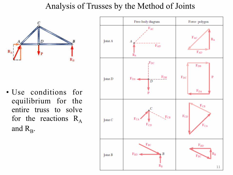
Analysis of Trusses by the Method of Joints
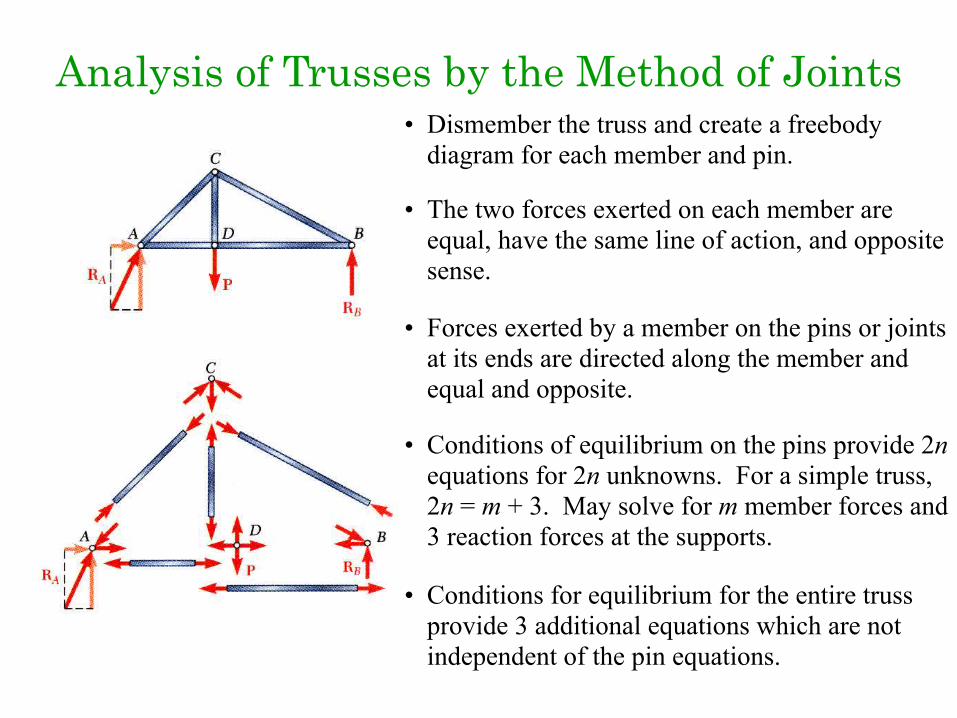
• Dismember the truss and create a free body diagram for each member and pin.
• The two forces exerted on each member are equal, have the same line of action, and opposite sense.
• Forces exerted by a member on the pins or joints at its ends are directed along the member and equal and opposite.
• Conditions of equilibrium on the pins provide 2j equations for 2j unknowns. For a simple truss, 2j = m + 3. May solve for m member forces and 3 reaction forces at the supports.
• Conditions for equilibrium for the entire truss provide 3 additional equations which are not independent of the pin equations. 10
Analysis of Trusses by the Method of Joints
• Use conditions for equilibrium for the entire truss to solve for the reactions RA and RB.
11

Analysis of Trusses by the Method of Joints
Alternate Force Polygon for Joint A
12

Truss Connections and Supports
Riveted, Bolted, or Welded
External and internal (dotted) supports

Method of Joints
Note the direction of the forces in the members acting on the joints

Problem 27 Determine the forces in the members in the following truss
15
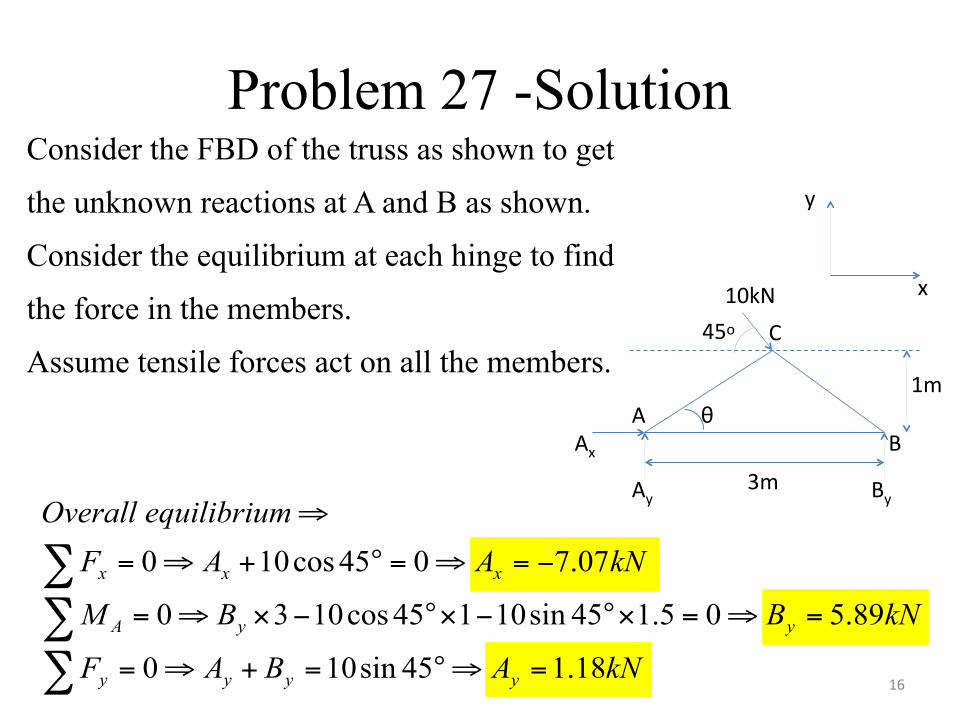
Problem 27 -SolutionConsider the FBD of the truss as shown to get
the unknown reactions at A and B as shown.
Consider the equilibrium at each hinge to find
the force in the members.
Assume tensile forces act on all the members.
10kN45o
1m
3m
Ax
Ay By
C
AB
θ
x
y
kNABAF
kNBBM
kNAAFmequilibriuOverall
yyyy
yyA
xxx
18.145sin100
89.505.145sin10145cos1030
07.7045cos100
=⇒°=+⇒=
=⇒=×°−×°−×⇒=
−=⇒=°+⇒=
⇒
∑∑∑
16
θ
By=5.89kN
BFAB
FBC
θAx=7.07kN
Ay=1.18kN
AFAB
FAC
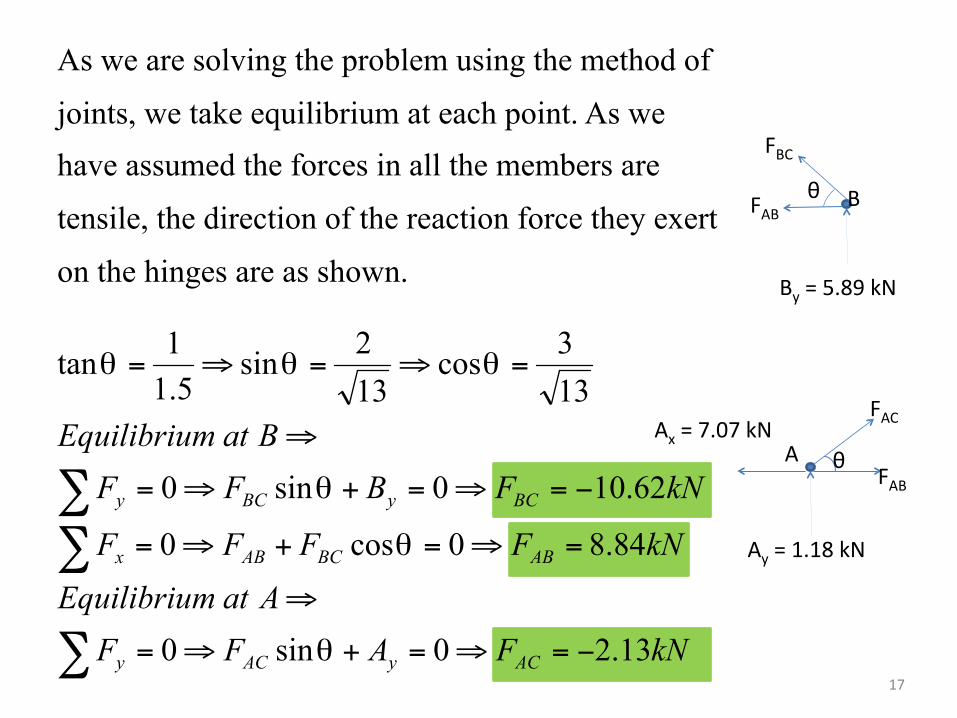
As we are solving the problem using the method of
joints, we take equilibrium at each point. As we have assumed the forces in all the members are
tensile, the direction of the reaction force they exert
on the hinges are as shown.
kNFAFF
AatmEquilibriu
kNFFFF
kNFBFF
BatmEquilibriu
ACyACy
ABBCABx
BCyBCy
13.20sin0
84.80cos0
62.100sin0
133
cos132
sin5.11
tan
−=⇒=+⇒=
⇒
=⇒=+⇒=
−=⇒=+⇒=
⇒
=⇒=⇒=
∑
∑∑
θ
θ
θ
θθθ
17

FAB=8.84kN (T)
FBC=10.62kN (C)
FAC=2.13kN (C)
We assumed that all the forces in the members were tensile.
But we got some of them negative. So, the negative sign
indicates that the forces in the members are compressive.
18
10.62kN
8.84kN
2.13kN
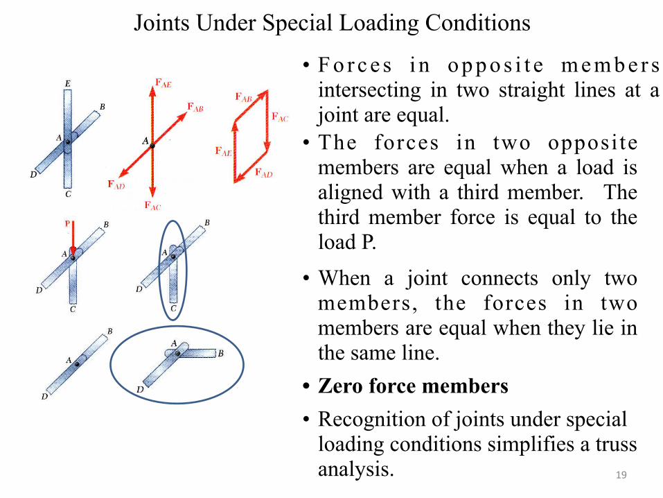
Joints Under Special Loading Conditions
• F o r c e s i n o p p o s i t e m e m b e r s intersecting in two straight lines at a joint are equal.
• The forces in two opposite members are equal when a load is aligned with a third member. The third member force is equal to the load P.
• Zero force members• Recognition of joints under special
loading conditions simplifies a truss analysis.
• When a joint connects only two members, the forces in two members are equal when they lie in the same line.
19

Problem 30 and 31
• For the given loading, determine the zero force members in the trusses shown
20

Problem 30 - Solution
• Joint A is connected to two members and subjected to an external load P oriented along member AB. FAF = 0
• Joint L is connected to three members out of which members LK and LM are in straight lines. FLG = 0
21

Problem 30 - Solution
FCH = 0
FNI = 0
• Joint N is connected to three members out of which members MN and NO are in straight lines.
• Joint C is connected to three members out of which members CB and CD are in straight lines.
22

Problem 30 - Solution
• Joint E is connected to two members which are not in a straight line. FEJ = 0FED = 0
23
Analysis of Trusses by the Method of Joints• Dismember the truss and create a freebody
diagram for each member and pin.
• The two forces exerted on each member are equal, have the same line of action, and opposite sense.
• Forces exerted by a member on the pins or joints at its ends are directed along the member and equal and opposite.
• Conditions of equilibrium on the pins provide 2n equations for 2n unknowns. For a simple truss, 2n = m + 3. May solve for m member forces and 3 reaction forces at the supports.
• Conditions for equilibrium for the entire truss provide 3 additional equations which are not independent of the pin equations.

Special Loading Conditions• Can be recognized by using specialized
co-ordinate axes
Analysis of Trusses by the Method of Sections
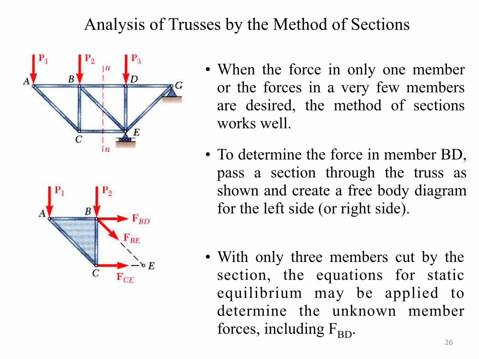
• When the force in only one member or the forces in a very few members are desired, the method of sections works well.
• To determine the force in member BD, pass a section through the truss as shown and create a free body diagram for the left side (or right side).
• With only three members cut by the section, the equations for static equilibrium may be applied to determine the unknown member forces, including FBD.
26

Problem 1• Using method of joints, determine the forces in
the members of the trusses shown
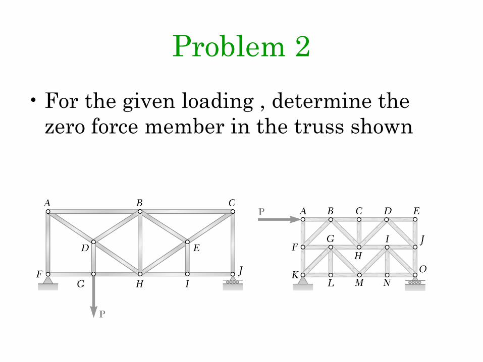
Problem 2• For the given loading , determine the
zero force member in the truss shown

Problem 5• Find the forces in members EF, KL, and
GL for the Fink truss shown. You can use combination of joints + sections.
EF = 75.1 kN (C), KL = 40 kN (T), GL = 20 kN (T)
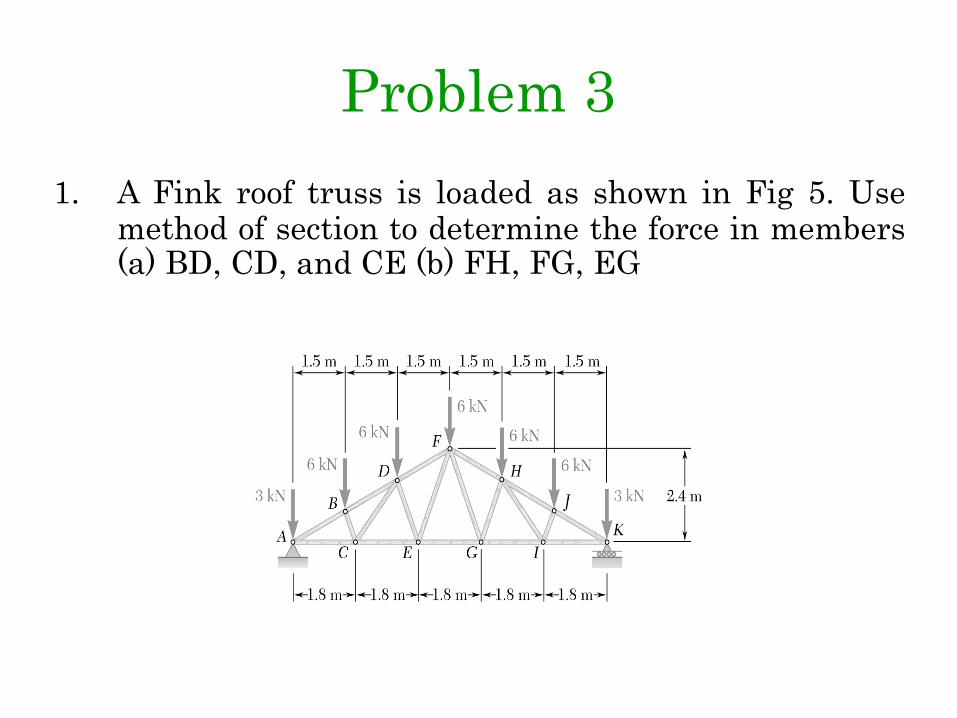
Problem 31. A Fink roof truss is loaded as shown in Fig 5. Use
method of section to determine the force in members (a) BD, CD, and CE (b) FH, FG, EG

Problem 4• Use method of section to determine the
force in members IK, HK, FI, EG of the truss shown in the figure.

Problem 6• The truss supports a ramp (shown with a dashed line) which
extends from a fixed approach level near joint F to a fixed exit level near J. The loads shown represent the weight of the ramp. Determine the forces in members BH and CD.
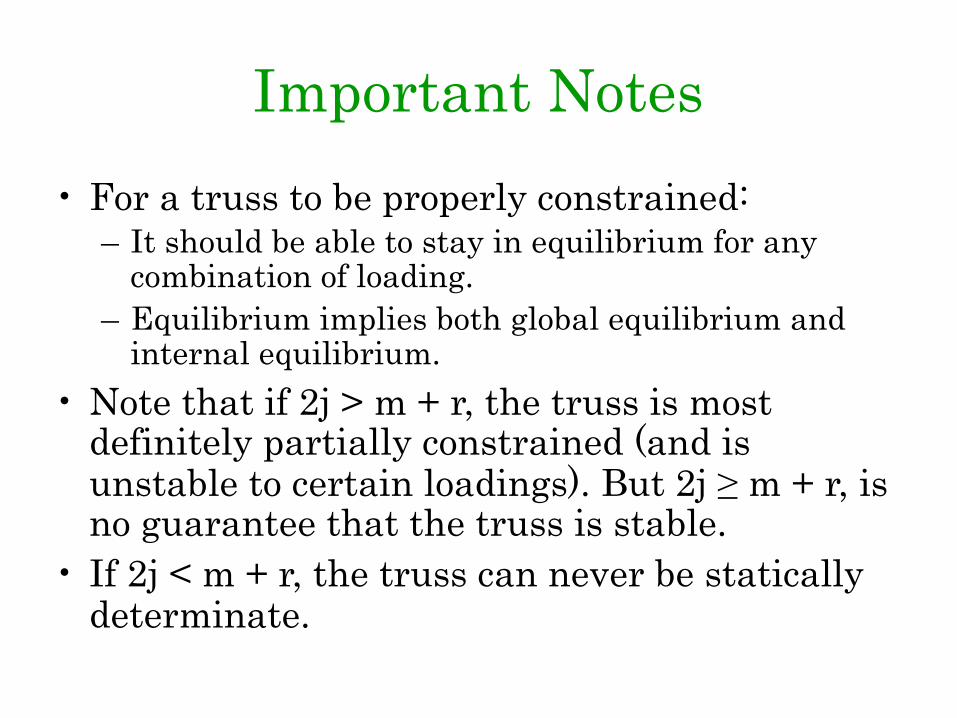
Important Notes• For a truss to be properly constrained:
– It should be able to stay in equilibrium for any combination of loading.
– Equilibrium implies both global equilibrium and internal equilibrium.
• Note that if 2j > m + r, the truss is most definitely partially constrained (and is unstable to certain loadings). But 2j ≥ m + r, is no guarantee that the truss is stable.
• If 2j < m + r, the truss can never be statically determinate.

Problem 7• Determine the forces in bars 1. 2. and 3 of the
plane truss supported and loaded as shown in the figure
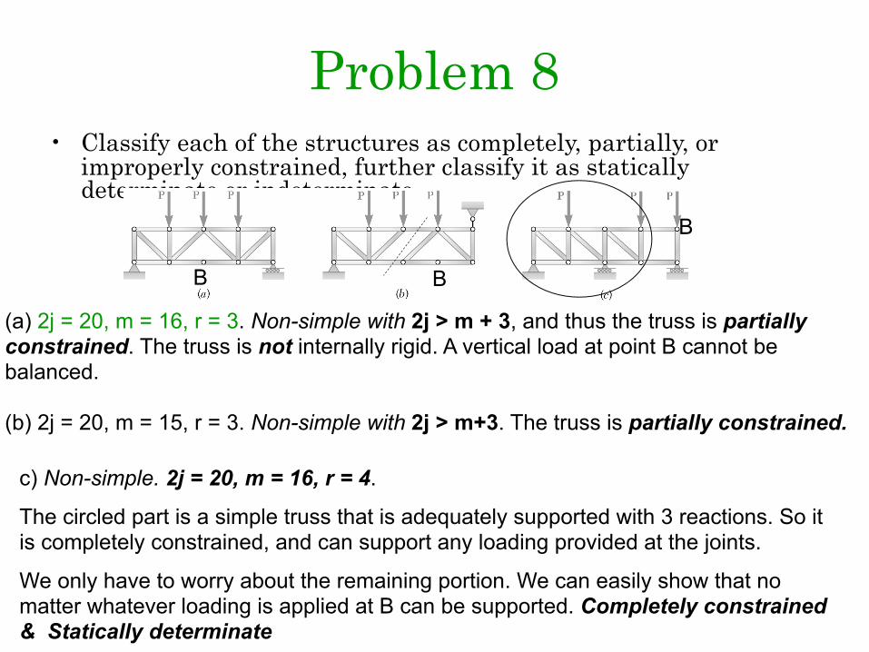
Problem 8• Classify each of the structures as completely, partially, or
improperly constrained, further classify it as statically determinate or indeterminate.
(a) 2j = 20, m = 16, r = 3. Non-simple with 2j > m + 3, and thus the truss is partially constrained. The truss is not internally rigid. A vertical load at point B cannot be balanced.
B
(b) 2j = 20, m = 15, r = 3. Non-simple with 2j > m+3. The truss is partially constrained.
B
c) Non-simple. 2j = 20, m = 16, r = 4.
The circled part is a simple truss that is adequately supported with 3 reactions. So it is completely constrained, and can support any loading provided at the joints.
We only have to worry about the remaining portion. We can easily show that no matter whatever loading is applied at B can be supported. Completely constrained & Statically determinate
B

Problem 8• Classify each of the structures as completely, partially, or
improperly constrained, further classify it as statically determinate or indeterminate.
(a) Simple truss with four more than adequate supports. Internally rigid, externally over-supported. j = 9, m = 13, r = 4. 2j < m + r, so Completely Constrained & Statically indeterminate.
(b) j = 10, m = 16, r = 4, 2j = m + r. Circled truss is simple truss which has enough reactions for global equilibrium. Thus it is completely constrained. The second truss is also simple and has three external reactions. Thus is also completely constrained. Completely constrained & Statically determinate.
c) j = 9, m = 13, r = 4, 2j < m + r. Incompletely constrained.

Problem 8• Classify each of the structures as completely, partially, or
improperly constrained, further classify it as statically determinate or indeterminate.
(a) j = 8, m = 12, r = 4, 2j = m + r. Seemingly the truss is completely constrained. The circled portion is simple and adequately constrained with 3 reactions. The remaining portion can take care of any loading. Also not possible to deform the parallelogram. Completely constrained.
(b) j = 8, m = 12, r = 3, 2j > m + r. Partially Constrained

Problem 8
a)j = 8, m = 12, r = 4, 2j = m + r. But note that for the left truss, moment balance about B is not obeyed. So the truss is Improperly constrained
B
b) j = 7, m = 10, r = 3, 2j > m + r. Partially Constrained
c) j = 8, r = 3, m = 13, 2j = m + r. Clearly the truss cannot be equilibrium with this loading. Can be understood by equilibrium of joint B and C. Can also be understood by taking a section as shown. Improperly Constrained.
B C

Problem 1• Determine the forces in members FH, EH, EG,
LM, MK and LK.
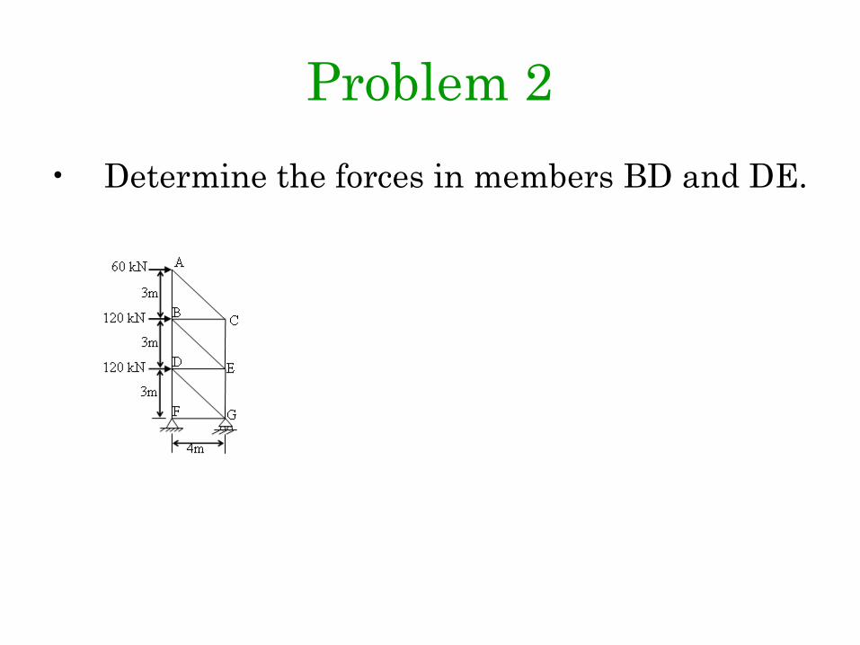
Problem 2• Determine the forces in members BD and DE.

Problem 3• Determine the forces in members in AB, BC, AD, and AE.

Problem 4• Determine the forces in members AK, KE, and
CE.