engineeRing / installation Compounding of RubbeR … · Variety of Materials as Rubber. Compounding...
47
CONTENTS Compounding of Rubber ........................................................................................................................... 45 Custom Mixing ......................................................................................................................................... 46 Effects of Oil on Rubber ........................................................................................................................... 47 Chemical Resistance .................................................................................................................................. 48 Physical Testing-Rubber ............................................................................................................................ 49 Effect of Heat ............................................................................................................................................ 50 Fabric Specifications ............................................................................................................................ 51-52 Fabric Testing .......................................................................................................................................... 53 Foreign Fabrics ........................................................................................................................................ 54 More About Textiles ............................................................................................................................... 55 Adhesions.................................................................................................................................................. 56 Conveyor Belt Grades .............................................................................................................................. 57 Conveyor Design ................................................................................................................................. 58-59 Elevator Belt . ...................................................................................................................................... 60-62 Engineering .......................................................................................................................................... 63-64 Compound Specifications .......................................................................................................................... 65 Storage ....................................................................................................................................................... 66 Handling .................................................................................................................................................... 67 Installation ................................................................................................................................................. 68 Training ..................................................................................................................................................... 69 Training Sequence ..................................................................................................................................... 68 Loading.................................................................................................................................................. 70-71 Load Support .............................................................................................................................................. 72 Transition.............................................................................................................................................. 73-74 Pulley Diameter ......................................................................................................................................... 75 Squaring ..................................................................................................................................................... 76 Vulcanizing ........................................................................................................................................... 77-80 Step Lengths .............................................................................................................................................. 82 Cure Rates ............................................................................................................................................. 83-84 Trouble Shooting .................................................................................................................................. 85-87 Conveyor Calculation ............................................................................................................................... 88 Calculation Notes ...................................................................................................................................... 89 Patents & Warranty................................................................................................................................... 90 ENGINEERING / INSTALLATION & TROUBLE SHOOTING Montgomery, Alabama USA 1•800 •633 •1470 • Fax: 334 •271•3194 www.pricerubber.com
Transcript of engineeRing / installation Compounding of RubbeR … · Variety of Materials as Rubber. Compounding...

44
Compounding of RubbeR
Contents Compounding of Rubber ........................................................................................................................... 45Custom Mixing ......................................................................................................................................... 46Effects of Oil on Rubber ........................................................................................................................... 47Chemical Resistance .................................................................................................................................. 48Physical Testing-Rubber ............................................................................................................................ 49Effect of Heat ............................................................................................................................................ 50Fabric Specifications ............................................................................................................................ 51-52Fabric Testing .......................................................................................................................................... 53Foreign Fabrics ........................................................................................................................................ 54More About Textiles ............................................................................................................................... 55Adhesions .................................................................................................................................................. 56Conveyor Belt Grades .............................................................................................................................. 57Conveyor Design ................................................................................................................................. 58-59Elevator Belt . ...................................................................................................................................... 60-62Engineering .......................................................................................................................................... 63-64Compound Specifications .......................................................................................................................... 65Storage ....................................................................................................................................................... 66Handling .................................................................................................................................................... 67Installation ................................................................................................................................................. 68Training ..................................................................................................................................................... 69Training Sequence ..................................................................................................................................... 68Loading ..................................................................................................................................................70-71Load Support .............................................................................................................................................. 72Transition ..............................................................................................................................................73-74Pulley Diameter ......................................................................................................................................... 75Squaring ..................................................................................................................................................... 76Vulcanizing ...........................................................................................................................................77-80Step Lengths .............................................................................................................................................. 82Cure Rates .............................................................................................................................................83-84Trouble Shooting ..................................................................................................................................85-87Conveyor Calculation ............................................................................................................................... 88Calculation Notes ...................................................................................................................................... 89
Patents & Warranty ................................................................................................................................... 90
engineeRing / installation
& tRouble shooting
Montgomery, Alabama USA1•800•633•1470 • Fax: 334•271•3194
www.pricerubber.com

45
Carbon black is the most commonly used ingredient in all black rubber recipes, because it reinforces rubber to make it tougher and more abrasion and crack (fatigue) resistant. Carbon is chosen from a wide range of sizes and grades to suit the end product. Carbon is heavy (Sp. gr. 1.6).
Clays are used extensively in rubber to improve serviceability, modify elongation, hardness, stiffness and specific gravity. Generally, they are cheap but heavy (Sp. gr. 2.6) and must be used in limited quantities, not to impede tensile strength, tear resistance or resistance to abrasion.
Oils & Waxes are considered extenders. They are chosen to improve processability, a smoother product and to decrease cost, as most oils are cheaper than rubbers.
Coloring, Antioxidants, Accelerators & Vulcanizing Agents are chosen to suit the intended use of the finished product.
Probably no Other Industry Uses as Great aVariety of Materials as Rubber.
Compounding of Rubber is much like a bakery . . . the recipe is designed to suit theintended end use of the product.
The rubber (elastomer) is chosen for abrasion, resistance to heat or oils, cold weather flexing or resistance to sunlight, ozone or electrical fields. Oftentimes, two or more rubbers are blended to gain the natural advantages of each. But these rubbers are not serviceable by themselves, and must be blended with fillers, oils, plasticizers, waxes, coloring agents and vulcanizing chemicals.
Common
Elastomers
Common
Fillers Common
Oils
Compounding of RubbeR
+

46
effeCts of oil on RubbeR Custom mixing
Rubbers Sp. Gr Butyl .92 EPDM .86 Hypalon 1.10 Mineral 1.04 Natural .92 Neoprene 1.23 Nitrile 1.00 Polybutadiene .94 Syn. Natural .92 SBR .94 Silicone .98 Thiokol 1.27
Fillers Sp. Gr. AI. Hydrate 2.42 Barytes 4.45 Ca. Carbonate 2.70 C. Black 1.80 Clays 2.60 Graphite 2.25 Kaolin 2.60 Lime 2.20 Mg. Carbonate 2.22 Mica 2.95 Soapstone 2.72 Talc 2.72 Titanium Di. 3.93
Processing Sp.Gr. Aids
Carnauba Wax .99 DOP Oil .98 Factice 1.06 Mineral Oil .84 Pine Oil .93 Tall Oil .98 Parafin Wax .90 Petrolatum .84 Pine Tar 1.08 Rosin 1.08
Vulcanizers Sp.Gr. Mg. Oxide 3.32 Sulfur 2.07 Zn Oxide 5.57
Chosento suit the finished product
Accelerator Activators to assist accelerators
Age-Resistors to retard deterioration from oxygen, heat, light, ozone
Miscellaneous retarders, colors, blowing aids, abrasives, dusting agents, odorants
Fillers carbons and clays
Softeners for mixing, tack, elasticity
Processing Aids oils, plasticisersand waxes
Vulcanizing AgentsSuch as Sulfur for crosslinking
Acceleratorsto hasten cure
Miscellaneous Sp.Gr. Am. Bicarbonate 1.58 Asbestos 2.47 Coal Tar 1.18 Cork .80 Cotton Flock 1.25 Gelatin 1.27 Rubber Dust 1.20 Iron Oxide 5.14 Lead 11.34 Lignin 1.30 Mg. Carbonate 2.22 Castor Oil .96 Cotton Seed Oil .92 Palm Oil .88 Pumice 2.35 Shellac 1.10 Sodium Bicarbonate 2.20 Stearic Acid .85 Urea 1.34 Whiting 2.62 Wood Flour 1.25 Zinc Stearate. 1.05Air
OperatedRam
DropDischarge Door
MixingRotors
Like a bakery, thousands of recipes are written around hundreds of ingredients, each intended to contribute something to the finished product. Rubber can be made soft orhard, flexible or rigid, elastic or tough, alive or dead-liquid, sponge, almost any color and resistant to sunlight, electrical current, sub-zero temperature, heat, and many chemicals and oils.
LoadingHopper
Natural
Rubber
Synt
hetic
Rub
ber

47
effeCts of oil on RubbeR
Petroleum
Wheat
Corn
Generally, oils, fats and greases will cause rubbers to swell, become tender and soften. To retard this action, rubbers are combined with other elements. The two most commonly used oil resistant rubbers are Neoprene (chloroprene) and Nitrile (acrylonitrile). Cl CH2 = C - CH = CH2 (Chloroprene)
Neoprene - Has an occasional Chlorine atom on the molecular chain, which stabilizes the rubber against attack of petroleum based products better than most common rubbers. Though effective against animal and vegetable fats, Nitrile is even better and generally more cost effective.
H (Acrylonitrile) C = C H C = N
Nitrile - Has an atom of Nitrogen on the molecular chain that retards attack of oils, particularly animal and vegetable.
Pine and Fir (Conifers) oils and resins are handled by Nitrile rubbers in moderate blends with other rubbers.
Both Neoprene and Nitrile rubbers may be blended in almost any degree with other rubbers
to achieve the desired level of oil resistance.
Soybeans
Custom mixing

48
physiCal testing -RubbeR ChemiCal ResistanCe of RubbeRs
Most rubber compounds will resist moderate concentrations of alkaline materials (bases). However, Resorcinol-Formaldehyde-Latex (RFL) fabric treatments may be destroyed by hydroxide solutions.
Specific applications may be laboratorychecked for the best rubberrecommendation.
Ask for assistance in choosing the mostsuitable rubber for specialcircumstances.
Alkaline - A base is the
hydroxide (OH)
14.0 of a metal.
13.0
12.0 + water
11.0 EPDM 10.0 Dry Chemicals Nitrile
9.0 Salts A salt is a metal SBR combined with an
Natural 8.0 Alcohols acid radical.
Pure Water pH 7.0 Neutral
SBR
Natural 6.0 Mild Acids
Neoprene 5.0 Organic Solvents + an active metal
EPDM
Butyl 4.0 Moderate Acids
Hypalon 3.0
2.0
1.0
pH Scale Acid - A hydrogen compound whose water solution containshydrogen ions. Free hydrogen ion concentrations in strong acidswill attack most rubber compounds. In conveying, many materialswill combine with atmospheric moisture to form these acids.
s
s
Chemical alterations of rubber depend upon chemical concentration, temperature and availability of water or other solvents
to carry reactions forward.

49
physiCal testing -RubbeR
Tensile is a measure of force required to break a material. In rubber, generally a dumbbell sample with a 1/4'' x 1/4'' cross section (neck) is broken and pounds per square inch are calculated.
Elongation is the ‘’stretch’’ of a material at break, expressed as a percent of the relaxed original. Modulus is a measure of force required to stretch a materiala particular amount. In rubber, generally a sample is stretched 300% and the necessary force (pounds per square inch) is calculated. Durometer is a measure of hardness, measured with a plunger and read on a gauge. A rubber band might read 35, a tire tread about 60 and a shoe heel about 70 durometer.
Modulus of Elasticity is the same as modulus, but sometimes offered as a mathematical (calcu-lated) expression of the forces in a composite material, such as conveyor belt, as it ‘’curves’’ up or down a troughed conveyor system. The figures far exceed any force the belt would with-stand in actual use, and they serve no practical application in conveyor belt design, other than to compare one set of numbers with another.
Abrasion is wear from scuffing. Pico Abrasion is a method of measuring the wear of rubber by scraping a sample with keen knife blades and weighing the sample at the end of a specified time. The higher the number, the less material is abraded away, and the more abrasion resistant the sample is believed to be. No claim is made for validity.
Dumbbell
Original Length
1''
4''
Modulus at 300% Elongation
Tensile measured at break
s
s
sSample
1/4
x 1/
4 T
est
Sect
ion
ChemiCal ResistanCe of RubbeRs

50
effeCt of heat
Belt fabrics are used
at 1/10th of break
strength because
elongation makes
them unusable
above that rating.

51
fabRiC speCifiCations
Weight Tensile Count Gauge Fabric Grams per Ozs. per kg Pounds Ends Ends Thdths. Thdths. No. Sq. Mtr. Sq. yd. per cm. per inch per cm. per inch mm inches
75 426 12.6 140 x 105 785 x 585 18.5 x 6.9 47 x 17.5 .584 .023
90 541 16.0 193 x 113 1080 x 630 12.5 x 3.9 31 x 10 .781 .031
110 609 18.0 215 x 132 1200 x 740 13.8 x 4.7 35 x 12 .838 .033
125 704 20.8 241 x 94 1350 x 525 10.2 x 5.1 26 x 13 .939 .037
150 863 25.5 268 x 161 1500 x 900 10.2 x 5.9 26 x 15 1.245 .049
200 971 28.7 360 x 164 2010 x 916 9.3 x 4.3 23.5 x 11 1.321 .052
250 1194 35.3 447 x 157 2500 x 875 15.7 x 5.3 4 0 x 13.5 1.626 .064
300 1330 39.3 555 x 157 3100 x 875 18.1 x 5.3 46 x 13.5 1.651 .065
Multi - Ply (Plain Weave) Polyester / Nylon
EP100 355 10.5 125 x 63 700 x 353 11.8 x 6.7 30 x 17 .53 .021
EP125 430 12.7 165 x 65 924 x 364 19.7 x 6.5 5.0 x 16.5 .70 .028
EP160 560 16.5 210 x 80 1176 x 448 10.0 x 4.5 25.5 x 11.5 .90 .035
EP200 690 20.4 250 x 1001 1400 x 560 9.4 x 3.9 24 x 10 1.05 .041
EP250 860 25.4 310 x 100 1736 x 560 8.3 x 3.9 21 x 10 1.21 .047
Fabric Styles
Polyester
EP FabricsPolyester/Nylon
s
s
Multi -Ply / Straight Warp / Polyester or Polyester-Nylon
effeCt of heat

52
fabRiC testing fabRiC speCifiCations
Conveyor Belt Fabrics usually are cataloged according to intended use strengths... a 110 lb. fabric is intended to be used at working tensions not greater than 110 lbs. per inch of width, per ply. Customarily, such 110 lb. fabric will have a breaking strength of 10 x allowable working tension (AWT), but sometimes a 7:1 or even less ‘’safety factor’’ is used.
This 10:1 limit of AWT to ultimate breaking strength is felt necessary to avoid excessive stretch and ‘’necking down’’ of the fabric at loads greater than 1/10 th of break. While the fabric will not break until a load of 10 x the AWT is applied to it, it will begin to change shape severely (neck down) and the fibers or strands will begin to elongate or slip... the fabric gets weaker and weaker as it grows longer and longer. Though break may not occur for quite awhile, the product will be stretched far beyond practical use long before it breaks... maybe even 300% to 400% of the original length.
Weight of a fabric generally is per square yard, 36'' x 36'', though sometimes a 42'' x 36'', measure is used.
Gauge is overall thickness of fabric usually in thousandths of an inch.
Tensile is the ultimate breaking strength of a fabric, per inch of width, either lengthwise (warp) or crosswise (weft). This tensile can be Calculated by multiplying the number of yarns per inch by the tensile of each yarn. Or, it may be measured by either the Ravel Method or the Grab Method.

53
fabRiC testing
In the Ravel Method, a strip of fabric 1-1/4'' wide x 6'' long is raveled at the edges by removing a few strands until the test strip is 1'' wide. These longer cross strands (weft) are expected to provide a more accurate measurement than a strip that is 1'' x 6''. Jaws 2'' wide are used to make this test.
In the Grab Method, a strip 4'' wide x 6'' long is pulled with 1'' jaws, but a slightly higher reading is expected than in the ravel method because of the outside strands that add some to the fabric tensile. Either method is used to test fabric, either lengthwise or crosswise.
Count is the number of strands per inch of width, either warp (lengthwise) or weft (crosswise).
Conveyor Belt Fabrics are available in a wide variety of materials, woven into many different styles from many combinations of twists and plies. Today, most such fabrics are made from Polyester or Nylon, or some combination of the two. Lighter fabrics are sometimes made from Cotton or other synthetics.
fabRiC speCifiCations

54
moRe about textiles
Since Conveyor Belt is an ‘’international product,’’ it is necessary to compare the fabric ratings used in various areas of the world. Direct comparison of fabrics by number is misleading because the figures are not uniform, one area to another, and do not indicate equal strengths of the fabrics. Allowable Working Tension (AWT) is approximately 33-1/3% of Asian (NN) numbers, and approximately 70% of European (EP) numbers, compared with American numbers.
Foreigners coat their fabrics with a layer of rubber before tensile tests are made, but do not specify the thickness nor the type of rubber used. Figures represent the strength of the fabric in the finished belt, after having been down-graded by 25% from exposure to heat during vulcanization.
However Asian belt fabrics are downgraded to 75% of these calculated strengths when built into a multiple belt carcass. Asians and Europeans rate the fabric in the finished belt. A three ply belt made from NN-300 (a 140 lb. fabric) is rated at 105 lbs. per ply in the finished belt. This compares with the EP160 designation in Europe, and with 110 in America.
American fabrics are measured in pounds per inch and are considered the same strength when placed in a belt. The belt carcass is a simple multiple of the number of plies times the fabric weight, with no adjustment made for rubber layers or for heat degradation.
Designated generally as ‘’EP’’ fabrics, European fabrics are made from Polyester and Nylon. Asians use ‘’NN’’ to suggest Nylon-Nylon construction of warp and filler. In addition, Asians reduce fabric strengths by up to 50% in belts subjected to temperatures of 180 deg. C (356 deg. F). American fabrics are not down-graded in this heat range.
Asian European* American*
Fabric AWT Fabric AWT Fabric AWT Number Lbs. / In. Number Lbs. / In. Number Lbs. / In. 100% 75% NN-100 46 34 – – – – NN-120 56 42 NN-125 58 44 – – – – NN-150 70 52 – – – – NN-160 78 58 – – 60 60 NN-200 93 75 EP 100 70 75 75 NN-250 116 87 EP 125 90 90 90 NN-300 140 105 EP 160 110 110 110 NN-350 163 122 – – – – NN-400 186 139 EP 200 140 – – –√ – – – – 150 150 NN-500 234 175 EP 250 175 – – NN-600 280 210 200 200 – – – – – 250 250 – – – – – 300 300*See page 50 for complete specifications.
foReign fabRiCs vs. ameRiCan

55
moRe about textiles
Denier is a unit of weight of a yarn. 9,000 meters weighing one gram is one denier, or 15 denier yarn weighs 15 grams per 9,000 meters (.529 ounces per 29,520 feet or 5.59 miles).
Carding arranges fibers into a loose rope called a sliver. Many slivers may be drawn together to form a thin strand called a roving. This roving is twisted on a spinning frame to form yarn.
Yarn may be formed from blended fibers at carding, from blended slivers when drawn together, or from blended rovings as the yarn is spun.
Plies are formed by twisting two or more yarns together. Spools of yarns are placed in a rack called a creel and wound onto a larger spool called a beam that is placed on the loom to be fed off as the warp (lengthwise) strands of the fabric.
Weft / (crosswise) yarns are wound on shuttles and passed through the warp yarns as the loom harness raises and lowers various warp yarns to form the fabric weave.
Plain weaves are formed by passing the weft strand over and under each warp strand.
Twill weaves are formed by passing the weft strand over and under 2,3 or 4 warp yarns, with each row beginning slightly to the right or left of the previous row.
Here are some common industrial fabric weaves.
foReign fabRiCs vs. ameRiCan
Straight
Warp
Crow
Foot
Plain
Weave
Twill
Weave

56
ConveyoR belt gRadesadhesions
Today, modern belt adhesions are performed by computerized-electromechanical testers which are used to measure & record the force necessary to separate cover to carcass plies, usually in pounds per inch of width (PIW). This information is critical in deciding upon the quality of a product, and the expected life in actual use.
In conveyor belting, common SBR (Styrene-Butadiene Rubbers) are compounded to yield an adhesion between covers and plies in the 60 to 70 lb. range, while Nitriles, EPDM, Coal stocks and Chlorobutyl will measure somewhat less. Natural rubber compounds, high grade truck tread stocks and specially treated fabrics can produce test figures as high as 150 to 200 lbs. per inch of width, measured on Instron Test Systems.
Industrial hoses usually are made with lower adhesions, as are OEM tires, where tests as low as 24 lbs. per inch of width may be considered adequate. As a rule, thicker rubber compounds will produce higher adhesions, both between the rubbers and between rubber and metal, fabric, or plastic. Thin rubber layers do not test as well.
Adhesion is firm or steady contact between two surfaces. In rubber, generally it applies to the ‘’grab’’ of rubber to rubber or rubber to metal, fabric, plastics or other components of a finished product. Because most synthetic fabrics are slick and will not stick to most rubber compounds, it is necessary to treat these fabrics with a ‘’go-between.’’
RFL (Resorcinol-Formaldehyde -Latex) is the most commonly used treatment for rubber to fabric adhesions, but sometimes other coatings such as special resins or isocyanates must be used. This RFL coating is applied at the fabric mill, where the fabric is dried and heat set at the same time.
Heat Setting of fabric is done in the 325 to 375 degree F. range while under tension. Such heating can shrink Nylon and Polyesters as much as 15% from woven dimensions, both width and length. This heat shrink must be considered throughout the manufacturing process.
RFL Dipping Process
Fabric RFL Dry/Cure Ovens Take Up
From the
Final Treatment to
*Instron 10 kN Adhesion / Stress Testor
Greige
rr

57
The RMA (Rubber Manufacturer’s Association) established specifications for conveyor belt grades several decades ago. Though many of the early members of that association are no longer manufacturing belting, those standards have been passed along with suitable changes to accommodate more ‘’modern’’ raw materials presently used in belt work. Only commonly used belts in general industrial applications are graded as to rubber (generally SBR, natural or a combination), though the carcass fabrics are essentially the same when covered by specialty rubbers such as Neoprene, Nitrile or Chlorobutyl. The standards for the three grades of general purpose belts were:
RMA Original Specifications RMA 1994 Specifications RMA Grade #1 - Cover tensiles of 3500 to 4000 Ibs. Adhesion between components of 20 to 24 Ibs. RMA Grade #2 - Cover tensiles of 2500 to 3000 Ibs. Adhesion between components of 16 to 19 Ibs. RMA Grade #3 - Cover tensiles of 800 to 1000 Ibs. Adhesion between components of 12 to 15 Ibs.
RMA Grade #1 - Cover tensiles of 2500 Ibs. 400% elongation.
RMA Grade #2 - Cover tensiles of 2000 Ibs. 400% elongation.
RMA Grade #3 - No specifications.
ConveyoR belt gRades
Because Cotton was the basic carcass material when these standards were established, adhesions were more difficult at the time. Today, with synthetic fabrics and RFL treatments, average adhesions would be in the 60 to 70 lb. range on most general purpose belts. Though cover tensile specifications have been clouded by the introduction of more ‘’modern’’ rubbers, such as EBR (Polybutadiene), there is little justification for relaxing the tensiles first prescribed, other than to reserve for the manufacturer the freedom of using lesser rubbers without criticism.
continues to recognize these original specifications, and publishes complete details of all components. The comparative grades of belts common in the general industry are shown on the Reference Chart contained in this engineering guide, with currently marketed trade names of various belts in each of these three categories. Other specialty belts are listed as well, with original RMA classifica-tions and trade names, but specifications never have been as clear as with Grades #1, #2, and #3. The Consumer is urged to insist upon details on any belt product purchased, so that the grade may be determined, and the suitability of the product for the intended application may be judged.
adhesions

58
ConveyoR design
Supply as many details (?) as you can.The factory can match and suggest specifications for the balance of the conveyor design figures.
Discharge incenter of belt, indirection oftravel.Fall ?____feet.
Loading impact area
Transition (trough forming)
Troughing Idlers
area. Degree?______.
Tail pulley Size?_____inches. Mechanical or hydraulic takeup
Return Idlers
(?) _______ (?) _______ (?) ________
Loading chute
Computer generated conveyor design figures are available from the factory 1•800•633•1470. With a few basic design numbers, the correct belt can be suggested immediately.
Width x Length x Speed
(inches) (C:C feet) (feet per minute) Belt must Almost limitless, Usually 350 to 600 fpm. trough com- properly designed. Sometimes much faster. pletely to be trainable.
& teRminology

59
& teRminology
Type of Drive
Pulley Plain (?) Lagged (?)
Deg. of Wrap 180 (?) __________ 180 (?) _________ Snubbed 210 (?) __________ 210 (?) _________ Tandem 420 (?) __________ 420 (?) _________
Transition area where Head pulley trough flattens out Size ?_____inches.
Lift ?_______feet
Size ?______inches.
Size ?______inches. Gravity Takeup
To accommo- date thermal expansion and Size ?_____inches. prevent drive pulley slippage.
Weight ?______lbs. Center to Center
(?) _______ (?) _______ (?) _______ (?) ________
Material Wt. x Lift 4 Horsepower Carcass Strength
(lbs. / cu. ft.) (feet) A high user of The most ‘’energy Maximum available Carcass must horsepower hungry’’ conveyor horsepower must be accommodate the on heavy feature! considered in choice maximum horsepower materials of belt. or load possible.
60
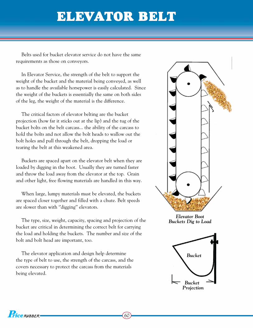
Belts used for bucket elevator service do not have the same requirements as those on conveyors.
In Elevator Service, the strength of the belt to support the weight of the bucket and the material being conveyed, as well as to handle the available horsepower is easily calculated. Since the weight of the buckets is essentially the same on both sides of the leg, the weight of the material is the difference.
The critical factors of elevator belting are the bucket projection (how far it sticks out at the lip) and the tug of the bucket bolts on the belt carcass... the ability of the carcass to hold the bolts and not allow the bolt heads to wallow out the bolt holes and pull through the belt, dropping the load or tearing the belt at this weakened area.
Buckets are spaced apart on the elevator belt when they are loaded by digging in the boot. Usually they are turned faster and throw the load away from the elevator at the top. Grain and other light, free flowing materials are handled in this way.
When large, lumpy materials must be elevated, the buckets are spaced closer together and filled with a chute. Belt speeds are slower than with ‘’digging’’ elevators.
The type, size, weight, capacity, spacing and projection of the bucket are critical in determining the correct belt for carrying the load and holding the buckets. The number and size of the bolt and bolt head are important, too.
The elevator application and design help determine the type of belt to use, the strength of the carcass, and the covers necessary to protect the carcass from the materials being elevated.
Elevator BootBuckets Dig to Load
Bucket
Bucket
Projection
elevatoR belt elevatoR belt

61
elevatoR belt
The selection of a suitable elevator belt depends upon many factors. The factory can help with the proper choice. Get all information shown below for factory help.
See page for standard bucket hole punching.
Splicing of elevator belts should be done with the buckets mounted and the belt drawn tight. Vulcanized splices run the smoothest, but mechanical joints will serve well if properly done.
Material elevated: Weight? __________________ Size? _____________________ Temp.? ___________________Number ofBuckets? _____________________Belt Speed? __________________Leg Height? __________________Horsepower? _________________Pulley Sizes? _________________Bucket Spacing? ______________Type of Bucket? ______________Bucket Weight? _______________Punching Pattern? _____________Number of Bolts? _____________Bolt Size? ____________________Type of Splice? _______________
Loading Chute
Lap - Butt - Clamp - thin belt heavy belt thin belt
Plate fasteners - Vulcanized - thin belt any belt
Types of Splices . . .
elevatoR belt
62

62
hp1
hp2
hp3
hole punch
sizing
punChing
Standard Elevator Bucket Punching
5 x 4 P-1 2 3-3/16 9/32 1/4 6 x 4 P-1 2 4-3/8 9/32 1/4 6 x 5 P-1 2 4-3/8 9/32 1/4
7 x 4 P-2 3 2-11/16 9/32 1/4 8 x 4 P-2 3 3-1/16 9/32 1/4 9 x 4 P-2 3 3-5/8 9/32 1/4 7 x 4-1/2 P-2 3 2-11/16 9/32 1/4 7 x 5 P-2 3 2-11/16 9/32 1/4 8 x 5 P-2 3 3-1/16 9/32 1/4 9 x 5 P-2 3 3-5/8 9/32 1/410 x 5 P-2 3 4-1/8 9/32 1/4 10 x 5-1/2 P-2 3 4-1/8 9/32 1/4 8 x 6 P-2 3 3-1/16 9/32 1/4 9 x 6 P-2 3 3-5/8 9/32 1/410 x 6 P-2 3 4-1/8 9/32 1/410 x 7 P-2 3 4-1/8 9/32 1/411 x 5 P-3 4 3 9/32 1/412 x 5 P-3 4 3-3/8 9/32 1/411 x 6 P-3 4 3 9/32 1/412 x 6 P-3 4 3-3/8 9/32 1/411 x 7 P-3 4 3 11/32 5/1612 x 7 P-3 4 3-3/8 11/32 5/1614 x 5 P-4 5 3 9/32 1/414 x 6 P-4 5 3 9/32 1/415 x 6 P-4 5 3-1/4 9/32 1/414 x 7 P-4 5 3 11/32 5/16 15 x 7 P-4 5 3-1/4 11/32 5/1616 x 5 P-5 6 2-7/8 9/32 1/416 x 6 P-5 6 2-7/8 9/32 1/418 x 6 P-5 6 3-1/8 9/32 1/420 x 6 P-5 6 3-1/2 9/32 1/416 x 7 P-5 6 2-7/8 11/32 5/1618 x 7 P-5 6 3-1/8 11/32 5/1620 x 7 P-5 6 3-1/2 11/32 5/16 8 P-7 5 3 9/32 1/4 9 P-7 5 3 9/32 1/4 10 P-7 5 3-1/2 11/32 5/16 11 P-7 5 4 11/32 5/16 12 P-7 5 4-1/2 11/32 5/16 13 P-8 7 3-1/2 11/32 5/16 14 P-8 7 4 11/32 5/16 15 P-8 7 4 11/32 5/16 16 P-8 7 4-1/2 11/32 5/16 18 P-8 7 5 11/32 5/16 20 P-9 9 4 11/32 5/16
Bucket Size
Punch Style
No. of Holes
HoleCenters
Hole Bolt Size Size
0 0
P - 1
0 0 0
P - 2
0 0 0 0 0
P - 4
0 0 0 0 0 0
P - 5 0
0 0
0
0
P - 7 0
0 0
0
0
0
0
P - 8 0
0
0
0 0
0 0
0 0
P - 9
0 0 0 0
P - 3
1''
1''
1''
Material WeightsMaterial Lbs. / Cu. Ft.
Wood Chips 20Coke 30Corn 45Rice 45Soybeans 45Wheat 50Coal 50Clay 75Bauxite 80Salt 95Limestone 95Cement 100Sand 100Granite 100Gravel 110Phosphate 110Slag 110Copper Ore 140
11⁄32
5⁄16
13⁄32
3⁄8
9⁄32
1⁄4
engineeRing

63
punChing
engineeRing
Conveyor Lift (feet) per 100’ of Incline Conveyor length (C:C)
5 8.71 7-1/2 13.05 10 17.36 12-1/2 21.64 15 25.88 17-1/2 30.07 20 34.20 22-1/2 38.27 25 42.26 27-1/2 46.17
30 50.00 32-1/2 53.73 35 57.36
Examples: A 350 ft. C:C Conveyor on a 17-1/2 degree incline would have a total lift of 105.25 feet (3.5 x 30.07).
A 203 ft. C:C Conveyor on a 20 degree incline would have a total lift of 69.43 feet (2.03 x 34.20). or, a 69.43 lift on a C:C Conveyor 203 feet long would indicate an incline of 20 degrees (69.43/2.03), read from chart.
Engineering Help!
Properly chosen, most belts will give long and trouble-free service, even in severe applications. The choice of the best elastomers and suitable carcass fabrics, plied together for adequate strength and flexibility can be assured through proper engineering.
Calculating Lift from Degrees of Incline Calculating Belt Weight .375 lbs. per sq. ft. per 1/16'' thickness. Calculating Feet per Roll Feet = D2 - d2 15.3T D is outside diameter of roll (in inches). d is core diameter (in inches). T is belt thickness (in inches). Calculating Belt Thickness Cover Thickness + Carcass Gauge Belt Thickness Calculating Roll Diameter .325 √ T x L T is Belt Thickness (in inches) L is Belt Lengths (in feet)
Conveyor Belt Calculators are just the tool for complete conveyor design. Easy to use, this little ‘’gem’’ will ‘’check you out’’ for most jobs. Call 1•800•633•1470 to receive your’s Free and for instant computer help on design problems!
64
engineeRing
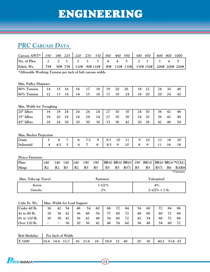
Carcass AWT* 150 180 225 220 270 330 360 440 550 300 450 600 800 1000
No. of Plies 2 2 3 2 3 3 4 4 5 2 3 3 4 5
Fabric Wt. 75# 90# 75# 110# 90# 110# 90# 110# 110# 150# 150# 200# 200# 200#
*Allowable Working Tension per inch of belt carcass width.
Min. Pulley Diameter
80% Tension 14 15 16 16 17 18 19 20 26 18 22 24 30 48
60% Tension 12 13 14 14 15 16 17 18 24 16 20 20 24 42
Min. Width for Troughing
20° Idlers 14 18 24 24 24 24 27 30 30 24 30 36 42 48
35° Idlers 18 20 24 24 24 24 27 30 36 24 30 36 42 48
45° Idlers 18 24 30 30 30 30 33 36 42 30 36 42 48 54
Max. Bucket Projection Grain 5 6 7 6 7.5 9 9.5 10 11 9 10 12 18 20 Industrial 4 4.5 5 6 7 8 8.5 9 10 8 9 11 16 18
Flexco Fasteners
Plate 140 140 140 140 190 190 BR10 BR10 BR10 190 BR10 BR10 BR14 *VulC.
Hinge R2 R2 R5 R2 R5 R5 R5 R5 R51⁄2 R5 R5 R51⁄2 R6 RAR8
*Vulcanize
Max. Take-up Travel Fasteners Vulcanized
Screw 1-1/2% 4% Gravity 2% 2-1/2% + 2 ft.
Cube Ft. Wt. Max. Width for load Support
under 40 lb. 36 42 54 48 54 60 66 72 84 54 60 72 84 96
41 to 80 lb. 30 36 42 36 48 54 57 60 72 48 60 60 72 84 81 to 120 lb. 30 36 42 36 42 48 54 60 72 42 54 60 72 84 Over 120 lb. - - 36 30 36 42 46 54 60 36 48 54 60 72
Belt Modulus Per Inch of Width
X 1000 10.4 14.4 15.7 16 21.6 24 28.8 32 40 20 30 40.2 53.6 67
PRC Carcass Data
Compound speCifiCations

65
- 400º HOT MATERIAL 1900 650 950 65 1.14 Chlorobutyl - PRC GRD I / GRX 3050 580 1500 64 1.14 Cut & Gouge Resistant - PRC GRD II / GTX 2400 640 1100 60 1.14 Premium Service SBR - 300º HIGH HEAT 2700 580 1300 63 1.14 High Temp. SBR
- “MOR” 2400 600 1100 62 1.15 Moderately Oil Resistant - GRD II / X-PORT 2050 400 1200 68 1.25 General Purpose SBR - HYFLEX / AR 3000 630 1300 65 1.14 High Flexibility & Abrasion - POLAR BEAR 2590 560 1300 63 1.14 Low Temp. -80 Deg.
- MSHA / AR 2100 525 1000 65 1.25 Abrasion Resistant-Mining - MSHA / MINE STAR 1400 450 500 60 1.54 Underground Coal - Part 14 - MSHA / NITRILE 2000 500 1100 65 1.35 Coal Prep & Grain - MSHA / CLIMATIC 1600 450 1150 70 1.37 Bulk Coal Handling - WASTE TREATMENT 2200 510 1100 62 1.16 Municipal Disposal - ALUMINA 3000 550 1300 65 1.17 Desiccation Resistant
- 350º HOT ASPHALT 1600 500 1150 62 1.25 Nitrile - PRC GRD II / PACIFIC 2400 640 1100 60 1.14 Premium Serice SBR
Compound speCifiCations
16
21
22
23
24
C2
29
31
32
34
35
36
37
38
61
95
Tensile Elongation Modulus Durometer Specific Compounds: (psi) (%) (300%) (hardness) Gravity
#
#
#
#
#
#
#
#
#
#
#
#
#
#
#
#
PRC stock #’s

66
New conveyor belt should be stored upright in the factory package until used, preferably on a dry surface. Block it safely so it can’t accidentally roll or tip over. Do not lay on its side or lean against a wall! Keep belting out of direct sunlight or where ozone is present as it will deteriorate exposed rubber over time. Belts should not be stored in excessively wet places or in areas where oils, acids, and other chemicals are present. Motor-control rooms, welding shops, and other places where ozone is generated should like -wise be avoided.
Excessive temperature variations should also be avoided and can have an adverse effect on a belt over time. Low temperatures or prolonged storage can harden or stiffen the compounds. If installed in this stiffened state, the belt may not train well until it adjusts or ‘’warms up’’ to the system.
During longer periods of storage, heavier rolls weighing more than 10,000 lbs. should be placed in an A-Frame or if left standing, rotated a quarter turn every three months to avoid ‘’flat spots’’ from its own weight.
Do Not Lay on End!
stoRage

67
stoRage
Factory packaging is designed to protect your conveyor belt during normal shipping and handling. When your belt arrives, be careful unloading it. Don’t drop or handle it roughly as this could break the packaging and cause the belt to telescope. Once ‘’scooped’’ it is nearly impossible to re-roll.
Do not roll the slab. If there is no other way to move the belt, then roll it in the direction the belt is wound. Rolling in the opposite direction can cause it to loosen and telescope.
The optimum way to move a belt is to slip a sturdy hoisting bar through the center core. Then, lift the belt with a spreader bar with chains or strong cables. Protect the belt edges against rubbing by using a spreader bar that is wide enough or with wood planks / old belting next to chains or cables.
handling
SpreaderBar
Core Bar

68
Mount roll of belting on a suitable core bar for unrolling and threading on to the conveyor system. Conveyor belting is normally rolled at the factory with the carrying side out. Consequently, when mounting the roll the belt must lead off the top of the roll if it is being pulled onto the troughing idlers but off the bottom of the roll if it is being pulled on to the return side.
In certain cases, where head room does not permit maneuvering of a roll, the belt may have to be pulled off the roll and ‘’reefed’’. Extreme care should be exercised to see that the loops have large bends to avoid kinking or undue strain on the belt, and no weight should ever be placed on the belt when in this position or the belt can be lain on a turn table with a vertical spindle. The belt will make a 90º twist as it is spun off. In this procedure, care must be exercised to avoid excessive abrasion to the belt edges.
No Weight ToBe Placed On Top
Belt Reefing
installation
No Weight ToBe Placed On Top
Keep Bends Large ToPrevent Breaking Carcass
tRaining
Spindle Method

69
installation
Training of a conveyor belt is the process of adjusting idlers, pulleys, and loading conditions in a manner which will correct any tendency of the belt to run other than centrally. Once installed on the conveyor, problems of design, manufacture, erection, and other abnormalities become apparent. All too often these conditions are considered ‘’belt problems’’.
If designed, manufactured, slit and cut properly, the belt will ‘’go where directed’’ by the conveyor system as designed and built. The conveyor belt serves as an indicator and should be so regarded. Rarely is a belt at fault and is more likely reacting to a structural defect or maladjustment to the system. alleviates this condition since all products are made to width, not slit from a slab where ‘’camber’’ can occur.
When all portions of a belt run off through a part of the conveyor length, the cause is probably in the alignment or leveling of the conveyor structure, idlers, or pulleys in that area. If one or more portions of the belt run off at all points along the conveyor, the cause is more likely the belt itself, in the splice or in the loading of the belt. When loaded off-center, the center of gravity of the load tends to find the center of the troughing idlers, thus leading the belt off its lightly loaded edge.
It is Important to Realize That Belt Tracking is a System Problem & Should be Approached From a Systems Point of View!
tRaining
Effects of Off- Center Loading!
Spill
Edge Wear

70
The Basic Primary Rule When Tracking a Conveyor Belt is Simple:
The Belt Moves Toward That End of The Roll / Idler it Contacts First!
Initial installation of conveyor equipment should ensure proper alignment of all pulleys, troughing and return idlers, i.e., and should be placed at right angles to the direction of belt travel, leveled and centered on a straight line.
The best procedure in starting the training sequence is to start with the return run and work toward the tail pulley:
1 Move from idler to idler in direction of belt travel.
2 Shift only one idler at a time. Shifting subsequent idlers may cause over correction.
3 Make slight adjustments rather than extreme ones.
4 Wait for at least 2 or 3 revolutions before making further adjustments.
5 Try never to adjust pulleys for belt training.
6 Apply the ‘’Handle Bar’’ method to each of these indicators. This will help ensure early centering of the belt on the tail pulley so that it can be centrally loaded.
If the empty belt troughs readily, not erratic, training should be complete. Should the belt tend toward stiffness and erratic running, place some load onto the belt. The added weight will help control the belt and aid during ‘’Break-In’’.
1
2
3
4
5
6
Correct Troughing
tRaining sequenCe loading
Transverse Stiffness

71
tRaining sequenCe
Receiving material off center will cause the belt to move sideways after loading as the center of the load seeks the lowest point in the troughing idlers. This can be corrected by proper chute arrangement provided, of course, that the belt is centered as it enters the loading point. The loading point of any conveyor is nearly always the critical point, the life determining point of the belt. Here the conveyor receives its major abrasion, and practically all of its impact. The ‘’ideal condition’’ is to have the material pass from chute to belt at the same speed and direction of travel as the belt with a minimum amount of impact.
The width of the receiving end of the loading chute should be great enough to accept material lying on the extreme edge of the preceding belt or feeder, and its position determined by the trajectory of the material coming into it. At no place should the chute be less than twice the size of the largest lumps, if fines are present, and 3-1/2 times the size of lumps, if uniform. The discharge width of the chute thus determined should not exceed about 2/3 of the receiving belts width.
loading
Rubber Lip
2/3 widthof receivingbelt
Rubber Lip
Belt WiperDribble Chute Recelving
belt
Tail pulleyof receiving belt
Head pulleyof dischargebelt
Simple Conveyor Loading Points

72
The slope of the chute is determined by the nature of the material, its entering velocity and length of the chute. This value varies with each particular installation, but about 35 degrees has been found satisfactory for most dry industrial materials such as rock and coal. An attempt to approach the above ‘’ideal condition’’ should be made continually by adjusting the chute arrangement. Optimum loading and transferring through chutes still requires considerable experimental adjustment in the field.
Skirt boards should be used to further center and settle the load as it leaves the loading point. The steel structure of the chute and skirts never should be placed closer to the surface of the belt than 1''. This distance to be made increasing in the direction of belt travel to free any material trapped between the belt surface and the skirt. Skirt boards are usually 4 or 5 times the belt width in length, but may vary considerably due to belt speed, type of material and lump size.
BA C
1'' Minimum Increasing in direction of travel
Usually4 to 5 x Belt
Width
Variable Variable Variable Idler Idler Idler Angle Angle Angle
Skirtboardrubber heldin compression
Skirtboardrubber heldin compression
Skirtboardrubber Backup Plate
Backup PlateBackup Plate
loading load suppoRt
Sample Skirtboard Arrangements

73
loading load suppoRt
20º
Most conveyor belts carrying ‘’free flowing’’ materials operate over troughed idlers. The troughing angle of these idlers will usually vary from 20 to 45 degrees... and beyond. The trough-angle affects the belt by creating a line along which the belt is constantly flexed. The greater the trough angle, the greater the flexing action. When the belt is fully loaded, the portion of the load (X) directly over the idler junction gap forces the belt to flex to a shorter radius. The heavier the load, the smaller the radius through which the belt must flex. Further, at higher troughing angles (like 45 degrees), gravitational force is exerted on the portion of the belt in contact with the wing idler. All these forces are trying to pull that belt down into that idler junction gap. Consequently, consideration must be given to designing the belt with sufficient transverse rigidity and flex life so that for a given idler angle and load weight, premature belt failure will not occur. This is done by designing the belt with sufficient transverse stiffness to ‘’bridge’’ the idler junction gap with a satisfactory radius.
This specification is detailed in the ‘’load support’’ engineering section, page . The load support number refers to the maximum width possible for a given belt construction at a given troughing angle carrying material of a specific density.
Single-plied belt constructions do well on idler sets up to and including 35 degrees. Plied constructions are generally thicker for a given belt tension rating, and therefore, appear to perform better on 45 degree troughing idler sets.
Differential in Radius Between Idlers Proper Bridging of Idler Junction
45º
64
Improper Bridging of Idler Junction

74
tRansition
1 3
4
5
2
3
Belt Width x 3 x 4 x 5
20º35º
45º
20º45º
35ºTroughing Idlers
Belt Edge
Tangent to
Top of Pulley
Trough
Transition for 100% AWT with Belt Centered on Tangent
20-27 degree troughing systems - - - times belt width.
35 degree troughing systems - - - - - times belt width.
45 degree troughing systems - - - - - times belt width.
Transition distance is defined as the distance from the center line of the first fully troughed idler system to the center line of either the head or tail pulley. The geometry of the situation, causes the edge of the belt to be stretched since it is following the hypotenuse of a right triangle. The distance from the pulley to the top of the wing roll is greater than the distance from the pulley to the center roll of the troughing set. If the transition distance is too short, the edge of the belt can be over-stretched. This will adversely affect the load support and belt life. A good rule of thumb regarding transition distance is:
The Transition Distances Shown Will Accommodate Virtually all Belt Constructions, Including Cable Belts. Most Belts, Properly Installed, Will Give Many Years of . . . Trouble – Free Service!
distanCes

75
45º35º 20º
If a particular conveyor system has shorter transition distances than those above, there are modifications to the system that can help reduce the stress on the belt:
Elevate the terminal pulley in the system relative to its height verses the center roll of the troughing idlers in the system.
Remove first high angle idler in the transition area and use a variable angle troughing idler, ‘’adjust’’ it to support the belt without added stress.
A
B
distanCes
This differential in distance creates higher tensions in the edge of the belt than the center of the belt, which can create belt problems.
The most common of these problems are:
If transition is too short at the head pulley: Idler junction gap failure. Splice failure (from the outside in). Belt folding up in the center and folding over on itself. If transition is too short at the tail pulley: Splice failure (from the center out). Premature wear or failure in the center of the belt.
Transition Distance

76
The smallest pulley diameter the belt will encounter in the conveyor system is a primary consideration in selecting the proper conveyor belt. When a belt travels around a pulley, the outer plies of the carcass traverse a greater distance than the inner plies. It is important that as the belt wraps around that pulley, under tension, the stress in the belt is below the fatigue limit of the bond between the belt components. Over stressing the belt, particularly the bond between the individual plies and the skim, can result in ply separation and premature belt failure... especially, at the belt splices. In some applications, due to system limitations, smaller than recommended pulleys may be used. This will affect the service life of the belt and will result in more frequent splice replacements. A given belt construction has a characteristic “flexibility” in the lengthwise direction.
In most applications where a mechanical fastener is used to splice the belt, the minimum recommended pulley diameter for the fastener will be the limiting factor. This by virtue of the fact that rubber and fabric is more flexible than metal. Also, it should be noted that if a conveyor system utilizes a wing type terminal pulley, that pulley should be 25% greater in diameter than the minimum pulley diameter normally recommended.
Buckling of Conveyor Belt by Bending
Top Cover 4 Plies Fabric
Bottom Cover
PulleySurface
pulley diameteR squaRing

77
pulley diameteR squaRing
Accurate squaring of the belt ends prior to lacing is essential to correct belt tracking and helps distribute stress evenly throughout the joint. It is important to note that belt ends are not necessarily square when they are shipped. Further, the width-wise fabric wales are not necessarily square to the belt’s longitudinal axis. These cannot be used as guides to cut the belt ends.
To Properly Square the Belt Ends, Use the Center Line Method!
To establish the belt center line, start near the belt end as shown. Measure the belt width at five points approximately 10'' apart. Divide each measurement in two and mark the center points.
Using these five ‘’center points’’ draw the resultant ‘’average’’ center line. Next, using a carpenter square or ‘’T’’ square, draw a ‘’cut line’’ across the width of the belt near the belt end as shown. It is also a good idea to mark several right angle reference lines across the belt surface for use as guidelines later on.
Using the ‘’cut line’’ as the guide, cut off the end of the belt with a razor knife. Make sure that the cut is clean and vertical. This operation should then be repeated on the other end of the belt. *Keep in mind that the final belt length may need to include an allowance for such things as diagonal splice, skive taper length, skive overlap, fastener extension, etc. . . . depending upon what kind of splice is being performed.
Belt Center line.
Marking ofCut-Line and Other Right Angle Guide Lines.
‘’T’’ Square
End
Cut line
End

78
Fast & Simple Installation! The speed and simplicity of mechanical splice installation represent major advantages over thevulcanization process. Depending on belt width and thickness, most mechanical splices can be finishedin less than one hour.
Compare that to vulcanized splices. Installation can take from four to six hours, and also require idealtemperature & humidity conditions. Also, worn belts and many older belts won’t accept a vulcanizedsplice, making mechanical fasteners the only alternative. And of course, timely installation often depends on the availability of a qualified vulcanizing contractor.
Only Standard Tools Required! Mechanical splice installation is simple when compared to vulcanization. Maintenance crews can finishthe job using only simple instructions and portable application tools, such as hammers, punches, wrenches,or lacers.
Hot vulcanization, on the other hand, requires large and heavy heating presses. What’s more, specialhand tool are required to split the belt plies and prepare the belt surface. Newer belt synthetics must alsobe carefully matched with vulcanizing solvents, cements, & compounds. These substance are highly toxic, have limited shelf life and can be hazardous to both health and the environment, so installers mustpossess a thorough knowledge of vulcanizing materials and adhesives.
Easy Inspection! Because a mechanical splice is visible, any wear or deterioration is immediately apparent. Replacementor repairs can be scheduled during brief periods of downtime or at the end of a shift. A deterioratingvulcanized splice, in comparison, is not easily detected. Catastrophic line failure can be the firstindication of trouble once adhesion breakdown occurs inside a vulcanized splice.
Maintenance crews using simple, everyday tools can install a Splice on-site in a fraction of the time required for vulcanization.
In addition to special heat presses, vulcanization is also a time -consuming & expensive process.
Mechanical fasteners & vulcanizing are the most common forms of ‘’joining’’ belts endless in the field. While each has its place with certain advantages, it is best to familiarize yourself with the intended service work for optimal performance and to guard against under / overkill applications. If unsure of such a deci-sion, contact the Factory for best recommendation and guidanse: 1•800•633•1470.
fasteneRs vs. vulCanizing

79
fasteneRs vs. vulCanizing
On a properly engineered, well maintained conveyor system, a vulcanized splice performed correctly should last for many years and in some cases last the life of the belt. Utilizing and understanding these Best Practices in conveyor belt splicing is the best way to assure the success and performance of your splice.
1. Process Control of Vulcanizing Temperature Time, & Pressure is Critical. Thermocouples provide precise temperature monitoring at the platen-belt interface. Thermostats on many vulcanizers do not indicate the actual temperature. Without precise monitoring, the temperature can fluctuate drastically, resulting in a splice that is either ‘’over or under cured’’. Either condition will limit the life of the splice. Top splicers will use such thermocouples to monitor and gather cure temperature data. A record of this data can then be supplied to to assure that the curing process was performed properly.
Use Proper Knives & Skiving Tecniques to Avoid Nicking of Fabric Plies.
Nicking the adjacent fabric plies with a knife effectively reduces the tension rating of the belt carcass because the tension members (warp cords) are disabled if they are cut or nicked. Use quality tools such as single-ply knives designed specially for this procedure.
Perform Minimal Buffing of the Exposed Fabric Plies. The fabric plies of all belts are coated with RFL (resorcinol-formaldehyde-latex) or other special coatings to enhance the adhesion of the rubber to the fabric. These dip coats should not be buffed off when preparing the belt splice or reduced ply and cover adhesion will result. If residual rubber must be buffed off after stripping down the step, it must be done carefully so that the buffer wheel does not actually touch the fabric. Severe over buffing will reduce belt strength and integrity by damaging both the warp and fill cords. Buffer wheel should not exceed 2000 RPM.
1
2
3
PRC Best Practices
vulCanizing

80
vulCanizing
When a belt splice is assembled and cured before the cement has had sufficient time to dry, the heat from the vulcanizer will cause the solvents and carriers in the cement to vaporize and form bubbles. If the surface area of these ‘’ply or cover blows’’ is large enough, the strength of the splice is severely limited. Ply separations can also occur when cements and solvents are not allowed to come up to room temperature after removal from cold storage because of water condensation occurs on cold surfaces. Additionally, try not to accelerate the drying process by using heat guns or hair dryers that can cause a ‘’skin’’ to form on the surface of still wet cements. Space heaters can be used to accelerate the drying time provided safety is not compromised in any way.
Use the right tools and methods to assure that the fabric plies are not damaged when they are lifted. Prodding tools should have smooth, rounded corners. Do not use screwdrivers!
When step lengths are shortened by more than an inch or two to accommodate vulcanizers that are not large enough for the job, splice strength and integrity is severely reduced. It is recommended to cure the splice in one heat, but if the vulcanizer is too short to cure the splice then multiple heats can be used as long as the fill-in strips are completely cured in a single heat. See pages 82-83 for splice dimensions / recommended cure rates or contact Technical Support for further information &
Experience has shown that almost anything can end up inside a vulcanized splice from sand, rocks, trash, even work gloves left on the inside of failed splices. For these reasons, the splicing work area must be clean and protected. Tents, awnings, traps, or temporary plywood walls and ceilings should be used depending on the particular circumstances or where conditions allow. These added measures will help avoid contamination in the splice.
4
5
6
7
guidelines:1•800•633•1470.
Allow Cements to Dry Completely Before Assembling & Curing the Splice.
Avoid Over prodding the Fabric When Lifting the Plies.
Use Specified Step & Finger Lengths.
Work Clean to Help Assure a Clean Assembly.

81
vulCanizing
NEVER USE CEMENTS OR TIE GUMS THAT ARE OUT OF DATE. Universal Splice Materials are manufactured to the highest standards. Part of this quality control comes from our custom mixing plant in Guntersville Alabama. There, materials are produced and recorded by date, and then refrigerated to ensure maximum freshness and longevity. Splice materials should never be stored in sunlight, hot -humid conditions or left in a prolonged state at room temperature. When unused materials reach life limits, dispose of properly in accordance with federal, state, and local ordinances. USE CORRECTLY SPECIFIED GUMS & CEMENTS. For best adhesions and splice longevity, conveyor belts should be spliced with our Universal Splice Materials. The same compounds and stocks used in the production of our belt lines are supplied to our customers to assure complete compatibility and highest performance. Even with our materials, care must be observed to ensure that the correct gums and cements are used. For com plete cross reference/splice recommendations, please refer to page or call Technical Support: 1•800•633•1470.
ALIGN THE SPLICE SqUARELY AND PROPERLY.
Splices that are not aligned cause many problems! Tracking and training problems can frequently be traced back to splices that are not square. Additionally, splices that are out of square do not distribute the tension load evenly across the splice, which can cause premature splice and belt failure.
8
9
10
Never Use Cements or Tie Gums That Are Out of Date.
Use Correctly Specified Gums & Cements.
Align the Splice Squarely & Properly.
25

82
step lengths
When the in conveyor belt splicing previously referenced are incorporated into your S.O.P. and the system is properly engineered and well-maintained, a dependable, long splice life can be achieved.
Plied Belting Vulcanized Splice Dimensions
Step Fill-In Overall Splice Outer’’
Belt No. of Length Length Length (in) Ply Joint
Style Plies (Inches) (Inches) w/o bias angle Type 2-180 2 6 4 10 Butt 2-220 2 8 4 12 Butt 2-250 2 10 4 14 Butt 2-400 2 15 4 19 Butt 2-500 2 18 4 22 Butt 2-600 2 20 4 24 Butt 3-330 3 8 4 20 Butt 3-375 3 10 4 24 Butt 3-450 3 12 4 28 Butt 3-600 3 15 4 34 Butt 3-750 3 18 4 40 Butt 3-900 3 20 4 44 Butt 4-440 4 8 4 28 Butt 4-500 4 10 4 34 Butt 4-600 4 12 4 40 Butt 4-800 4 15 4 49 Butt 4-1000 4 18 4 58 Butt 4-1200 4 20 4 64 Butt 5-550 5 8 4 36 Butt 5-750 5 12 4 52 Butt 5-1000 5 15 4 64 Butt 5-1250 5 18 4 76 Butt 5-1500 5 20 4 84 Butt
Best Practices
CuRe Rates
’’

83
step lengths CuRe Rates
Because most conveyor belt splicing is done on the job, portable, electrically-heated, vulcanizers are used. Curing time depends on belt thickness, rubber compound, and type of vulcanizer being used. The following chart of curing times can be used for either splice or repair work:
Curing Time for Conveyor Belting
GRADE I & II NITRIlE OR NEOPRENE BuTYl (EPDM) (IN MINUTES AT 287 deg. f) (IN MINUTES AT 287 deg. f) (IN MINUTES AT 287 deg. f)
Thickness of Belt 1 Heated 2 Heated 1 Heated 2 Heated 2 Heated or Repair Depth Platen Platens Platen Platens Platens 3/16'' and less 34 23 50 37 45 1/4'' 38 24 52 37 46 5/16'' 42 26 53 40 47 3/8'' – 26 – 42 48 7/16'' Use 2- 27 Use 2- 43 48 1/2'' platen 28 platen 45 49 9/16'' press 29 press 47 50 5/8'' above 30 above 48 51 11/16'' 5/16'' 31 5/16'' 49 52 3/4'' – 32 – 50 52
Over 3/4'': Add 2 minutes for each 1/16'' of additional thickness. *This curing schedule is intended for portable
vulcanizers under average field conditions. For Belt Repair Shops having permanent repair presses in heated
buildings, the time can be reduced 5 minutes from the schedule shown for Natural or SBR.
Generally, vulcanizers are heated to 287 degrees F. After vulcanizer is clamped on the belt, platen temperature will drop. Let it return to 287 degrees before initiating recommended cure cycle. The curing temperature (287 F.) must be maintained throughout time of vulcanization. If it drops, allow more curing time; if it rises, a shorter time will do:
Curing Time for Belt Joint
Thickness of Belt Vulcanizer with Vulcanizer with Vulcanizer with Vulcanizer with
2 Heated Platens 1 Heated Platen 2 Heated Platens 1 Heated Platen 3/16'' and under 18 24 37 50 1/4'' 19 26 39 52 5/16'' 20 28 40 53 3/8'' 21 31 42 57 7/16'' 22 31 43 57 1/2'' 24 31 45 57 9/16'' 26 31 47 57 5/8'' 27 31 48 57 11/16'' 28 31 49 57 3/4'' 29 31 50 57
SBR / NATuRAl RuBBER OIl PROOF length of Heat - Minutes

84
side irons / timing
Use side irons on each edge of belt, full length of the vulcanizer to prevent the platens from “bowing” under pressure, and to contain the flow. Irons should extend outside of the vulcanizer and clamped across the width of the belt to hold the irons during cure. *Do not start timing the cure until the vulcanizer reaches recommended temperature. Always start with a cold press.
Overlapping Heats
When vulcanizer platens will not cover entire splice, two or more heats or “cures” are necessary. Multiple cures should overlap preceding heat by 2 to 4 inches. The vulcanizer should cover the full uncured splice plus a minimum overlap of 2'' into the Factory cured belt ends. A common practice is to cure top cover fill-in first. Then proceed in overlapping steps toward bottom cover fill-in.
Cooling Splice
Rubber compounds lose tensile strength at temperatures used during vulcanizing. Therefore, allow belt splice to cool to normal air temperature before maximum belt tension is applied. This is important when operating tensions are 80 to 100 percent of maximum permissible tensions.
Under curing / Over curing
Under cured rubber is soft and lacks resilience. To test: Press end of prodding tool into rubber. If indentation remains, rubber is probably under cured and additional time in vulcanizer is needed. Over curing, up to a degree, is indicated by too much hardness as compared with rest of belt rubber. Extreme over curing can cause softening (known as reversion) which becomes worse if further curing is attempted.
Blow-Ups / Blisters
A blow-up or blister that appears when platens are removed is caused by moisture in the belt or by trapped air in new material. Moisture may be water that was in the belt carcass, or in the solvents being used in cleaning off skim coat rubber. To prevent blow-ups, allow vulcanizer platens to cool below steam temperature (212 degrees at sea level) before releasing platen pressure. If a blow-up or blister does occur, repair work must be done in affected area. Simply reapplying vulcanizing heat and pressure will not remedy the condition as cement and tie gum already have been fully ‘’cooked’’ and further curing will not cause them to adhere.
CuRing tips

85
Conveyor runs to one side at given point on structure. Particular section of belt runs to one side at all points on conveyor.
Belt runs to one side for long distance or entire length of conveyor.
Belt runs off at tail pulley.
Belt runs off at head pulley.
Belt slip.
Belt slip on starting.
Excessive belt stretch.
Grooving, gouging or stripping of top cover.
Excessive top cover wear, uniform around belt.
Severe pulley cover wear.
Longitudinal grooving or cracking of bottom cover.
Covers harden or crack.
Cover swells in spots or streaks.
Belt breaks at or behind fasteners; fasteners pull out.
Vulcanized splice separation.
Excessive edge wear, broken edges.
Transverse breaks at belt edge.
Short breaks in carcass parallel to belt edge, star breaks in carcass.
Ply separation.
Carcass fatigue at idler junction.
Cover blisters or sand blisters.
Belt cupping- new belt.
Belt cupping - old belt (was OK when new).
CuRing tips
tRouble shooting
5 4
6 7
23 37
16 17
45 21
21 23
46
21
1
39 10 1
34 31 33
18 25 26
29 30 23
2
33 10 1 3
13 14 15 16
4 10 9 33
24 22 12 23
8 10 40 7
3
34 33 31 10 4
19 20 10 8 36
38 30 12 17 25
44
39 8 5 1 2 3
41 42 43 12 32 35
4 9 10 17 11 27
25 26 27 28 29 36
Problem: Cause: in order of probable occurrence.

86
Idlers or pulleys out-of-square with center line of belt: readjust idlers in affected area.
Conveyor frame or structure crooked: straighten in affected area.
Idler stands not centered on belt: readjust idlers in affected area.
Sticking idlers: free idlers and improve maintenance and lubrication.
Buildup of material on idlers: remove accumulation; improve maintenance, install scraper or other
cleaning devices. Belt not joined squarely: remove affected splice and resplice.
Bowed belt: for new belt this condition should disappear during break-in; in rare instances belt must
be straightened or replaced; check storage and handling of belt rolls.
Off-center loading or poor loading: adjust chute to place load on center of belt; discharge material in direction of belt travel at or near belt speed. Slippage on drive pulley: increase tension thru screw take up or add counterweight; lag drive pulley; increase arc of contact. Material spillage and buildup: improve loading and transfer conditions; install cleaning devices; improve maintenance. Bolt heads protruding above lagging: tighten bolts; replace lagging; use vulcanized-on lagging. Tension too high: increase speed, same tonnage; reduce tonnage, same speed; reduce friction with better maintenance and replacement of damaged idlers; decrease tension by increasing arc of contact or go to lagged pulley; reduce Counterweight to minimum amount.
Skirt boards improperly adjusted or of wrong material: adjust skirt board supports to minimum 1’’ between metal and belt with gap increasing in direction of belt travel; use skirt board rubber (Not Old Belt)! Belt spanking down under load impact: install cushion idlers.
Material hanging up in or under chute: improve loading to reduce spillage; install baffles; widen
chute.
Impact of material on belt: reduce impact by improving chute design; install impact idlers.
Material trapped between belt and pulley: install plows or scrapers on return run ahead of tail pulley.
Belt edges folding up on structure: same corrections as for 1, 2, 3; install limit switches; provide
more clearance.
Dirty, stuck, or misaligned return rolls: remove accumulations; install cleaning devices, use self-cleaning return rolls, improve maintenance and lubrication. Cover quality too low: replace with belt of heavier cover gauge or higher quality rubber.
Spilled oil or grease, over-lubrication of idlers: improve housekeeping; reduce quantity of grease
used; check grease seals.
Wrong type of fastener, fastener too tight or too loose: use proper fastener and splice technique; set up schedule for regular fastener inspection.
22
21
20
19
18
17
16
15
14
13
12
11
10
9
8
7
6
5
4
3
2
1
tRouble shooting tRouble shooting

87
tRouble shooting
Fastener plates too long for pulley size: replace with smaller fastener; increase pulley size.
Improper transition between troughed belt and terminal pulleys: adjust transition in accordance
with engineering, pages 74-75 .
Severe convex (hump) vertical curve: decrease idler spacing in curve; increase curve radius.
Excessive forward tilt of trough rolls: reduce forward tilt of idlers to no more than 2 degrees from
vertical.
Excess gap between idler rolls: replace idlers; replace with heavier belt.
Insufficient transverse stiffness: replace with the proper belt.
Pulleys too small: use larger diameter pulleys.
Counterweight too light: add counterweight or increase screw take-up tension to value determined
from calculations.
Counterweight too heavy: lighten counterweight to value required by calculations.
Pulley lagging worn: replace pulley lagging.
Insufficient traction between belt and pulley: lag drive pulley; increase belt wrap; install belt
cleaning devices.
System under belted: recalculate belt tensions and select proper belt.
36. Excessive sag between idlers causing load to work and shuffle on belt as it passes over idlers:
increase tension if unnecessarily low; reduce idler spacing.
Improper storage or handling: refer to pages 66-67 for proper storage and handling instructions.
Belt improperly spliced: re splice using proper method as recommended by .
Belt running off-center around the tail pulley and through the loading area: install training idlers
on the return run prior to tail pulley.
Belt hitting structure: install training idlers on carrying and return run.
Improper belt installation causing apparent excessive belt stretch: pull belt through counterweight
with a tension equal to at least empty running tension; run belt in with mechanical fasteners.
Improper initial positioning of counterweight in its carriage causing apparent excessive belt stretch:
contact for recommended initial position.
Insufficient counterweight travel: contact for recommended minimum distances.
Structure not level: level structure in affected area.
Cover cuts or very small cover away from carcass: make spot repair with vulcanizer or self-curing
repair material.
Excessive cover gauge ratio: use a belt with a lower gauge ratio and/or a thicker carcass. 46
45
44
43
42
41
40
39
38
37
36
35
34
33
32
31
30
29
28
27
26
25
24
23 Heat or chemical damage: use belt designed for specific condition.
tRouble shooting

88
ConveyoR CalCulation
Customer Date:
Conveyor location Conveyor #
Belt Width Conveyor length (c:c) lift
Belt Speed (Ft / Min) Material Conveyed
Material Size Shape Fall
Material Wt. (lbs / Cu Ft.) Desired Tons / Hr
Troughing Idlers (Deg) Take up location
Weight of Gravity Take up Pulley Sizes
Drive Pulley (lagged or Plain) Degree of Wrap
Motor HP Type of Motor
Calculated Belt Carcass Tension (PIW)
Calculated Total Belt Tension
Suggested Belt Carcass
Suggested Belt Compound Covers
Maximum Horsepower Will Deliver Tons / Hr
Servicing Distributor
location By
Often times, a simple calculation can save a Heap of Trouble when a belt does not perform as intended. For conveyor engineering support, fill in the top portion with as much detail as possible & Fax or Email to the Factory for immediate assistance: 334•271•3194 / [email protected]
CalCulation notes
prc “patriot” belt modeling system

89
ConveyoR CalCulation CalCulation notes
prc “patriot” belt modeling system

90
WARRANTY
All merchandise is guaranteed against material defect and workmanship for the life of the product. Any product found to be faulty by our laboratory will be replaced or credited, our choice on a prorate basis. Claims must be addressed to the General Manager of the plant where produced, and a Returned Goods Authorization (RGA) must be used in prepaying all merchandise claims to the factory. Freight will be refunded if claim is allowed. usually, examination in the field by a factory representative, with a sample to the laboratory, is sufficient to settle any differences. Call the factory concerned for prompt attention.
Montgomery, Alabama USA1•800•633•1470 • Fax: 334•271•3194
www.pricerubber.com
US Pat. # 4,477,202
US Pat. # 4,477,202US Pat. #
4,015,791 US Pat. # 4,666,100
US Pat. # 4,543,140
US Pat. #
7,703,600
US Pat. #
4,484,373
With over U.S. Patents through advanced technological research & product innovation, continues to serve as an industry leader providing World Class goods and services to you, our valued customer!
patents & waRRanty
13