
Engineering Fracture Mechanics - National Taiwan Ocean...
15
Elastic notch stress intensity factors for sharply V-notched rounded bars under torsion M. Zappalorto, P. Lazzarin * , F. Berto Department of Management and Engineering, University of Padova, Stradella San Nicola 3, 36100 Vicenza, Italy article info Article history: Received 18 July 2008 Received in revised form 4 November 2008 Accepted 26 November 2008 Available online 3 December 2008 Keywords: Elastic stress distributions Notch stress intensity factors (NSIFs) Torsion abstract The paper deals with the determination of analytical expressions for the mode III notch stress intensity factors for circumferentially-sharply-notched rounded bars under torsion loading, starting from the theoretical stress concentration factors of the corresponding notch problem. An exact, closed-form solution for the NSIFs is obtained for deep notches; subsequently the solution is extended also to finite notched components taking advantage of a shape function determined by a numerical best fitting procedure. Ó 2008 Elsevier Ltd. All rights reserved. 1. Introduction While the linear elastic stress fields in the vicinity of the crack tip were first determined by Westergaard [1], the asymp- totic nature of the stress fields due to pointed V-notches was first documented by Williams [2] who demonstrated that the degree of singularity of mode I and mode II stress distributions depends on the V-notch angle. The intensity of the stress field was later given in terms of notch (or generalised) stress intensity factors, NSIFs, by Gross and Mendelson [3] who also pro- vided a set of NSIFs from V-notches in plates. Subsequently the stress distributions due to sharp V-notches under antiplane shear were given by Seweryn and Molski [4], Dunn et al. [5], and Qian and Hasebe [6]. In the context of a stress field theory, the NSIFs were applied to the fracture toughness of components made of brittle materials (see among the others, Nui et al. [7], Dunn et al. [8,9], Gomez and Elices [10,11]) as well as for fatigue crack ini- tiation assessments at notches and weld toes (Boukharouba et al. [12], Verreman and Nie [13]). Gomez and Elices [11] were able to demonstrate that a single non-dimensional curve provides an accurate fit of experimental data from static tests car- ried out on V-notched specimens of steel, aluminum, PMMA and PVC. Their master curve plots as a function of the notch angle a non-dimensional parameter which combines together the critical value of the NSIF, the fracture toughness K IC and a characteristic length of the material L ch . Good agreement between computed and measured failure loads were ob- tained by Gomez and Elices not only for ideally sharp notches and brittle fracture, but also when root radii were small (typ- ically less than 0.05 mm) and when plasticity was contained. Dealing with fatigue problems it was noted by Verreman and Nie [13] that for engineering applications it is too complex to take into account the non-LEFM behaviour of a short crack and the multiple crack interaction on different planes influenced by loading parameters and statistical variations related to the irregularity of the toe profile. In these works it was assumed that a crack propagates from the notch tip when the actual value of the NSIF reaches a critical value. Under favourable circumstances, not only the fatigue crack initiation life but also the total fatigue life can be controlled by the NSIFs (Lazzarin and Tovo [14], Atzori et al. [15], Lazzarin and Livieri [16]). This occurs 0013-7944/$ - see front matter Ó 2008 Elsevier Ltd. All rights reserved. doi:10.1016/j.engfracmech.2008.11.008 * Corresponding author. E-mail address: [email protected] (P. Lazzarin). Engineering Fracture Mechanics 76 (2009) 439–453 Contents lists available at ScienceDirect Engineering Fracture Mechanics journal homepage: www.elsevier.com/locate/engfracmech
Transcript of Engineering Fracture Mechanics - National Taiwan Ocean...
Engineering Fracture Mechanics 76 (2009) 439–453
Contents lists available at ScienceDirect
Engineering Fracture Mechanics
journal homepage: www.elsevier .com/locate /engfracmech
Elastic notch stress intensity factors for sharply V-notched roundedbars under torsion
M. Zappalorto, P. Lazzarin *, F. BertoDepartment of Management and Engineering, University of Padova, Stradella San Nicola 3, 36100 Vicenza, Italy
a r t i c l e i n f o
Article history:Received 18 July 2008Received in revised form 4 November 2008Accepted 26 November 2008Available online 3 December 2008
Keywords:Elastic stress distributionsNotch stress intensity factors (NSIFs)Torsion
0013-7944/$ - see front matter � 2008 Elsevier Ltddoi:10.1016/j.engfracmech.2008.11.008
* Corresponding author.E-mail address: [email protected] (P. Lazza
a b s t r a c t
The paper deals with the determination of analytical expressions for the mode III notchstress intensity factors for circumferentially-sharply-notched rounded bars under torsionloading, starting from the theoretical stress concentration factors of the correspondingnotch problem.
An exact, closed-form solution for the NSIFs is obtained for deep notches; subsequentlythe solution is extended also to finite notched components taking advantage of a shapefunction determined by a numerical best fitting procedure.
� 2008 Elsevier Ltd. All rights reserved.
1. Introduction
While the linear elastic stress fields in the vicinity of the crack tip were first determined by Westergaard [1], the asymp-totic nature of the stress fields due to pointed V-notches was first documented by Williams [2] who demonstrated that thedegree of singularity of mode I and mode II stress distributions depends on the V-notch angle. The intensity of the stress fieldwas later given in terms of notch (or generalised) stress intensity factors, NSIFs, by Gross and Mendelson [3] who also pro-vided a set of NSIFs from V-notches in plates. Subsequently the stress distributions due to sharp V-notches under antiplaneshear were given by Seweryn and Molski [4], Dunn et al. [5], and Qian and Hasebe [6].
In the context of a stress field theory, the NSIFs were applied to the fracture toughness of components made of brittlematerials (see among the others, Nui et al. [7], Dunn et al. [8,9], Gomez and Elices [10,11]) as well as for fatigue crack ini-tiation assessments at notches and weld toes (Boukharouba et al. [12], Verreman and Nie [13]). Gomez and Elices [11] wereable to demonstrate that a single non-dimensional curve provides an accurate fit of experimental data from static tests car-ried out on V-notched specimens of steel, aluminum, PMMA and PVC. Their master curve plots as a function of the notchangle a non-dimensional parameter which combines together the critical value of the NSIF, the fracture toughness KIC
and a characteristic length of the material Lch. Good agreement between computed and measured failure loads were ob-tained by Gomez and Elices not only for ideally sharp notches and brittle fracture, but also when root radii were small (typ-ically less than 0.05 mm) and when plasticity was contained. Dealing with fatigue problems it was noted by Verreman andNie [13] that for engineering applications it is too complex to take into account the non-LEFM behaviour of a short crack andthe multiple crack interaction on different planes influenced by loading parameters and statistical variations related to theirregularity of the toe profile. In these works it was assumed that a crack propagates from the notch tip when the actual valueof the NSIF reaches a critical value. Under favourable circumstances, not only the fatigue crack initiation life but also the totalfatigue life can be controlled by the NSIFs (Lazzarin and Tovo [14], Atzori et al. [15], Lazzarin and Livieri [16]). This occurs
. All rights reserved.
rin).
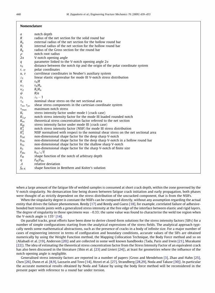
Nomenclature
a notch depthR radius of the net section for the solid round barRn external radius of the net section for the hollow round barRi internal radius of the net section for the hollow round barRg radius of the Gross section for the round barq notch root radius2a V-notch opening angleq parameter linked to the V-notch opening angle 2ar0 distance between the notch tip and the origin of the polar coordinate systemr, u polar coordinatesu, v curvilinear coordinates in Neuber’s auxiliary systemk3 linear elastic eigenvalue for mode III V-notch stress distributionK r0/Rj1 r0/Rn
j2 Ri/Rn
w R/as3 k3 � 1sn nominal shear stress on the net sectional areasxz, syz shear stress components in the cartesian coordinate systemsmax maximum notch stressKI stress intensity factor under mode I (crack case)K3,q notch stress intensity factor for the mode III loaded rounded notchKtn theoretical stress concentration factor referred to the net sectionKIII stress intensity factor under mode III (crack case)KV
3 notch stress intensity factor (NSIF) for mode III stress distribution�KV
3 NSIF normalised with respect to the nominal shear stress on the net sectional areak3d non-dimensional shape factor for the deep sharp V-notchk3h non-dimensional shape factor for the deep sharp V-notch in a hollow round bark3s non-dimensional shape factor for the shallow sharp V-notchk3 non-dimensional shape factor for the sharp V-notch of finite sizeFIIIs k3s=
ffiffiffiffipp
FIII shape function of the notch of arbitrary depthg FIII/FIIIs
D relative deviationfB–K shape function in Benthem and Koiter’s solution
440 M. Zappalorto et al. / Engineering Fracture Mechanics 76 (2009) 439–453
when a large amount of the fatigue life of welded samples is consumed at short crack depth, within the zone governed by theV-notch singularity. No demarcation line being drawn between fatigue crack initiation and early propagation, both phaseswere thought of as strictly dependent on the stress distribution of the uncracked component, that is from the NSIFs.
When the singularity degree is constant the NSIFs can be compared directly, without any assumption regarding the actualentity that drives the failure phenomenon. Reedy [17] and Reedy and Guess [18], for example, correlated failure of adhesive-bonded butt tensile joints with a generalized stress intensity at the free edge of the interface between elastic and rigid layers.The degree of singularity in those specimens was �0.33; the same value was found to characterise the weld toe region whenthe V-notch angle is 135� [14].
On parallel tracks, great efforts have been done to derive closed-form solutions for the stress intensity factors (SIFs) for anumber of simple configurations starting from the analytical expressions of the stress fields. The analytical approach typi-cally needs some mathematical abstractions, such as the presence of cracks in a body of infinite size. For a major number ofcases of engineering interest in terms of configuration and boundary conditions, accurate values of the SIFs are obtainednumerically by using the Weight Function method, the Mapping Collocation Technique, the Body Force method and so on(Aliabadi et al. [19], Anderson [20]) and are collected in some well known handbooks (Tada, Paris and Irwin [21], Murakami[22]). The idea of estimating the theoretical stress concentration factor from the Stress Intensity Factor of an equivalent crackhas also been discussed in the literature (Shin et al. [23] and Livieri [24]), at least for geometries where the influence of thenotch opening angle is negligible.
Generalised stress intensity factors are reported in a number of papers (Gross and Mendelson [3], Zhao and Hahn [25],Chen [26], Dunn et al. [8,9], Lazzarin and Tovo [14], Atzori et al. [27], Strandberg [28,29], Noda and Takase [30]). In particularthe accurate numerical results obtained by Noda and Takase by using the body force method will be reconsidered in thepresent paper with reference to a round bar under torsion.
M. Zappalorto et al. / Engineering Fracture Mechanics 76 (2009) 439–453 441
Nowadays, the practice is to use systematically the numerical methods, independently of the complexity of the geometry.Numerical methods lead to sparse data, which are much less manageable than analytical results and sometimes make un-easy the understanding of the role played by all the involved geometrical parameters (Xu et al. [31]). For these reasons, ana-lytical expressions, even when approximated, remain strongly desirable, also because they permit to reconsider theanalytical basis of some fundamental contributions to the notch mechanics.
Differently from the theoretical stress concentration factor Kt, which can be applied only to blunt notches, the NSIFs canbe applied both to sharp and blunt notches. Irwin [32] gave a fundamental relationship between the mode I SIF and the max-imum stress at the tip of a blunt crack, K I ¼ rmax
ffiffiffiffiffiffiffipqp=2. Some years later, dealing with notches under mode I loading, this
fundamental relationship was introduced by Glinka in Creager–Paris’ solution [33,34] providing a bridging between LEFMand linear elastic notch mechanics. This close link was underlined also by Hasebe and Kutanda [35], who were able to dem-onstrate that the mode I SIF of an edge crack can be obtained from the stress distributions related to a semi-elliptic edgenotch, in the presence of a notch radius to a notch depth ratio tending to zero.
An analytical frame for cracks, sharp and blunt U- and V-notches was proposed by Lazzarin and Tovo [36]. Some wellknown solutions due to Westergaard [1], Williams [2] and Creager–Paris [33] could be easily derived as special cases of thatmore general solution. Based on an improved version of that analytical frame, (see Filippi et al. [37]), some relationship link-ing the mode I NSIF of a blunt V-notch to the maximum stress at notch tip, such as to the NSIF of the corresponding sharpnotch case were provided by Lazzarin and Filippi [38].
Independently, an analytical frame has been proposed for semi-elliptic notches (Lazzarin et al. [39]) as well as for para-bolic or hyperbolic notches (Zappalorto et al. [40]) under torsion and uniform antiplane shear. This last paper represents thestarting point of the present contribution mainly focused on the determination of analytical expressions for the mode IIInotch stress intensity factors for circumferentially-sharply-notched rounded bards under torsion loading, just starting fromthe theoretical stress distributions of the corresponding notch problem.
In more detail, the aims of the present work can be drawn as follows:
� To show that from a theoretically point of view the mode III NSIFs for a sharp notch can be determined from the theoret-ical stress concentration factor of the hyperbolic notch by imposing the limit condition of notch root radius tending tozero.
� To give closed-form expressions for NSIFs in the case of deep circumferential sharp V notches and discuss their range ofapplicability as a function of the opening angle 2a and the notch depth to the net radius ratio, R/a.
� To extend these expressions to a finite size body, by taking advantage of a shape function depending on the notch openingangle, 2a, and on the notch depth to the net radius ratio, R/a.
2. The stress intensity factor for circumferentially-cracked rounded bars under torsion loading
The mode I stress intensity factor for a crack of semi-length a in an infinite plate can be obtained by means of the follow-ing relationship [32]:
K I ¼ limq!0
rmax
ffiffiffiffiffiffiffipqp
2¼ lim
q!0Ktrn
ffiffiffiffiffiffiffipqp
2¼
ffiffiffiffiffiffipap
rn ð1Þ
by simply substituting the expression of the theoretical stress concentration factor valid for a slim elliptic notch,Kt ¼ 1þ 2
ffiffiffiffiffiffiffiffiffia=q
pffi 2
ffiffiffiffiffiffiffiffiffia=q
p[41,42].
A relationship linking the maximum shear stress at the notch tip and the notch stress intensity factor for a blunt notchunder torsion was provided by Hasebe and Kutanda [35]
K3;q ¼ smaxffiffiffiffiffiffiffipqp ð2Þ
From a theoretical point of view, this expression is valid only for a parabolic notch, but it was shown that it can besuccessfully applied also to a degenerating-to-crack-semi-elliptic notch in an infinite shaft. This is because the stress dis-tribution due to a semi-elliptic notch exactly tends to that of a parabolic notch [40]. The relevant mode III SIF turns out tobe
K III ¼ limq!0ðsmax
ffiffiffiffiffiffiffipqp Þ ¼ lim
q!0ðsnKt
ffiffiffiffiffiffiffipqp Þ ¼ sn lim
q!01þ
ffiffiffiffiaq
r� � ffiffiffiffiffiffiffipqp� �
¼ sn
ffiffiffiffiffiffipap
ð3Þ
Note also that, differently from mode I loading, no shape factor appears in the expression for KIII as due to the edge effect.Consider now the solution obtain for a deep hyperbolic notch with a notch root radius q and a radius of the net section
equal to R [42]
Ktn ¼34
Rq
� �2
2 Rqþ 1� �
�ffiffiffiRq
qþ 1� 1
� �� R
q
ð4Þ
This solution has been obtained by using the hyperbolic transformation z = c coshf (where z = x + iy and f = n + ig are com-plex variables in the physical and the transformed planes, respectively, and c is a real number related to the focus of the
442 M. Zappalorto et al. / Engineering Fracture Mechanics 76 (2009) 439–453
hyperbola), which results in a notch opening angle variable along the free edge. The angle of the asymptotes depends on qand R according to the following relationship:
g0 ¼ arctanffiffiffiffiqR
rð5Þ
However, when q ? 0, g0 = 0, and the transformation gives a deep crack and never a pointed V-notch (for more details,see Ref. [40]). Then, by using Eq. (2), one obtains
K III ¼ limq!0ðsmax
ffiffiffiffiffiffiffipqp Þ ¼ lim
q!0ðsnKtn
ffiffiffiffiffiffiffipqp Þ ¼ sn lim
q!0
34
Rq
� �2
2 Rqþ 1� �
�ffiffiffiRq
qþ 1� 1
� �� R
q
ffiffiffiffiffiffiffipqp
0B@
1CA
¼ 38sn
ffiffiffiffiffiffiffipRp
ffi 0:6647� sn
ffiffiffiRp
ð6Þ
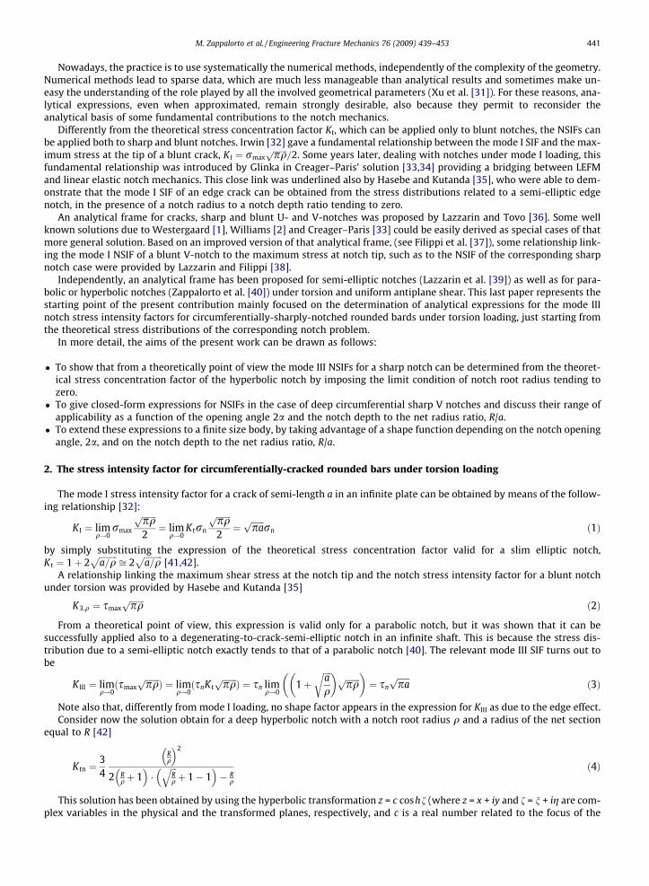
With reference to Fig. 1, when both a and R assumes finite values, KIII can be determined by means of the expression[21,43]
K III ¼ sn38
ffiffiffiffiffiffiffiffiffiffiffiffiffiffiffiffiffiffiffiffiffipRð1� kÞ
p1þ 1
2kþ 3
8k2 þ 5
16k3 þ 35
128k4 þ 0:208k5
� �¼ sn
38
ffiffiffiffiffiffiffiffiffiffiffiffiffiffiffiffiffiffiffiffiffipRð1� kÞ
p� fB—K ð7aÞ
where k ¼ RRþa and fB–K matches the expression between the square brackets.
Eq. (7a) has found to be accurate within 3% [21,30]. The accuracy was further increased by Noda and Takase who pro-posed a modified version of Eq. (7a) [30]
K III ¼ sn38
ffiffiffiffiffiffiffiffiffiffiffiffiffiffiffiffiffiffiffiffiffipRð1� kÞ
p� fB—K � ð1:009� 0:19064 � eþ 1:2326 � e2 � 2:7484 � e3 þ 2:7081 � e4 � 1:0024 � e5Þ ð7bÞ
where now e ¼ aRþa.
3. Analytical solutions for the notch stress intensity factors due to deep sharp V-notches under torsion
3.1. Solid section
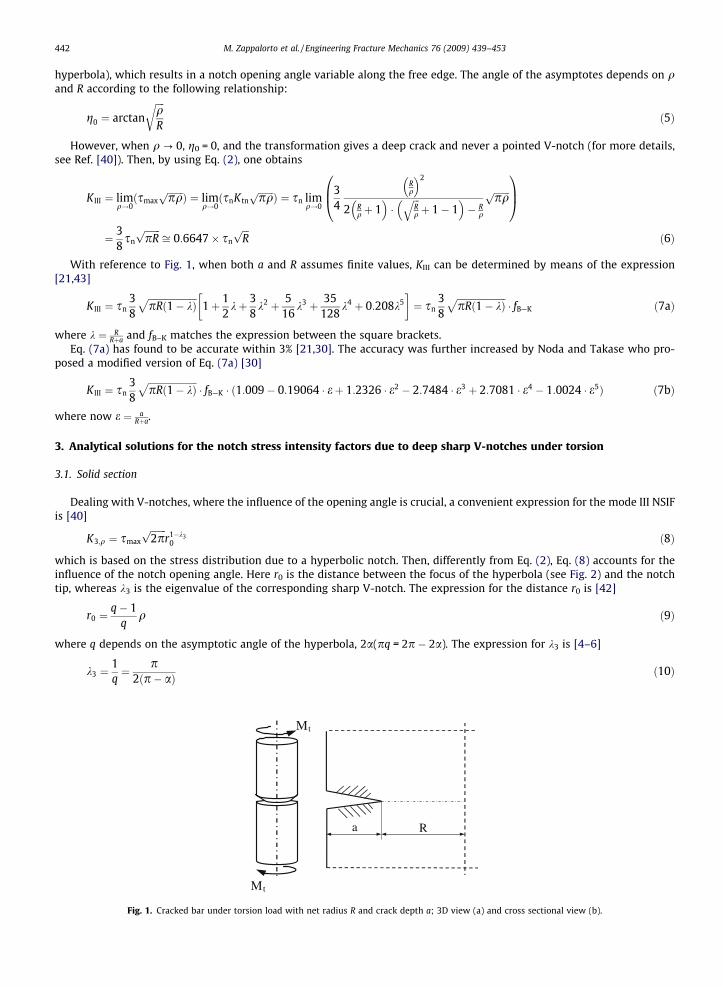
Dealing with V-notches, where the influence of the opening angle is crucial, a convenient expression for the mode III NSIFis [40]
K3;q ¼ smax
ffiffiffiffiffiffiffi2pp
r1�k30 ð8Þ
which is based on the stress distribution due to a hyperbolic notch. Then, differently from Eq. (2), Eq. (8) accounts for theinfluence of the notch opening angle. Here r0 is the distance between the focus of the hyperbola (see Fig. 2) and the notchtip, whereas k3 is the eigenvalue of the corresponding sharp V-notch. The expression for the distance r0 is [42]
r0 ¼q� 1
qq ð9Þ
where q depends on the asymptotic angle of the hyperbola, 2a(pq = 2p � 2a). The expression for k3 is [4–6]
k3 ¼1q¼ p
2ðp� aÞ ð10Þ
Mt
Mt
R a
Fig. 1. Cracked bar under torsion load with net radius R and crack depth a; 3D view (a) and cross sectional view (b).
y
xϕ
τzr
τzϕ
r0
r
u
u=u0
x
y
u = 0
-ϕ/q
a b
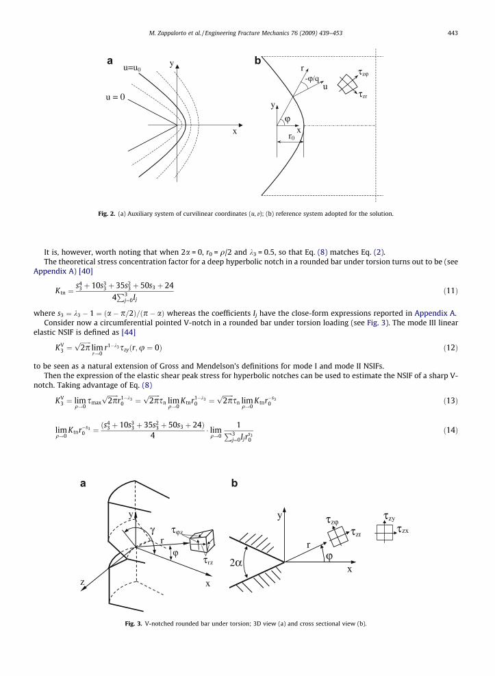
Fig. 2. (a) Auxiliary system of curvilinear coordinates (u,v); (b) reference system adopted for the solution.
M. Zappalorto et al. / Engineering Fracture Mechanics 76 (2009) 439–453 443
It is, however, worth noting that when 2a = 0, r0 = q/2 and k3 = 0.5, so that Eq. (8) matches Eq. (2).The theoretical stress concentration factor for a deep hyperbolic notch in a rounded bar under torsion turns out to be (see
Appendix A) [40]
Ktn ¼s4
3 þ 10s33 þ 35s2
3 þ 50s3 þ 24
4P3
j¼0Ij
ð11Þ
where s3 ¼ k3 � 1 ¼ ða� p=2Þ=ðp� aÞ whereas the coefficients Ij have the close-form expressions reported in Appendix A.Consider now a circumferential pointed V-notch in a rounded bar under torsion loading (see Fig. 3). The mode III linear
elastic NSIF is defined as [44]
KV3 ¼
ffiffiffiffiffiffiffi2pp
limr!0
r1�k3szyðr;u ¼ 0Þ ð12Þ
to be seen as a natural extension of Gross and Mendelson’s definitions for mode I and mode II NSIFs.Then the expression of the elastic shear peak stress for hyperbolic notches can be used to estimate the NSIF of a sharp V-
notch. Taking advantage of Eq. (8)
KV3 ¼ lim
q!0smax
ffiffiffiffiffiffiffi2pp
r1�k30 ¼
ffiffiffiffiffiffiffi2pp
sn limq!0
Ktnr1�k30 ¼
ffiffiffiffiffiffiffi2pp
sn limq!0
Ktnr�s30 ð13Þ
limq!0
Ktnr�s30 ¼ ðs
43 þ 10s3
3 þ 35s23 þ 50s3 þ 24Þ
4� lim
q!0
1P3j¼0Ijr
s30
ð14Þ
τrz
τϕz
ϕ
y
xz
r γ
τzϕτzr
ϕr
y
x2α
τzx
τzy
a b
Fig. 3. V-notched rounded bar under torsion; 3D view (a) and cross sectional view (b).
444 M. Zappalorto et al. / Engineering Fracture Mechanics 76 (2009) 439–453
Considering one by one the terms on the right hand side of Eq. (14), we have
limq!0
I0rs30 ¼ lim
k!0Rs3 ð6þ 24kþ 36k2 þ 24k3 þ 6k4Þ ¼ 6Rs3 ð15Þ
limq!0
I1rs30 ¼ lim
r0!0� r1þs3
0
R24þ 26s3 þ 9s2
3 þ s33 þ 24
/ lim
r0!0� rk3
0
R¼ 0 ð16Þ
limq!0
I2rs30 ¼ lim
r0!0� r2þs3
0
R2 ð36þ 21s3 þ 3s23Þ ¼ 0 ð17Þ
limq!0
I2rs30 ¼ lim
r0!0� r3þs3
0
R3 ð24þ 6s3Þ � 6r4þs3
0
R4
" #¼ 0 ð18Þ
Then it is easy to obtain the expression of the NSIF normalised with respect to the nominal shear stress on the net sec-tional area
�KV3 ¼
KV3
sn¼
ffiffiffiffiffiffiffi2pp s4
3 þ 10s33 þ 35s2
3 þ 50s3 þ 2424
R1�k3 ð19Þ
as well as the non-dimensional shape factor k3d
k3d ¼�KV
3
R1�k3¼
ffiffiffiffiffiffiffi2pp s4
3 þ 10s33 þ 35s2
3 þ 50s3 þ 2424
ð20Þ
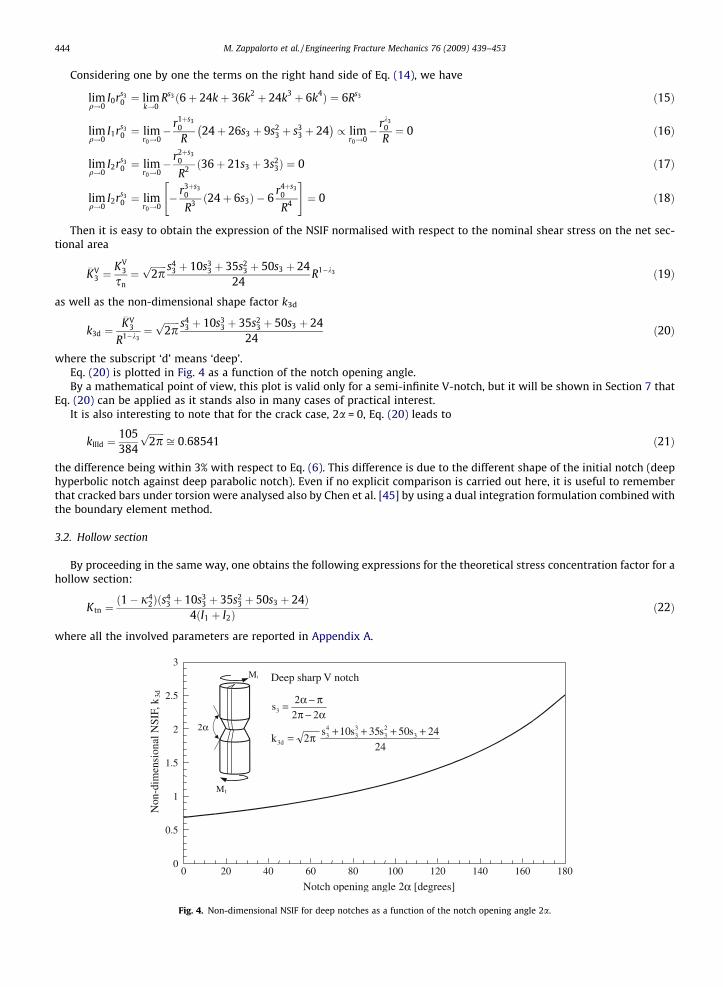
where the subscript ‘d’ means ‘deep’.Eq. (20) is plotted in Fig. 4 as a function of the notch opening angle.By a mathematical point of view, this plot is valid only for a semi-infinite V-notch, but it will be shown in Section 7 that
Eq. (20) can be applied as it stands also in many cases of practical interest.It is also interesting to note that for the crack case, 2a = 0, Eq. (20) leads to
kIIId ¼105384
ffiffiffiffiffiffiffi2pp
ffi 0:68541 ð21Þ
the difference being within 3% with respect to Eq. (6). This difference is due to the different shape of the initial notch (deephyperbolic notch against deep parabolic notch). Even if no explicit comparison is carried out here, it is useful to rememberthat cracked bars under torsion were analysed also by Chen et al. [45] by using a dual integration formulation combined withthe boundary element method.
3.2. Hollow section
By proceeding in the same way, one obtains the following expressions for the theoretical stress concentration factor for ahollow section:
Ktn ¼ð1� j4
2Þðs43 þ 10s3
3 þ 35s23 þ 50s3 þ 24Þ
4ðI1 þ I2Þð22Þ
where all the involved parameters are reported in Appendix A.
0
0.5
1
1.5
2
2.5
3
0 20 40 60 80 100 120 140 160 180
Notch opening angle 2α [degrees]
Non
-dim
ensi
onal
NSI
F, k
3d
2α
Mt
Mt
Deep sharp V notch
24
24s50s35s10s2k 3
23
33
43
d3
++++π=
α−ππ−α=
22
2s3
Fig. 4. Non-dimensional NSIF for deep notches as a function of the notch opening angle 2a.
M. Zappalorto et al. / Engineering Fracture Mechanics 76 (2009) 439–453 445
Then, by means of Eq. (8) one obtains the following expression for the NSIFs normalised with respect to the nominal shearstress on net sectional area:
�KV3 ¼
ffiffiffiffiffiffiffi2pp ð1� j4
2Þðs43 þ 10s3
3 þ 35s23 þ 50s3 þ 24Þ
4ð1� j2Þ1þs3 ½6þ 6j2ð1þ s3Þ þ 3j22ð2þ 3s3 þ s2
3Þ þ j32ð6þ 11s3 þ 6s2
3 þ s33Þ�
R1�k3 ð23Þ
as well as for the non-dimensional parameter
k3h ¼�KV
3
R1�k3¼
ffiffiffiffiffiffiffi2pp ð1� j4
2Þðs43 þ 10s3
3 þ 35s23 þ 50s3 þ 24Þ
4ð1� j2Þ1þs3 ½6þ 6j2ð1þ s3Þ þ 3j22ð2þ 3s3 þ s2
3Þ þ j32ð6þ 11s3 þ 6s2
3 þ s33Þ�
ð24Þ
Note that, if Ri = 0, then j2 = 0, and Eqs. (23) and (24) matches Eqs. (19) and (20), respectively.
4. Notch stress intensity factors for shallow sharp V-notches in solid bars under torsion
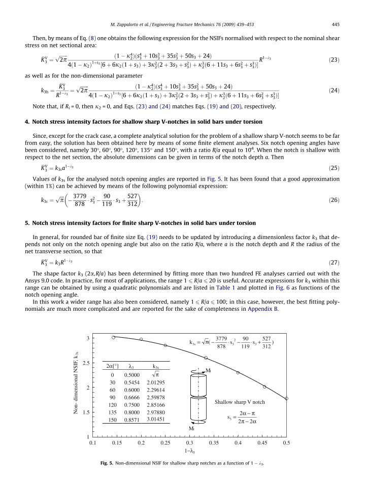
Since, except for the crack case, a complete analytical solution for the problem of a shallow sharp V-notch seems to be farfrom easy, the solution has been obtained here by means of some finite element analyses. Six notch opening angles havebeen considered, namely 30�, 60�, 90�, 120�, 135� and 150�, with a ratio R/a equal to 104. When the notch is shallow withrespect to the net section, the absolute dimensions can be given in terms of the notch depth a. Then
�KV3 ¼ k3sa1�k3 ð25Þ
Values of k3s for the analysed notch opening angles are reported in Fig. 5. It has been found that a good approximation(within 1%) can be achieved by means of the following polynomial expression:
k3s ¼ffiffiffiffipp
�3779878
� s23 �
90119� s3 þ
527312
� �: ð26Þ
5. Notch stress intensity factors for finite sharp V-notches in solid bars under torsion
In general, for rounded bar of finite size Eq. (19) needs to be updated by introducing a dimensionless factor k3 that de-pends not only on the notch opening angle but also on the ratio R/a, where a is the notch depth and R the radius of thenet transverse section, so that
�KV3 ¼ k3R1�k3 ð27Þ
The shape factor k3 (2a,R/a) has been determined by fitting more than two hundred FE analyses carried out with theAnsys 9.0 code. In practice, for most of applications, the range 1 6 R/a 6 20 is useful. Accurate expressions for k3 within thisrange can be obtained by using a quadratic polynomials and are listed in Table 1 and plotted in Fig. 6 as functions of thenotch opening angle.
In this work a wider range has also been considered, namely 1 6 R/a 6 100; in this case, however, the best fitting poly-nomials are much more complicated and are reported for the sake of completeness in Appendix B.
2α[°] λ3 k3s
0 0.5000 π30 0.5454 2.01295 60 0.6000 2.29614 90 0.6666 2.59878
120 0.7500 2.85166 135 0.8000 2.97880 150 0.8571 3.01451
1
1.5
2
2.5
3
0.1 0.15 0.2 0.25 0.3 0.35 0.4 0.45 0.5
1−λ3
Mt
Mt
)312
527s
119
90s
878
3779(πk 3
23s3 +⋅−⋅−=
Shallow sharp V notch
α−ππ−α=
22
2s3
Non
- di
men
sion
al N
SIF,
k3s
Fig. 5. Non-dimensional NSIF for shallow sharp notches as a function of 1 � k3.
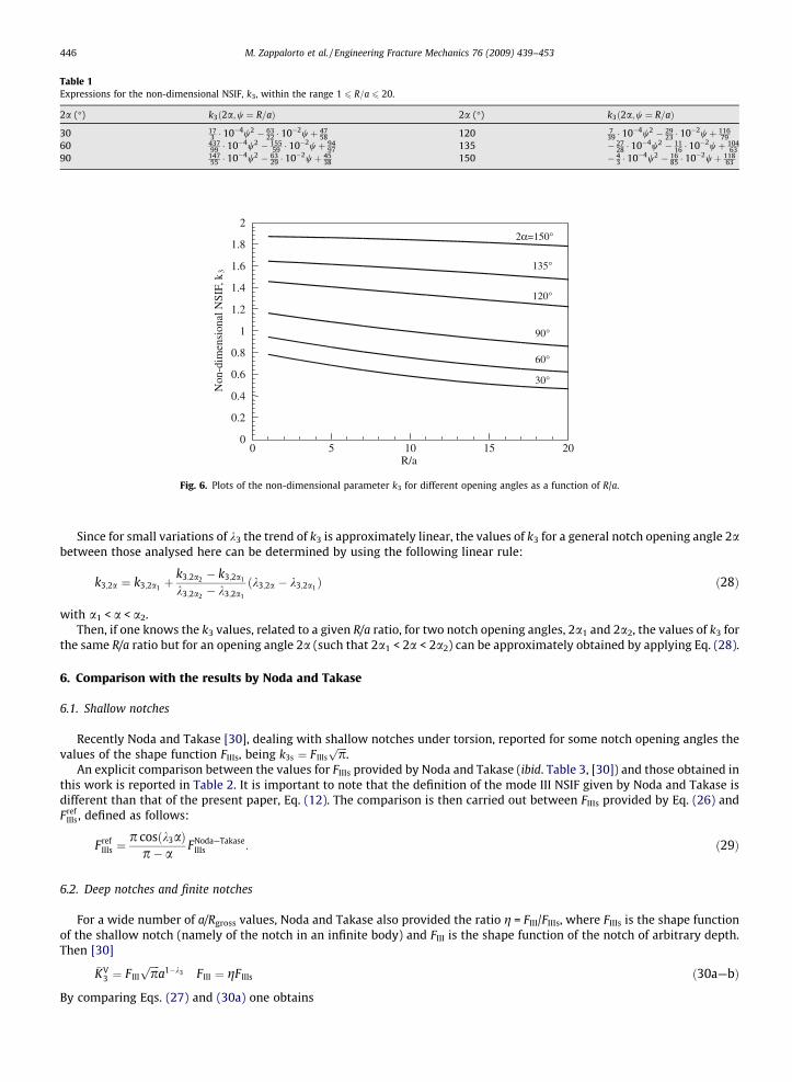
Table 1Expressions for the non-dimensional NSIF, k3, within the range 1 6 R=a 6 20.
2a (�) k3ð2a;w ¼ R=aÞ 2a (�) k3ð2a;w ¼ R=aÞ
30 173 � 10�4w2 � 63
22 � 10�2wþ 4758 120 7
39 � 10�4w2 � 2923 � 10�2wþ 116
7960 437
99 � 10�4w2 � 15559 � 10�2wþ 94
97 135 � 2728 � 10�4w2 � 11
16 � 10�2wþ 10463
90 14755 � 10�4w2 � 63
29 � 10�2wþ 4538 150 � 4
3 � 10�4w2 � 1685 � 10�2wþ 118
63
0
0.2
0.4
0.6
0.8
1
1.2
1.4
1.6
1.8
2
0 5 10 15 20 R/a
Non
-dim
ensi
onal
NSI
F, k
3
30°
135°
120°
90°
60°
2α=150°
Fig. 6. Plots of the non-dimensional parameter k3 for different opening angles as a function of R/a.
446 M. Zappalorto et al. / Engineering Fracture Mechanics 76 (2009) 439–453
Since for small variations of k3 the trend of k3 is approximately linear, the values of k3 for a general notch opening angle 2abetween those analysed here can be determined by using the following linear rule:
k3;2a ¼ k3;2a1 þk3;2a2 � k3;2a1
k3;2a2 � k3;2a1
ðk3;2a � k3;2a1 Þ ð28Þ
with a1 < a < a2.Then, if one knows the k3 values, related to a given R/a ratio, for two notch opening angles, 2a1 and 2a2, the values of k3 for
the same R/a ratio but for an opening angle 2a (such that 2a1 < 2a < 2a2) can be approximately obtained by applying Eq. (28).
6. Comparison with the results by Noda and Takase
6.1. Shallow notches
Recently Noda and Takase [30], dealing with shallow notches under torsion, reported for some notch opening angles thevalues of the shape function FIIIs, being k3s ¼ FIIIs
ffiffiffiffipp
.An explicit comparison between the values for FIIIs provided by Noda and Takase (ibid. Table 3, [30]) and those obtained in
this work is reported in Table 2. It is important to note that the definition of the mode III NSIF given by Noda and Takase isdifferent than that of the present paper, Eq. (12). The comparison is then carried out between FIIIs provided by Eq. (26) andFref
IIIs, defined as follows:
FrefIIIs ¼
p cosðk3aÞp� a
FNoda—TakaseIIIs : ð29Þ
6.2. Deep notches and finite notches
For a wide number of a/Rgross values, Noda and Takase also provided the ratio g = FIII/FIIIs, where FIIIs is the shape functionof the shallow notch (namely of the notch in an infinite body) and FIII is the shape function of the notch of arbitrary depth.Then [30]
�KV3 ¼ F III
ffiffiffiffipp
a1�k3 F III ¼ gF IIIs ð30a—bÞ
By comparing Eqs. (27) and (30a) one obtains
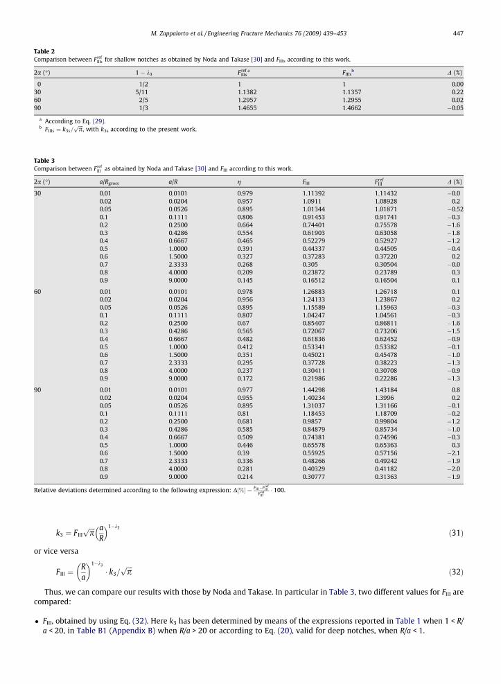
Table 2Comparison between Fref
IIIs for shallow notches as obtained by Noda and Takase [30] and FIIIs according to this work.
2a (�) 1 � k3 FrefIIIs
a FIIIsb D (%)
0 1/2 1 1 0.0030 5/11 1.1382 1.1357 0.2260 2/5 1.2957 1.2955 0.0290 1/3 1.4655 1.4662 �0.05
a According to Eq. (29).b FIIIs ¼ k3s=
ffiffiffiffipp
, with k3s according to the present work.
Table 3Comparison between Fref
III as obtained by Noda and Takase [30] and FIII according to this work.
2a (�) a/Rgross a/R g FIII FrefIII D (%)
30 0.01 0.0101 0.979 1.11392 1.11432 �0.00.02 0.0204 0.957 1.0911 1.08928 0.20.05 0.0526 0.895 1.01344 1.01871 �0.520.1 0.1111 0.806 0.91453 0.91741 �0.30.2 0.2500 0.664 0.74401 0.75578 �1.60.3 0.4286 0.554 0.61903 0.63058 �1.80.4 0.6667 0.465 0.52279 0.52927 �1.20.5 1.0000 0.391 0.44337 0.44505 �0.40.6 1.5000 0.327 0.37283 0.37220 0.20.7 2.3333 0.268 0.305 0.30504 �0.00.8 4.0000 0.209 0.23872 0.23789 0.30.9 9.0000 0.145 0.16512 0.16504 0.1
60 0.01 0.0101 0.978 1.26883 1.26718 0.10.02 0.0204 0.956 1.24133 1.23867 0.20.05 0.0526 0.895 1.15589 1.15963 �0.30.1 0.1111 0.807 1.04247 1.04561 �0.30.2 0.2500 0.67 0.85407 0.86811 �1.60.3 0.4286 0.565 0.72067 0.73206 �1.50.4 0.6667 0.482 0.61836 0.62452 �0.90.5 1.0000 0.412 0.53341 0.53382 �0.10.6 1.5000 0.351 0.45021 0.45478 �1.00.7 2.3333 0.295 0.37728 0.38223 �1.30.8 4.0000 0.237 0.30411 0.30708 �0.90.9 9.0000 0.172 0.21986 0.22286 �1.3
90 0.01 0.0101 0.977 1.44298 1.43184 0.80.02 0.0204 0.955 1.40234 1.3996 0.20.05 0.0526 0.895 1.31037 1.31166 �0.10.1 0.1111 0.81 1.18453 1.18709 �0.20.2 0.2500 0.681 0.9857 0.99804 �1.20.3 0.4286 0.585 0.84879 0.85734 �1.00.4 0.6667 0.509 0.74381 0.74596 �0.30.5 1.0000 0.446 0.65578 0.65363 0.30.6 1.5000 0.39 0.55925 0.57156 �2.10.7 2.3333 0.336 0.48266 0.49242 �1.90.8 4.0000 0.281 0.40329 0.41182 �2.00.9 9.0000 0.214 0.30777 0.31363 �1.9
Relative deviations determined according to the following expression: D½%� ¼ FIII�FrefIII
FrefIII� 100.
M. Zappalorto et al. / Engineering Fracture Mechanics 76 (2009) 439–453 447
k3 ¼ F IIIffiffiffiffipp a
R
� �1�k3
ð31Þ
or vice versa
F III ¼Ra
� �1�k3
� k3=ffiffiffiffipp
ð32Þ
Thus, we can compare our results with those by Noda and Takase. In particular in Table 3, two different values for FIII arecompared:
� FIII, obtained by using Eq. (32). Here k3 has been determined by means of the expressions reported in Table 1 when 1 < R/a < 20, in Table B1 (Appendix B) when R/a > 20 or according to Eq. (20), valid for deep notches, when R/a < 1.
448 M. Zappalorto et al. / Engineering Fracture Mechanics 76 (2009) 439–453
� FrefIII , obtained by using (30b) with FIIIs ¼ Fref
IIIs, as obtained from Eq. (29), and g according to Noda and Takase (ibid. Table 9,[30]).
It is evident that the agreement is very good (the maximum difference being 2%).
7. Results of Fe analyses and final discussion
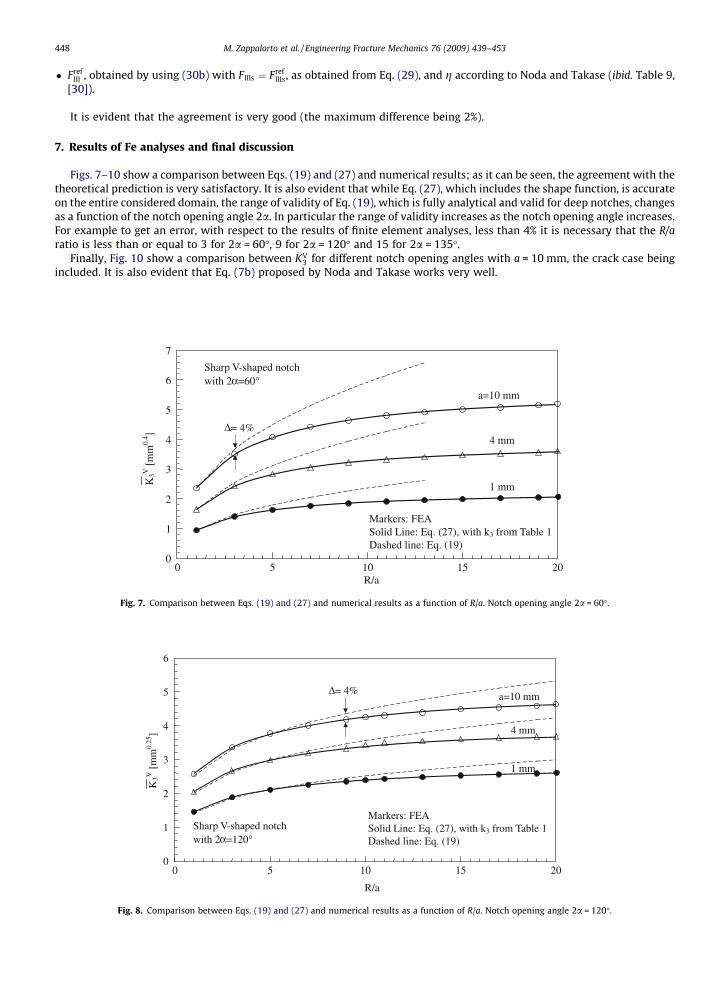
Figs. 7–10 show a comparison between Eqs. (19) and (27) and numerical results; as it can be seen, the agreement with thetheoretical prediction is very satisfactory. It is also evident that while Eq. (27), which includes the shape function, is accurateon the entire considered domain, the range of validity of Eq. (19), which is fully analytical and valid for deep notches, changesas a function of the notch opening angle 2a. In particular the range of validity increases as the notch opening angle increases.For example to get an error, with respect to the results of finite element analyses, less than 4% it is necessary that the R/aratio is less than or equal to 3 for 2a = 60�, 9 for 2a = 120� and 15 for 2a = 135�.
Finally, Fig. 10 show a comparison between �KV3 for different notch opening angles with a = 10 mm, the crack case being
included. It is also evident that Eq. (7b) proposed by Noda and Takase works very well.
0
1
2
3
4
5
6
7
0 5 10 15 20R/a
Sharp V-shaped notchwith 2 α=60°
Markers: FEASolid Line: Eq. (27), with k3 from Table 1 Dashed line: Eq. (19)
Δ= 4%
a=10 mm
4 mm
1 mm K3V
[m
m0.
4 ]
Fig. 7. Comparison between Eqs. (19) and (27) and numerical results as a function of R/a. Notch opening angle 2a = 60�.
0
1
2
3
4
5
6
0 5 10 15 20
R/a
Sharp V-shaped notch with 2 α=120°
Markers: FEASolid Line: Eq. (27), with k3 from Table 1Dashed line: Eq. (19)
Δ= 4% a=10 mm
4 mm
1 mm
K3V
[m
m0.
25]
Fig. 8. Comparison between Eqs. (19) and (27) and numerical results as a function of R/a. Notch opening angle 2a = 120�.

2
3
4
5
0 5 10 15 20R/a
a=10 mm
Eq. (27), with k3 from Table 1
2α=60°
2α=90°
2α=120°
2α=135°
2α=150°
Crack
Eq. (7b)
Eq. (7a)
K3V
[m
m1-
λ 3 ]
Fig. 10. Comparison between Eqs. (7a), (7b), and (27) and numerical results, with notch depth a = 10 mm and notch opening angle 2a.
0
1
2
3
4
5
0 5 10 15 20R/a
Sharp V-shaped notch with 2 α=135°
Markers: FEASolid Line: Eq. (27), with k3 from Table 1 Dashed line: Eq. (19)
a=10 mm
4 mm
1 mm
Δ= 4%
K3V
[m
m0.
2 ]
Fig. 9. Comparison between Eqs. (19) and (27) and numerical results as a function of R/a. Notch opening angle 2a = 135�.
M. Zappalorto et al. / Engineering Fracture Mechanics 76 (2009) 439–453 449
8. Conclusion
Analytical expressions for the notch stress intensity factors as due to deep circumferential sharp V-notches under torsionloading have been found starting from the expressions of the theoretical stress concentration factor of a hyperbolic notch.The hyperbolic notch allows us to account for the influence of the V-notch opening angle, which is not included when a par-abolic notch is considered.
The work confirms the existence of an explicit analytical link between the theoretical stress concentration factor for anotch and the notch stress intensity factor of the corresponding sharp V-notch feature, that are, instead, by a theoreticalpoint of view often thought as different and independent.
By staring from these analytical bases, the expressions have been improved to account for the finite dimension of thenotch. Simple practical expressions have been determined by means of a numerical best fitting procedure, which have beenproved to be in good agreement with the results of a large body of finite element analyses.
Appendix A. Closed-form solutions of stress distributions for hyperbolic and parabolic notches
Consider the following transformation [42]:
z ¼ wq ðA:1Þ
450 M. Zappalorto et al. / Engineering Fracture Mechanics 76 (2009) 439–453
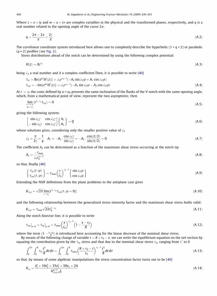
Where z ¼ xþ iy and w ¼ uþ iv are complex variables in the physical and the transformed planes, respectively, and q is areal number related to the opening angle of the curve 2a:
q ¼ 2p� 2ap
¼ 2cp
ðA:2Þ
The curvilinear coordinate system introduced here allows one to completely describe the hyperbolic (1 < q < 2) or parabolic(q = 2) profiles (see Fig. 2).
Stress distributions ahead of the notch can be determined by using the following complex potential:
HðzÞ ¼ Azk3 ðA:3Þ
being k3 a real number and A a complex coefficient.Then, it is possible to write [40]
szr ¼ RefeiuH0ðzÞg ¼ k3rk3�1ð�A2 sin k3uþ A1 cos k3uÞszu ¼ �ImfeiuH0ðzÞg ¼ k3rk3�1ð�A1 sin k3u� A2 cos k3uÞ ðA:4Þ
At r ?1 the conic defined by u = u0 presents the same inclination of the flanks of the V-notch with the same opening angle,which, from a mathematical point of view, represent the two asymptotes; then
limr!þ1u!�c
ðr1�k3szuÞ ¼ 0 ðA:5Þ
giving the following system:
sin k3c cos k3c� sin k3c cos k3c
� �A1
A2
� �¼ 0 ðA:6Þ
whose solutions gives, considering only the smaller positive value of k3
k3 ¼p2c¼ 1
qA1 ¼ �A2 �
cos k3csin k3c
¼ �A2 �cosðp=2Þsinðp=2Þ ¼ 0 ðA:7Þ
The coefficient A2 can be determined as a function of the maximum shear stress occurring at the notch tip
A2 ¼�smax
k3rk3�10
ðA:8Þ
so that, finally [40]
szrðr;uÞszuðr;uÞ
� �¼ smax
rr0
� �k3�1 sin k3ucos k3u
� �ðA:9Þ
Extending the NSIF definitions from the plane problems to the antiplane case gives
K3;q ¼ffiffiffiffiffiffiffi2pp
limr!rþo½r1�k3szuðr;u ¼ 0Þ� ðA:10Þ
and the following relationship between the generalized stress intensity factor and the maximum shear stress holds valid:
K3;q ¼ smax
ffiffiffiffiffiffiffi2pp
r1�k30 ðA:11Þ
Along the notch bisector line, it is possible to write
szu
y¼0 ¼ szy
y¼0 ¼ smax
xr0
� �k3�1
1� x� r0
R
� �ðA:12Þ
where the term 1� x�r0R
is introduced here accounting for the linear decrease of the nominal shear stress.
By means of the following change of variable t ¼ Rþ r0 � x; we can write the equilibrium equation on the net section byequating the contribution given by the szy stress and that due to the nominal shear stress sn, ranging from s* to 0
Z 2p0
Z R
0sn
t3
Rdt dh ¼
Z 2p
0
Z R
0smax
Rþ r0 � tr0
� �k3�1 t3
Rdt dh ðA:13Þ
so that, by means of some algebraic manipulations the stress concentration factor turns out to be [40]
Ktn ¼s4
3 þ 10s33 þ 35s2
3 þ 50s3 þ 24
4P3
j¼0Ij
ðA:14Þ

M. Zappalorto et al. / Engineering Fracture Mechanics 76 (2009) 439–453 451
where
s3 ¼ s3ð2aÞ ¼ k3 � 1 k ¼ kðr0;RÞ ¼r0
R
I0 ¼ 1þ 1k
� �s3
½6þ 24kþ 36k2 þ 24k3 þ 6k4�
I1 ¼ �kð24þ 26s3 þ 9s23 þ s3
3ÞI2 ¼ �k2ð36þ 21s3 þ 3s2
3ÞI3 ¼ �k3ð24þ 6s3Þ � 6k4
ðA:15Þ
Consider now a hollow section (see Fig. A1), the expression for Kt becomes
Ktn ¼R4
n4 �
R4i
4R Rn
Ri
Rnþr0�tr0
� �k3�1t3dt
ðA:16Þ
that is
Ktn ¼ð1� j4
2Þðs43 þ 10s3
3 þ 35s23 þ 50s3 þ 24Þ
4ðI1 þ I2ÞðA:17Þ
where
s3ð2aÞ ¼ k3 � 1
j1ðq;RÞ ¼r0
Rn
j2ðq;RÞ ¼Ri
Rn
I1 ¼ ð1þ j1 � j2Þ1þ j1 � j2
j1
� �s3
6ðj1 þ 1Þ3h
þ 6j2ðj1 þ 1Þ2ð1þ s3Þ þ 3j22ðj1 þ 1Þð2þ 3s3 þ s2
3Þ
þj32ð6þ 11s3 þ 6s2
3 þ s33Þ�
I2 ¼ �j1 6j31 þ 6j2
1ð4þ s3Þ þ 3j1ð12þ 7s3 þ s23Þ þ 24þ 26s3 þ 9s2
3 þ s33
� �
ðA:18Þ
being Rn and Ri respectively the external and the internal radius of the net section (see Fig. A1)
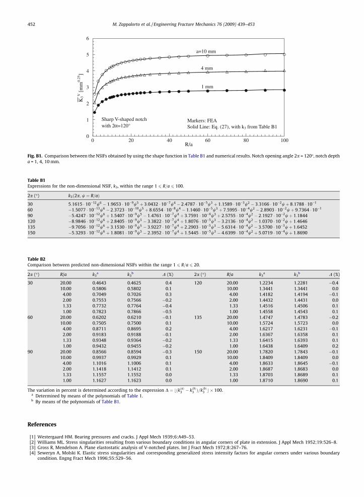
Appendix B. Expressions for the non-dimensional NSIF k3 within the range 1 <R=a <100
When R/a > 20 the quadratic polynomials given in Table 1 are not accurate enough and may cause unacceptable errors inthe k3 prediction, the entity of the error depending also on the notch opening angle. Then we have determined new expres-sions to fit numerical results on the wider range 1 r=a 100, which are reported in Table B1. A comparison with numericalresults is shown in Fig. B1.
Do note that, in the range 1 6 R/a 6 20, the polynomials in Table 1 and those in Table B1 give results very closed to eachother, with a maximum difference equal to 0.5% (see Table B2).
Mt
Mt
y
xϕ
r0
r
u-ϕ/q
Ri
Rn Axi
s of
sim
met
ry
Fig. A1. Notched shaft with a hollow section.
0
1
2
3
4
5
6
0 20 40 60 80 100R/a
Sharp V-shaped notch with 2 α=120°
Markers: FEASolid Line: Eq. (27), with k3 from Table B1
K3V
[m
m0.
25]
1 mm
4 mm
a=10 mm
Fig. B1. Comparison between the NSIFs obtained by using the shape function in Table B1 and numerical results. Notch opening angle 2a = 120�, notch deptha = 1, 4, 10 mm.
Table B2Comparison between predicted non-dimensional NSIFs within the range 1 6 R=a 6 20.
2a (�) R/a k3a k3
b D (%) 2a (�) R/a k3a k3
b D (%)
30 20.00 0.4643 0.4625 0.4 120 20.00 1.2234 1.2281 �0.410.00 0.5806 0.5802 0.1 10.00 1.3441 1.3441 0.0
4.00 0.7049 0.7026 0.3 4.00 1.4182 1.4194 �0.12.00 0.7553 0.7566 �0.2 2.00 1.4432 1.4431 0.01.33 0.7732 0.7764 �0.4 1.33 1.4516 1.4506 0.11.00 0.7823 0.7866 �0.5 1.00 1.4558 1.4543 0.1
60 20.00 0.6202 0.6210 �0.1 135 20.00 1.4747 1.4783 �0.210.00 0.7505 0.7500 0.1 10.00 1.5724 1.5723 0.0
4.00 0.8711 0.8695 0.2 4.00 1.6217 1.6231 �0.12.00 0.9183 0.9188 �0.1 2.00 1.6367 1.6358 0.11.33 0.9348 0.9364 �0.2 1.33 1.6415 1.6393 0.11.00 0.9432 0.9455 �0.2 1.00 1.6438 1.6409 0.2
90 20.00 0.8566 0.8594 �0.3 150 20.00 1.7820 1.7843 �0.110.00 0.9937 0.9929 0.1 10.00 1.8409 1.8409 0.0
4.00 1.1016 1.1006 0.1 4.00 1.8633 1.8645 �0.12.00 1.1418 1.1412 0.1 2.00 1.8687 1.8683 0.01.33 1.1557 1.1552 0.0 1.33 1.8703 1.8689 0.11.00 1.1627 1.1623 0.0 1.00 1.8710 1.8690 0.1
The variation in percent is determined according to the expression D ¼ bðkðaÞ3 � kðbÞ3 Þ=kðbÞ3 c � 100.a Determined by means of the polynomials of Table 1.b By means of the polynomials of Table B1.
Table B1Expressions for the non-dimensional NSIF, k3, within the range 1 6 R=a 6 100.
2a (�) k3ð2a; w ¼ R=aÞ
30 5:1615 � 10�12w6 � 1:9653 � 10�9w5 þ 3:0432 � 10�7w4 � 2:4787 � 10�5w3 þ 1:1589 � 10�3w2 � 3:3166 � 10�2wþ 8:1788 � 10�1
60 �1:5077 � 10�13w6 � 2:3723 � 10�10w5 þ 8:6554 � 10�8w4 � 1:1460 � 10�5w3 þ 7:5995 � 10�4w2 � 2:8903 � 10�2wþ 9:7364 � 10�1
90 �5:4247 � 10�12w6 þ 1:5407 � 10�9w5 � 1:4761 � 10�7w4 þ 3:7591 � 10�6w3 þ 2:5755 � 10�4w2 � 2:1927 � 10�2wþ 1:1844120 �8:9846 � 10�12w6 þ 2:8405 � 10�9w5 � 3:3822 � 10�7w4 þ 1:8076 � 10�5w3 � 3:2136 � 10�4w2 � 1:0370 � 10�2wþ 1:4646135 �9:7056 � 10�12w6 þ 3:1530 � 10�9w5 � 3:9227 � 10�7w4 þ 2:2903 � 10�5w3 � 5:6314 � 10�4w2 � 3:5700 � 10�3wþ 1:6452150 �5:3293 � 10�12w6 þ 1:8081 � 10�9w5 � 2:3952 � 10�7w4 þ 1:5445 � 10�5w3 � 4:6399 � 10�4w2 þ 5:0719 � 10�4wþ 1:8690
452 M. Zappalorto et al. / Engineering Fracture Mechanics 76 (2009) 439–453
References
[1] Westergaard HM. Bearing pressures and cracks. J Appl Mech 1939;6:A49–53.[2] Williams ML. Stress singularities resulting from various boundary conditions in angular corners of plate in extension. J Appl Mech 1952;19:526–8.[3] Gross R, Mendelson A. Plane elastostatic analysis of V-notched plates. Int J Fract Mech 1972;8:267–76.[4] Seweryn A, Molski K. Elastic stress singularities and corresponding generalized stress intensity factors for angular corners under various boundary
condition. Engng Fract Mech 1996;55:529–56.
M. Zappalorto et al. / Engineering Fracture Mechanics 76 (2009) 439–453 453
[5] Dunn ML, Suwito W, Cunningham S. Stress intensities at notch singularities. Engng Fract Mech 1997;57:417–30.[6] Qian J, Hasebe N. Property of Eigenvalues and eigenfunctions for an interface V-notch in antiplane elasticity. Engng Fract Mech 1997;56:729–34.[7] Nui LS, Chehimi C, Pluvinage G. Stress field near a large blunted tip V-notch and application of the concept of the critical notch stress intensity factor
(NSIF) to the fracture toughness of very brittle materials. Engng Fract Mech 1994;49:325–35.[8] Dunn ML, Suwito W, Cunningham S. Fracture initiation at sharp notches: correlation using critical stress intensities. Int J Solid Struct
1997;34:3873–83.[9] Dunn ML, Suwito W, Cunningham S, May CW. Fracture initiation at sharp notches under mode I, mode II, and mild mixed mode loading. Int J Fracture
1997;84:367–81.[10] Gómez FJ, Elices M. Fracture of components with V-shaped notches. Engng Fract Mech 2003;70:1913–27.[11] Gómez FJ, Elices M. A fracture criterion for sharp V-notched samples. Int J Fracture 2003;123:163–75.[12] Boukharouba T, Tamine T, Nui L, Chehimi C, Pluvinage G. The use of notch stress intensity factor as a fatigue crack initiation parameter. Engng Fract
Mech 1995;52:503–12.[13] Verreman Y, Nie B. Early development of fatigue cracking at manual fillet welds. Fatigue Fract Engng Mater Struct 1996;19:669–81.[14] Lazzarin P, Tovo R. A notch intensity approach to the stress analysis of welds. Fatigue Fract Engng Mater Struct 1998;21:1089–104.[15] Atzori B, Lazzarin P, Tovo R. From a local stress approach to fracture mechanics: a comprehensive evaluation of the fatigue strength of welded joints.
Fatigue Fract Engng Mater Struct 1999;22:369–82.[16] Lazzarin P, Livieri P. Notch stress intensity factors and fatigue strength of aluminium and steel welded joints. Int J Fatigue 2001;23:225–32.[17] Reedy Jr ED. Asymptotic interface-corner solutions for butt tensile joints. Int J Solid Struct 1993;30:767–77.[18] Reedy Jr ED, Guess TR. Comparison of butt tensile strength data with interface corner stress intensity factor prediction. Int J Solid Struct
1993;30:2929–36.[19] Aliabadi MH, Rooke DP. Numerical fracture mechanics. Dordrecht: Kluwer Academic Publishers; 1991.[20] Anderson TL. Fracture mechanics, fundamental and application. New York: CRC press; 2005.[21] Tada H, Paris CP, Irwin GR. The stress analysis of cracks handbook. 3rd ed. New York: ASME; 2000.
[22] Murakami Y. Stress intensity factors handbook, vols. 4–5. Berlin: Springer; 2001.[23] Shin CS, Man KC, Wang CM. A practical method to estimate the stress concentration of notches. Int J Fatigue 1994;16:242–56.[24] Livieri P. A new path independent integral applied to notched components under mode I loadings. Int J Fracture 2003;123:107–25.[25] Zhao Z, Hahn HG. Determining the SIF of a V-notch from the results of a mixed-mode crack. Engng Fract Mech 1992;43:511–8.[26] Chen DH. Stress intensity factors for V-notched strip under tension or in-plane bending. Int J Fracture 1995;70:81–97.[27] Atzori B, Lazzarin P, Tovo R. Stress field parameters to predict the fatigue strength of notched components. J Strain Anal 1999;34:437–53.[28] Strandberg M. A numerical study of the elastic stress field arising from sharp and blunt V-notches in a SENT-specimen. Int J Fracture 1999;100:329–42.[29] Strandberg M. Upper bounds for the notch intensity factor for some geometries and their use in general interpolation formulae. Engng Fract Mech
2001;68:577–85.[30] Noda N, Takase Y. Generalized stress intensity factors for V-shaped notch in a round bar under torsion, tension and bending. Engng Fract Mech
2003;70:1447–66.[31] Xu RX, Thompson JC, Topper TH. Practical stress expressions for stress concentration regions. Fatigue Fract Engng Mater Struct 1995;18:885–95.[32] Irwin GR. Fracture. Handbuch der physik, vol. 6. Berlin: Springer; 1958. p. 551–90.[33] Creager M, Paris PC. Elastic field equations for blunt cracks with reference to stress corrosion cracking. Int J Fract Mech 1967;3:247–52.[34] Glinka G. Calculation of inelastic notch-tip strain-stress histories under cyclic loading. Engng Fract Mech 1985;22:839–54.[35] Hasebe N, Kutanda Y. Calculation of stress intensity factors from stress concentration factor. Engng Fract Mech 1978;10:215–21.[36] Lazzarin P, Tovo R. A unified approach to the evaluation of linear elastic stress fields in the neighborhood of cracks and notches. Int J Fracture
1996;78:3–19.[37] Filippi S, Lazzarin P, Tovo R. Developments of some explicit formulas useful to describe elastic stress fields ahead of notches in plates. Int J Solid Struct
2002;39:4543–65.[38] Lazzarin P, Filippi S. A generalised stress intensity factor to be applied to rounded V-shaped notches. Int J Solid Struct 2006;43:2461–78.[39] Lazzarin P, Zappalorto M, Yates JR. Analytical study of stress distributions due to semi-elliptic notches in shafts under torsion loading. Int J Engng Sci
2007;45:308–28.[40] Zappalorto M, Lazzarin P, Yates JR. Elastic stress distributions resulting from hyperbolic and parabolic notches in round shafts under torsion and
uniform antiplane shear loadings. Int J Solid Struct 2008;45:4879–901.[41] Inglis CE. Stresses in a plate due to the presence of cracks and sharp corners. Trans Inst Naval Arch 1913;55:219–30.[42] Neuber H. Theory of notch stresses. 2nd ed. Berlin: Splinger-Verlag; 1958.[43] Benthem JP, Koiter WT. In: Sih GC, editor. Mechanics of fracture 1. Noordhoff Int Pub 1; 1973. p. 131–78.[44] Lazzarin P, Sonsino CM, Zambardi R. A notch stress intensity approach to predict the fatigue behaviour of T butt welds between tube and flange when
subjected to in-phase bending and torsion loading. Fract Engng Mater Struct 2004;27:127–41.[45] Chen Jt, Chen KH, Yeih W, Shieh NC. Dual boundary element anaysis for cracked bars under torsion. Engng Computation 1998;15:732–49.


