Engineering Failure Analysis - download.xuebalib.comdownload.xuebalib.com/xuebalib.com.35456.pdf ·...
11
Contents lists available at ScienceDirect Engineering Failure Analysis journal homepage: www.elsevier.com/locate/engfailanal Analytical and experimental research on erosion wear law of drill pipe in gas drilling Zhiqiang Huang a,⁎ , Dou Xie a , Xiaobing Huang b , Gang Li a , Song Xie a a Electromechanic Engineering College, Southwest Petroleum University, Chengdu, Sichuan 610500, PR China b College of Mechanical Engineering, Panzhihua University, Panzhihua, Sichuan 617000, PR China ARTICLE INFO Keywords: Erosion wear Drill pipe Theoretical derivation Laboratory experiment Gas drilling ABSTRACT Erosion of drill pipe caused by the rock particles in annular space is very serious in gas drilling. The aim of this paper is to study the erosion wear law of drill pipe by theoretical derivation and laboratory experiment. Based on the micro-cutting model of single rock particle, the erosion model of drill pipe is established to calculate the erosion wear loss. This model establishes the relationship between the erosion wear loss of drill pipe and drilling parameters, such as gas injection volume and rate of penetration (ROP). The laboratory experiment is carried out to verify and revise the erosion model, and the results show that when ROP is less than 20 m/h, the erosion wear loss of drill pipe is approximatively proportional to the square of gas injection volume and has positive correlation with ROP. However, it has negative correlation with ROP when ROP is faster than 20 m/h. In addition, it is also obtained that gas injection volume has more impact on drill pipe erosion compared to ROP based on the analysis of an engineering example, and high ROP will suppress the erosion wear of drill pipe. Therefore, under the premise of satisfying the drilling requirements, employing lower gas injection volume and higher ROP can reduce drill pipe erosion in gas drilling, which will save the drilling cost greatly. 1. Introduction Gas drilling is a kind of under-balanced drilling technology using high-speed gas to carry cuttings to surface, which can improve the production capacity of oil gas well significantly [1]. However, high-speed cuttings-carrying flow erodes drill pipe persistently, especially for drill pipe joint [2]. It is clearly observed from Fig. 1 that cracks and erosion pits present on the drill pipe surface in gas drilling, easily causing drill pipe fracture and washout, or even personal casualty. The statistics show that the drill pipe would lose 1–10 kg/m due to flow erosion in gas drilling. Just in 2014, erosion wear accidents account for 65% of the total failure accidents of dill pipe in one gas field in China. Therefore, it has great practical value to study the erosion wear law, in order to reduce drill pipe erosion in gas drilling. Several scholars have studied the erosion phenomena and erosion profile prediction [3–7]. Their findings suggest that the velocity of erosion particles, material properties and impact angle are the most important factors of erosion [8]. In addition, some erosion wear theories were proposed [9–12]. With the development of oil and gas industry, erosion wear of drill pipe has become the research hotspot [13,14]. Wei [15] proposed a cuttings-carried theory and modified the critical cuttings-carried model for the gas-solid flow in gas drilling. Due to the complexity of the practical drilling conditions, the field and laboratory experiment studies of drill pipe erosion http://dx.doi.org/10.1016/j.engfailanal.2017.05.023 Received 30 September 2016; Received in revised form 28 April 2017; Accepted 3 May 2017 ⁎ Corresponding author at: State Key Laboratory of Oil & Gas Reservoir Geology and Exploitation, Southwest Petroleum University, Chengdu, Sichuan 610500, PR China. E-mail address: [email protected] (Z. Huang). Engineering Failure Analysis 79 (2017) 615–624 Available online 16 May 2017 1350-6307/ © 2017 Published by Elsevier Ltd. MARK
Transcript of Engineering Failure Analysis - download.xuebalib.comdownload.xuebalib.com/xuebalib.com.35456.pdf ·...

Contents lists available at ScienceDirect
Engineering Failure Analysis
journal homepage: www.elsevier.com/locate/engfailanal
Analytical and experimental research on erosion wear law of drillpipe in gas drilling
Zhiqiang Huanga,⁎, Dou Xiea, Xiaobing Huangb, Gang Lia, Song Xiea
a Electromechanic Engineering College, Southwest Petroleum University, Chengdu, Sichuan 610500, PR Chinab College of Mechanical Engineering, Panzhihua University, Panzhihua, Sichuan 617000, PR China
A R T I C L E I N F O
Keywords:Erosion wearDrill pipeTheoretical derivationLaboratory experimentGas drilling
A B S T R A C T
Erosion of drill pipe caused by the rock particles in annular space is very serious in gas drilling.The aim of this paper is to study the erosion wear law of drill pipe by theoretical derivation andlaboratory experiment. Based on the micro-cutting model of single rock particle, the erosionmodel of drill pipe is established to calculate the erosion wear loss. This model establishes therelationship between the erosion wear loss of drill pipe and drilling parameters, such as gasinjection volume and rate of penetration (ROP). The laboratory experiment is carried out toverify and revise the erosion model, and the results show that when ROP is less than 20 m/h, theerosion wear loss of drill pipe is approximatively proportional to the square of gas injectionvolume and has positive correlation with ROP. However, it has negative correlation with ROPwhen ROP is faster than 20 m/h. In addition, it is also obtained that gas injection volume hasmore impact on drill pipe erosion compared to ROP based on the analysis of an engineeringexample, and high ROP will suppress the erosion wear of drill pipe. Therefore, under the premiseof satisfying the drilling requirements, employing lower gas injection volume and higher ROP canreduce drill pipe erosion in gas drilling, which will save the drilling cost greatly.
1. Introduction
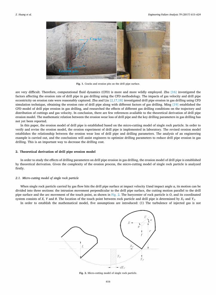
Gas drilling is a kind of under-balanced drilling technology using high-speed gas to carry cuttings to surface, which can improvethe production capacity of oil gas well significantly [1]. However, high-speed cuttings-carrying flow erodes drill pipe persistently,especially for drill pipe joint [2]. It is clearly observed from Fig. 1 that cracks and erosion pits present on the drill pipe surface in gasdrilling, easily causing drill pipe fracture and washout, or even personal casualty. The statistics show that the drill pipe would lose1–10 kg/m due to flow erosion in gas drilling. Just in 2014, erosion wear accidents account for 65% of the total failure accidents ofdill pipe in one gas field in China. Therefore, it has great practical value to study the erosion wear law, in order to reduce drill pipeerosion in gas drilling.
Several scholars have studied the erosion phenomena and erosion profile prediction [3–7]. Their findings suggest that the velocityof erosion particles, material properties and impact angle are the most important factors of erosion [8]. In addition, some erosionwear theories were proposed [9–12]. With the development of oil and gas industry, erosion wear of drill pipe has become the researchhotspot [13,14]. Wei [15] proposed a cuttings-carried theory and modified the critical cuttings-carried model for the gas-solid flow ingas drilling. Due to the complexity of the practical drilling conditions, the field and laboratory experiment studies of drill pipe erosion
http://dx.doi.org/10.1016/j.engfailanal.2017.05.023Received 30 September 2016; Received in revised form 28 April 2017; Accepted 3 May 2017
⁎ Corresponding author at: State Key Laboratory of Oil & Gas Reservoir Geology and Exploitation, Southwest Petroleum University, Chengdu, Sichuan 610500, PRChina.
E-mail address: [email protected] (Z. Huang).
Engineering Failure Analysis 79 (2017) 615–624
Available online 16 May 20171350-6307/ © 2017 Published by Elsevier Ltd.
MARK
are very difficult. Therefore, computational fluid dynamics (CFD) is more and more wildly employed. Zhu [16] investigated thefactors affecting the erosion rate of drill pipe in gas drilling using the CFD methodology. The impacts of gas velocity and drill pipeeccentricity on erosion rate were reasonably captured. Zhu and Liu [2,17,18] investigated drill pipe erosion in gas drilling using CFDsimulation technique, obtaining the erosion rate of drill pipe along with different factors of gas drilling. Ming [19] established theCFD model of drill pipe erosion in gas drilling, and researched the effects of different gas drilling conditions on the trajectory anddistribution of cuttings and gas velocity. In conclusion, there are few references available to the theoretical derivation of drill pipeerosion model. The mathematic relation between the erosion wear loss of drill pipe and the key drilling parameters in gas drilling hasnot yet been reported.
In this paper, the erosion model of drill pipe is established based on the micro-cutting model of single rock particle. In order toverify and revise the erosion model, the erosion experiment of drill pipe is implemented in laboratory. The revised erosion modelestablishes the relationship between the erosion wear loss of drill pipe and drilling parameters. The analysis of an engineeringexample is carried out, and the conclusions will assist engineers to optimize drilling parameters to reduce drill pipe erosion in gasdrilling. This is an important way to decrease the drilling cost.
2. Theoretical derivation of drill pipe erosion model
In order to study the effects of drilling parameters on drill pipe erosion in gas drilling, the erosion model of drill pipe is establishedby theoretical derivation. Given the complexity of the erosion process, the micro-cutting model of single rock particle is analyzedfirstly.
2.1. Micro-cutting model of single rock particle
When single rock particle carried by gas flow hits the drill pipe surface at impact velocity Uand impact angle α, its motion can bedivided into three sections: the intrusion movement perpendicular to the drill pipe surface, the cutting motion parallel to the drillpipe surface and the arc movement of the touch point, as shown in Fig. 2. The barycenter of rock particle is O, and its coordinatedsystem consists of X, Y and θ. The location of the touch point between rock particle and drill pipe is determined by XT and YT.
In order to establish the mathematical model, five assumptions are introduced: (1) The turbulence of injected gas is not
Fig. 1. Cracks and erosion pits on the drill pipe surface.
Fig. 2. Micro-cutting model of single rock particle.
Z. Huang et al. Engineering Failure Analysis 79 (2017) 615–624
616

considered. (2) The width of rock particle b remains unchanged. (3) The elastic deformation of drill pipe is ignored and its plastic flowstress is a constant. (4) The contact force between rock particle and drill pipe is focused on the cutting point, and the ratio of itshorizontal component Fx to vertical component Fv is a constant. (5) The ratio of contact surface height L to cutting depth YT keepsconstant. Therefore, two constants are introduced:
ψ LY
ζ FF
= , =T
x
y (1)
According to Newton's second law, when the rotating torque caused by the vertical contact force is neglected, the equations for amoving rock particle can be given by:
⎧⎨⎪
⎩⎪mY ψζbσYmX ψbσXIθ ψbσYr
¨ + = 0¨ + = 0
¨ + = 0 (2)
where m is the mass of rock particle. σ is the plastic flow stress of drill pipe material. I is the rotational inertia of rock particle about itsbarycenter. X , Y and θ are the horizontal, vertical and rotational acceleration of rock particle respectively. r is the distance from thebarycenter of rock particle to the cutting surface.
The initial boundary conditions of the rock particle movement can be expressed as:
⎧⎨⎪
⎩⎪Y Y U αX X U αθ θ θ
= 0 = sin= 0 = cos= 0 =
t t
t t
t t
=0 =0
=0 =0
=0 =0 0 (3)
Therefore, the solutions of Eq. (2) can be written as:
⎧
⎨⎪⎪
⎩⎪⎪
( )Y α βt
X βt U α t t β σ
θ U α βt βt θ t
= sin ⋅sin( )
= sin( ) + ( cos )⋅ − ⋅ =
= sin (sin( ) − ) +
Uβ
U αβζ
U αζ
ζψbm
mrβIζ
sin sin
0 (4)
where t is the cutting time, θ0 is the initial rotational speed of rock particle.If the impact angle α is smaller, the rock particle keeps the horizontal motion when it breaks away from the surface of drill pipe
(t= t0). Y=0 can be obtained at this moment.
βt βt πsin( ) = 0 or =c c (5)
However, if the impact angle α is larger, the rock particle has stopped the horizontal motion before it breaks away from thesurface of drill pipe due to excessive energy consumption:
X = 0T t t= c (6)
Because the rotation of rock particle is very small during the micro-cutting process, the horizontal displacement attached to thetouch point can be approximately represented by an arc:
X X rθ= +T (7)
If the initial rotational speed is ignored and I=mr2/2 is introduced, substituting Eqs. (4) and (7) into (6), one obtains therelational expression in the form:
βt ζα
cos( ) = 1 −3 tanc (8)
when α α= = arctan ζ0 6 is workable, sin(βtc)=0 or βtc=π can be derived.
In which α0 is the critical impact angle, which represents that the kinetic energy of rock particle disappears entirely at themoment.
According to the assumptions, the cutting volume w caused by single rock particle can be given by
⎜ ⎟⎛⎝
⎞⎠∫ ∫w b Y dX b Y d
dtX rθ dt= = ( + )
tT T
t
0 0
c c
(9)
α≤α0, according to Eqs. (6) and (9), can be obtained as follows:
⎛⎝⎜
⎞⎠⎟w mU
ψζσα
ζα= sin 2 − 6 sinI
22
α > α0, according to Eqs. (8) and (9), can be obtained as follows:
Z. Huang et al. Engineering Failure Analysis 79 (2017) 615–624
617

⎛⎝⎜
⎞⎠⎟w mU
ψζσ ζα= 6 cosII
22
Therefore, the cutting volume w is simply expressed as:
w mUψζσ
f α= ( )2
(10)
where
⎧⎨⎪⎩⎪
f αα α α α
α α α( ) =
sin 2 − sin ≤
cos >ζ
ζ
6 20
6 20
2.2. Erosion model of rock particles flow
Rock particles brought into annular space repeatedly impact drill pipe and borehole wall, causing erosion wear, as shown inFig. 3. Q represents the gas injection volume under standard state, d is the drill pipe diameter, Dc is the diameter of casing atcalculated point, Db is the drill bit diameter, h is ROP, l is the distance between the adjacent two collisions on drill pipe.
In order to simplify the mathematical model, four assumptions are necessary: (1) Impact angle α is a constant when gas injectionvolume Q and ROP h remain unchanged. (2) The collisions between drill pipe and rock particles are perfectly elastic. (3) Thecollisions among rock particles are ignored. (4) The velocity of rock particles U is consistent with gas flow rate v. So the area ofannular space at calculated point A will yield the following expression:
A π D d=4 ( − )c
2 2(11)
According to the classic formula for computing gas injection volume proposed by Angel in 1957, the gas flow rate v can beobtained [20].
v QTPA
= 5.763(12)
where P and T are the pressure and degree kelvin at the calculated point respectively.Combining Eqs. (4) and (5) yields
v QTP D d
= 7.338( − )c
2 2 (13)
The total mass of rock particles in annular space per unit time M is obtained by the geometric conditions and drilling conditions.
M π D hρ=4 b r
2(14)
where ρr is the average density of rock particles.
l
Q
dcD
Rock particle Annular space
Drill pipe Casing
Fig. 3. Erosion wear sketch map of rock particles flow.
Z. Huang et al. Engineering Failure Analysis 79 (2017) 615–624
618

The collision times between drill pipe and rock particles per unit length η can be given by:
ηl
αD d
= 1 = tan( − )c (15)
So the erosion wear mass of drill pipe per unit time and length W can be represented as:
W cηw Mm
ρ= d (16)
where c is the proportion of the rock particles doing the ideal cutting movement, ρd is the density of drill pipe steel.Combining Eqs. (10), (13), (14), (15) and (16) yields
W cQ T D h
ψζσ D d D d Pρ ρ f α= 42.29
( − ) ( + )( )b
c cr d
2 2 2
2 2 (17)
In order to analyze conveniently, two new state variables are defined.
kρ
ψζσk
cD ρ f αD d D d
=42.29
, =( )
( − ) ( + )d b r
c c1 2
2
2 (18)
where k1 represents the material properties of drill pipe, k2 reflects the parameters of borehole structure, and K=k1k2 is a constantfor a given oil and gas well.
In conclusion, Eq. (17) can be rewritten in the form:
⎜ ⎟⎛⎝
⎞⎠W K T
PQ h=
22
(19)
Eq. (19) is the mathematical expression of drill pipe erosion model, and it is also appropriate for calculating the erosion wear lossof casing. This model establishes the relationship between the erosion wear loss of drill pipe and drilling parameters.
3. Laboratory experiment
Because some assumptions are introduced during the process of the theoretical derivation above, the accuracy of the erosionmodel should be further verified and its critical constants have not been determined. Therefore, relevant laboratory experiment isconducted in this section.
3.1. Experiment apparatus
The experimental facility designed for drill pipe erosion by Southwest Petroleum University was employed in this experiment, asshown in Fig. 4. Its main technical parameters include that the gas injection volume of blower is 20–65 m3/min, the maximal exhaustpressure is 40 KPa, the inner diameter of experimental well bore is 206 mm, the external diameter of experimental drill pipe is127 mm, the length of experimental well section is 4000 mm, and the distance between drill pipe sample and the entry of well bore is3500 mm.
Fig. 4. Experimental apparatus for erosion wear in laboratory. 1-blower; 2-wind control valve; 3-flowmeter; 4-gas-cuting mixer; 5-accelerating tube; 6-feedingapparatus; 7-sand box; 8-observation section; 9-wellbore; 10-rotary motor; 11-cyclone separator; 12-water tank; 13-exhaust pipe; 14-control cabinet.
Z. Huang et al. Engineering Failure Analysis 79 (2017) 615–624
619

3.2. Experiment samples
Silica sands of average crystal size 1–2 mm were chosen as the rock particles, as shown in Fig. 5. Three drill pipe samples and fourdrill pipe joint samples were produced using S135 steel, and were mounted on the sample flumes circumferentially equispaced on thepipe surface and the windward slope of drill pipe, as shown in Fig. 6. The effective erosion area of single drill pipe joint sample anddrill pipe sample is 2487 mm2 and 5973 mm2, respectively.
3.3. Experiment design
The drilling parameters involved in this experiment were gas injection volume and ROP. Thereinto, the gas injection volumeincluded three levels, 20.53 m3/min, 40.95 m3/min and 61.48 m3/min, and ROP included six levels, 3.35 m/h, 10.05 m/h, 13.0 m/h,21.33 m/h, 27.15 m/h and 32.83 m/h. According to the borehole size, different levels of ROP were converted into the amount ofadding silica sand, 5.0 kg/min, 15.0 kg/min, 19.38 kg/min, 31.82 kg/min, 40.5 kg/min and 48.98 kg/min, respectively. Thegrouping scheme of this experiment is shown in Table 1.
The duration of each experiment was 10 h, and the weighing method was applied to obtain the mass loss of each drill pipe sample.
Fig. 5. The experimental silica sands. (a) before experiment; (b) after experiment.
Fig. 6. (a) Drill pipe joint samples, (b) drill pipe samples, and (c) sample flumes.
Table 1The grouping tabulation of the erosion wear experiment.
Gas injection volume Experimental grouping scheme design
Group number
20.53 m3/min 1 2 3 4 5 640.95 m3/min 7 8 9 10 11 1261.48 m3/min 13 14 15 16 17 18
ROP3.35 m/h 10.05 m/h 13.0 m/h 21.33 m/h 27.15 m/h 32.83 m/h
Z. Huang et al. Engineering Failure Analysis 79 (2017) 615–624
620

According to the average mass loss of three drill pipe samples and their dimensions, the mass loss of drill pipe in unit distance andtime was calculated to characterize its erosion wear loss in this paper.
4. Results and discussion
4.1. Erosion wear morphology analysis of samples
SEM images from morphology of the samples after erosion experiment are shown in Fig. 7. The erosion wear morphology of thedrill pipe sample is characterized by abundant grooving scratches and few impact dents because rock particles impact it at a smallimpact angle, which matches well with the micro-cutting model above. On the contrary, because the rock particles impact the drillpipe joint sample at a large impact angle, its erosion wear morphology is characterized by abundant impact dents and few groovingscratches. Because the joint part accounts for only a small proportion of the entire drill pipe, the rationality of using the micro-cuttingmodel to deduce the erosion model of drill pipe is verified.
4.2. Erosion wear loss of drill pipe
Fig. 8 shows the variation laws of the erosion wear loss of drill pipe with ROP under different gas injection volume. When gasinjection volume is constant, the erosion wear loss of drill pipe increases with the increase of ROP firstly, and then decreases as ROPcontinues to increase. When the ROP improves, the rock particles concentration increases in annular space. Under a certain gasinjection volume, increasing ROP is equivalent to reducing the average velocity of cuttings. When ROP reaches the threshold value,the erosion wear loss of dill pipe will be reduced. As can be seen from Fig. 8, the erosion wear loss of dill pipe reaches the maximumvalue when ROP is approximately 20 m/h.
Fig. 9 shows the erosion wear loss of drill pipe varying with gas injection volume under different ROP. When ROP is constant, theerosion wear loss of drill pipe monotonically increases with the increase of gas injection volume. However, the growth rate of erosionwear loss increases as ROP rises when ROP is slow (≤20 m/h), but reduces as ROP continues to increase when ROP exceeds a criticalvalue (> 20 m/h).
Through experimental data fitting, the critical constants of the erosion model are determined, and the mathematical model of drill
Fig. 7. SEM images of the samples after erosion experiment. (a) drill pipe; (b) drill pipe joint.
0 5 10 15 20 25 30 350
2
4
6
8
10
12
14
16
Ero
sion
wea
r lo
ss (
10-3
Kg/
m·h
)
ROP (m/h)
20.53 m3/min 40.95 m3/min 61.48 m3/min
Gas injection volume
Fig. 8. Effect of ROP on erosion wear loss of drill pipe.
Z. Huang et al. Engineering Failure Analysis 79 (2017) 615–624
621

pipe erosion wear can be revised as:
⎧⎨⎪⎩⎪
WQ h h
h h=
3.569( ) ⋅ × 10 ≤ 20
4.5454(11.376 ln( ) − 123.8353)⋅ × 10 > 20
TP
TQP
2 2.0307 0.5863 −14
−0.4702 −3(20)
Experiment results has not only verified the mathematical model of drill pipe erosion wear, but also revised it, which helps toforecast the erosion wear loss of drill pipe. It can be obtained that when ROP is less than 20 m/h, the erosion wear loss of drill pipe isapproximatively proportional to the square of gas injection volume and has positive correlation with ROP. However, when ROP isfaster than 20 m/h, the erosion wear loss has negative correlation with ROP.
4.3. Engineering calculation example analysis
During gas drilling, the main technical parameters include the gas injection volume 100–240 m3/min and ROP 0–30 m/h.According to the revised erosion model (Eq. (20)), the effect of gas injection volume and ROP on the erosion wear loss of drill pipe isobtained by MATLAB software, as shown in Fig. 10. It can be seen that gas injection volume has more impact on erosion wear losscompared to ROP, and high ROP will suppress the erosion wear of drill pipe. Therefore, under the conditions of meeting the cleaningand cooling requirements, the erosion wear loss of drill pipe can be reduced by using lower gas injection volume and higher ROP(20–30 m/h) in gas drilling, which can decrease the drilling cost effectively.
240
220
200
180
160
140
120
100
0.00
0.01
0.02
0.03
0.04
0.05
0.06
0.07
0.08
30
2520
1510
50
Ero
sion
wea
rlo
ss (
Kg/
m·h
)
ROP(m/h)
Gas injection volume (m 3/min)
Fig. 10. Effect of gas injection volume and ROP on erosion wear loss.
15 20 25 30 35 40 45 50 55 60 650
2
4
6
8
10
12
14
16
Ero
sion
wea
r lo
ss (
10-3K
g/m
·h)
Gas injection volume (m3/min)
3.35 m/h 10.05 m/h 13.0 m/h 21.33 m/h 27.15 m/h 32.83 m/h
ROP
Fig. 9. Effect of gas injection volume on erosion wear loss of drill pipe.
Z. Huang et al. Engineering Failure Analysis 79 (2017) 615–624
622

5. Conclusions
The analytical analysis and laboratory experiment are carried out in this paper to research the erosion wear law of drill pipe in gasdrilling. The present study and analysis enable the following conclusions to be drawn:
(1) The mathematical model of drill pipe erosion wear is derived based on the theoretical analysis, which establishes the relationbetween the erosion wear loss of drill pipe and drilling parameters, such as gas injection volume and ROP.
(2) The laboratory experiment is carried out to verify and revise the erosion model of drill pipe. When ROP is less than 20 m/h,the erosion wear loss of drill pipe is approximatively proportional to the square of gas injection volume and has positive correlationwith ROP. But it has negative correlation with ROP when ROP is faster than 20 m/h.
(3) Gas injection volume has more impact on drill pipe erosion compared with ROP, and high ROP will suppress the erosion wearof drill pipe. Under the conditions of meeting the drilling requirements, employing lower gas injection volume and higher ROP(20–30 m/h) can reduce the erosion wear loss of drill pipe in gas drilling.
Nomenclature
U the impact velocity of rock particle (m/s)α the impact angle of rock particle (°)X ,Y ,θ the coordinated system of the barycenter of rock particleXT ,YT the location of the touch point of rock particleb the width of rock particle (m)Fx the horizontal component of contact force (N)Fv the vertical component of contact force (N)L the height of contact surface (m)m the mass of rock particle (kg)σ the plastic flow stress of drill pipe material (Pa)r the distance from the barycenter of rock particle to the cutting surface (m)I the rotational inertia of rock particle about its barycenter (kg·m2)X Y θ , , the horizontal, vertical and rotational speed of rock particle (m/s, m/s, rad/s)X Y θ¨ , ¨, ¨ horizontal, vertical and rotational acceleration of rock particle (m/s2, m/s2, rad/s2)α0 critical impact angle (°)w the cutting volume of single rock particle (m3)Q gas injection volume (m3/min)h rate of penetration (ROP) (m/h)d drill pipe diameter (m)Dc the diameter of casing at calculated point (m)Db drill bit diameter (m)l the distance between the adjacent two collisions on drill pipe (m)v gas flow rate (m/s)A the area of annular space at calculated point (m2)P ,T the pressure and degree kelvin at the calculated point (MPa, K)M the total mass of rock particles in annular space per unit time (kg)η the collision times between drill pipe and rock particles per unit length (−)c the proportion of the rock particles doing the ideal cutting movement (−)ρr ,ρd the average density of rock particles and drill pipe steel (kg/m3)W the erosion wear mass of drill pipe per unit time and length (kg/m·h)
Acknowledgments
This work reported in this paper was supported by the Natural Science Foundation of China (No.: 51222406 and 51134004) andthe National 863 Plan of China (No.: 2012AA061201).
References
[1] W. Lyons, Air and Gas Drilling Manual, (2009).[2] S. Liu, H. Zheng, X. Zhu, Drill string failure analysis and erosion wear study at key point for gas drilling, Energy Explor. Exploit. 32 (3) (2014) 553–568.[3] J. Postlethwaite, U. Lotz, Mass transfer at erosion-corrosion roughened surfaces, Can. J. Chem. Eng. 66 (66) (1988) 75–78.[4] S. Uchida, M. Naitoh, H. Okada, Y. Uehara, S. Koshizuka, Evaluation of flow accelerated corrosion by coupled analysis of corrosion and flow dynamics.
Relationship of oxide film thickness, hematite magnetite ratio, ECP and wall thinning rate, Nucl. Eng. Des. 241 (11) (2011) 4585–4593.[5] G.R. Wang, F. Chu, S.Y. Tao, L. Jiang, H. Zhu, Optimization design for throttle valve of managed pressure drilling based on CFD erosion simulation and response
surface methodology, Wear s338-339 (5) (2015) 114–121.[6] R. Zhang, H. Liu, C. Zhao, A probability model for solid particle erosion in a straight pipe, Wear 308 (1–2) (2013) 1–9.[7] H. Liu, Z. Zhou, M. Liu, A probability model of predicting the sand erosion profile in elbows for gas flow, Wear s342-343 (2015) 377–390.[8] R.G. Wellman, C. Allen, The effects of angle of impact and material properties on the erosion rates of ceramics, Wear s186-187 (1995) 117–122.
Z. Huang et al. Engineering Failure Analysis 79 (2017) 615–624
623

[9] I.M. Hutchings, A model for the erosion of metals by spherical particles at normal incidence, Wear 70 (3) (1981) 269–281.[10] J.R. Zhou, S. Bahadur, Effect of blending of silicon carbide particles in varying sizes on the erosion of Ti-6Al-4V, Wear 132 (2) (1989) 235–246.[11] W. Tabakoff, V. Shanov, Erosion rate testing at high temperature for turbomachinery use, Surf. Coat. Technol. 76 (76) (1995) 75–80.[12] X. Huang, Q. Liu, An erosion model of drill string based on process parameters of gas drilling, Acta Pet. Sin. 33 (5) (2012) 878–880 (in Chinese).[13] B. Arefi, A. Settari, P. Angman, Analysis and simulation of erosion in drilling tools, Wear 259 (1–6) (2005) 263–270.[14] B. Arefi, A. Settari, P. Angman, Simulation of erosion in drilling tools for the oil and gas industry, J. Can. Pet. Technol. 45 (11) (2006) 87–96.[15] N. Wei, Y.F. Meng, G. Li, Y.J. Li, A.Q. Liu, J.X. Long, C.Y. Xin, S.B. Wen, Cuttings-carried theory and erosion rule in gas drilling horizontal well, Therm. Sci. 18 (5)
(2014) 1695–1698.[16] H. Zhu, Y. Lin, D. Zeng, Y. Zhou, J. Xie, Y. Wu, Numerical analysis of flow erosion on drill pipe in gas drilling, Eng. Fail. Anal. 22 (1) (2012) 83–91.[17] X. Zhu, LIU. A study on the drill pipe erosion law in gas drilling, Acta Pet. Sin. 31 (6) (2010) 1013–1017 (in Chinese).[18] X. Zhu, S. Liu, H. Tong, X. Huang, J. Li, Experimental and numerical study of drill pipe erosion wear in gas drilling, Eng. Fail. Anal. 26 (12) (2012) 370–380.[19] X. Ming, Z. Lian, T. Lin, X. Chen, J. Zheng, Study on the erosion law of gas with cuttings against tool joint, J. Southwest Pet. Univ. Sci. Technol. Ed. 36 (3) (2014)
173–178 (in Chinese).[20] G. Dong, J.Y. Zhang, Developments of research on the solid particle erosion of materials, Mater. Sci. Eng. 21 (2) (2003) 307–312 (in Chinese).
Z. Huang et al. Engineering Failure Analysis 79 (2017) 615–624
624

本文献由“学霸图书馆-文献云下载”收集自网络,仅供学习交流使用。
学霸图书馆(www.xuebalib.com)是一个“整合众多图书馆数据库资源,
提供一站式文献检索和下载服务”的24 小时在线不限IP
图书馆。
图书馆致力于便利、促进学习与科研,提供最强文献下载服务。
图书馆导航:
图书馆首页 文献云下载 图书馆入口 外文数据库大全 疑难文献辅助工具