ENGINEERING DATA TRANSMITTAL - Energy
22
ENGINEERING DATA TRANSMITTAL I. 823275f 2. To: (Receiving Organization) 3. From: (Originating Organization) 4. Related EDT No.: Distribution ARES Corporation N/A 5. Structure Location: _______________________________241 -AW 6. Proj./Prog./Dept./Div.: 7. Responsible Engineer/Design Agent: 8. System Designator: Waste Feed Delivery - Transfer Line Upgrades DE Legare/T Saizano WT 9. Building No.: ______________________________24 1-AW 10. Originator Remarks: 11. Equipment ID No. (EIN): Initial Release of RPP-RiPT-428 14, 241-A W Clean Out Boxes A W-3, A W-5, and A W- 7 Functions and N/A Requirements Evaluation Document 12. Penmit/Permit Application No.: _______________________N/A 13IJQo.T -O - 3'- DO [ON/A 13(A). TBDs or HOLDsIn the Data Transmitted? E0 Yes Z No 15. Purchase Order No.: Date: it 4101~ 13(B). Project Number or Identifier: N/A 14. PrHAScreeningNo.:01O'f{[] N/A NA 16. Required Response Date: 17. DATA TRANSMITTED (F) (G) (H) (I) QJ) (A) (C) (D) HErd- Approval Reason Origi- Receiv- Item (B) Sheet Rev. (E) copy Desig- for nator er No. Document/Drawing No. No. No. Title or Description of Data Transmitted or nator Trans- Dispo- Dispo- PDF mittal sition sition 1 RPP-RPT-42814 All 10 24 1-AW Clean Out Boxes AW-3, AW-5, and H ESQ 1 1 ___________________AW-7 Functions and Requirements Evaluation Document 18. IMPACTED DOCUMENTS - NON ENGINEERING 19. IMPACTED DOCUMENTS - ENGINEERING Type of Document Document Number Type of Document Document Number N/A N/A N/A N/A 20. KEY Apnroval Designator (Q) Reason for ransmittal (H) Disnosition (I) Se TC-NGDEIG-C25 1. Approval 3. Distribution 1.Approved 3. Reviewed no comment 5. Disapproved 2. Review 2. Approved w/comment 4. Reviewed w/comment 21. SIGNATURE/DISTRIBUTION (H) H Rea- (J) Name (K) Signature (L) Date (M) MSIN Rea -D (I) ) Name (K) Signature (L) Date (M) MSIN son Ds.son _____________________________ 1 Originator T Salzano ~ - t ~.~ ARES 1 Resp. Engr. DE Legare 1I Resp. Mgr. JX~ Kelly 16 .- ,1S7-67 1 ~fQATL Bennington jj '2 1 IH&S Engr.WvL Adams. / 3 0 51 1 Env. Engr. FR Miera J RI-51 22. DOE APPROVAL (if required) L 0-at Ctrl. No. w ~ ~ 2 C~ 23. Release Date/StationJID ( 4 __ _ __ __ ___ __ __ __ NOV 11209 3-~ -- BD-7400-172.2 (REV 2)
Transcript of ENGINEERING DATA TRANSMITTAL - Energy

ENGINEERING DATA TRANSMITTAL I. 823275f2. To: (Receiving Organization) 3. From: (Originating Organization) 4. Related EDT No.:Distribution ARES Corporation N/A
5. Structure Location:_______________________________241 -AW
6. Proj./Prog./Dept./Div.: 7. Responsible Engineer/Design Agent: 8. System Designator:Waste Feed Delivery - Transfer Line Upgrades DE Legare/T Saizano WT
9. Building No.:______________________________24 1-AW
10. Originator Remarks: 11. Equipment ID No. (EIN):Initial Release of RPP-RiPT-428 14, 241-A W Clean Out Boxes A W-3, A W-5, and A W- 7 Functions and N/ARequirements Evaluation Document 12. Penmit/Permit Application No.:
_______________________N/A
13IJQo.T -O - 3'- DO [ON/A 13(A). TBDs or HOLDsIn the Data Transmitted? E0 Yes Z No 15. Purchase Order No.:
Date: it 4101~ 13(B). Project Number or Identifier: N/A14. PrHAScreeningNo.:01O'f{[] N/A NA 16. Required Response Date:
17. DATA TRANSMITTED (F) (G) (H) (I) QJ)(A) (C) (D) HErd- Approval Reason Origi- Receiv-
Item (B) Sheet Rev. (E) copy Desig- for nator erNo. Document/Drawing No. No. No. Title or Description of Data Transmitted or nator Trans- Dispo- Dispo-
PDF mittal sition sition1 RPP-RPT-42814 All 10 24 1-AW Clean Out Boxes AW-3, AW-5, and H ESQ 1 1
___________________AW-7 Functions and Requirements Evaluation
Document
18. IMPACTED DOCUMENTS - NON ENGINEERING 19. IMPACTED DOCUMENTS - ENGINEERINGType of Document Document Number Type of Document Document Number
N/A N/A N/A N/A
20. KEYApnroval Designator (Q) Reason for ransmittal (H) Disnosition (I)
Se TC-NGDEIG-C25 1. Approval 3. Distribution 1.Approved 3. Reviewed no comment 5. Disapproved2. Review 2. Approved w/comment 4. Reviewed w/comment
21. SIGNATURE/DISTRIBUTION(H) H
Rea- (J) Name (K) Signature (L) Date (M) MSIN Rea -D (I) ) Name (K) Signature (L) Date (M) MSINson Ds.son _____________________________
1 Originator T Salzano ~ - t ~.~ ARES
1 Resp. Engr. DE Legare
1I Resp. Mgr. JX~ Kelly 16 .- ,1S7-671 ~fQATL Bennington jj '2
1 IH&S Engr.WvL Adams. / 3 0 51
1 Env. Engr. FR Miera J RI-51 22. DOE APPROVAL (if required)
L 0-at Ctrl. No.
w ~ ~ 2 C~ 23. Release Date/StationJID ( 4__ _ __ __ ___ __ __ __ NOV 11209 3-~ --
BD-7400-172.2 (REV 2)

RPP-RPT-42814, Rev. 0
241 -AW Clean Out Boxes AW-3, AW-5, and AW-7Functions and Requirements EvaluationDocument
Katie A. WhiteARES Corporation for Washington River Protection Solutions, LLCRichland, WA 99352U.S. Department of Energy Contract DE-AC27-08RV1 4800
EDT/ECN: EDT-823275 UC:Cost Center: Charge Code:B&R Code: Total Pages: 21
Key Words: 241-AW, Clean-Out Boxes,, COB, 242-A, AW-3, AW-5, AW-7
Abstract: The purpose of this report is to document evaluation of the 241-AW Clean-Out Boxes' primaryand secondary containment structure's ability to perform their safety function under the conditions andevents for which the safety functions are required.
TRADEMARK DISCLAIMER. Reference herein to any specific commercial product, process, or service by trade name,trademark, manufacturer, or otherwise, does not necessarily constitute or imply its endorsement, recommendation, orfavoning by the United States Government or any agency thereof or its contractors or subcontractors.
Reea~ -rvlDate Release Stamp
Approved For Public Release
A-6002-767 (REV 2)

RPP-RPT-428 14, Rev. 0
241-AW CLEAN OUT BOXES AW-3, AW-5, AND AW-7 FUNCTIONS ANDREQUIREMENTS EVALUATION DOCUMENT
October 2009
prepared by
ARES Corporation1100 Jadwin Avenue, Suite 400Richland, Washington 99352
(509) 946-3300
prepared for
Washington River Protection Solutions, LLC
2

RPP-RPT-428 14, Rev. 0
TABLE OF CONTENTS
1.0 PURPOSE............................................................................................ 5
2.0 APPROACH...................................................................................... 5
3.0 SCOPE ............................................................................................ 6
4.0 SAFETY FUNCTION .............................................................................. 7
5.0 SYSTEM DESCRIPTION.......................................................................... 75.1 Boundaries................................................................................... 95.2 Interfaces.................................................................................... 9
6.0 SYSTEM EVALUATION ........................................................................ 106.1 Functional/Performance Requirements .................................................... 106.2 Failure Mode Evaluations................................................................... 10
6.2.1 Failures Due to Structural Loading Conditions .................................. 106.2.2 Failures Due to Process Conditions (Normal Operations, Off-Normal
Operations, Accident Conditions) ................................................. 126.2.3 Failures Due to Environmental Conditions ....................................... 156.2.4 Other Failure Modes................................................................ 17
6.3 General Aging ............................................................................... 176.4 Supporting Systems ......................................................................... 17
6.4.1 Electrical Power..................................................................... 176.4.2 Compressed Air..................................................................... 176.4.3 Pressure Relief ...................................................................... 176.4.4 Temperature Control (HVAC)..................................................... 176.4.5 Freeze Protection ................................................................... 176.4.6 Cooling............................................................................... 186.4.7 Lubrication .......................................................................... 186.4.8 Filtration ............................................................................. 186.4.9 Water................................................................................. 186.4.10 Other ................................................................................ 18
7.0 CONTROLS..................................................................................... 187.1 Performance Criteria ........................................................................ 187.2 Functional Tests ............................................................................. 18
8.0 CRITICAL CHARACTERISTICS............................................................... 198.1 1" PipeCap ................................................................................. 19
8. 1.1 Cap Chemical and Physical Characteristics ...................................... 198.2 2" Pipe Cap Assembly ...................................................................... 19
8.2.1 Cap and Pipe Chemical Characteristics........................................... 198.2.2 Cap Assembly Pressure Boundary ................................................ 20
8.3 12" Pipe Cap Assembly..................................................................... 208.3.1 Cap and Pipe Chemical Characteristics........................................... 208.3.2 Cap Assembly Pressure Boundary ................................................ 20
9.0 REFERENCES................................................................................... 21
3

RPP-RPT-42814, Rev. 0
LIST OF FIGURES
Figure 5-1. Standard COB Configuration .............................................................. 8Figure 5-2. Post-Modification Configuration.......................................................... 8
LIST OF TERMS
Abbreviations and Acronyms
CGI Commercial Grade Item
CMTR Certified Material Test Report
COB Clean-Out Box
DOE U.S. Department of Energy
ECN Engineering Change Notice
EPRI Electric Power Research Institute
FRED Functions and Requirements Evaluation Document
QA Quality Assurance
RCRA Resource Conservation and Recovery Act of 1976SSC system, structures, and components
WRPS Washington River Protection Solutions, LLC
Units
OF degrees Fahrenheit
ft foot
psig pound-force per square inch gauge
4

RPP-RPT-42814, Rev. 0
1.0 PURPOSE
The purpose of this report is to document the evaluation of the ability of the modifications to the241-AW Clean-Out Boxes (COB) AW-3, AW-5, and AW-7 to perform their safety function(s)under those conditions and events for which the safety functions are required.
Compliance with the critical characteristics and controls identified in this Functions andRequirements Evaluation Document (FRED) shall be verified and documented. Acceptablemeans of verification can be accomplished by one or more of the following means:
*Testing,*Evaluation,*Inspection,*Code compliance,*Procurement from a qualified supplier,*Certificate of Compliance or material certification,*Commercial Grade Itemn (CGI) Dedication,
* Independent Qualified Registered Professional Engineer review and approval, or" Nonconformance Report Disposition.
Documented evidence of compliance shall be identified in the Safety Equipment List.
2.0 APPROACH
Normal, accident, and off-normal operating conditions, environmental/climatic events, andpotential failures were considered for the 241-AW COBs AW-3, AW-5, and AW-7 modificationevaluation following U.S. Department of Energy (DOE) safety orders and guidance. Theexisting tank farm Safety Basis, combined with directly relevant and applicable waste transferline experience within tank farms operating history, were considered and utilized to their fullvalue and extent to support completion of the 241 -AW COB modifications FRED. The system,structures, and components (SSC) safety function (i.e., prevent or mitigate accidents) isdeveloped through the iterative hazard/accident analysis and safety controlsdevelopment/evaluation processes conducted at specified stages of, and in parallel with, thedesign process.
Safety functional requirements are developed by identifying SSC performance requirementsnecessary to accomplish the safety function. Some of these requirements may be developedduring hazard and accident analysis, while others may be developed through engineeringevaluation. Still others may be developed through a Process Hazard Analysis and evaluation ofconditions (modes) that could cause SSC failure.
The following sections of this report document the results of the processes and activitiesdescribed above which led to the definition of the 241-AW COB modifications' safety functionalrequirements, safety performance criteria, and key design aspects and critical characteristicsnecessary for the waste transfer pipes the COBs are associated with to perform their safety
5

RPP-RPT-42814, Rev. 0
function. This report also includes summaries of information discussed relative to the wastetransfer piping operability in normal and off-normnal operating conditions, and during applicableenvironmental and climatic events.
3.0 SCOPE
The scope of this report includes the following information with respect to the 241 -AW COBsAW-3, AW-5, and AW-7 modifications.
1. Documentation of safety SSC functional and performance requirements necessary forsafety SSCs to perform their intended safety functions. The safety SSC functionaland performance requirements were identified from design requirements, engineeringevaluation and calculations, the iterative hazard/accident analysis safety controlsdevelopment/evaluation process, and Process Hazard Analysis.
2. Documentation of key design aspects and safety SSC critical characteristics necessaryfor safety SSCs to perform their intended safety functions and identification of howthe key design aspects and safety SSC critical characteristics can be verified to bemet. Critical characteristics documented in this report's appendices are used in theCGI dedication process to establish a subset of component-specific criticalcharacteristics for use in CGI dedication to provide reasonable assurance the safetySSC is acceptable and will perform its safety-related function.
3. Documentation of additional safety SSC design and operability requirements, notdirectly associated with the credited safety SSC safety function; and discussion as tohow these additional requirements are met. These requirements fall into two generalcategories and can be defined generically as follows:
a. Design - Safety SSCs must be designed to reliably perform their safety functionunder those conditions and events for which their safety function is intended.
b. Environmental - Environmental conditions (e.g., natural phenomena, flooding,etc.) must be considered to ensure that safety SSCs can perform their safetyfunctions, as determined by the safety analysis, under postulated serviceconditions.
4. A summary of waste transfer line control development/evaluation discussions whichprovide background for the basis for selected safety SSCs.
In addition to the process approach described in Section 2.0 (DOE safety orders and guidance),the development/evaluation process used to derive the key design aspects and safety-SSC criticalcharacteristics documented in this report followed an approach similar to Electric PowerResearch Institute (EPRI) NP-5652, Guideline for the Utilization of Commercial Grade Items inNuclear Safety Related Applications , and EPRI TR-102260, Supplemental Guidance for theApplication of EPRI Report NP-5652 on the Utilization of Commercial Grade Items, forperforming and documenting technical evaluations. This approach helps ensure CGIs willperform their required safety functions. Subsequent CGI dedication training and mentoring
6

RPP-RPT-428 14, Rev. 0
provided by the Sequoia Consulting Group has been used as a method to validate engineeringjudgment used in selecting acceptable safety-SSC critical characteristics documented in thisreport and the corresponding CGI documentation.
This report documents the evaluation of the 241-AW COBs AW-3, AW-5, and AW-7modifications' safety functions.
4.0 SAFETY FUNCTION
Primary waste transfer piping systems are identified as safety-significant SSCs per the pendingamendment 45 in Engineering Change Notice (ECN)-725337-RO, Safety -Signi~ficant Designationof Tank Farm Waste Transfer Primary Piping Systems. Secondary encasements are referencedin ECN-725337-RO as underground piping equipment for pip-in-pipe designs. The safetyfunction of the waste transfer lines is defined as listed below.
1 . The identified safety function of the waste transfer primary piping system is toprovide confinement of waste; thus, decreasing the frequency of a waste transfer leakaccident.
2. The secondary encasement piping is to provide encasement to the primary pipingsystem in the case of a failed pipe to collect leaks and deliver them to a detectionpoint. The secondary encasement provides better leak confinement than otherconfigurations as it can be leak tested for integrity.
5.0 SYSTEM DESCRIPTION
Certain waste transfer lines installed between the 242-A Evaporator and 241 -AW Tank Farmwere equipped with COBs. COBs provided access to the slurry and supemate lines to facilitateclearing piping plugs encountered during normal operating conditions. The COBs are notcompliant with the Resource Conservation and Recovery Act of 1976 (RCRA). To use the wastetransfer lines equipped with COBs, the COBs must be removed in such a way as to leave thewaste transfer piping compliant with RCRA.
Figure 5-1 shows the typical COB configuration on the waste transfer lines between the 242-AEvaporator and 241 -AW Tank Farm.
The modifications to the COBs necessary to make the associated waste transfer lines RCRA-compliant involve disconnecting the two waste transfer lines and removing the surface portionsof the COBs. The planned modifications are shown in Figure 5-2.
7
RPP-RPT-42814, Rev. 0
Figure 5-1. Standard COB Configuration.
0-)
0s-O ~ t0Ml
(20)(2-0 [M)I4OCI
r- Tj11 7 fl' I r-,-,,
050-M4' 4'' e.0-2w/ -M25 W' 2bd-MO
VOLMOOMV'AbcMn
~ ~3SECIN SECTIO
Figure 5-2. Post-Modification Configuration.
3. THR INSULATION *PIPE CAP. 12* SCHEID 40 (SEE NOTE 7 ONPIPE CAP. 2" SCHIED 40 ASTM A234 OR APR H-2-70418 SH 1)ASTIM A234 OR WPB W/ 12" PIPE SCHED 40 x 6' LOW/ 2"APIPE,' SCHED 40, 0 4'LG ASTR A106 CR 8 [OTE]-,ASTR 4108 ORB
OPTIONAL I'PIPE CLOSURE #T.SHEET 9
IN-PROCESS OPTIONAL I"PIPE CLOSURE J COSRE ELCLOSURE WELD SCELOSSEE ELOTDSEE GEN NOTE 0 HE EGNNT
CLOSURE WELD IN-PROCESSEE SEN NOTE 0 CLOSURE WELD
SEE GEN NOTE 0
CAP 1 "SN-M25 & 2 ENC-M26a-FINAL CONDITION
CAP (2) 1"SL-M25 & 12"ENC-M26aFINAL CONDITION

RPP-RPT-42814, Rev. 0
Once the COB modifications are complete, the following components will serve the safetyfunctions identified in Section 4.0:
* 1 -inch socket weld caps,
* 2-inch pipe cap with pipe spool, and
* 12-inch pipe cap with pipe spool.
The 1 -inch pipe caps complete the primary pipe confinement/pressure boundary. The wastetransfer lines installed between 242-A and 241-AW were designed to accommodate a wastepressure of 400 psig. The 1 -inch pipe caps must be capable of meeting or exceeding the originaldesign pressure of 400 psig.
The 2-inch pipe cap with pipe spool and 12-inch pipe cap with pipe spool complete thesecondary or encasement pipe confinement/pressure boundary. The waste transfer lineencasements installed between 242-A and 241 -AW were designed to accommodate a leakedwaste pressure of 60 psig. The pipe cap and spool assemblies must be capable of meeting orexceeding the original design pressure of 60 psig.
The modifications to the COBs and waste transfer lines and the associated required tests arecompliant with ASME B31.3.
5.1 BOUNDARIES
Per ECN-725337-RO, the boundaries of the waste transfer piping system encompass all pipingand piping connections and components to the waste tank riser. Based on this boundarydetermination, the following components will serve the safety functions identified in Section 4.0once the modifications are complete:
* 1 -inch socket weld caps,
* 2-inch pipe cap with pipe spool, and
* 12-inch pipe cap with pipe spool.
The 1 -inch pipe caps complete the primary pipe confinement/pressure boundary. The 2-inchpipe cap with pipe spool and 12-inch pipe cap with pipe spool complete the secondary or
* encasement pipe confinement/pressure boundary. The modifications to the COBs and wastetransfer lines and the associated required tests are compliant with ASME B3 1.3.
5.2 INTERFACES
There are no interfaces between the COB modification components and other safety designatedSSCs other than the interface with the components being modified. The COB modificationinterfaces include SN-219 and SL- 168, the heat trace system, and the leak detection system. The
9

RPP-RPT-42814, Rev. 0
leak detection modification removes the existing COB AW-3 leak detector and does not involvethe installation of new leak detection equipment. The operability of the leak detection systemwill be verified by completion of functional tests of the remaining leak detection devices. Theleak detection system will not be further discussed in this FRED.
6.0 SYSTEM EVALUATION
This evaluation focuses only on the 1 -inch socket weld caps, 2-inch pipe cap assemblies, and the12-inch pipe cap assemblies. Associated equipment required to complete the waste transferpiping system, e.g., welding rod, heat trace, and insulation, are not discussed.
6.1 FUNCTIONAL/PERFORMANCE REQUIREMENTS
Per ECN-725337-RO, the waste transfer piping system is functionally required to maintainstructural integrity for waste transfer system conditions (e.g., pressure, temperature, wastecharacteristics).
6.2 FAILURE MODE EVALUATIONS
The following failure mechanisms have been identified for the waste transfer piping.
1. Chemical incompatibility with the waste stream such that the piping is eitherdamaged or corroded;
2. Piping components are not as represented (e.g., not per ASTM standards) such thatthe strength of the material is not appropriate; and
3. Piping assembly welds are not complete or of sufficient strength to maintainconfinement.
Additional mechanisms that may result in failure of the waste transfer piping components arereviewed in the following sections to evaluate if additional failure mechanisms exist.
6.2.1 Failures Due to Structural Loading Conditions
6.2.1.1. Dead Load (Weight of All Permanent Materials and Equipment)
The waste transfer piping components are located underground; therefore, the only dead load thepiping system would be subjected to is the compressive force of the earth material directly abovethe pipelines. As the modifications being made are consistent with the original design of thewaste transfer piping and consider the requirements of ASME B3 1.3 for piping modificationsand design, there is no indication that the components will be subjected to stresses beyond thatidentified in ASME B31.3.
10

RPP-RPT-428 14, Rev. 0
6.2.1.2. Snow Loads
The modifications to the waste transfer lines do not affect the system's ability to withstand snowloads.
6.2.1.3. Wind Loads
The waste transfer lines are located underground. As a result, the pipelines are not subjected towind loads.
6.2.1.4. Earthquake Loads
The modifications to the waste transfer lines do not affect the system's ability to withstandearthquake load.
6.2.1.5. Ash Fail Loads
The modifications to the waste transfer lines do not affect the system's ability to withstand ashfall loads.
6.2.1.6. Earth and Groundwater Pressures
The modifications to the waste transfer lines do not affect the system's ability to withstand earthand groundwater pressures.
6.2.1.7. Thermal Forces (Stresses and Movements Resulting from Variations inTemperature)
The waste transfer lines are located underground and therefore the variation in temperaturesexperienced by the system is muted. The modifications to the waste transfer lines do not affectthe system's ability to withstand thermal forces.
6.2.1.8. Creep and Shrinkage Loads (for Concrete Structures and Masonry)
It is not required to evaluate a failure method related to creep and shrinkage loads as thecomponents are not concrete structures or masonry.
6.2.1.9. Hose-Whip
The waste transfer piping is underground and is therefore not subjected to hose-whip loading.
6.2.1.10. Vehicle Traffic
The modifications to the waste transfer lines do not affect the system's ability to withstandvehicle traffic.

RPP-RPT-428 14, Rev. 0
6.2.1.11. Vehicle Collision
Once the modifications are completed, there will be no portions of the waste transfer pipingabove grade and therefore the waste transfer piping is not subjected to vehicle collision.
6.2.1.12. Load Drop or Impact (Load Handling Accident)
Once the modifications are completed, there will be no portions of the waste transfer pipingabove grade and therefore the waste transfer piping is not subject to load drop or impact failures.
6.2.1.13. Undermining from Failed Water Hoses
Although significant undermining would be required to compromise the waste transfer piping,undermining of the waste transfer lines due to failed water hoses should be apparent, allowingpiping repairs as necessary prior to the next waste transfer.
6.2.1.14. Blast Effects/Missiles from PropanefLPG Tank Explosions
Once the modifications are completed, there will be no portions of the waste transfer pipingabove grade and therefore the waste transfer piping is not subject to blast effects or missiles.
6.2.1.15. Impact/Damage from Excavation Activities
Excavation activities that compromise the waste transfer piping would be apparent, allowingshutdown of any ongoing transfers and allowing piping repairs as necessary prior to the nextwaste transfer.
6.2.2 Failures Due to Process Conditions (Normal Operations, Off-Normal Operations,Accident Conditions)
6.2.2.1. Process Pressure/Vacuum (Normal, Off-Normal)
The modifications being made are consistent with the original design of the waste transfer pipingand consider the requirements of ASME B3 1.3 for piping modifications and design. The wastetransfer piping's ability to withstand process pressure/vacuum is not affected by themodifications.
6.2.2.2. Process Temperature (Low)
The modifications being made are consistent with the original design of the waste transfer pipingand consider the requirements of ASME B3 1.3 for piping modifications and design. The wastetransfer piping's ability to withstand process temperature variations is not affected by themodifications.
12

R-PP-RPT-428 14, Rev. 0
6.2.2.3. Process Temperature (High)
The modifications being made are consistent with the original design of the waste transfer pipingand consider the requirements of ASME B3 1.3 for piping modifications and design. The wastetransfer piping's ability to withstand process temperature variations is not affected by themodifications.
6.2.2.4. Process chemistry (chemical attack by waste, headspace vapors, etc.)
The modifications being made are consistent with the original design of the waste transfer pipingand consider the requirements of ASME B31.3 for piping modifications and design. The wastetransfer piping's ability to withstand process chemistry variations is not affected by themodifications.
6.2.2.5. Fluid Expansion Effects (e.g., Thermal)
The modifications being made are consistent with the original design of the waste transfer pipingand consider the requirements of ASME B3 1.3 for piping modifications and design. The wastetransfer piping's ability to withstand process fluid expansion effects is not affected by themodifications.
6.2.2.6. Erosion
The modifications being made are consistent with the original design of the waste transfer pipingand consider the requirements of ASME B31.3 for piping modifications and design. The wastetransfer piping's ability to withstand erosion is not affected by the modifications.
6.2.2.7. Corrosion
The modifications being made are consistent with the original design of the waste transfer pipingand consider the requirements of ASME B3 1.3 for piping modifications and design. The wastetransfer piping's ability to withstand corrosion is not affected by the modifications.
6.2.2.8. Radiation Fields
The modifications being made are consistent with the original design of the waste transfer pipingand consider the requirements of ASME B3 1.3 for piping modifications and design. The wastetransfer piping's ability to withstand radiation fields is not affected by the modifications.
6.2.2.9. Plugging by Waste
The modifications being made are consistent with the original design of the waste transfer pipingand consider the requirements of ASME B3 1.3 for piping modifications and design. The wastetransfer piping is not subject to increased plugging as a result of the modifications.
13
RPP-RPT-428 14, Rev. 0
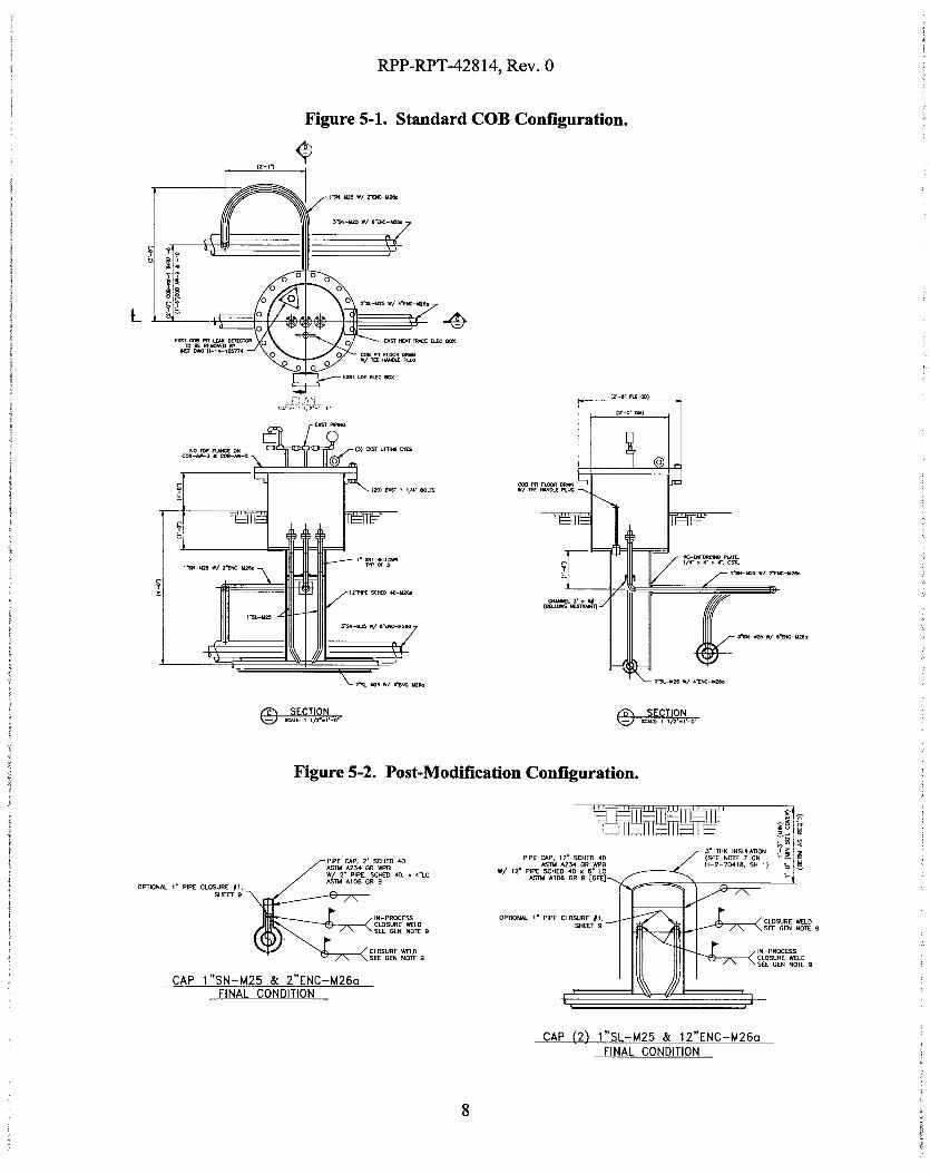
6.2.2.10. Plugged Filters (High Delta Pressure)
The waste transfer piping does not contain filters; therefore, the piping is not subjected toplugged filters.
6.2.2.11. Flammable Gas DeflagrationlDetonations Within Process Equipment
The modifications being made are consistent with the original design of the waste transfer pipingand consider the requirements of ASME B31.3 for piping modifications and design. The wastetransfer piping's ability to withstand flammable gas deflagrations/detonations is not affected bythe modifications.
6.2.2.12. Others
6.2.2.12.1. Hose Connections, Mid-point Primary Fittings Connections
The waste transfer piping is located below ground and is not in the vicinity of hose connections;therefore, the components would not fail as a result of the hose connections.
6.2.2.12.2. Chemical Spill
The modifications being made are consistent with the original design of the waste transfer pipingand consider the requirements of ASME B3 1.3 for piping modifications and design. The wastetransfer piping's ability to withstand chemnical spills is not affected by the modifications.
6.2.2.12.3. Fire
The modifications being made are consistent with the original design of the waste transfer pipingand consider the requirements of ASME B3 1.3 for piping modifications and design. The wastetransfer piping's ability to withstand fires is not affected by the modifications.
6.2.2.12.4. Over Pressure due to Failure in Compressed Air System Used to Blowout Hose-in-Hose Transfer Lines
The waste transfer piping would only be subjected to over pressure due to compressed air systemfailure associated with the Hose-in-Hose Transfer Lines if the air was routed incorrectly to thewaste transfer piping. The modifications being made are consistent with the original design ofthe waste transfer piping and consider the requirements of ASME B3 1.3 for piping modificationsand design. The waste transfer piping's ability to withstand excessive pressure is not affected bythe modifications.
14

RPP-RPT-428 14, Rev. 0
6.2.2.12.5. Organic Layer
The modifications being made are consistent with the original design of the waste transfer pipingand consider the requirements of ASME B3 1.3 for piping modifications and design. The wastetransfer piping's ability to withstand an organic layer is not affected by the modifications.
6.2.3 Failures Due to Environmental Conditions
6.2.3.1. Temperature - Low
The modifications being made are consistent with the original design of the waste transfer pipingand consider the requirements of ASME B3 1.3 for piping modifications and design. The wastetransfer piping's ability to withstand low temperatures is not affected by the modifications.
6.2.3.2. Temperature - High
The modifications being made are consistent with the original design of the waste transfer pipingand consider the requirements of ASME B3 1.3 for piping modifications and design. The wastetransfer piping's ability to withstand high temperatures is not affected by the modifications.
6.2.3.3. Thunderstorms, Dust, and Glaze
The waste transfer system affect by the COB modifications is located underground and istherefore not subjected to thunderstorms, dust, or glaze.
6.2.3.4. Solar Radiation (e.g., direct affects/damage due to exposure to UV)
The waste transfer system affect by the COB modifications is located underground and istherefore not subjected to exposure to ultra violet radiation.
6.2.3.5. Atmospheric Pressure
The modifications being made are consistent with the original design of the waste transfer pipingand consider the requirements of ASME B3 1.3 for piping modifications and design. The wastetransfer piping's ability to withstand atmospheric pressure variations is not affected by themodifications.
6.2.3.6. Ash (Exposure to Ash Particles)
The waste transfer system affect by the COB modifications is located underground and istherefore not subjected to exposure to ash particles.
15
RPP-RPT-42814, Rev. 0
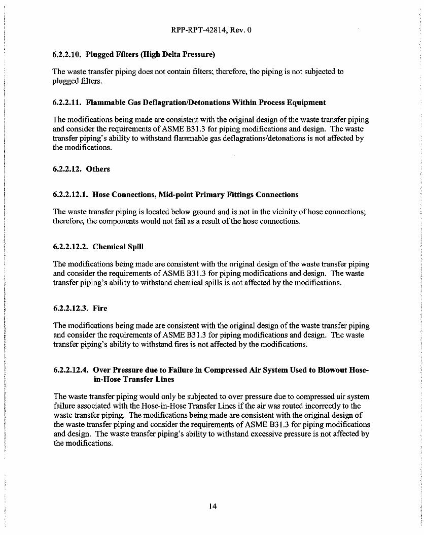
6.2.3.7. Exposure to Water (e.g., humidity/condensation, precipitation, flooding by servicewater)
The modifications being made are consistent with the original design of the waste transfer pipingand consider the requirements of ASME B3 1.3 for piping modifications and design. The wastetransfer piping's ability to withstand exposure to water is not affected by the modifications.
6.2.3.8. Exposure to Leaked Fluids Other than Water (e.g., hydraulic fluid)
The waste transfer lines are underground. If a sufficient volume of fluid was leaked, it ispossible it could reach the underground waste transfer piping. The modifications being made areconsistent with the original design of the waste transfer piping and consider the requirements ofASME B3 1.3 for piping modifications and design. The waste transfer piping's ability towithstand exposure to leaked fluids other than water is not affected by the modifications.
6.2.3.9. Exposure to/Submergence in Leaked Waste
The waste transfer lines were designed to transport waste. There are no impacts associated withexposure to leaked waste.
6.2.3.10. Fires (e.g., range fires, vehicle fires, refueling activity fires, other fires)
The modifications being made are consistent with the original design of the waste transfer pipingand consider the requirements of ASME B3 1.3 for piping modifications and design. The wastetransfer piping's ability to withstand exposure to fires is not affected by the modifications.
6.2.3.11. High Radiation Fields
The modifications being made are consistent with the original design of the waste transfer pipingand consider the requirements of ASME B3 1.3 for piping modifications and design. The wastetransfer piping's ability to withstand high radiation fields is not affected by the modifications.
6.2.3.12. Flammable Gas Deflagrations in Enclosures
The waste transfer lines are located below grade, not in an enclosure, and therefore are notsubjected to flammable gas deflagrations in enclosures.
6.2.3.13. Mechanical Abrasions
The modifications being made are consistent with the original design of the waste transfer pipingand consider the requirements of ASME B31.3 for piping modifications and design. The wastetransfer piping's ability to withstand mechanical abrasions is not affected by the modifications.
16

RPP-RPT-42814, Rev. 0
6.2.4 Other Failure Modes
Other failure modes that may impact the functionality of the waste transfer piping are notapparent.
6.3 GENERAL AGING
Waste transfer piping is not generally considered susceptible to aging, but is susceptible tocorrosion. The modifications being made are consistent with the original design of the wastetransfer piping and consider the requirements of ASME B3 1.3 for piping modifications anddesign. The waste transfer piping modifications will not increase the aging effects of the pipingor be more susceptible to aging than the original piping.
6.4 SUPPORTING SYSTEMS
6.4.1 Electrical Power
Not applicable. Electrical power is not required for the waste transfer lines to perform theirsafety function.
6.4.2 Compressed Air
Not applicable. Compressed air is not required for the waste transfer lines to perform their safetyfunction.
6.4.3 Pressure Relief
Not applicable. Pressure relief is not required for the waste transfer lines to perform their safetyfunction.
6.4.4 Temperature Control (HYAC)
Not applicable. Temperature controls are not required for the waste transfer lines to performtheir safety function.
6.4.5 Freeze Protection
The waste transfer lines are located below grade and will not be subjected to freezingtemperatures during waste transfer events. As a result, freeze protection is not required for thecomponents to perform their safety function.
17

RPP-RPT-428 14, Rev. 0
6.4.6 Cooling
Not applicable. Cooling (e.g., cooling water) is not required for the waste transfer piping toperform its safety function.
6.4.7 Lubrication
Not applicable. Lubrication is not required for the waste transfer piping to perform its safetyfunction.
6.4.8 Filtration
Not applicable. Filtration is not required for the waste transfer piping to perform its safetyfunction.
6.4.9 Water
Not applicable. Water is not required for the waste transfer piping to perform its safety function.
6.4.10 Other
There are no other supporting systems required for the waste transfer piping to perform its safetyfunction.
7.0 CONTROLS
7.1 PERFORMANCE CRITERIA
The performance criterion for the waste transfer piping is the same as the functional requirementof the piping: maintain structural integrity. The safety function of the waste transfer pipingsystem is ensured by designing, fabricating, testing, and inspecting the piping to ASME B3 1.3.
7.2 FUNCTIONAL TESTS
Operability of the waste transfer piping system is ensured though the implementation of ASMEB31.3. Testing is performed to verify the welds associated with the modifications are intact andhave sufficient structural strength to maintain structural integrity. Testing is also performed onthe components to ensure that they are consistent dimensionally and chemically with the ASTMstandards required by ASME B3 1.3
18
RPP-RPT-428 14, Rev. 0
8.0 CRITICAL CHARACTERISTICS
This document addresses only critical characteristics directly traceable to component safetyfunctions. The following sections identify preferred method(s) of verifying criticalcharacteristics of safety SSCs for use in the CGI process. However, at the time of verification,alternate but equivalent methods best suited to the situation may be identified, used, anddocumented. In addition, critical characteristics not directly related to the component's safetyfunction may be specified on the CGI dedication form in order to support reasonable assurancethat the CGI received matches the item specified. These additional specifications may include,but are not limited to, documentation and additional physical characteristics of the components(i.e., markings, dimensional checks, etc.). CGI dedication is not required for safety SSCsprocured from an evaluated supplier.
8.1 1" PIPE CAP
8.1.1 Cap Chemical and Physical Characteristics
The pipe cap must be comprised of ASTM A105 carbon steel.
1. Critical Characteristics
a. The pipe cap must be ASTM A105 carbon steel.
2. How Critical Characteristic is Verified to be Met
a. The determination of ASIM A105 carbon steel is verified by confirmation of thepresence of acceptable Certified Material Testing Reports (CMTRs) by WRPSQuality Assurance (QA).
8.2 2"1 PIPE CAP ASSEMBLY
8.2.1 Cap and Pipe Chemical Characteristics
The pipe cap must be comprised of ASTM A234 carbon steel. The pipe must be comprised ofASTM A106 carbon steel. If the socket weld cap is used, the coupling must be comprised ofASTM A105 carbon steel.
1. Critical Characteristics
a. The pipe cap must be ASTM A234 carbon steel.
b. The pipe spool must be ASTM A106 carbon steel.
c. If the socket weld cap is used, the coupling must be ASTM A105 carbon steel.
19

RPP-RPT-42814, Rev. 0
2. How Critical Characteristic is Verified to be Met
a. The determination of ASTM standard compliance is verified by confirmation ofthe presence of acceptable CMTR by WRPS QA.
8.2.2 Cap Assembly Pressure Boundary
The cap assembly must demonstrate structural integrity during a hydrostatic test at 90 psig inaccordance with the requirements of ASME B331.3.
1. Critical Characteristics
a. The cap assembly must demonstrate structural integrity during a hydrostatic testat 90 psig.
2. How Critical Characteristic is Verified to be Met
a. The presence of acceptable hydrostatic test result reports documenting thedemonstration of structural integrity during a hydrostatic test at 90 psig byWRPS QA.
8.3 12" PIPE CAP ASSEMBLY
8.3.1 Cap and Pipe Chemical Characteristics
The pipe cap must be comprised of ASTM A234 carbon steel. The pipe must be comprised ofASTM A 106 carbon steel.
1. Critical Characteristics
a. The pipe cap must be ASTM A234 carbon steel.
b. The pipe spool must be ASTM A106 carbon steel.
2. How Critical Characteristic is Verified to be Met
a. The determination of ASTM standard compliance is verified by confirmation ofthe presence of acceptable CMTRs by WRPS QA.
8.3.2 Cap Assembly Pressure Boundary
The cap assembly must demonstrate structural integrity during a hydrostatic test at 90 psig inaccordance with the requirements of ASME B3 1.3.
20

RPP-RPT-428 14, Rev. 0
1. Critical Characteristics
a. The cap assembly must demonstrate structural integrity during a hydrostatic test
at 90 psig.
2. How Critical Characteristic is Verified to be Met
a. The presence of acceptable hydrostatic test results reports documenting thedemonstration of structural integrity during a hydrostatic test at 90 psig byWRPS QA.
9.0 REFERENCES
ASME B31.3, Process Piping, American Society of Mechanical Engineers, New York,New York.
ASTM A 105, Standard Specification for Carbon Steel Forgings for Piping Applications, ASTMInternational, West Conshohocken, Pennsylvania.
ASTM Al 06, Standard Specification for Seamless Carbon Steel Pipe for High-TemperatureService, ASTM International, West Conshohocken, Pennsylvania.
AS TM A2 34, Standard Spec~f cation for Piping Fittings of Wro ugh t Carbon Steel and A lloySteel for Moderate and High Temperature Service, ASTM International,West Conshohocken, Pennsylvania.
ECN-725337-RO, 2009, Safety-Signifi2cant Designation of Tank Farm Waste Transfer PrimaryPiping Systems, Washington River Protection Solutions, Richland, Washington.
EPRI NP-5652, 1988, Guideline for the Utilization of Commercial Grade Items in NuclearSafety Related Applications, Electric Power Research Institute, Charlotte, North Carolina.
EPRI TR- 102260, 1994, Supplemental Guidance for the Application of EPRI Report NP-S5652 onthe Utilization of Commercial Grade Items, Electric Power Research Institute, Charlotte,North Carolina.
RPP-13033, 2009, Tank Farms Documented Safety Analysis (DSA), Rev 3-E, Washington RiverProtection Solutions, LLC, Richland, Washington.
TFC-ENG-STD-02, "Environmental/Seasonal Requirements for TOC Systems, Structures, andComponents," Rev A-4, Washington River Protection Solutions, LLC, Richland,Washington.
TFC-ENG-STD-06, "Design Loads for Tank Farm Facilities," Rev C-2, Washington RiverProtection Solutions, LLC, Richland, Washington.
21