Engineering Analysis of Furnace Stave with ANSYS Metal Stave Analysis ANSYS...Engineering Analysis...
67
Engineering Analysis of Furnace Stave with ANSYS Patented UltraLife ® Stave Property of Berry Metal Company – Confidential and Proprietary
Transcript of Engineering Analysis of Furnace Stave with ANSYS Metal Stave Analysis ANSYS...Engineering Analysis...
Engineering Analysis of Furnace Stave with ANSYSPatented UltraLife® Stave
Property of Berry Metal Company – Confidential and Proprietary
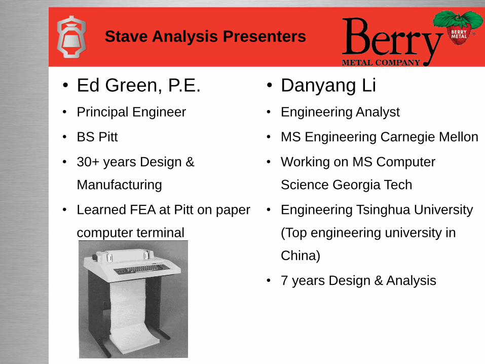
Stave Analysis Presenters
• Ed Green, P.E.
• Principal Engineer
• BS Pitt
• 30+ years Design &
Manufacturing
• Learned FEA at Pitt on paper
computer terminal
• Danyang Li
• Engineering Analyst
• MS Engineering Carnegie Mellon
• Working on MS Computer
Science Georgia Tech
• Engineering Tsinghua University
(Top engineering university in
China)
• 7 years Design & Analysis
About the Company
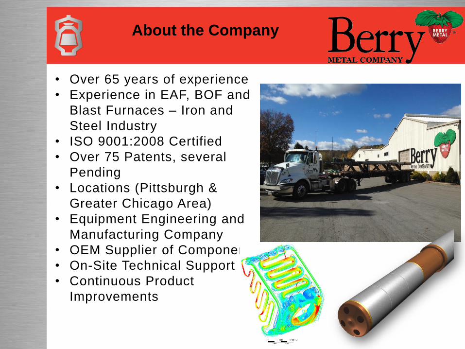
• Over 65 years of experience
• Experience in EAF, BOF and
Blast Furnaces – Iron and
Steel Industry
• ISO 9001:2008 Certified
• Over 75 Patents, several
Pending
• Locations (Pittsburgh &
Greater Chicago Area)
• Equipment Engineering and
Manufacturing Company
• OEM Supplier of Components
• On-Site Technical Support
• Continuous Product
Improvements
Engineering Capabilities
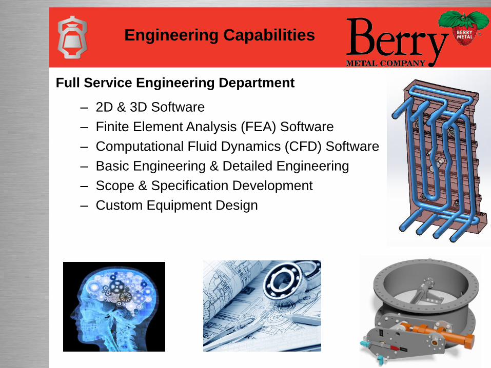
Full Service Engineering Department
– 2D & 3D Software
– Finite Element Analysis (FEA) Software
– Computational Fluid Dynamics (CFD) Software
– Basic Engineering & Detailed Engineering
– Scope & Specification Development
– Custom Equipment Design
• This project was to support a bid proposal.
• Customer had blast furnace staves that were
failing after 15 years and was looking to
replace two rows.
• Analyze the customers incumbent staves
using ANSYS and determined why they failed
• Identified other potential failure points
• Show by analysis why Berry Metal Ultra-Life
staves would not fail in the same way
Project Description
Background of the Problem
Blast Furnace Background
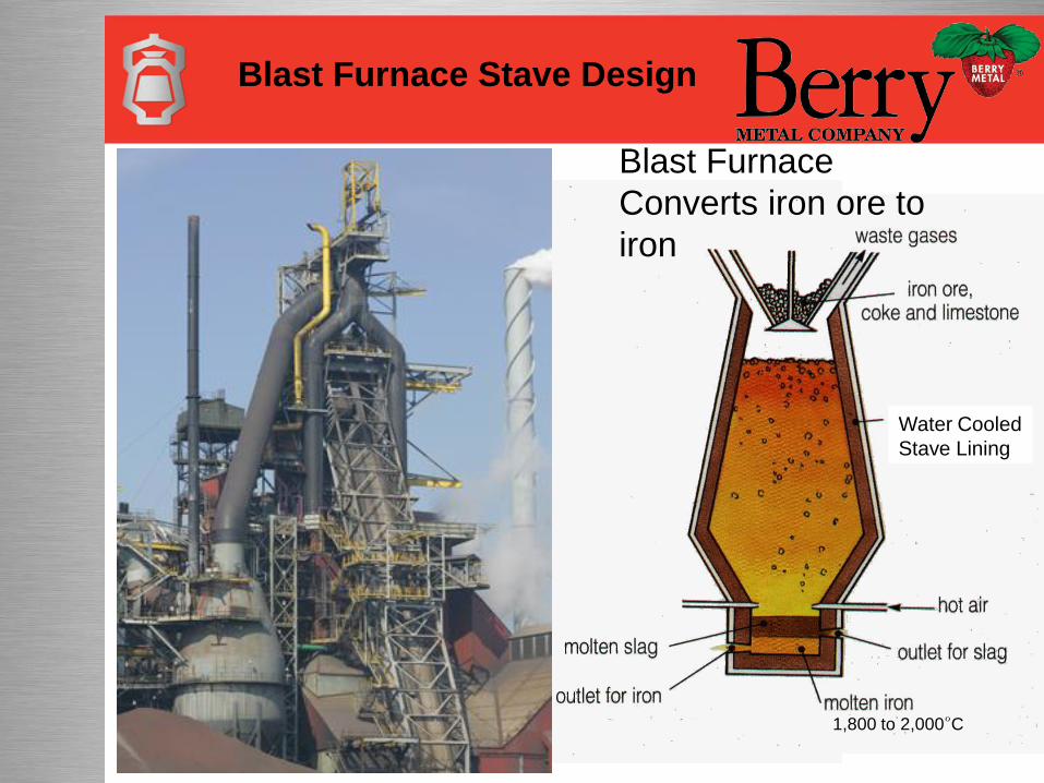
Blast Furnace Stave Design
Water Cooled
Stave LiningWater Cooled
Stave Lining
Blast Furnace
Converts iron ore to
iron
1,800 to 2,000°C
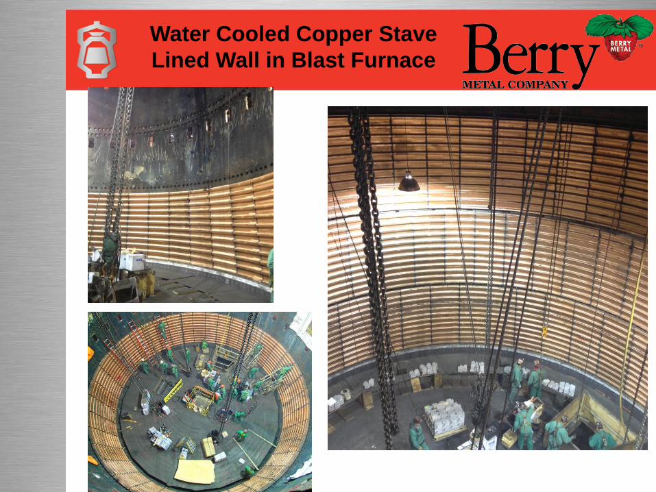
Water Cooled Copper Stave
Lined Wall in Blast Furnace
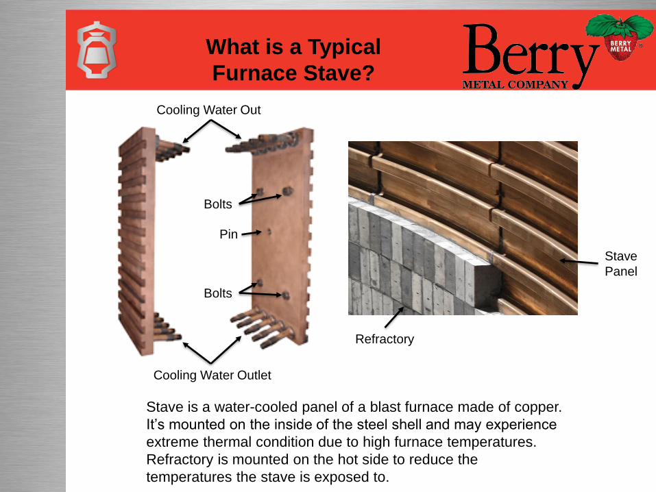
What is a Typical
Furnace Stave?
Cooling Water Out
Cooling Water Outlet
Bolts
Pin
Bolts
Refractory
Stave
Panel
Stave is a water-cooled panel of a blast furnace made of copper.
It’s mounted on the inside of the steel shell and may experience
extreme thermal condition due to high furnace temperatures.
Refractory is mounted on the hot side to reduce the
temperatures the stave is exposed to.
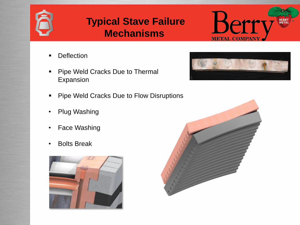
Typical Stave Failure
Mechanisms
Deflection
Pipe Weld Cracks Due to Thermal
Expansion
Pipe Weld Cracks Due to Flow Disruptions
• Plug Washing
• Face Washing
• Bolts Break
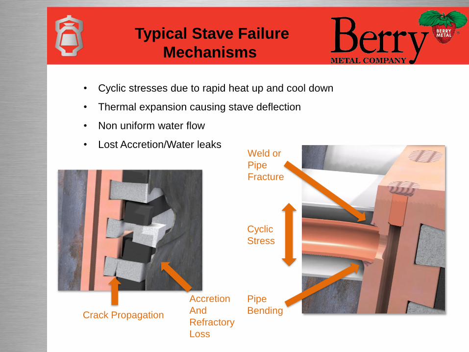
• Cyclic stresses due to rapid heat up and cool down
• Thermal expansion causing stave deflection
• Non uniform water flow
• Lost Accretion/Water leaksWeld or
Pipe
Fracture
Cyclic
Stress
Pipe
Bending
Accretion
And
Refractory
Loss
Crack Propagation
Typical Stave Failure
Mechanisms
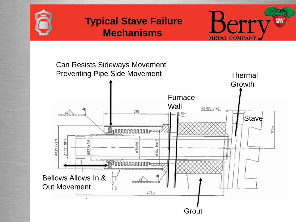
Stave
Thermal
Growth
Grout
Furnace
Wall
Can Resists Sideways Movement
Preventing Pipe Side Movement
Bellows Allows In &
Out Movement
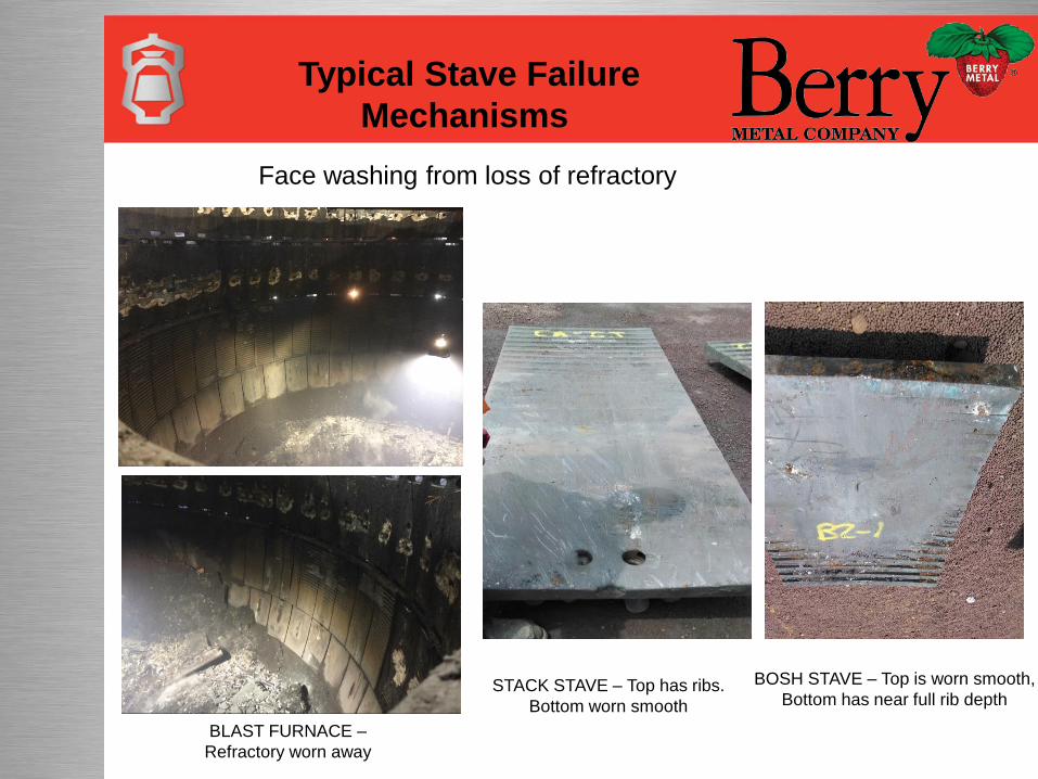
Typical Stave Failure
Mechanisms
Typical Stave Failure
Mechanisms
BOSH STAVE – Top is worn smooth,
Bottom has near full rib depthSTACK STAVE – Top has ribs.
Bottom worn smooth
Face washing from loss of refractory
BLAST FURNACE –
Refractory worn away
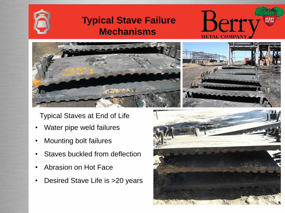
• Water pipe weld failures
• Mounting bolt failures
• Staves buckled from deflection
• Abrasion on Hot Face
• Desired Stave Life is >20 years
Typical Staves at End of Life
Typical Stave Failure
Mechanisms
New Design BMC Ultra-Life Stave
BMC Ultra-Life Stave
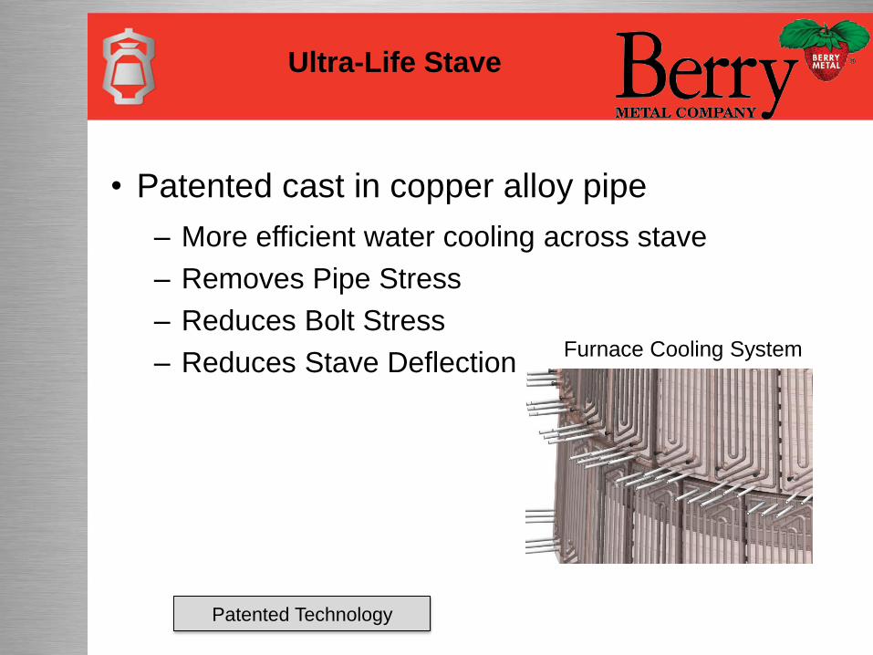
• Patented cast in copper alloy pipe
– More efficient water cooling across stave
– Removes Pipe Stress
– Reduces Bolt Stress
– Reduces Stave Deflection
Patented Technology
Furnace Cooling System
Ultra-Life Stave
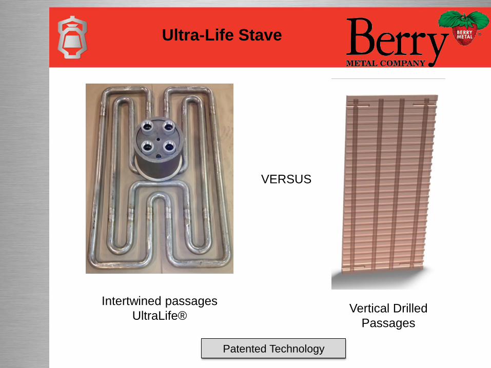
Intertwined passages
UltraLife®Vertical Drilled
Passages
VERSUS
Patented Technology
Ultra-Life Stave
Simulation
Simulation
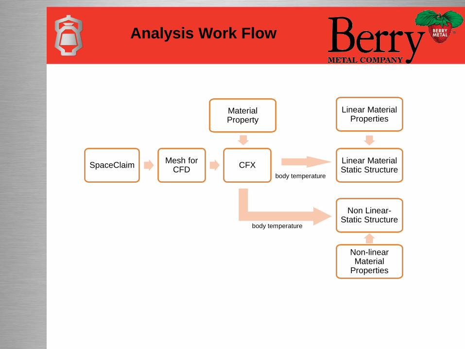
Analysis Work Flow
body temperature
SpaceClaimMesh for
CFDCFX
Linear Material Static Structure
Linear Material Properties
Non Linear-Static Structure
Material Property
Non-linear Material
Properties
body temperature
SpaceClaim
SpaceClaim
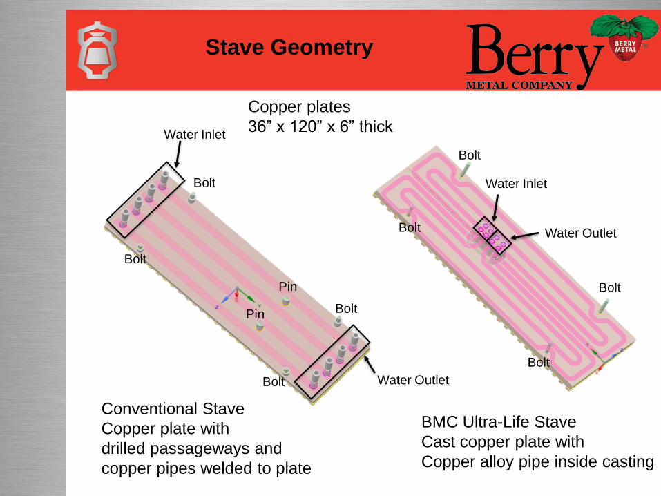
Stave Geometry
Conventional Stave
Copper plate with
drilled passageways and
copper pipes welded to plate
BMC Ultra-Life Stave
Cast copper plate with
Copper alloy pipe inside casting
Water Outlet
Water Inlet
Water Inlet
Water Outlet
Bolt
Bolt
Bolt
Bolt
Bolt
Bolt
Bolt
Pin
Pin
Bolt
Copper plates
36” x 120” x 6” thick
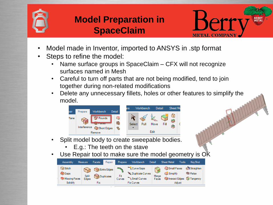
Model Preparation in
SpaceClaim
• Model made in Inventor, imported to ANSYS in .stp format
• Steps to refine the model:• Name surface groups in SpaceClaim – CFX will not recognize
surfaces named in Mesh
• Careful to turn off parts that are not being modified, tend to join
together during non-related modifications
• Delete any unnecessary fillets, holes or other features to simplify the
model.
• Split model body to create sweepable bodies.
• E.g.: The teeth on the stave
• Use Repair tool to make sure the model geometry is OK
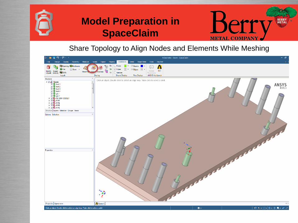
Model Preparation in
SpaceClaim
Share Topology to Align Nodes and Elements While Meshing
CFD Mesh
Model Preparation in
CFD Meshing
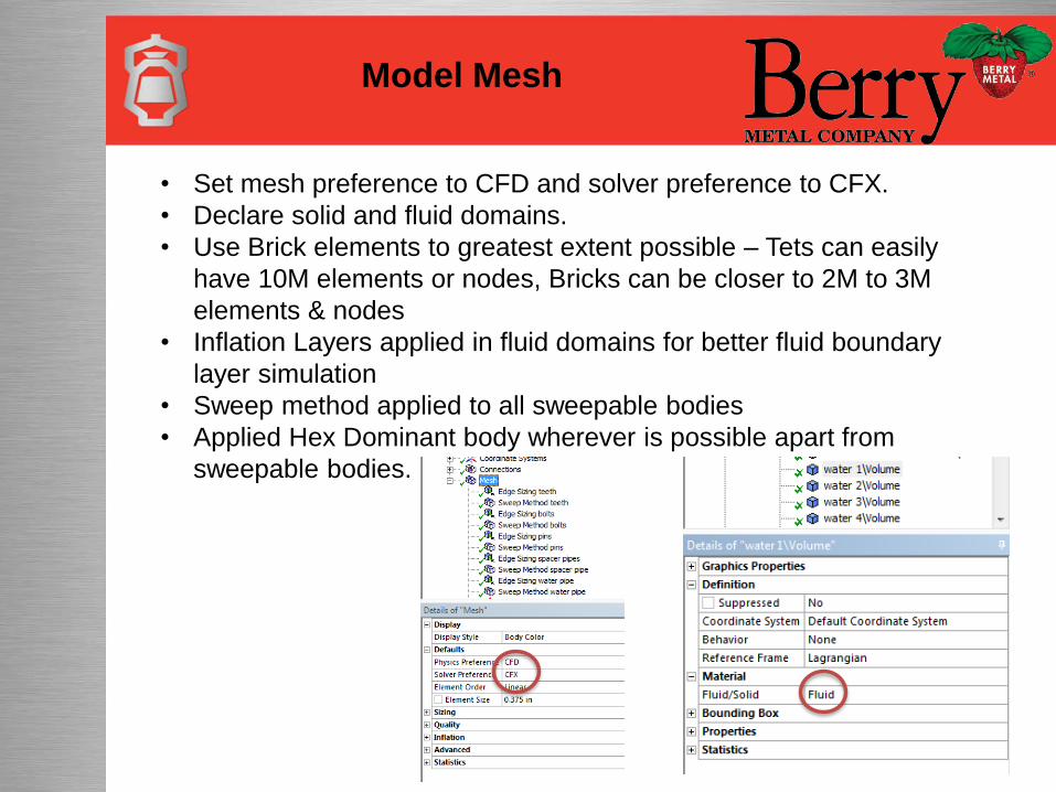
Model Mesh
• Set mesh preference to CFD and solver preference to CFX.
• Declare solid and fluid domains.
• Use Brick elements to greatest extent possible – Tets can easily
have 10M elements or nodes, Bricks can be closer to 2M to 3M
elements & nodes
• Inflation Layers applied in fluid domains for better fluid boundary
layer simulation
• Sweep method applied to all sweepable bodies
• Applied Hex Dominant body wherever is possible apart from
sweepable bodies.

Model Mesh – Stave Body
Sweep method
Sweep method
Hex Dominant
method
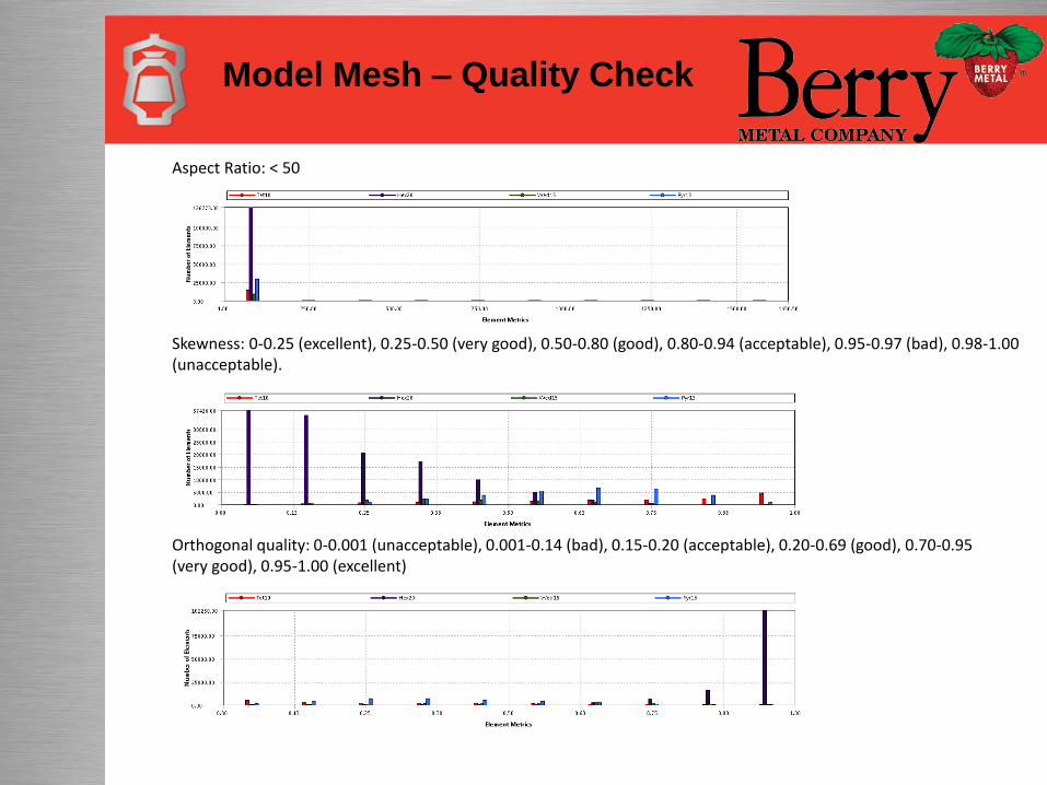
Model Mesh – Quality Check
Aspect Ratio: < 50
Skewness: 0-0.25 (excellent), 0.25-0.50 (very good), 0.50-0.80 (good), 0.80-0.94 (acceptable), 0.95-0.97 (bad), 0.98-1.00 (unacceptable).
Orthogonal quality: 0-0.001 (unacceptable), 0.001-0.14 (bad), 0.15-0.20 (acceptable), 0.20-0.69 (good), 0.70-0.95 (very good), 0.95-1.00 (excellent)
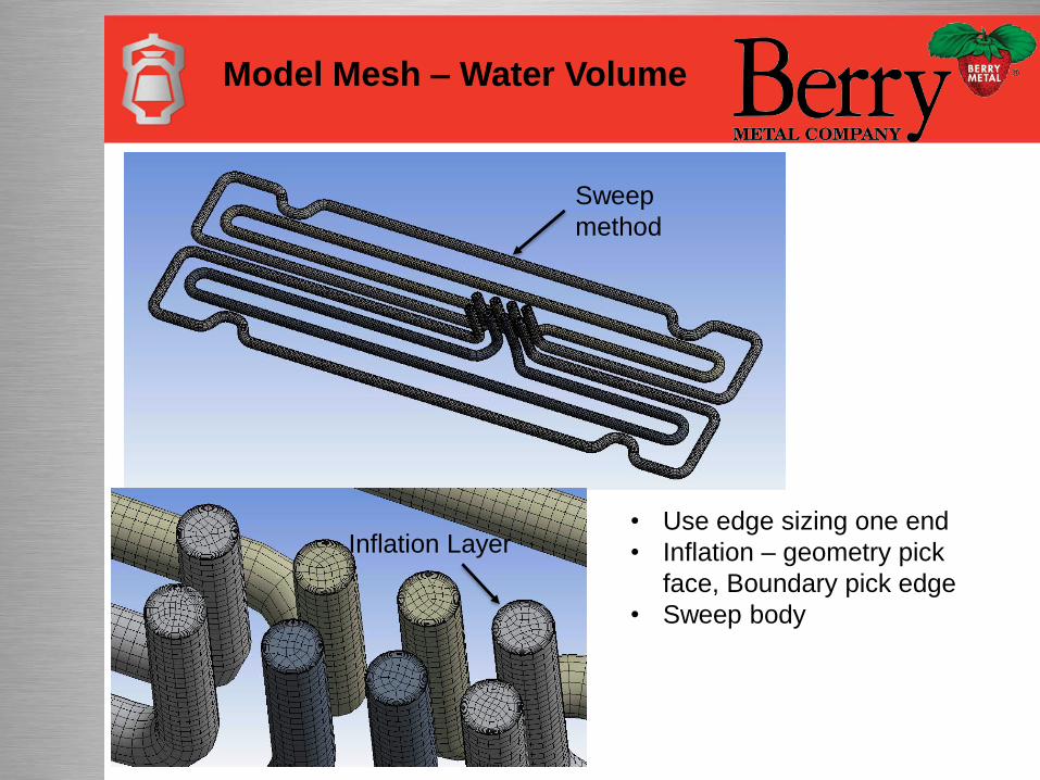
Model Mesh – Water Volume
Sweep
method
Inflation Layer• Use edge sizing one end
• Inflation – geometry pick
face, Boundary pick edge
• Sweep body
CFX
CFX
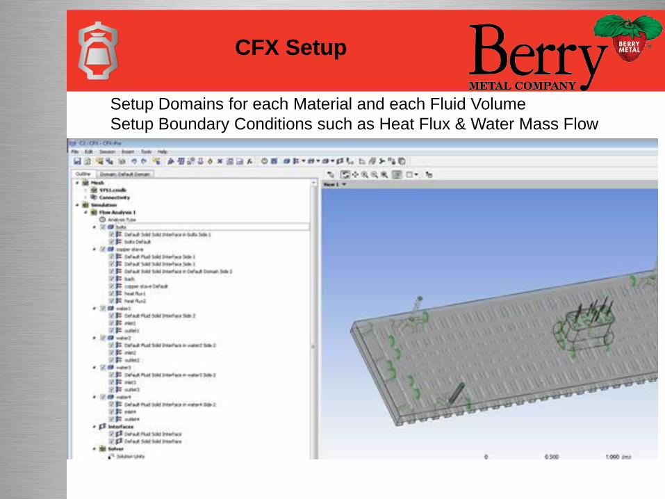
CFX Setup
Setup Domains for each Material and each Fluid Volume
Setup Boundary Conditions such as Heat Flux & Water Mass Flow
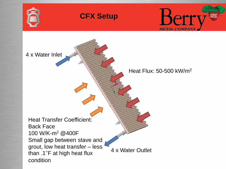
CFX Setup
Heat Flux: 50-500 kW/m2
Heat Transfer Coefficient:
Back Face
100 W/K-m2 @400F
Small gap between stave and
grout, low heat transfer – less than .1°F at high heat flux
condition
4 x Water Inlet
4 x Water Outlet
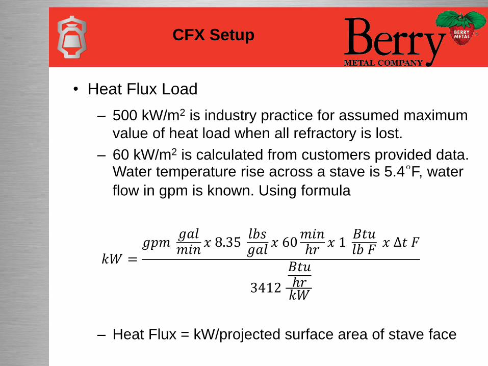
• Heat Flux Load
– 500 kW/m2 is industry practice for assumed maximum
value of heat load when all refractory is lost.
– 60 kW/m2 is calculated from customers provided data. Water temperature rise across a stave is 5.4°F, water
flow in gpm is known. Using formula
𝑘𝑊 =𝑔𝑝𝑚
𝑔𝑎𝑙𝑚𝑖𝑛
𝑥 8.35𝑙𝑏𝑠𝑔𝑎𝑙
𝑥 60𝑚𝑖𝑛ℎ𝑟
𝑥 1𝐵𝑡𝑢𝑙𝑏 𝐹
𝑥 ∆𝑡 𝐹
3412
𝐵𝑡𝑢ℎ𝑟𝑘𝑊
– Heat Flux = kW/projected surface area of stave face
CFX Setup
CFX Setup
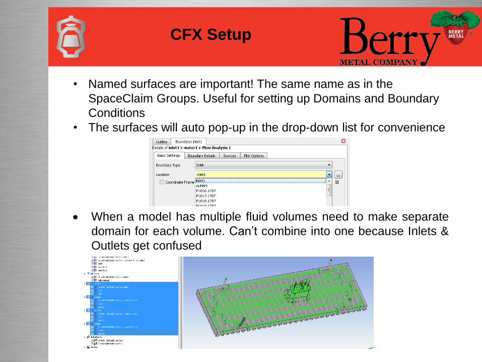
• Named surfaces are important! The same name as in the
SpaceClaim Groups. Useful for setting up Domains and Boundary
Conditions
• The surfaces will auto pop-up in the drop-down list for convenience
When a model has multiple fluid volumes need to make separate
domain for each volume. Can’t combine into one because Inlets &
Outlets get confused
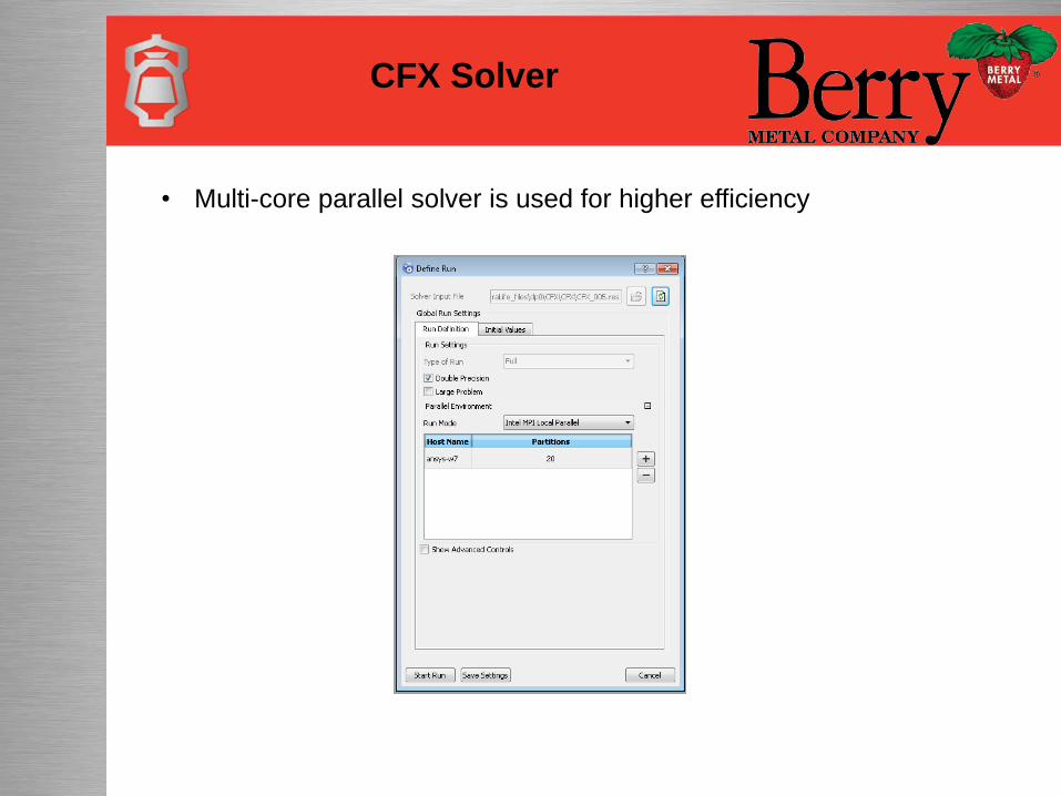
CFX Solver
• Multi-core parallel solver is used for higher efficiency
CFX Results Comparison
CFX Results Comparison
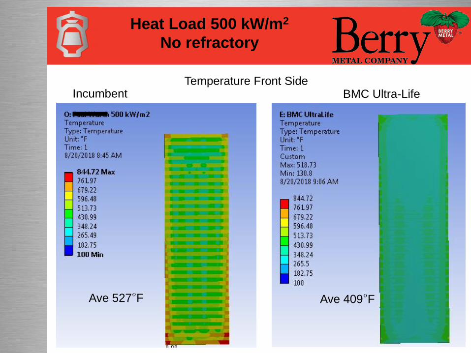
Incumbent BMC Ultra-LifeTemperature Front Side
Heat Load 500 kW/m2
No refractory
Ave 409°FAve 527°F
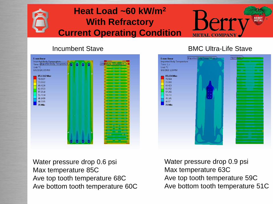
Water pressure drop 0.6 psi
Max temperature 85C
Ave top tooth temperature 68C
Ave bottom tooth temperature 60C
Water pressure drop 0.9 psi
Max temperature 63C
Ave top tooth temperature 59C
Ave bottom tooth temperature 51C
Incumbent Stave BMC Ultra-Life Stave
Heat Load ~60 kW/m2
With Refractory
Current Operating Condition
Linear Material Structural Setup
Linear Material Structural
Setup
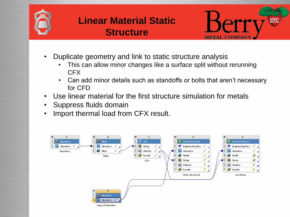
Linear Material Static
Structure
• Duplicate geometry and link to static structure analysis• This can allow minor changes like a surface split without rerunning
CFX
• Can add minor details such as standoffs or bolts that aren’t necessary
for CFD
• Use linear material for the first structure simulation for metals
• Suppress fluids domain
• Import thermal load from CFX result.

Stave Load and Support
Bolts – Fixed End Support
Pins - Sliding Support by Shell
Backside - Support by
Grout to Shell
Pipes – Bellows free on axial, fixed on
side loads
Bolts – Fixed End Support
Pipe Manifold –
Welded to Shell
Incumbent Stave Design Ultra-Life Stave Design
Backside - Support by
Grout to Shell
Gravity down Gravity down
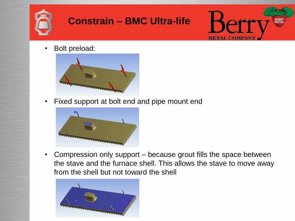
Constrain – BMC Ultra-life
• Bolt preload:
• Fixed support at bolt end and pipe mount end
• Compression only support – because grout fills the space between
the stave and the furnace shell. This allows the stave to move away
from the shell but not toward the shell
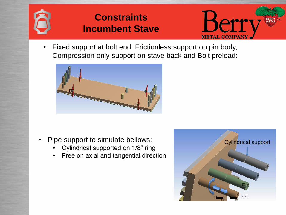
Constraints
Incumbent Stave
• Fixed support at bolt end, Frictionless support on pin body,
Compression only support on stave back and Bolt preload:
• Pipe support to simulate bellows:• Cylindrical supported on 1/8’’ ring
• Free on axial and tangential direction
Cylindrical support
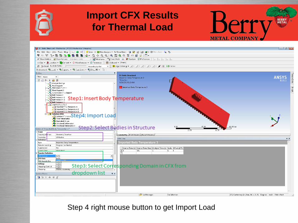
Import CFX Results
for Thermal Load
Step 4 right mouse button to get Import Load
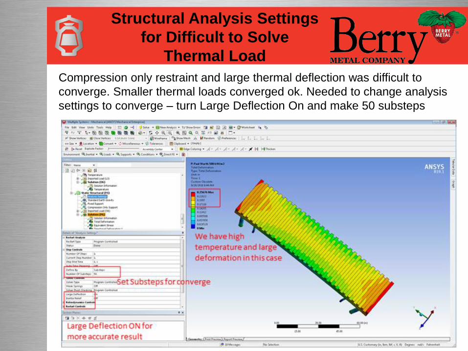
Structural Analysis Settings
for Difficult to Solve
Thermal Load
Compression only restraint and large thermal deflection was difficult to
converge. Smaller thermal loads converged ok. Needed to change analysis
settings to converge – turn Large Deflection On and make 50 substeps
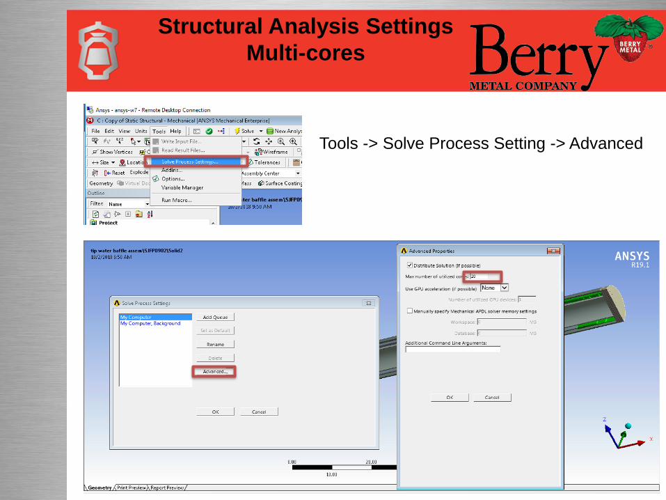
Structural Analysis Settings
Multi-cores
Tools -> Solve Process Setting -> Advanced
Structural Analysis
Results Comparison
Linear Material
Structural Analysis
Results Comparison
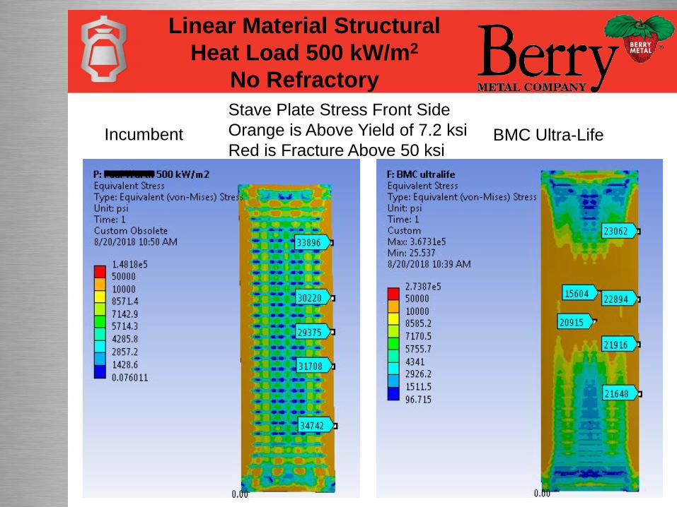
Linear Material Structural
Heat Load 500 kW/m2
No Refractory
Incumbent BMC Ultra-Life
Stave Plate Stress Front Side
Orange is Above Yield of 7.2 ksi
Red is Fracture Above 50 ksi
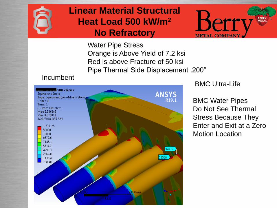
Incumbent
Water Pipe Stress
Orange is Above Yield of 7.2 ksi
Red is above Fracture of 50 ksi
Pipe Thermal Side Displacement .200”
BMC Ultra-Life
BMC Water Pipes
Do Not See Thermal
Stress Because They
Enter and Exit at a Zero
Motion Location
Linear Material Structural
Heat Load 500 kW/m2
No Refractory
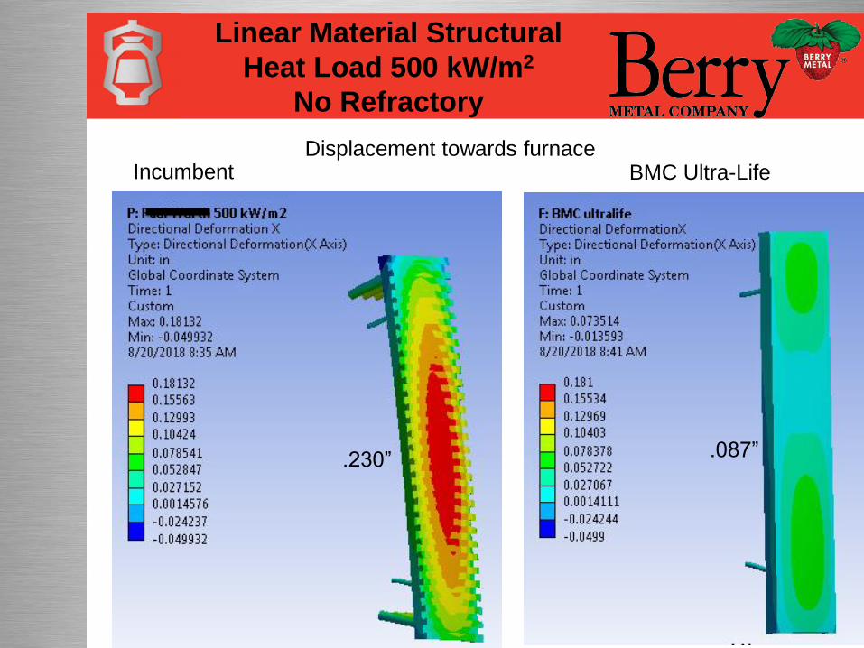
Displacement towards furnaceIncumbent
.230” .087”
BMC Ultra-Life
Linear Material Structural
Heat Load 500 kW/m2
No Refractory
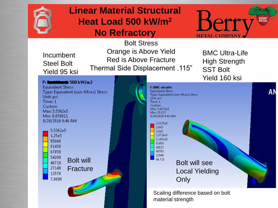
Incumbent
Steel Bolt
Yield 95 ksi
BMC Ultra-Life
High Strength
SST Bolt
Yield 160 ksi
Bolt Stress
Orange is Above Yield
Red is Above Fracture
Thermal Side Displacement .115”
Bolt will
FractureBolt will see
Local Yielding
Only
Scaling difference based on bolt
material strength
Linear Material Structural
Heat Load 500 kW/m2
No Refractory

Stave max stress exceeds yield of
7.2 ksi and ultimate of 22 ksiStave body max stress 21 ksi
exceeds yield but below ultimate
Conventional Stave BMC Ultra-Life Stave
Linear Material Structural
Heat Load 60 kW/m2
With Refractory
Non-Linear Material Properties in Engineering Data
Non-Linear Material
Properties
Due to high stress, customer requested non-linear (plastic) analysis
with their current thermal operating conditions. We do not have
non-linear data on copper and had to approximate it.
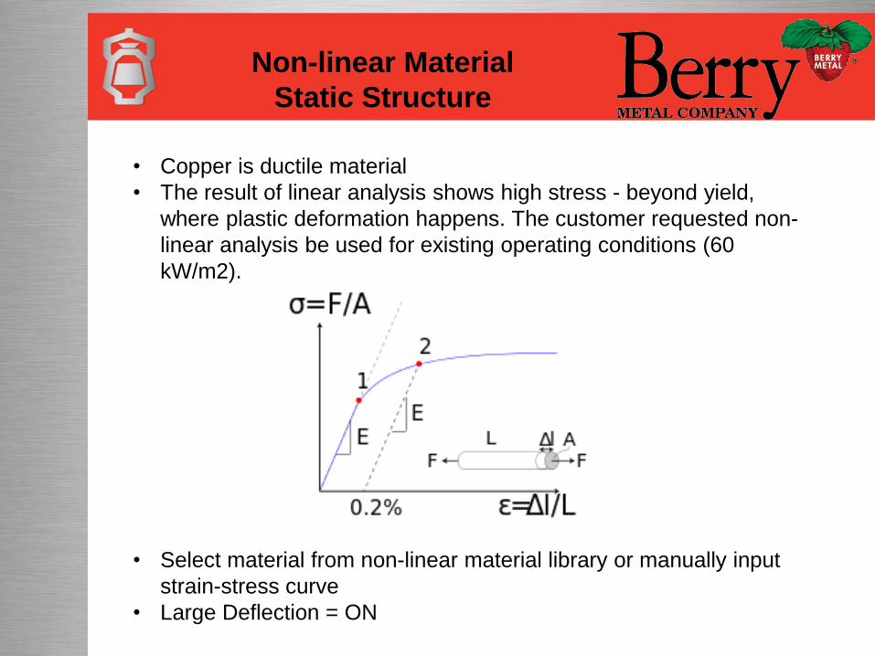
Non-linear Material
Static Structure
• Copper is ductile material
• The result of linear analysis shows high stress - beyond yield,
where plastic deformation happens. The customer requested non-
linear analysis be used for existing operating conditions (60
kW/m2).
• Select material from non-linear material library or manually input
strain-stress curve
• Large Deflection = ON
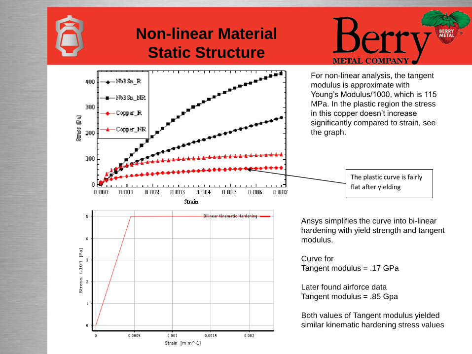
Ansys simplifies the curve into bi-linear
hardening with yield strength and tangent
modulus.
Curve for
Tangent modulus = .17 GPa
Later found airforce data
Tangent modulus = .85 Gpa
Both values of Tangent modulus yielded
similar kinematic hardening stress values
Non-linear Material
Static Structure
The plastic curve is fairly
flat after yielding
For non-linear analysis, the tangent
modulus is approximate with
Young’s Modulus/1000, which is 115
MPa. In the plastic region the stress
in this copper doesn’t increase
significantly compared to strain, see
the graph.
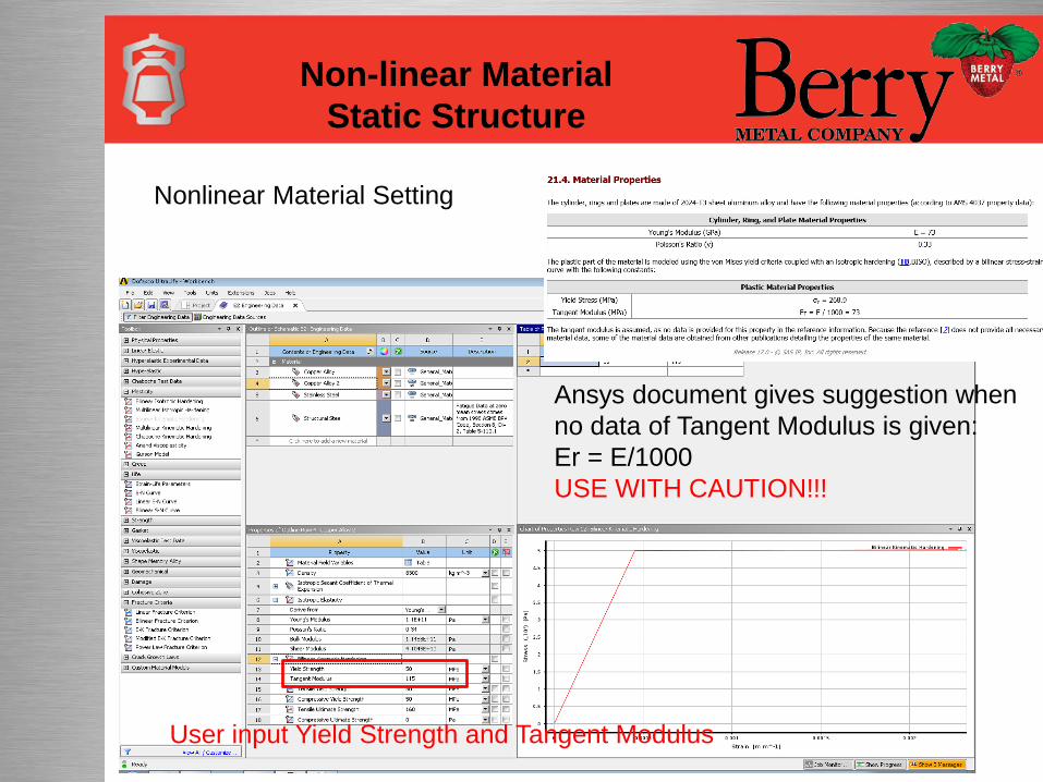
Ansys document gives suggestion when
no data of Tangent Modulus is given:
Er = E/1000
USE WITH CAUTION!!!
User input Yield Strength and Tangent Modulus
Nonlinear Material Setting
Non-linear Material
Static Structure
Non-Linear Material Analysis
Non-linear Material
Static Structure
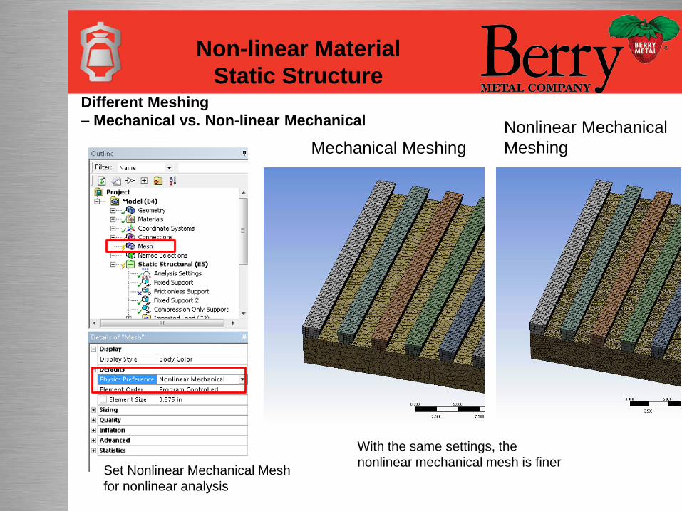
Different Meshing
– Mechanical vs. Non-linear Mechanical
Mechanical Meshing
Nonlinear Mechanical
Meshing
Set Nonlinear Mechanical Mesh
for nonlinear analysis
With the same settings, the
nonlinear mechanical mesh is finer
Non-linear Material
Static Structure
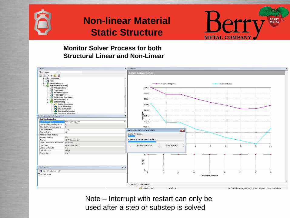
Monitor Solver Process for both
Structural Linear and Non-Linear
Non-linear Material
Static Structure
Note – Interrupt with restart can only be
used after a step or substep is solved
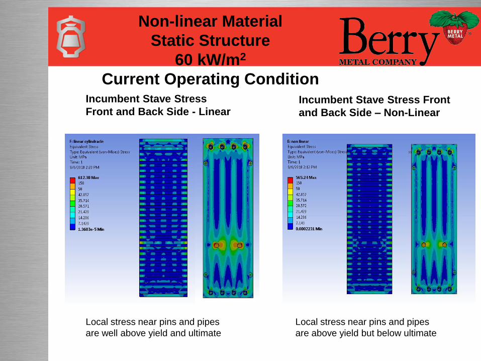
Incumbent Stave Stress
Front and Back Side - Linear
Non-linear Material
Static Structure
60 kW/m2
Current Operating Condition
Incumbent Stave Stress Front
and Back Side – Non-Linear
Local stress near pins and pipes
are well above yield and ultimate
Local stress near pins and pipes
are above yield but below ultimate
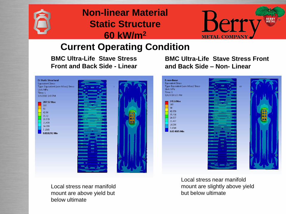
BMC Ultra-Life Stave Stress
Front and Back Side - Linear
Non-linear Material
Static Structure
60 kW/m2
Current Operating ConditionBMC Ultra-Life Stave Stress Front
and Back Side – Non- Linear
Local stress near manifold
mount are above yield but
below ultimate
Local stress near manifold
mount are slightly above yield
but below ultimate
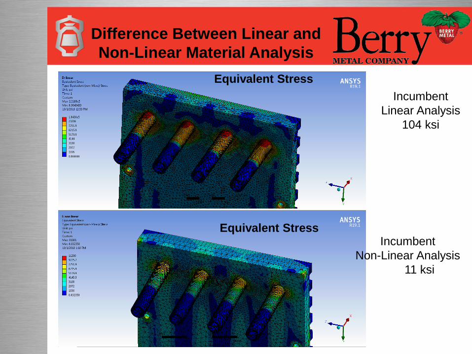
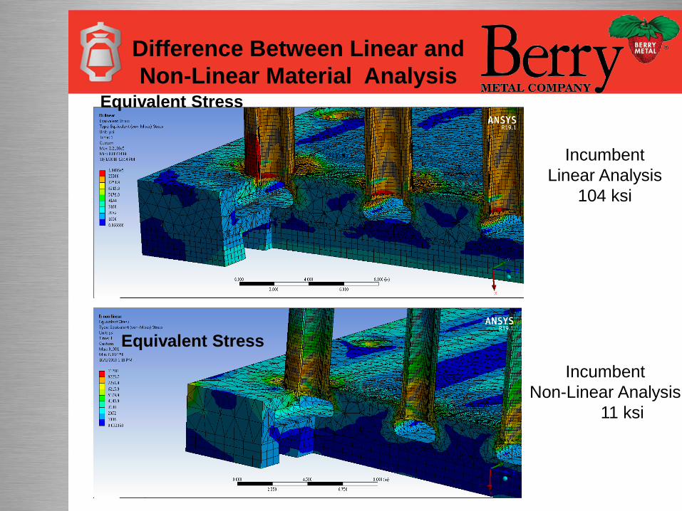
Difference Between Linear and
Non-Linear Material Analysis
Incumbent
Linear Analysis
104 ksi
Incumbent
Non-Linear Analysis
11 ksi
Equivalent Stress
Equivalent Stress
Difference Between Linear and
Non-Linear Material Analysis
Incumbent
Linear Analysis
104 ksi
Incumbent
Non-Linear Analysis
11 ksi
Equivalent Stress
Equivalent Stress
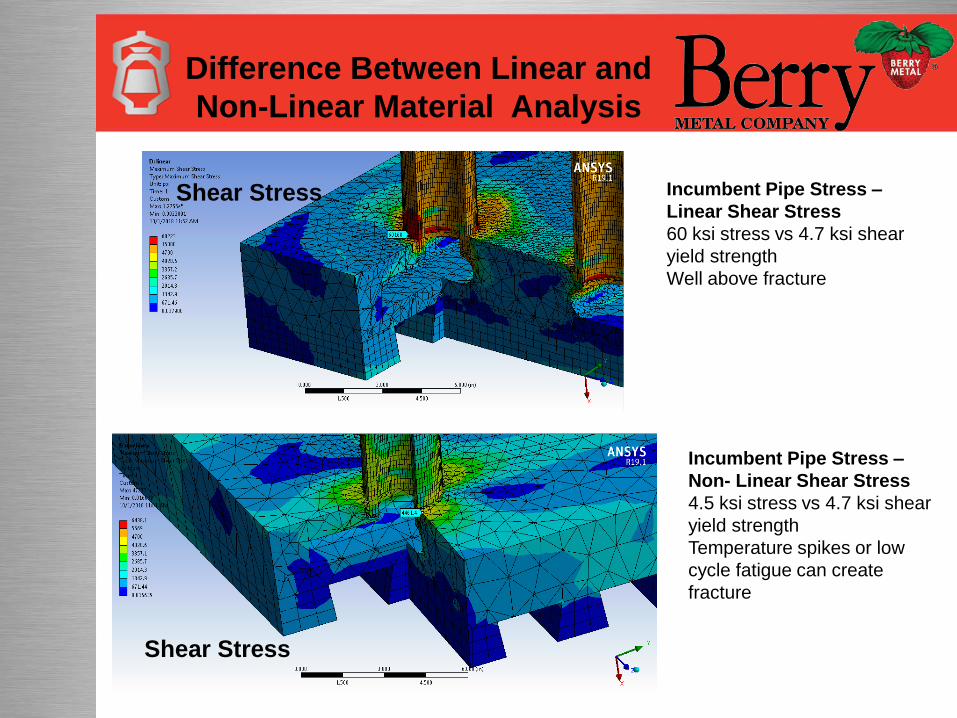
Incumbent Pipe Stress –
Non- Linear Shear Stress
4.5 ksi stress vs 4.7 ksi shear
yield strength
Temperature spikes or low
cycle fatigue can create
fracture
Incumbent Pipe Stress –
Linear Shear Stress
60 ksi stress vs 4.7 ksi shear
yield strength
Well above fracture
Difference Between Linear and
Non-Linear Material Analysis
Shear Stress
Shear Stress
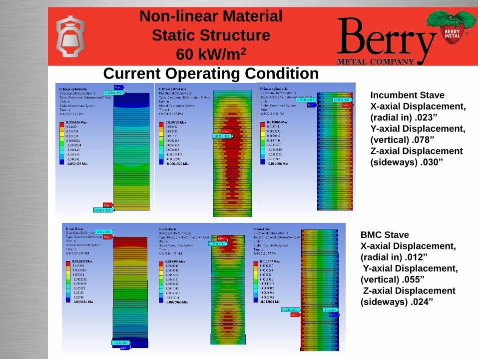
Incumbent Stave
X-axial Displacement,
(radial in) .023”
Y-axial Displacement,
(vertical) .078”
Z-axial Displacement
(sideways) .030”
BMC Stave
X-axial Displacement,
(radial in) .012”
Y-axial Displacement,
(vertical) .055”
Z-axial Displacement
(sideways) .024”
Non-linear Material
Static Structure
60 kW/m2
Current Operating Condition
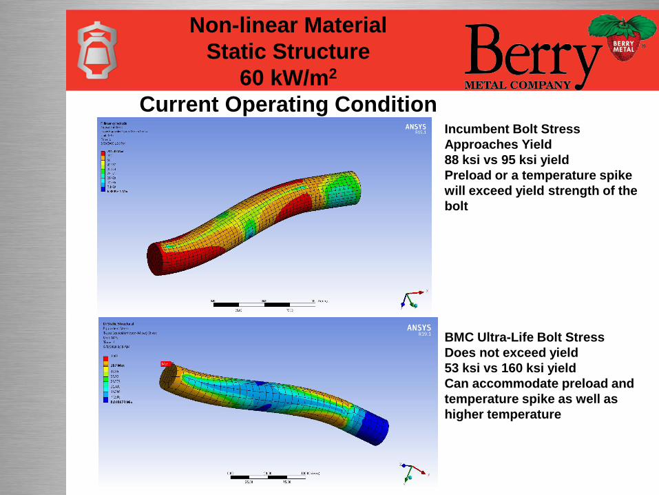
BMC Ultra-Life Bolt Stress
Does not exceed yield
53 ksi vs 160 ksi yield
Can accommodate preload and
temperature spike as well as
higher temperature
Incumbent Bolt Stress
Approaches Yield
88 ksi vs 95 ksi yield
Preload or a temperature spike
will exceed yield strength of the
bolt
Non-linear Material
Static Structure
60 kW/m2
Current Operating Condition
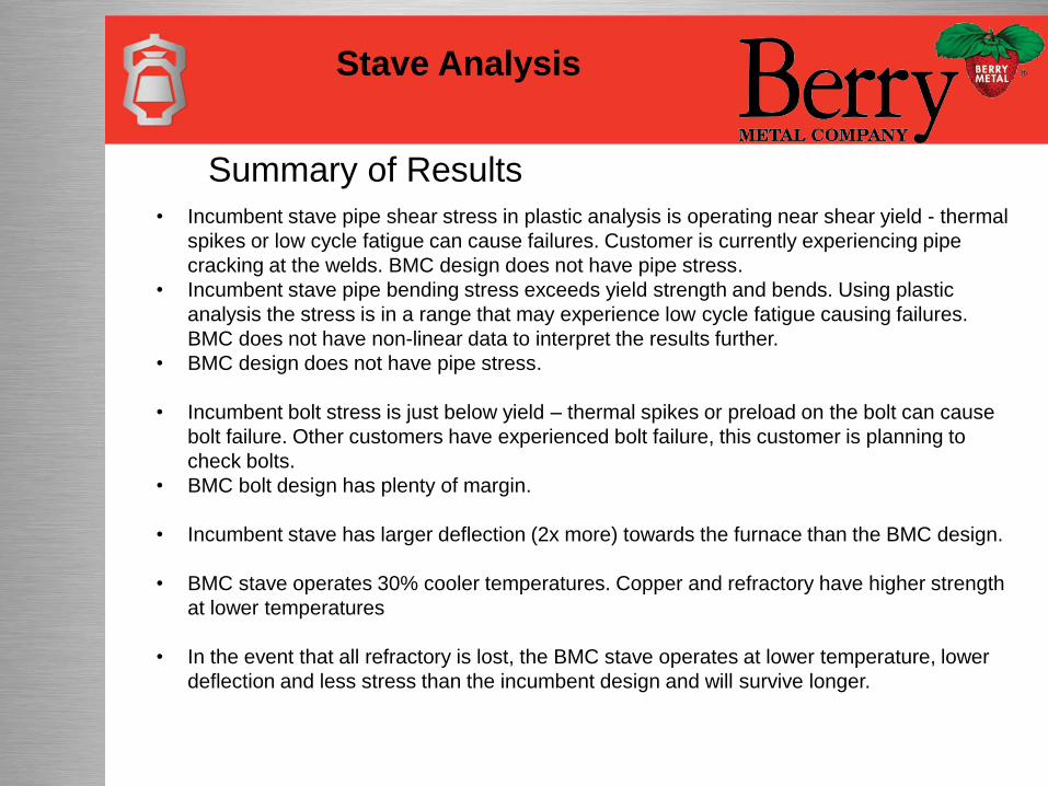
• Incumbent stave pipe shear stress in plastic analysis is operating near shear yield - thermal
spikes or low cycle fatigue can cause failures. Customer is currently experiencing pipe
cracking at the welds. BMC design does not have pipe stress.
• Incumbent stave pipe bending stress exceeds yield strength and bends. Using plastic
analysis the stress is in a range that may experience low cycle fatigue causing failures.
BMC does not have non-linear data to interpret the results further.
• BMC design does not have pipe stress.
• Incumbent bolt stress is just below yield – thermal spikes or preload on the bolt can cause
bolt failure. Other customers have experienced bolt failure, this customer is planning to
check bolts.
• BMC bolt design has plenty of margin.
• Incumbent stave has larger deflection (2x more) towards the furnace than the BMC design.
• BMC stave operates 30% cooler temperatures. Copper and refractory have higher strength
at lower temperatures
• In the event that all refractory is lost, the BMC stave operates at lower temperature, lower
deflection and less stress than the incumbent design and will survive longer.
Summary of Results
Stave Analysis
Questions?
Stave Analysis