Volkswagen Diesel Engine Development - Experimental Engine ...
Upload
centro-de-investigacion-y-tecnologia-mecanica-itmCategory
view
8.498download
21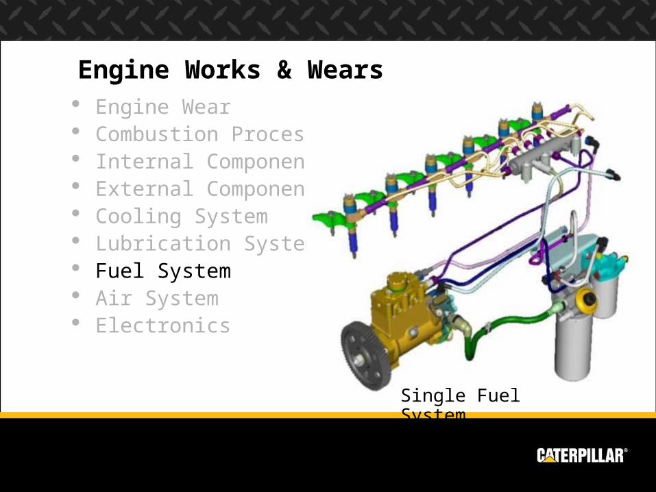
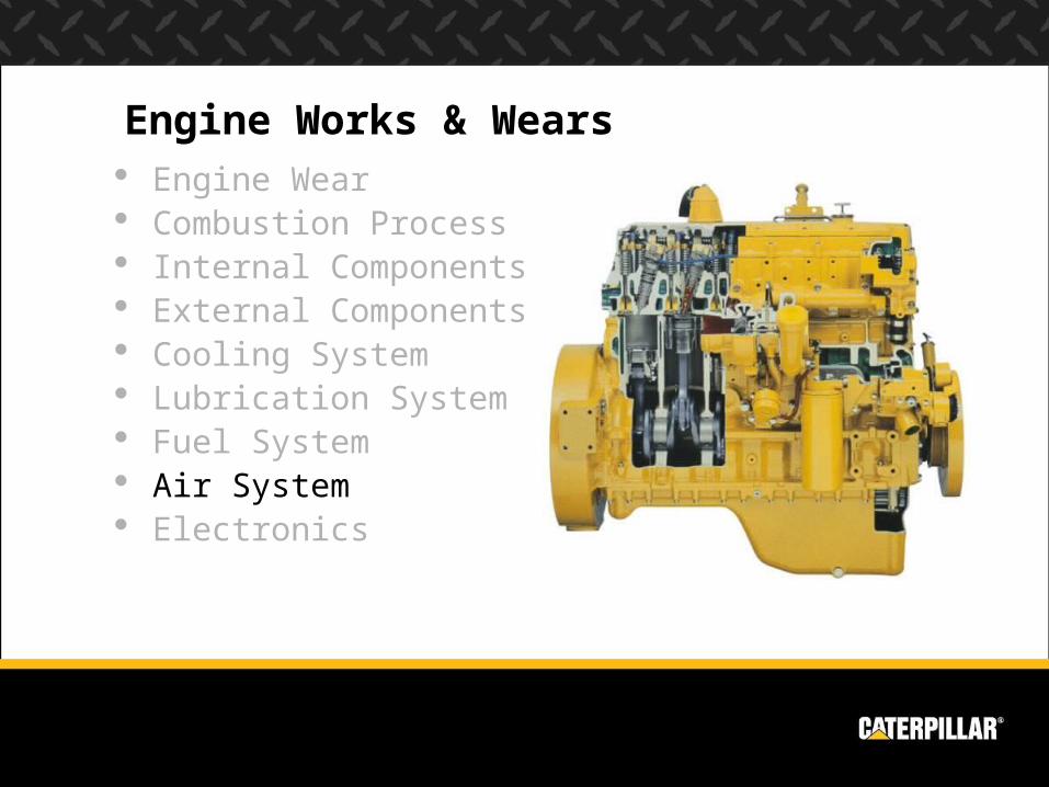
Engine Works & Wears Engine Wear Combustion Process Internal Components External Components Cooling System Lubrication System Fuel System Air System Electronics
Single Fuel System
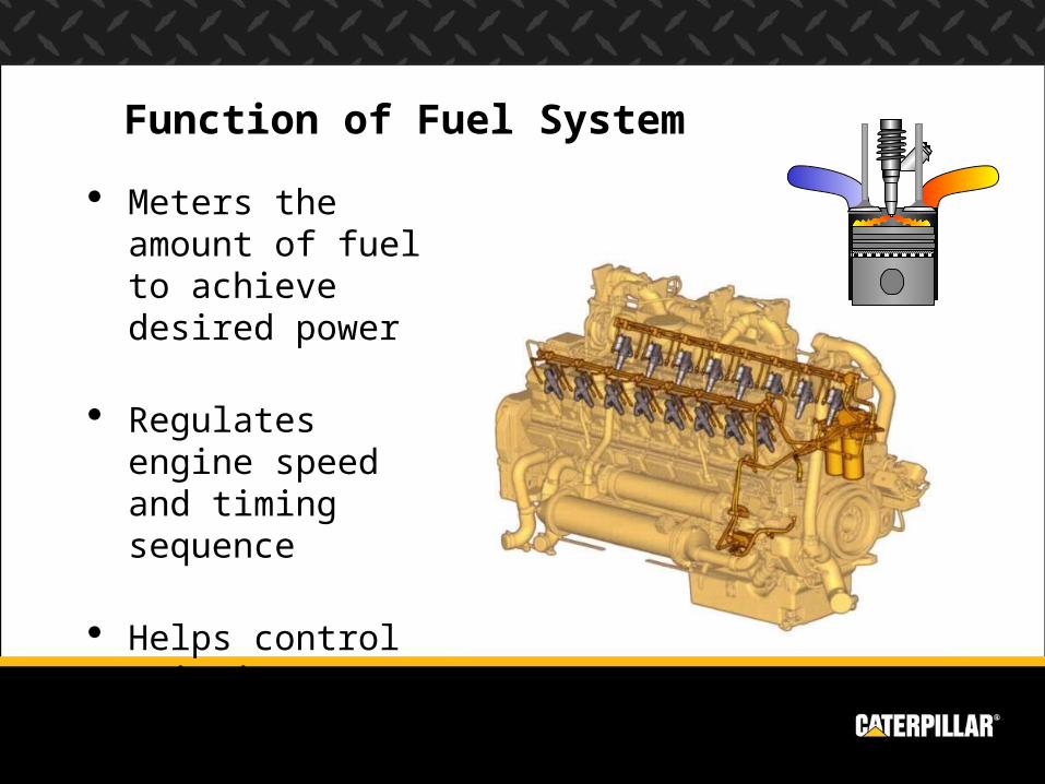
Function of Fuel System
Meters the amount of fuel to achieve desired power
Regulates engine speed and timing sequence
Helps control emissions
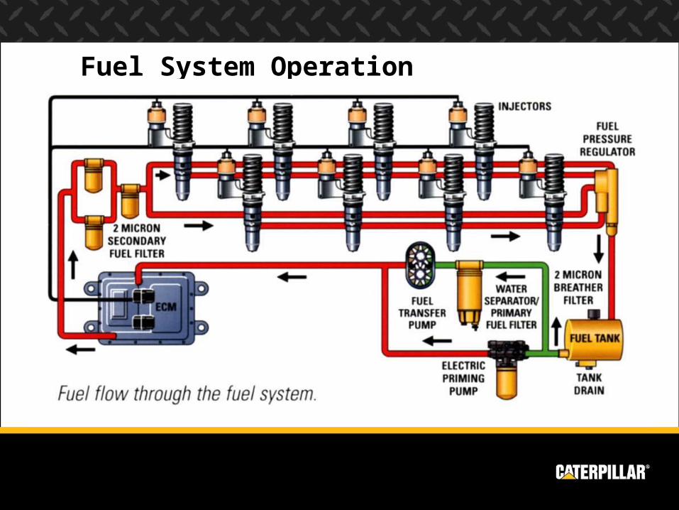
Fuel System Operation

Pump & Line Current Scroll Fuel System New Scroll Fuel System Sleeve Metering Fuel System (SMFS) Program Electronic Engine Controls (PEEC)
Timeline
1988EUI
1974 SMFS
1975 1980 1985 1990 1995 2000 2005Pre 1970 1970
1994HEUI
1987PEEC
1981MUI
2004 Rail
Types of Fuel Systems Unit Injection
MUI EUI HEUI Common
Rail(Single Fuel)1983
NSFS1973CSFS
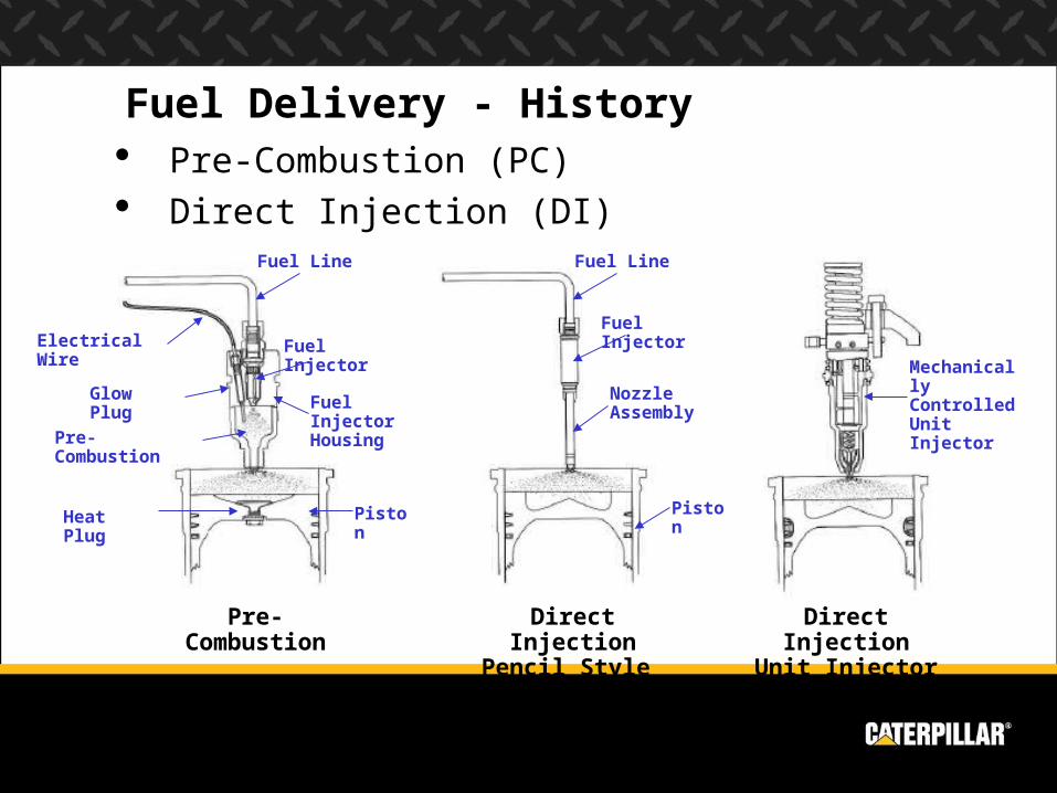
Fuel Delivery - History Pre-Combustion (PC) Direct Injection (DI)
Pre-Combustion Direct Injection Pencil Style
Direct Injection Unit Injector
Fuel Line
Fuel Injector
Glow Plug
Heat Plug Piston
Electrical Wire
Fuel Injector Housing
Pre-Combustion
Fuel Line
Fuel Injector
Piston
Nozzle Assembly
Mechanically Controlled Unit Injector
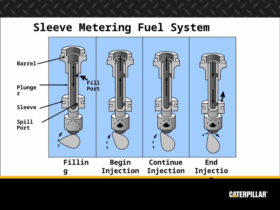
Filling Begin Injection
Continue Injection
End Injection
Barrel
Plunger
Sleeve
Fill Port
Spill Port
Sleeve Metering Fuel System
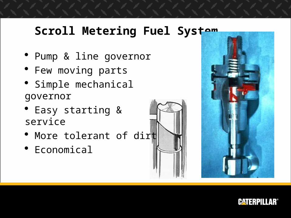
Scroll Metering Fuel System
Pump & line governor Few moving parts Simple mechanical governor Easy starting & service More tolerant of dirt Economical
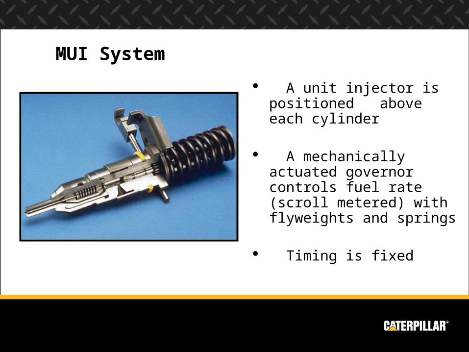
A unit injector is positioned above each cylinder
A mechanically actuated governor controls fuel rate (scroll metered) with flyweights and springs
Timing is fixed
MUI System
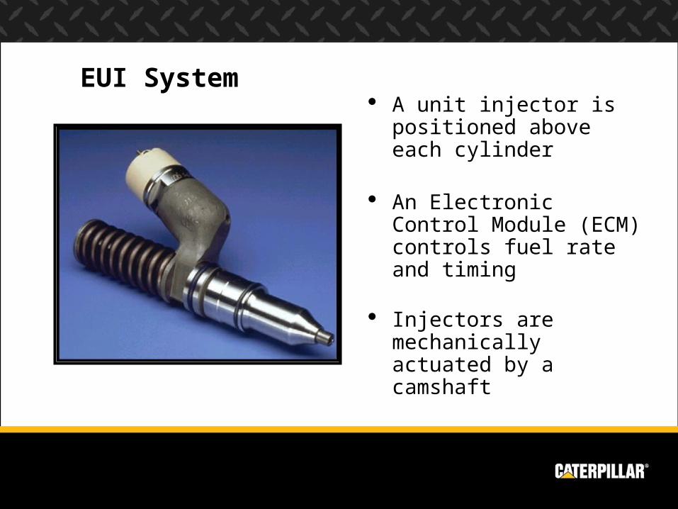
A unit injector is positioned above each cylinder
An Electronic Control Module (ECM) controls fuel rate and timing
Injectors are mechanically actuated by a camshaft
EUI System
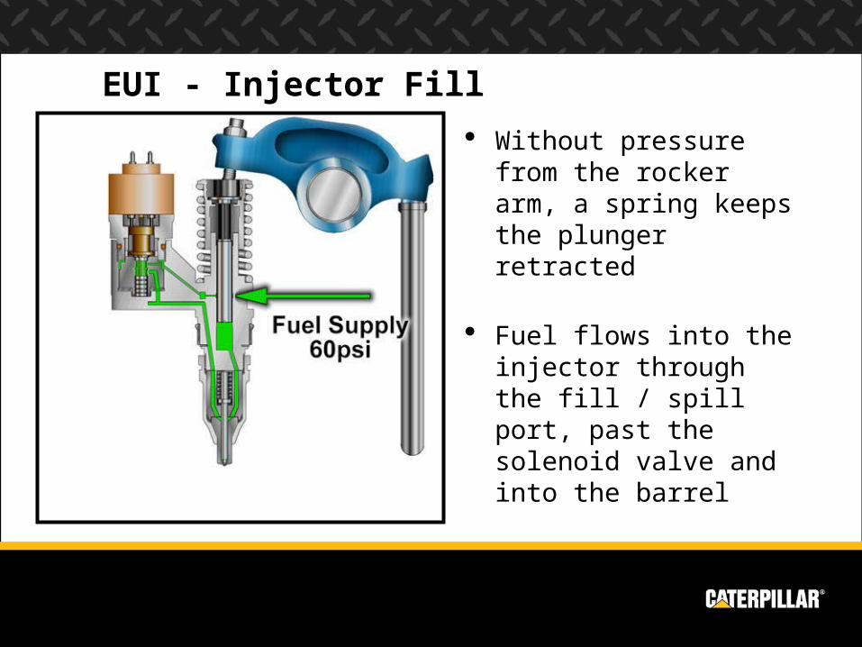
EUI - Injector Fill
Without pressure from the rocker arm, a spring keeps the plunger retracted
Fuel flows into the injector through the fill / spill port, past the solenoid valve and into the barrel
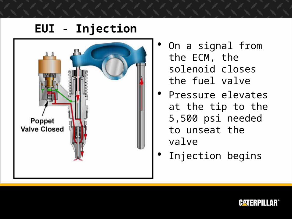
EUI - Injection On a signal from the
ECM, the solenoid closes the fuel valve
Pressure elevates at the tip to the 5,500 psi needed to unseat the valve
Injection begins
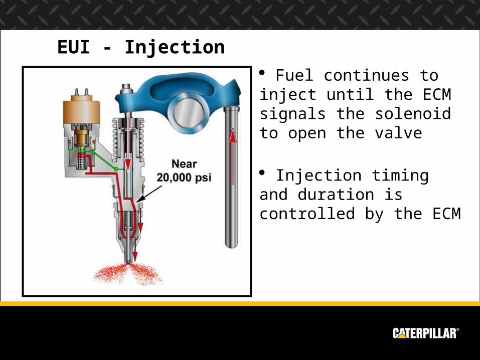
EUI - Injection Fuel continues to inject until the ECM signals the solenoid to open the valve
Injection timing and duration is controlled by the ECM
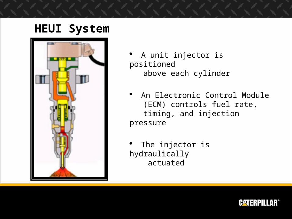
A unit injector is positioned above each cylinder
An Electronic Control Module (ECM) controls fuel rate, timing, and injection pressure
The injector is hydraulically actuated
HEUI System
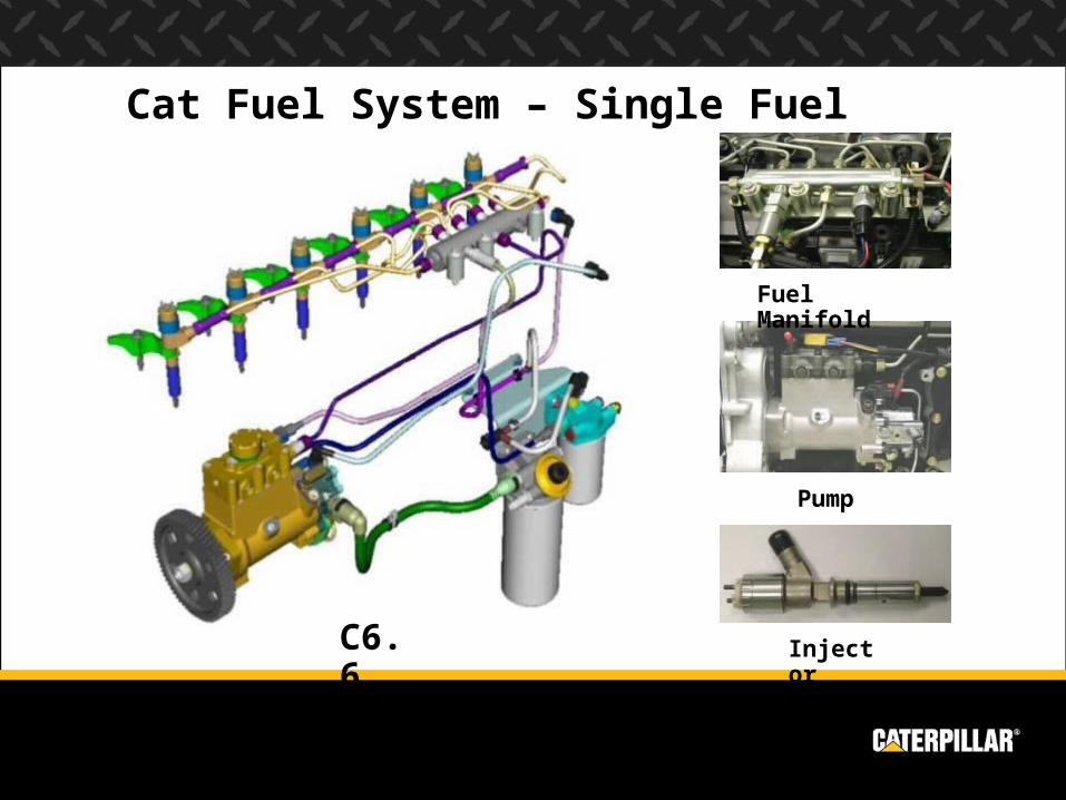
Cat Fuel System – Single Fuel
C6.6
Fuel Manifold
Pump
Injector
Fuel System Wear & Failure Causes Short unit injector life due to excessive abrasive particles in
the fuel Abrasive particles damage sealing surfaces causing leakage of
high pressure fuel and low engine power Abrasive particles are inherent in most fuels Most particles can be removed by using High Efficiency filters
Injector seizure due to excess water in the fuel Always small amounts of water in fuel, which is harmless Excess water in fuel reduces the lubricating film strength of fuel
and causes seizure of the injector plunger and barrel Maximum amount of allowable water in fuel is 0.1%
Fuel System Wear & Failure Causes Injector sticking or seizure due to fuel overheating
Fuel in the injector “cooks” and produces varnish which causes components to stick or seize
Viscosity of hot fuel is inadequate and the fuel film thickness will not provide adequate protection against scuffing or seizure of the plunger and barrel
Fuel overheating can be caused by operating in extreme ambient temperatures. An auxiliary fuel cooler installed in the fuel supply line to the cylinder heads may be required to limit fuel temperatures
Running fuel tank too low, or running out of fuel causes the fuel to cycle through the engine too frequently and becomes very hot. This can be avoided by keeping the fuel tank levels at ¼ full or above
Fuel System Wear & Failure Causes Poor quality oil
Fuel may be low in viscosity or lubricity. Fuel which is old or oxidized often contains excessive gums or resins which promotes injector sticking or seizure.
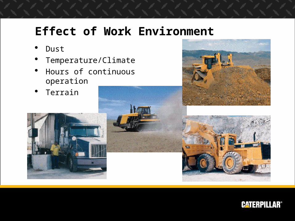
Effect of Work Environment Dust Temperature/Climate Hours of continuous operation Terrain
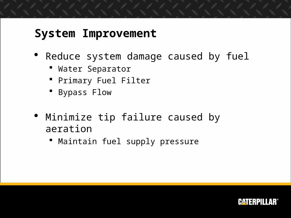
System Improvement
Reduce system damage caused by fuel Water Separator Primary Fuel Filter Bypass Flow
Minimize tip failure caused by aeration Maintain fuel supply pressure
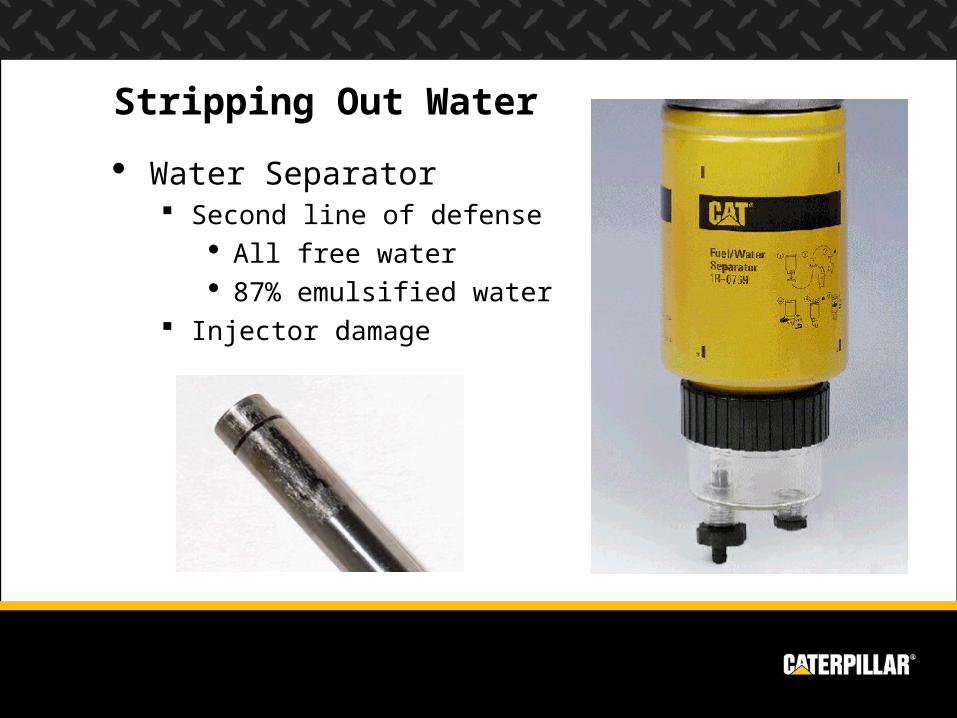
Stripping Out Water
Water Separator Second line of defense
All free water 87% emulsified water
Injector damage
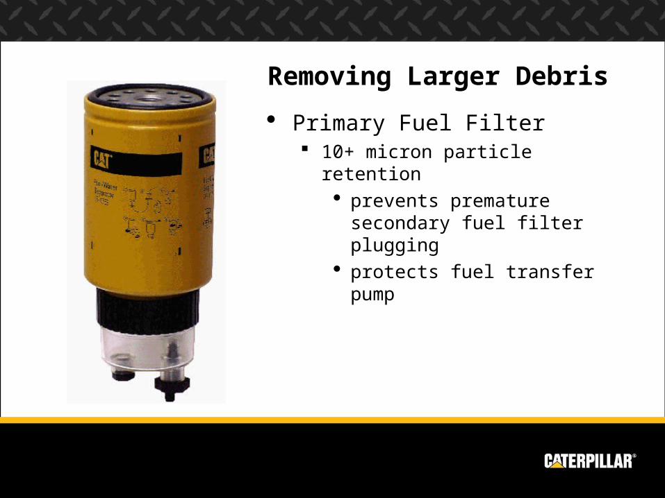
Removing Larger Debris
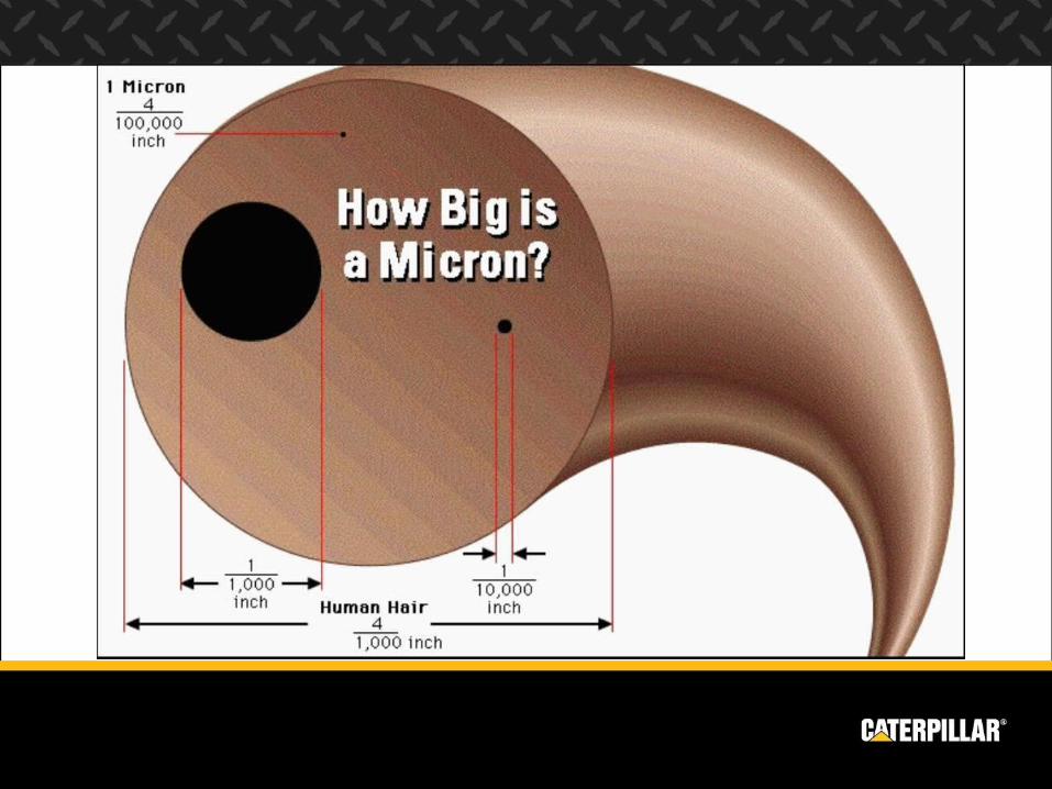
Primary Fuel Filter 10+ micron particle retention
prevents premature secondary fuel filter plugging
protects fuel transfer pump
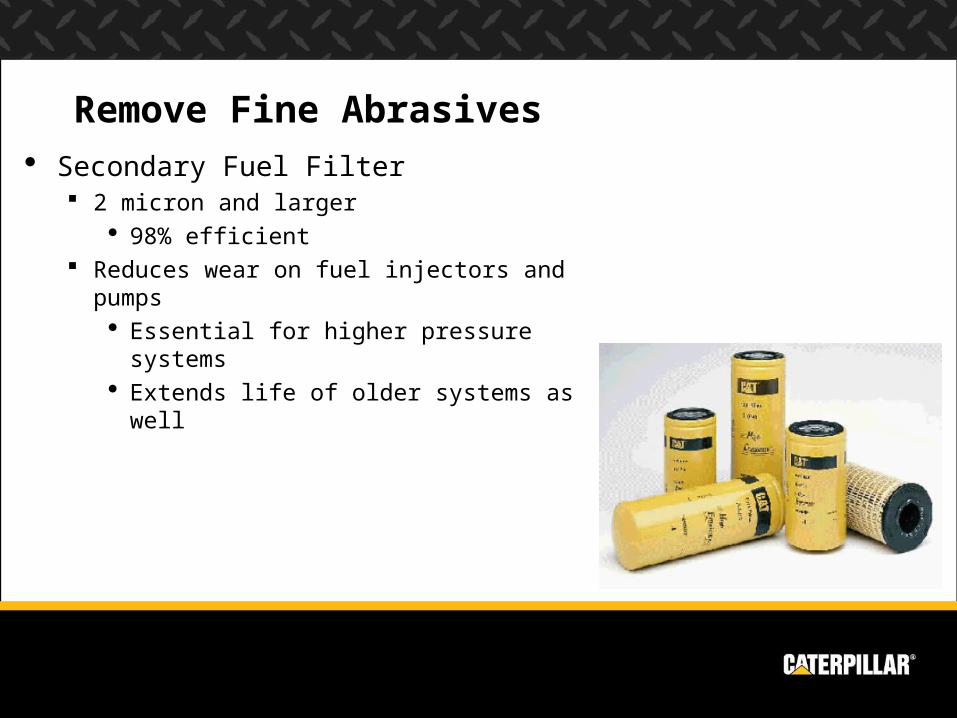
Remove Fine Abrasives
Secondary Fuel Filter 2 micron and larger
98% efficient Reduces wear on fuel injectors and pumps
Essential for higher pressure systems Extends life of older systems as well
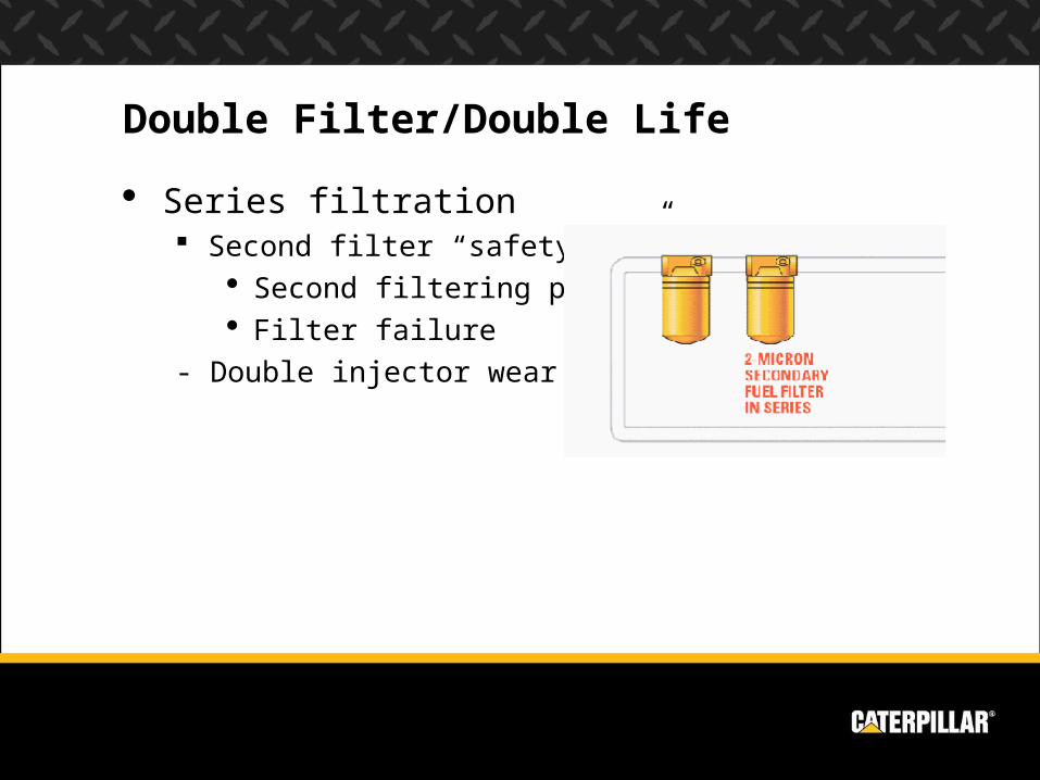
Double Filter/Double Life
Series filtration Second filter “safety net”
Second filtering pass Filter failure
- Double injector wear life
Engine Works & Wears Engine Wear Combustion Process Internal Components External Components Cooling System Lubrication System Fuel System Air System Electronics
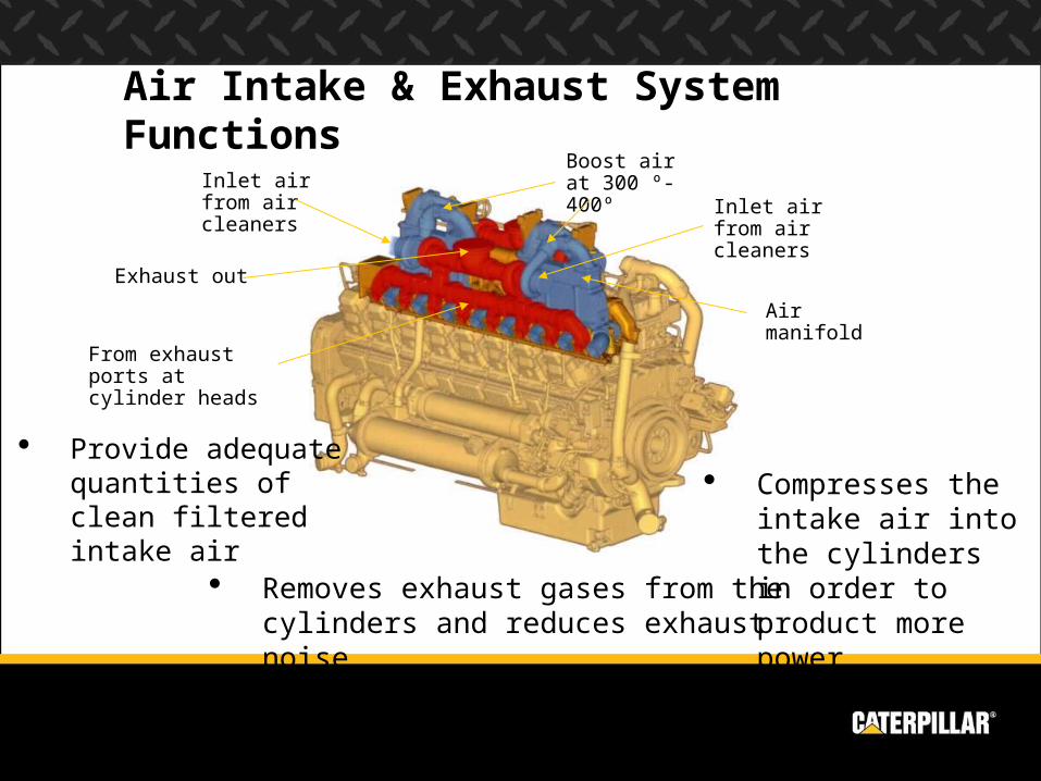
Air Intake & Exhaust System Functions
Compresses the intake air into the cylinders in order to product more power Removes exhaust gases from the
cylinders and reduces exhaust noise
Provide adequate quantities of clean filtered intake air
Inlet air from air cleaners
Exhaust out
Boost air at 300 º- 400º
Air manifold
Inlet air from air cleaners
From exhaust ports at cylinder heads
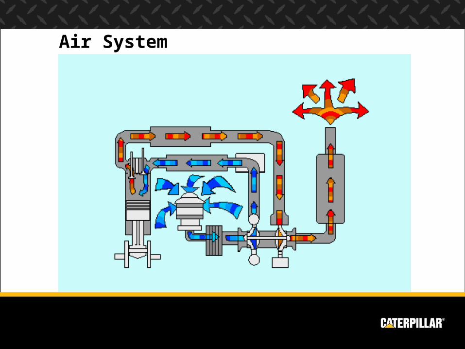
Air System
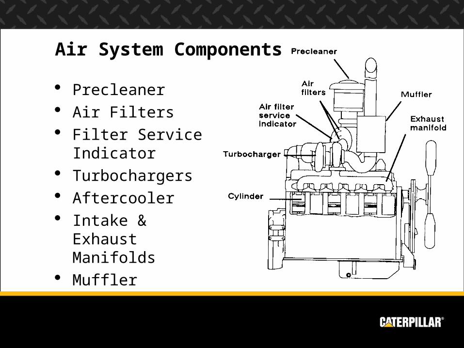
Precleaner Air Filters Filter Service
Indicator Turbochargers Aftercooler Intake & Exhaust
Manifolds Muffler
Air System Components
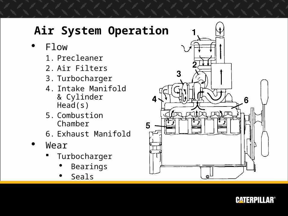
Air System Operation Flow
1. Precleaner2. Air Filters3. Turbocharger4. Intake Manifold &
Cylinder Head(s)5. Combustion
Chamber6. Exhaust Manifold
Wear Turbocharger
Bearings Seals
Air System Wear & Failure Causes
Single most common problem – dust ingestion Causes accelerated abrasive wear of piston rings & liners Most often caused by inlet leaks around flexible joints in
air inlet piping May also be caused by defective/damaged air filters, or
poor maintenance practices
Plugged air filters Turbo failures Coolant to air leaks in the aftercooler Hydraulic lock