Engine failure Jabiru, NT 11 February 2008 VH-VAZ Beech Aircraft Corporation 1900€¦ · ·...
43
ATSB TRANSPORT SAFETY REPORT Aviation Occurrence Investigation – AO-2008-008 Final Engine failure – Jabiru, NT – 11 February 2008 VH-VAZ Beech Aircraft Corporation 1900
Transcript of Engine failure Jabiru, NT 11 February 2008 VH-VAZ Beech Aircraft Corporation 1900€¦ · ·...

ATSB TRANSPORT SAFETY REPORT
Aviation Occurrence Investigation – AO-2008-008
Final
Engine failure – Jabiru, NT – 11 February 2008
VH-VAZ
Beech Aircraft Corporation 1900

- i -
ATSB TRANSPORT SAFETY REPORT
Aviation Occurrence Investigation
AO-2008-008
Final
Engine failure
Jabiru, NT – 11 February 2008
VH-VAZ
Beech Aircraft Corporation 1900
Released in accordance with section 25 of the Transport Safety Investigation Act 2003

- ii -
Published by: Australian Transport Safety Bureau
Postal address: PO Box 967. Civic Square ACT 2608
Office location: 62 Northbourne Ave, Canberra City, Australian Capital Territory, 2601
Telephone: 1800 020 616, from overseas +61 2 6257 4150
Accident and incident notification: 1800 011 034 (24 hours)
Facsimile: 02 6247 3117, from overseas +61 2 6247 3117
Email: [email protected]
Internet: www.atsb.gov.au
© Commonwealth of Australia 2009.
This work is copyright. In the interests of enhancing the value of the information contained in this
publication you may copy, download, display, print, reproduce and distribute this material in
unaltered form (retaining this notice). However, copyright in the material obtained from other
agencies, private individuals or organisations, belongs to those agencies, individuals or
organisations. Where you want to use their material you will need to contact them directly.
Subject to the provisions of the Copyright Act 1968, you must not make any other use of the
material in this publication unless you have the permission of the Australian Transport Safety
Bureau.
Please direct requests for further information or authorisation to:
Commonwealth Copyright Administration, Copyright Law Branch
Attorney-General’s Department, Robert Garran Offices, National Circuit, Barton, ACT 2600
www.ag.gov.au/cca
ISBN and formal report title: see ‘Document retrieval information’ on page iii

- iii -
DOCUMENT RETRIEVAL INFORMATION
Report No.
AO-2008-008
Publication date
15 July 2009
No. of pages
41
ISBN
978-1-921602-85-6
Publication title
Engine failure - Jabiru, NT - 11 February 2008 - VH-VAZ, Beech Aircraft Corporation 1900.
Prepared By
Australian Transport Safety Bureau
PO Box 967, Civic Square ACT 2608 Australia
www.atsb.gov.au
Reference Number
INFRA-09103
Acknowledgements
Figure 1: Courtesy of the operator.
Abstract
On 11 February 2008, at about 0720 Central Standard Time, following takeoff from runway 27 at
Jabiru Airport, NT, a Beech Aircraft Corporation 1900D, registered VH-VAZ, sustained an
auto-feather of the left propeller and subsequent left engine failure.
The aircraft was being operated on a charter flight to Darwin with two pilots and a passenger on board.
The pilots reported that, following the engine failure, they completed a single-engine circuit and
landing at Jabiru. Subsequent examination of the left engine revealed catastrophic internal damage to
the power section of the engine. The initiator of the damage was the release of a power turbine
second-stage blade. Metallurgical examination determined that the failure of the second-stage turbine
blade had occurred as a consequence of the initiation and growth of a high-cycle fatigue cracking
mechanism from the downstream trailing corner of the blade fir-tree root post. At the time of blade
fracture, approximately 25% of the root cross-section had been compromised by fatigue cracking.
The investigation found that during the most recent overhaul of the engine, the overhaul facility did not
comply with the engine manufacturer’s service bulletin regarding second-stage turbine blade
replacement. Consequently, outdated blades were installed.
- iv -
THE AUSTRALIAN TRANSPORT SAFETY BUREAU
The Australian Transport Safety Bureau (ATSB) is an operationally independent
multi-modal bureau within the Australian Government Department of
Infrastructure, Transport, Regional Development and Local Government. ATSB
investigations are independent of regulatory, operator or other external
organisations.
The ATSB is responsible for investigating accidents and other transport safety
matters involving civil aviation, marine and rail operations in Australia that fall
within Commonwealth jurisdiction, as well as participating in overseas
investigations involving Australian registered aircraft and ships. A primary concern
is the safety of commercial transport, with particular regard to fare-paying
passenger operations.
The ATSB performs its functions in accordance with the provisions of the
Transport Safety Investigation Act 2003 and Regulations and, where applicable,
relevant international agreements.
Purpose of safety investigations
The object of a safety investigation is to enhance safety. To reduce safety-related
risk, ATSB investigations determine and communicate the safety factors related to
the transport safety matter being investigated.
It is not the object of an investigation to determine blame or liability. However, an
investigation report must include factual material of sufficient weight to support the
analysis and findings. At all times the ATSB endeavours to balance the use of
material that could imply adverse comment with the need to properly explain what
happened, and why, in a fair and unbiased manner.
Developing safety action
Central to the ATSB’s investigation of transport safety matters is the early
identification of safety issues in the transport environment. The ATSB prefers to
encourage the relevant organisation(s) to proactively initiate safety action rather
than release formal recommendations. However, depending on the level of risk
associated with a safety issue and the extent of corrective action undertaken by the
relevant organisation, a recommendation may be issued either during or at the end
of an investigation.
The ATSB has decided that when safety recommendations are issued, they will
focus on clearly describing the safety issue of concern, rather than providing
instructions or opinions on the method of corrective action. As with equivalent
overseas organisations, the ATSB has no power to implement its recommendations.
It is a matter for the body to which an ATSB recommendation is directed (for
example the relevant regulator in consultation with industry) to assess the costs and
benefits of any particular means of addressing a safety issue.
About ATSB investigation reports: How investigation reports are organised and
definitions of terms used in ATSB reports, such as safety factor, contributing safety
factor and safety issue, are provided on the ATSB web site www.atsb.gov.au
- 1 -
FACTUAL INFORMATION
History of the flight
On 11 February 2008, at about 0720 Central Standard Time1, following takeoff
from runway 27 at Jabiru Airport, NT, a Beech Aircraft Corporation 1900D,
registered VH-VAZ, sustained an auto-feather of the left propeller and subsequent
left engine failure.
The aircraft was being operated on a charter flight to Darwin with two pilots and a
passenger on board. The pilots reported that, following the engine failure, they
completed a single-engine circuit and landing at Jabiru.
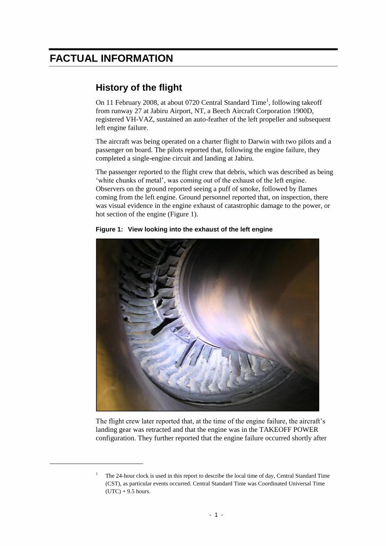
The passenger reported to the flight crew that debris, which was described as being
‘white chunks of metal’, was coming out of the exhaust of the left engine.
Observers on the ground reported seeing a puff of smoke, followed by flames
coming from the left engine. Ground personnel reported that, on inspection, there
was visual evidence in the engine exhaust of catastrophic damage to the power, or
hot section of the engine (Figure 1).
Figure 1: View looking into the exhaust of the left engine
The flight crew later reported that, at the time of the engine failure, the aircraft’s
landing gear was retracted and that the engine was in the TAKEOFF POWER
configuration. They further reported that the engine failure occurred shortly after
1 The 24-hour clock is used in this report to describe the local time of day, Central Standard Time
(CST), as particular events occurred. Central Standard Time was Coordinated Universal Time
(UTC) + 9.5 hours.
- 2 -
selecting the engine bleed air OPEN, and that it was preceded by a loud ‘banging’
noise, followed by a left yaw of the aircraft.
Subsequent analysis of the aircraft’s flight recorder data indicated that the engine
failure occurred about 20 seconds after takeoff, at about 600 ft above ground level
and at an indicated airspeed of 169 kts. The data indicated normal operation of the
engine prior to the occurrence.
The left engine was removed by the operator’s personnel and shipped to an
approved engine overhaul facility for disassembly and examination under the
supervision of the Australian Transport Safety Bureau (ATSB).
Engine disassembly
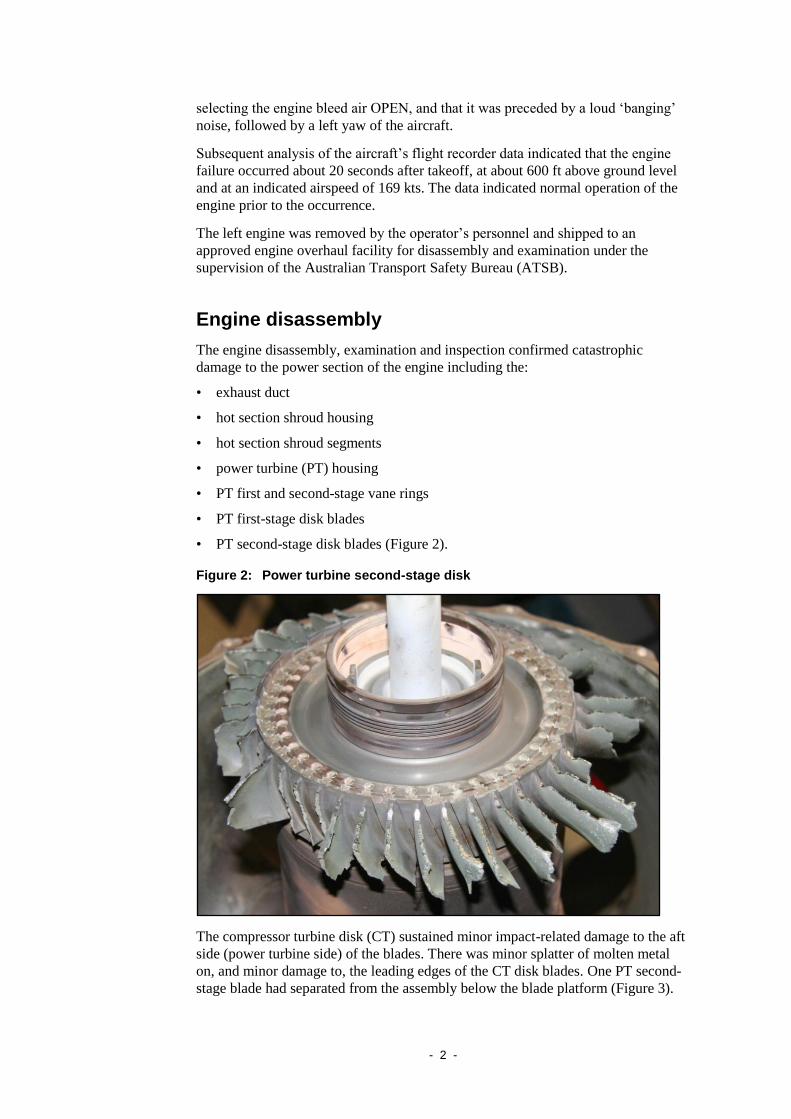
The engine disassembly, examination and inspection confirmed catastrophic
damage to the power section of the engine including the:
• exhaust duct
• hot section shroud housing
• hot section shroud segments
• power turbine (PT) housing
• PT first and second-stage vane rings
• PT first-stage disk blades
• PT second-stage disk blades (Figure 2).
Figure 2: Power turbine second-stage disk
The compressor turbine disk (CT) sustained minor impact-related damage to the aft
side (power turbine side) of the blades. There was minor splatter of molten metal
on, and minor damage to, the leading edges of the CT disk blades. One PT second-
stage blade had separated from the assembly below the blade platform (Figure 3).

- 3 -
Figure 3: Power turbine second-stage turbine blade close up
The components of the power section were sent to the ATSB’s technical facilities
for further examination. For further details concerning the metallurgical
examination and findings of that examination, refer to Attachment A.
Testing
The engine fuel pump and fuel control unit (FCU) were sent to the engine
manufacturer for testing under the supervision of the Transportation Safety Board
of Canada. That testing confirmed the normal operation of the fuel pump and FCU.
Engine history
The Pratt and Whitney Canada PT6A-67D engine, serial number 114239, was
installed in the aircraft in May 2007. The last overhaul of the power section was
completed by an overseas overhaul facility on 24 May 2005. At that time, the power
section had accumulated 18,058 hrs total time in service (TTIS), with 26,100 cycles
since new (CSN). On 8 February 2007, the time of the last maintenance on the
engine, the power section had accumulated 21,466.2 hrs TTIS, 29,054 CSN, 3,408
hrs time since overhaul (TSO) and 2,954 cycles since overhaul (CSO).
During the last overhaul of the power section on 24 May 2005, the part number
(PN) 3118563-01 PT second-stage blades were removed. Second-stage blades with

- 4 -
part number PN 3118353-012 were installed. The PN 3118353-01 blades had a
12,000 hour life limit. An entry by the overhaul facility in the engine maintenance
documentation incorrectly annotated compliance with Service Bulletin (SB)
14172R1, with their entry noting that there were 8,951 CSN and 6,049 cycles
remaining on the PN 3037313 serial number A00087CM disk at that time.
The engine manufacturer authorised the use of Avgas for a maximum of 150 hrs
between engine overhaul periods. The operator was asked about any possible use of
diesel or Avgas in the engine and responded:
Prior to entering ops with VA [operator abbreviation], no record existed of
such usage. From January 1st 2007 to 19th December 2007 the aircraft flew a
combined total of 4.5 hrs on Avgas according to our records, following supply
failure at one of the remote strips.
Significant engine maintenance items are noted below (Table 1).
Table 1: Significant engine logbook maintenance items3
The investigation could not determine the number of engines that may be in service
with the post-SB power turbine second-stage blades installed and compliance with
SB 14172R1 incorrectly annotated the affected engines’ maintenance
documentation.
2 The engine manufacturer advised that the pre SB14172 blades, PN 3118353-01, had not been
available for procurement since 1 September 1993.
3 All required 50/100 and 200 hourly intervals inspections were completed as required.
4 Power section total time in service.
Date Hours
TTIS4
Maintenance/inspections completed
8 February 2008 21,466 hrs 50/200 hr inspection, foreign object damage (FOD)
inspection and compressor wash.
14 December
2007
21,266 hrs 50/200 hr inspection, compressor FOD inspection
and wash.
22 October 2007 21,069 hrs 50/200 hr inspection, compressor FOD inspection
and wash.
16 July 2007 20,688 hrs 50/200 hr inspection, compressor FOD inspection
and wash.
9 May 2007 20,494 hrs Fuel nozzle replacement and borescope.
12 January 2007 20,211 hrs 50/200 hr inspection, compressor FOD inspection
and wash, fuel nozzle replacement and borescope.
23 November
2006
20,019 hrs Hot end inspection of CT vane assembly and disk,
calibration of engine temperature and torque
indicating systems.
- 5 -
Engine manufacturers advisories
The engine manufacturer’s SB14172R15 listed the replacement of PT rotor
balancing assemblies. It noted that the purpose of the bulletin was to reduce shroud
thickness variation, increase blade strength and improve blade tip clearances by
installing PN 3118563-01 PT second-stage blades. The new blades were made from
a different material, which had an allowance for final blade tip machining at the
disk assembly level and a cast to size shroud. Engine overhaul shops were directed
to re-identify the second-stage PT disks to PN 3118447-01 upon replacement.
Compliance with the SB was required when the engine was disassembled and
access was available to the necessary subassembly.
In September 1994, the engine manufacturer implemented a fleet retrofit program to
monetarily credit customers for the turbine blade replacement. The program was in
effect until 31 December 1998. The manufacturer implemented another program in
2004 for the same purpose. The engine manufacturer advised that the engine on this
aircraft was manufactured with post SB14172R1 PT second-stage blades installed
(PN 3118563-01 blades).
Engine manufacturer’s comments
The engine manufacturer was contacted and requested to provide information on the
application of SB14172R1 as outlined below.
• No mention of 'backwards modification' (reverting back to the older PN
3118353-01 blades, and whether or not it was authorised)
Response- There is no such instruction in the SB 14172 to revert back to pre-
configuration since [the manufacturer] introduced a product improvement to
increase engine reliability which requires embodiment of the SB upon access.
The pre SB14172 are required with recurrent periodic inspection per
Maintenance Manual (72-00-00 periodic inspection) to start as the blades
reach 1,500 hrs as opposed to starting at 4,000 hrs for the post SB14172. [the
manufacturer] has no records showing that the operator did such inspection
from 1,500 hrs.
• Clarify the engine manufacturers’ position regarding the issues of replacing
post-SB14172 blades into the PT disk during overhaul and the retirement times
of that particular blade.
Response-The requirement to replace is not just for Overhaul but rather any
time access is made available. SB 14003 doesn't make reference to the P/N
3118353-01 (Pre 14172) since the SB is required to be embodied due to its
code 5 embodiment requirement.
According to the manufacturer, a code 5 embodiment or category 56 was action
required when the engine was disassembled and access was available to the
necessary subassemblies (i.e. modules, accessories, components or build groups).
5 Original issue date 8 October 1993, revised 12 April 1996 and superseded by SB14259 under
revision No.4, 9 March 2005.
6 Included categories 1 through 10 with 1 being the highest priority and compliance before the next
flight required.

- 6 -
Engine condition trend monitoring
The operator was maintaining the engine using the engine manufacturer approved
engine condition trend monitoring (ECTM) system. The ECTM system required
pilots to fly the aircraft in cruise flight at stabilised speeds/temperatures and to
either manually record the engine parameters, or to have them recorded
electronically using a data logger. The aircraft did not have a data logger installed7.
The investigation reviewed the ECTM data from the operator for the engine from
1 July 2007 to 29 January 2008. The data indicated that on 24 January 2008, all
parameters were reading lower than the original baseline8 with a notation ‘need
more trend data’. The data recorded indicated that from 17 December 2007 to
4 January 2008 the engine ‘delta9’ fuel flow and inter-turbine temperature (ITT)
decreased below baseline values with the delta Ng10
above the baseline. After
4 January 2008, the delta ITT increased, with the other recorded values remaining
stable. A notation made on the records stated ‘same comments as last week will re-
base after torque gauge cleaned at 31 January 2008’. None of the notations
regarding ECTM data was recorded in the aircraft engine logbook.
Engine Condition Trend Monitoring raw data was also sourced from 3 March 2006
to 1 February 2008 and indicated that the data was taken at greatly varying
altitudes11
, outside air temperatures and airspeeds12
. The ECTM data did not note
any obvious anomalies of the engine parameters that would have indicated
impending failure.
Regarding large variations in altitude, the engine manufacturer’s training manual
recommended that:
Keeping the same flight profile minimizes scatter on the trend graph, it is
preferred to remain within the same altitude band (5,000′ band) from day to
day. Flight at many different altitudes (12,000 ft. to 25,000 ft.) will require
different engine loads for pressurizing and heating the cabin. These changes in
engine loads are not compensated for by the WebECTM program and will
cause scatter on the trend graphs.
7 Use of a data logger eliminated potential human error when recording information.
8 Recorded data was compared to the engine baseline parameters established when the engine was
new or recently overhauled. The baseline could be revised when it was clearly established that it
was set with incorrect values or flight conditions had changed significantly.
9 The difference between the actual engine parameter and the predicted engine mathematical model
parameter value.
10 Gas generator speed.
11 Varying from a minimum of 2,300 ft pressure altitude to a maximum of 25,000 ft pressure
altitude.
12 Indicated airspeeds from a minimum of 160 to 230 kts.
- 7 -
ANALYSIS
The failure of the left engine following takeoff was the result of the catastrophic
failure of the engine hot section and specifically the power turbine (PT) section.
The flight crew correctly identified the problem engine and took timely and
appropriate action to return to the airport and complete an uneventful single-engine
landing. There were no indicators to the flight crew or to maintenance personnel of
the impending failure of the PT section components.
The engine condition trend monitoring (ECTM) system data that was collected for
the aircraft’s engines was documented at largely varying pressure altitudes, outside
air temperatures and airspeeds, making the data unreliable. Regardless, it did not
appear that the impending failure of the PT blade would have been detectable using
the ECTM system.
The engine manufacturer advised that the engine was manufactured with post
Service Bulletin (SB) 14172R1 power turbine second-stage blades installed (part
number (PN) 3118563-01 blades). During the subsequent overhaul of the engine by
an overseas overhaul facility, PN 3118353-01 second-stage PT blades were
installed, and compliance with SB 14172R1 was incorrectly annotated in the
engine’s documentation. Advice from the engine manufacturer indicated that the
PN 3118353-01 second-stage PT blades should not have been installed in the
engine, as they were the subject of an earlier, fleet-wide engine upgrade campaign.
The involvement of the overseas overhaul facility contributed to the inability of the
investigation to establish why the pre- SB 14172R1 blades were installed during the
May 2005 engine overhaul, and the reason for the incorrect annotation in the
engine’s documentation.
However, the older PN 3118353-01 PT blades, if installed, were subject to a
recurrent periodic 1,500 hr inspection. A review of the engine’s maintenance
documentation did not show any evidence that those recurrent inspections had been
carried out. Technicians scheduling engine maintenance subsequent to the May
2005 overhaul may have been misled by the incorrect annotation of the engine’s
compliance with SB 14172R1. The effect would have been that the technicians
would have interpreted that the routine inspection of the blades was not yet
required.

- 8 -

- 9 -
FINDINGS
Following takeoff, the aircraft’s left engine sustained a catastrophic failure of the
power turbine (PT) section resulting in a complete loss of engine power from that
engine.
From the evidence available, the following findings are made with respect to the
engine failure involving VH-VAZ and should not be read as apportioning blame or
liability to any particular organisation or individual.
Contributing safety factors
• During operation, a blade on the second-stage PT disk separated, resulting in
substantial damage to the engine hot section.
Other safety factors
• During engine overhaul on 24 May 2005, the part number 3118353-01 second-
stage PT blades were installed, contrary to a fleet-wide engine upgrade
campaign and Service Bulletin (SB) 14172R1, and maintenance documentation
incorrectly annotated as complying with SB 14172R1. As a result, the part
number 3118353-01 second-stage PT blades were not inspected at the required
periodic interval of 1,500 hrs.
• Engine condition trend monitoring data was being collected or recorded in a
manner that was not recommended by the engine manufacturer.
Other key findings
• The flight crew correctly identified the problem engine and took timely and
appropriate action to return to the airport and complete a single-engine landing.
• There were no indicators to the flight crew or to maintenance personnel of the
impending failure of the PT section components.


11
APPENDIX A: TECHNICAL ANALYSIS REPORT
ATSB TECHNICAL ANALYSIS REPORT
AO-2008-008
Engineering Failure Analysis of Turboprop
Engine Components
Pratt & Whitney Canada, PT6A-67D
Beech Aircraft Corporation 1900D
VH-VAZ, 11 February 2008
Released in accordance with section 25 of the Transport Safety Investigation Act 2003

– 12 –
SUMMARY
On 11 February 2008, a Beech 1900D aircraft (registered VH-VAZ), operating a
charter flight from Jabiru, NT to Darwin, NT, sustained the in-flight failure of the
left engine shortly after departure from Jabiru airport.
The failed engine, a Pratt & Whitney Canada PT6A-67D turboprop, had operated
for approximately 21,466 hours since new, and 3,408 hours since the last overhaul.
Disassembly and laboratory examination determined that the engine failure was
precipitated by the fracture and release of a single blade from the second-stage
power turbine rotor; subsequently producing gross mechanical interference within
the turbine confines and the forced failure and damage to the adjacent rotating and
stationary components.
Metallurgical examination determined that failure of the second-stage turbine blade
had occurred as a consequence of the initiation and growth of a high-cycle fatigue
cracking mechanism from the downstream trailing corner of the blade fir-tree root
post. At the time of blade fracture, approximately 25% of the root cross-section had
been compromised by fatigue cracking.
While the fatigue crack origin was clearly identified, the metallurgical examination
found no direct evidence of contributory defects or damage at that location. The
possibility remains however, that non-metallic inclusions or surface features similar
to those that were identified in the origin area, may have been present in some form
at the origin itself; thus predisposing the blade to premature fatigue cracking from
the location observed. The loss of the corresponding fracture surface with the outer
section of the turbine blade hindered any further investigation in that respect.
None of the other blades from the second-stage power turbine rotor showed any
external indication of cracking or potentially detrimental physical features.
– 13 –
FACTUAL INFORMATION
Introduction
On 11 February 2008 at about 0720 Central Standard Time (2150 UTC, 10
February), following takeoff from runway 27 at Jabiru Airport, NT, a Beech
Aircraft Corporation 1900D, registered VH-VAZ, sustained an in-flight failure of
the left engine and the subsequent auto-feathering of the left propeller. The flight
crew reported that the failure was characterised by a loud ‘banging’ noise and an
associated left yaw of the aircraft. The sole passenger aboard the aircraft described
‘white chunks of metal’ coming from the left engine exhaust, while observers on
the ground noted smoke and flames coming from the left engine. Following the
engine failure, the flight crew completed a single circuit of the aerodrome and a
landing back at Jabiru.
Preliminary inspections of the engine by ground personnel revealed evidence of
extensive damage within the engine turbine stages. As a result, the engine was
removed from the aircraft and shipped to an approved overhaul facility for
disassembly and examination under the supervision of investigators from the
Australian Transport Safety Bureau (ATSB).
The engine examination confirmed extensive mechanical damage to the turbine
(power) section of the engine, including the:
• exhaust duct
• hot-section shroud housing
• hot-section shroud segments
• power turbine housing
• power turbine first and second stage vane rings
• first-stage power turbine disk blades
• second-stage power turbine disk blades.
Scope of the examination
To assist in the analysis of the damage sustained by the engine and the
identification of factors that had contributed to the in-flight failure, the following
engine components were received at the ATSB’s Canberra laboratories, after
completion of the engine disassembly:
• Power turbine stator housing, with damaged power turbine interstage stator
assembly in-situ,
• fragmented power turbine vane ring and air seal,
• compressor turbine disk (P/N: 3040911, S/N: 75A096) and installed blades,
• first-stage power turbine disk (P/N: 3037312 N, S/N: A0008NH7) and installed
blades (P/N: 3120112-01),
• second-stage power turbine disk (P/N: 3037313L, S/N: A00087CM) and blades
(three removed),

– 14 –
• three blades (P/N: 3118353-01) removed from second-stage power turbine disk.
Figure A1 (Attachment A) presents a cross-sectional view of the PT6A-67D turbine
(hot) section, identifying and illustrating the correlation of the components
examined.
Engine details
The PWC PT6A-67D turboprop engine was a light-weight, free turbine powerplant,
employing a five-stage combined axial/centrifugal compressor, with a single-stage
axial compressor turbine and an independent two-stage axial power turbine driving
the propeller via a reduction gearbox. The engine was nominally rated at 900 kW /
1,200 shp13
maximum continuous output power.
At the time of the last workshop maintenance visit on 8 February 2008, the engine
power section module (S/N: PCE 114386) had operated for 21,466 hours since new
(TSN) and 3,408 hours since the last overhaul (TSO), which was conducted in May
2005. Overhaul records showed that both first and second-stage power turbine
blades (P/N: 3120112-01 and 3118353-01 respectively) were renewed at that time.
Histories of other non-lifed14
turbine section components (e.g. stator assemblies)
were not available from the maintenance documentation examined.
The last engine hot-section inspection (HSI15
) was completed on 23 November
2006, at an engine TSN of 20,019 hours and TSO of 1,961 hours. Engine HSI’s
were scheduled for intervals not exceeding 2,000 hours of operation.
Component examination
Power turbine stator housing and interstage stator vane ring
The power turbine stator housing and interstage stator assembly were received as a
unit (Figure 1), with the degree of distortion sustained by the vane ring preventing
its free removal from the housing. Internally, the housing presented severe
disruption and break-up of the vane ring around the rotational plane of both first
and second-stage power turbine disks (Figure 2). The vane ring elements showed
prominent impact and metal loss from the trailing edges, together with a
pronounced rotational (torsional) and radial distortion of the vane set in the
direction of turbine rotation. The stator air seal had separated from the ring inner
platform as a result of the vane element distortion. The vane set also showed a
degree of axial out-of-plane displacement toward the inner ends – the displacement
presenting as a ‘dishing’ of the vane set in the upstream direction. Evidence of
localised contact between the vane set inner platform ends and the upstream ends of
the second-stage power turbine disk was also noted around much of the diameter –
producing a machining metal-loss effect.
Externally, the turbine stator housing rear flange mounting bolt holes showed
circumferential distortion – consistent with the torsional forces that produced the
13 Shaft Horse Power – power available at the engine output.
14 Non-lifed components are typically maintained ‘on condition’, whereby their suitability for
continued service is assessed during each periodic inspection.
15 A prescribed periodic inspection of the engine combustion and turbine components.

– 15 –
ductile shear failure of the flange bolts observed during the engine disassembly. The
T516
bus bar elements also showed a level of distortion and displacement, with the
probe wiring partially severed at the bifurcation and the probes presenting some
debris impact damage. The turbine casing had fully contained the liberated internal
debris, with no observed evidence of perforation or fracture.
Figure A1: Power turbine stator housing (down-stream end upward)
Figure A2: Disruption of the vane ring along the plane of rotation of the
second-stage power turbine disk
16 The T5 bus connects the T5 thermocouple probes that measure the interstage turbine temperatures
(ITT).

– 16 –
Power turbine stator ring
The first-stage power turbine stator ring had sustained extensive structural break-up,
with multiple fractures through the vanes and outer shroud sections (Figure A3).
Five main ring segments and many smaller fragments were removed from the
engine, with the interstage baffle plates separated from the stator ring bore. Visually
and under the stereomicroscope, all principal fracture surfaces exhibited similar
irregular and lightly oxidised characteristics – consistent with the fractures
occurring during the breakdown event. Some evidence of pre-existing cracking was
noted at the recess corners within the outer ring (Figure A4), however none of the
cracks showed features suggesting their direct contribution to the break-up of the
ring structure. The vane aerofoil sections, although damaged from the breakdown
event, did not show any other evidence of advanced service-related degradation.
Figure A3: Main power turbine stator ring sections – as received
Figure A4: Suspected prior cracking of stator ring – between arrows

– 17 –
Compressor turbine disk and blades
The engine compressor turbine disk and blade-set presented comparatively low
levels of mechanical damage, when compared against the downstream turbine
components. The leading edges and tips of all blades showed only light debris
impingement effects and adherent products (Figure A5). The blade trailing edges,
around approximately one-half of the disk circumference, showed localised impact,
deformation and edge breakage at the mid-span position (Figure A6). The regularity
and form of the damage suggested a hard-body foreign object impact mechanism
(Figure 7), with the absence of similar leading-edge damage suggesting the ingress
of the material from a downstream location.
The downstream face of the compressor turbine disk showed evidence of light
rotational contact against the stationary outer periphery of the interstage baffle or
the inner rim of the power turbine stator ring.
Figure A5: Upstream face of the engine compressor turbine disk

– 18 –
Figure A6: Downstream face – compressor turbine disk
Figure A7: Suspected hard-object impact damage to compressor turbine blade
trailing edges (arrowed)
– 19 –
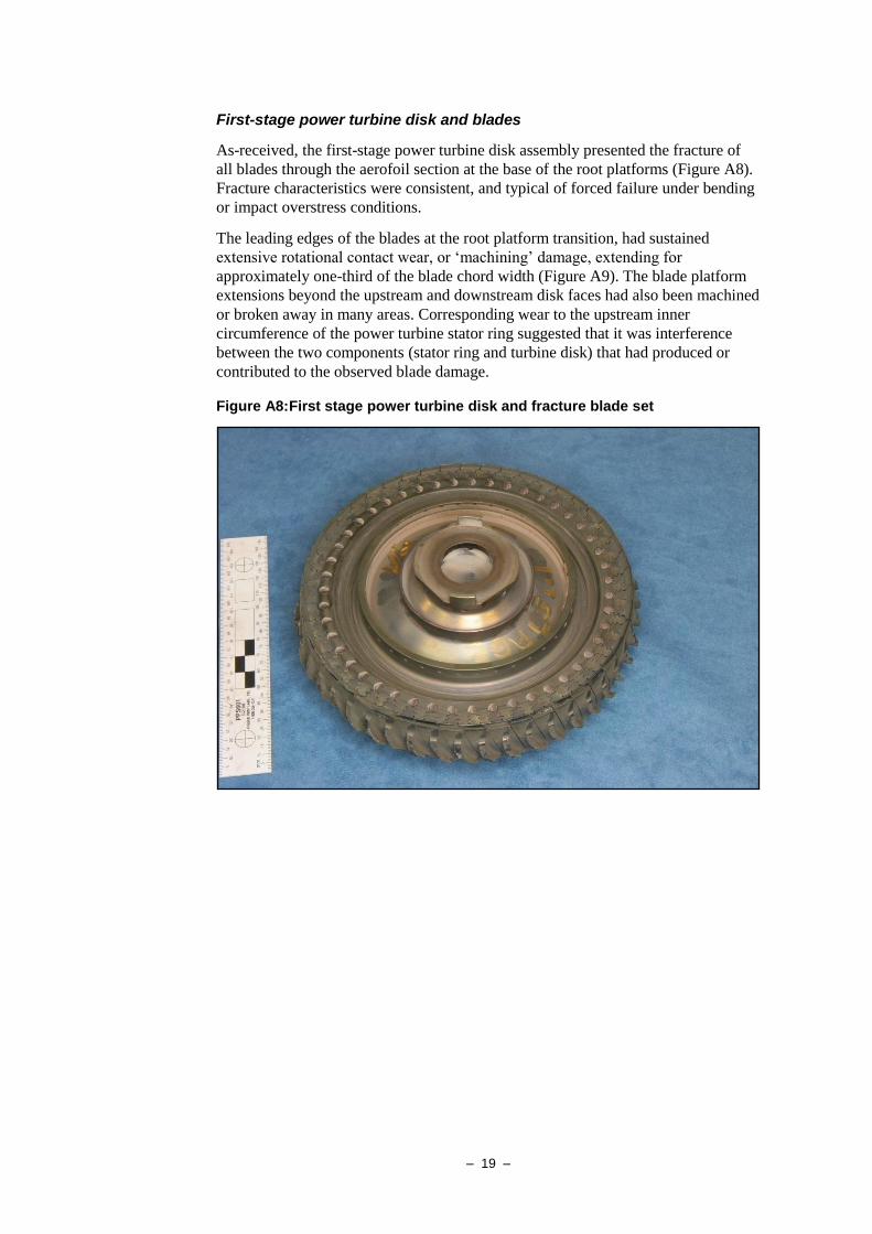
First-stage power turbine disk and blades
As-received, the first-stage power turbine disk assembly presented the fracture of
all blades through the aerofoil section at the base of the root platforms (Figure A8).
Fracture characteristics were consistent, and typical of forced failure under bending
or impact overstress conditions.
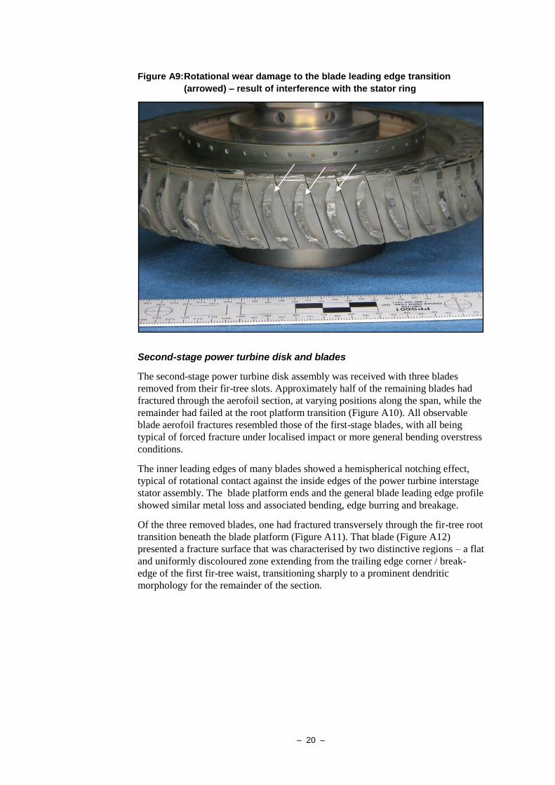
The leading edges of the blades at the root platform transition, had sustained
extensive rotational contact wear, or ‘machining’ damage, extending for
approximately one-third of the blade chord width (Figure A9). The blade platform
extensions beyond the upstream and downstream disk faces had also been machined
or broken away in many areas. Corresponding wear to the upstream inner
circumference of the power turbine stator ring suggested that it was interference
between the two components (stator ring and turbine disk) that had produced or
contributed to the observed blade damage.
Figure A8: First stage power turbine disk and fracture blade set
– 20 –
Figure A9: Rotational wear damage to the blade leading edge transition
(arrowed) – result of interference with the stator ring
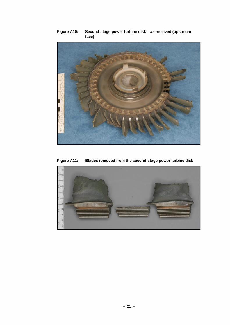
Second-stage power turbine disk and blades
The second-stage power turbine disk assembly was received with three blades
removed from their fir-tree slots. Approximately half of the remaining blades had
fractured through the aerofoil section, at varying positions along the span, while the
remainder had failed at the root platform transition (Figure A10). All observable
blade aerofoil fractures resembled those of the first-stage blades, with all being
typical of forced fracture under localised impact or more general bending overstress
conditions.
The inner leading edges of many blades showed a hemispherical notching effect,
typical of rotational contact against the inside edges of the power turbine interstage
stator assembly. The blade platform ends and the general blade leading edge profile
showed similar metal loss and associated bending, edge burring and breakage.
Of the three removed blades, one had fractured transversely through the fir-tree root
transition beneath the blade platform (Figure A11). That blade (Figure A12)
presented a fracture surface that was characterised by two distinctive regions – a flat
and uniformly discoloured zone extending from the trailing edge corner / break-
edge of the first fir-tree waist, transitioning sharply to a prominent dendritic
morphology for the remainder of the section.
– 21 –
Figure A10: Second-stage power turbine disk – as received (upstream
face)
Figure A11: Blades removed from the second-stage power turbine disk

– 22 –
Figure A12: Fracture surface regions from the sub-platform failed blade
Blade examination – second-stage power turbine
The single fractured second-stage power turbine blade that exhibited mixed-mode
fracture morphology was the subject of further detailed study to characterise the
fracture mechanisms. The liberated sections of the blade above the plane of fracture
were not recovered amongst the debris removed from the engine, and as such, the
part number of the failed blade could not be verified. However, general visual and
dimensional comparisons against the two neighbouring blades showed no evidence
that the particular failed blade was of a different form or characteristics that the
remainder of the installed items (P/N: 3118353-01).
Fractography
The region of comparatively flat, transverse fracture at the root trailing corner
extended for approximately 12.4 mm chord-wise and for 4.8mm in a through-
thickness orientation (Figure A12). Although stained and discoloured, the surface
detail in the corner region was moderately well-preserved, and under low-power
microscopy, presented curved, concentric fatigue crack progression markings. The
transition to coarse dendritic fracture occurred abruptly at the limit of fatigue
cracking, with the remainder of the fracture being typical of ductile overstress
failure in cast nickel-superalloy components.
Close study of the fracture morphology at the section corner revealed a
hemispherical surface sub-zone of bright crack progression markings, surrounding
an irregular darker feature (Figure A13). The zone was located on the root trailing
edge, immediately adjacent to the corner break-edge transition to the blade trailing
edge end (Figure A14).

– 23 –
Figure A13: Corner region at the origin of fatigue cracking (arrowed)
Figure A14: Location and orientation of fatigue crack origin (enclosed area
represented in Figure A13)

– 24 –
Electron microscopy
Scanning electron microscopy (SEM) techniques were employed to further examine
and characterise the fatigue crack origin and surrounds. Although somewhat
smeared and damaged, the surfaces around the origin showed evidence of the
typical concentric radiating striations associated with high-cycle fatigue (HCF17
)
crack growth (Figure A15). Multiple intersecting planes of cracking were evident
across the surface – likely representing the underlying grain structure of the blade
material.
The atomic number contrast provided by back-scattered electron imaging (BSE) of
the crack origin (Figure A16) showed no marked compositional variations within
the region, aside from random surface accumulations of foreign light-element
matter. The electron microscopy did not show any evidence of mechanical damage,
tool marks or other localised physical features associated with, or adjacent to the
origin region.
Figure A15: Low magnification SEM image of the fatigue crack origin
(arrowed) and surrounds
17 A mode of fatigue crack propagation where the dominant cyclic stress environment is a high-
frequency vibration, oscillation or resonance.

– 25 –
Figure A16: Fatigue crack origin – BSE image
X-ray imagery
Energy-dispersive x-ray mapping was carried out across the origin region depicted
in Figure A16. Aside from the visually apparent accumulations of surface matter
(characterised as silicon or carbon based contaminants), there was no clear evidence
of any entrained material with a compositional base that was significantly different
to the bulk blade alloy.
Metallography
A sample removed from the fractured blade root was mounted and prepared to
allow the examination of multiple parallel sections inward from the end face
towards the centre of the fatigue origin region. Prior to mounting, the origin area
was measured under the SEM to provide a datum against which the position of the
prepared surfaces could be related (Figure A17).
At low magnifications, the blade root material displayed a coarse dendritic
microstructure, characterised by a semi-continuous network of an interdendritic
second phase (Figure A18). At higher optical and SEM magnifications, the
interdendritic network showed a skeletal, plate like morphology, typical of
topologically close-packed (TCP) phases such as Laves phase (Figure A19),
surrounding the dendrites of very fine cuboidal gamma-prime (γʹ) precipitate within
a solid-solution gamma (γ) matrix (Figure 20).

– 26 –
Figure A17: Dimensional position of the fatigue crack origin region with
reference to the downstream (trailing) end face of the blade
Figure A18: Blade root microstructure – interdendritic network of Laves
phase, within a gamma, gamma-prime matrix
– 27 –
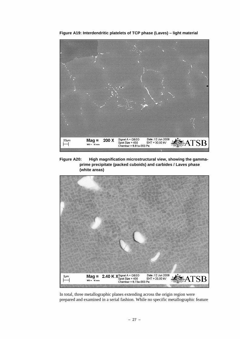
Figure A19: Interdendritic platelets of TCP phase (Laves) – light material
Figure A20: High magnification microstructural view, showing the gamma-
prime precipitate (packed cuboids) and carbides / Laves phase
(white areas)
In total, three metallographic planes extending across the origin region were
prepared and examined in a serial fashion. While no specific metallographic feature
– 28 –
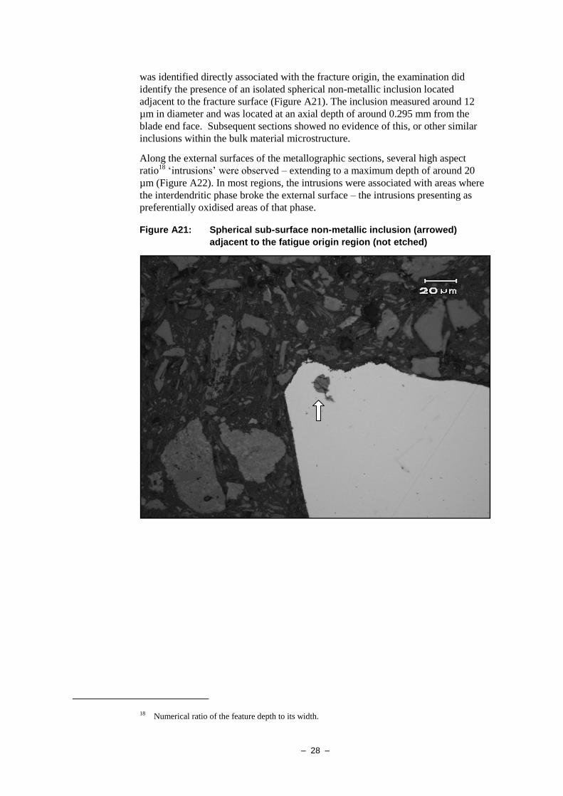
was identified directly associated with the fracture origin, the examination did
identify the presence of an isolated spherical non-metallic inclusion located
adjacent to the fracture surface (Figure A21). The inclusion measured around 12
µm in diameter and was located at an axial depth of around 0.295 mm from the
blade end face. Subsequent sections showed no evidence of this, or other similar
inclusions within the bulk material microstructure.
Along the external surfaces of the metallographic sections, several high aspect
ratio18
‘intrusions’ were observed – extending to a maximum depth of around 20
µm (Figure A22). In most regions, the intrusions were associated with areas where
the interdendritic phase broke the external surface – the intrusions presenting as
preferentially oxidised areas of that phase.
Figure A21: Spherical sub-surface non-metallic inclusion (arrowed)
adjacent to the fatigue origin region (not etched)
18 Numerical ratio of the feature depth to its width.

– 29 –
Figure A22: Intrusive surface feature (arrowed) – appears as oxidised
second phase (etched in Kalling’s reagent)
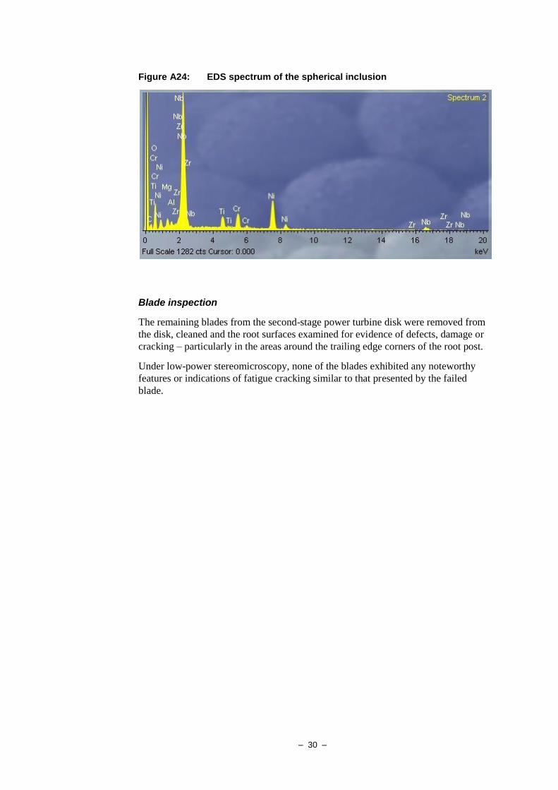
Micro-analysis
Energy-dispersive x-ray spectroscopy (EDS), conducted on the prepared
metallographic sections under the SEM, provided a qualitative indication of the
elemental composition of the base metal alloy and the non-metallic inclusion
observed microscopically. The base blade alloy presented as a nickel-based
superalloy of chromium, molybdenum, aluminium and titanium (Figure A23). The
inclusion was predominantly niobium rich, with nickel, oxygen, aluminium,
magnesium and zirconium sub-peaks (Figure A24).
Figure A23: EDS spectrum of the blade base metal alloy
– 30 –
Figure A24: EDS spectrum of the spherical inclusion
Blade inspection
The remaining blades from the second-stage power turbine disk were removed from
the disk, cleaned and the root surfaces examined for evidence of defects, damage or
cracking – particularly in the areas around the trailing edge corners of the root post.
Under low-power stereomicroscopy, none of the blades exhibited any noteworthy
features or indications of fatigue cracking similar to that presented by the failed
blade.

– 31 –
ANALYSIS
Engine failure
From the observations made during the engine disassembly and subsequent
laboratory examination, it was evident that the mechanical breakdown and failure of
the engine had been precipitated by the fracture and separation of a single blade
from the engine’s second-stage power turbine rotor. The gross mechanical
interference caused by the blade releasing into the confines of the turbine section,
together with the resultant imbalance of the turbine wheel, had produced the
subsequent forced failure of many other second-stage turbine blades and the
generation of a large quantity of energetic debris. Although unusual in the sense
that it required material movement against the gas flow path, it was probable that
some of that debris had moved upstream into the rotational space occupied by the
stage-one power turbine rotor, where it initiated the cascading forced failure of the
blades from that stage. Upstream displacement of the interstage stator components
to a point where interference occurred with the first-stage power turbine rotor was
also a potential contributor. Failure and break-up of the power turbine stator
assembly was consistent with the loads sustained during the multiple likely impacts
with the stage-one turbine blade debris.
Second-stage power turbine blade failure
Fracture of the stage-two power turbine blade in question had occurred from
beneath the transition platform between aerofoil and fir-tree root sections. A large
and well defined area of prior cracking attested to the initiation and growth of a
high-cycle fatigue cracking mechanism from the downstream trailing corner of the
root post. Fatigue cracking had transitioned to overstress rupture at a loss of
approximately 25% of the original cross-section.
Optical and electron microscopy confirmed the origin of the blade fatigue cracking
to lie adjacent to the corner break-edge region, with a small, semi-elliptical region
of crack development radiating into the section from a point approximately 0.5 mm
from the blade end face datum. The origin exhibited no evidence of mechanical
damage or other discontinuity, and metallography, EDS micro-analysis and x-ray
mapping failed to identify the presence of any anomalous metallurgical features that
could be directly associated with the point of crack initiation. A single isolated non-
metallic inclusion, probably entrained during the blade casting process, was
identified near the fatigue origin, however there was no evidence to associate that
feature with the cracking sustained.
Microstructurally, the bulk material presented the expected γ-γʹ constituents typical
of high-temperature superalloys. There was no evidence of creep voiding or
microstructural degradation associated with sustained or transient over-temperature
operation. The presence of an interdendritic TCP second phase (suspected as Laves)
was, however, considered suboptimal from a fatigue and oxidation resistance
perspective.

– 32 –

– 33 –
FINDINGS
The following statements are a summary of the substantiated findings made during
the progress of the engine and component examination.
• Failure of the PT6A-67D engine was consistent with the mechanical disruption
and breakage of componentry with the power-turbine section of the engine.
• The turbine section damage had been initiated by the fracture and liberation of a
single blade from the second-stage power turbine rotor.
• Fracture of the turbine blade had resulted from the propagation of a high-cycle
fatigue cracking mechanism through approximately 25% of the blade fir-tree
root post, followed by the overstress rupture of the remaining section under
service dynamic loads.
• Fatigue cracking originated from a point adjacent to the downstream trailing
root post corner.
• There was no evidence of gross manufacturing deficiencies within the blade
microstructure at the fatigue crack origin.
• There was no evidence of tool marks, machining damage or other mechanical
damage at the fatigue crack origin.
• The second-stage power turbine blades were replaced with new items during the
last engine overhaul.
• The second-stage power turbine blades had operated for approximately 3,400
hours since replacement.
• The last engine hot-section inspection had been carried out approximately 1,450
operating hours prior to the engine failure.
While the examination did not identify any direct evidence of a mechanism or
feature that had produced or contributed to the initiation of fatigue cracking from
the blade root, it remains possible that an isolated casting anomaly similar to the
observed inclusion or intrusion features, had acted to reduce the fatigue endurance
of the failed component to a point where it became susceptible to failure under
normal operating conditions and timeframes.

– 34 –

– 35 –
ATTACHMENT A
Figure A1A: Cross-sectional illustration of the PT6A-67D turbine section

– 36 –

– 37 –
APPENDIX B : SOURCES AND SUBMISSIONS
Sources of information
The sources of information for the investigation included the:
• flight crew of VH-VAZ
• operator of VH-VAZ
• owner of VH-VAZ
• engine manufacturer
• aircraft and engine historical documentation.
Submissions
Under Part 4, Division 2 (Investigation Reports), Section 26 of the Transport Safety
Investigation Act 2003, the Executive Director may provide a draft report, on a
confidential basis, to any person whom the Executive Director considers
appropriate. Section 26 (1) (a) of the Act allows a person receiving a draft report to
make submissions to the Executive Director about the draft report.
A draft of this report was provided to the Civil Aviation Safety Authority, the South
African Civil Aviation Authority, the Transportation Safety Board of Canada, the
National Transportation Safety Board, the engine overhaul facility, the aircraft
operator, the aircraft owner and the engine manufacturer.
A submissions was received from the engine overhaul facility. The submission was
reviewed and where considered appropriate, the text of the report was amended
accordingly.