Engine Control Systems for Industrial Engines - Altronic Inc
12
Engine Control Systems for Industrial Engines
Transcript of Engine Control Systems for Industrial Engines - Altronic Inc

Engine Control Systems
for Industrial Engines

All rights reserved© ALTRONIC, INC 2009AEC-C 9-09
2
Altronic Engine Control Systems
CONTENTS
Altronic Engine Control Systems
Contents and Overview ..................................................................................... 2
Air/Fuel Ratio Control Systems and Accessories
EPC-50 Air/Fuel Ratio Control and Monitoring System ......................................... 3
EPC-110/120 Air/Fuel Ratio Control and Monitoring Systems .............................. 4
EPC-100E Advanced Air/Fuel Ratio Control System ............................................ 5
EPC-150 Lean Burn Engine Air/Fuel Ratio Control System ................................... 6
690-Series Control Valves/Stepper Controller ...................................................... 7
EPC-200C Fuel-Admitted Engine Performance Controller .................................... 8
Speed Governing and Fuel Control Systems
AGV5 Smart Gas Control Valve .......................................................................... 9
GOV10/50 Gas Engine Governing Systems ....................................................... 10
Engine Starting Systems
SaveAir™ Electronic Air Start System .............................................................. 11
Each make and model of natural gas
engine has its own unique set of starting
and performance requirements. For well
over twenty years, Altronic has met these
individual needs with high-quality, easily-
installed and understood control systems
for small and large gas engines alike.
Constant attention to product develop-
ment and manufacturing quality prompt
users around the world to turn to Altronic
control products to meet their natural gas
engine air/fuel ratio control, speed gover-
ning, and starting system requirements.
The pages that follow will give you a solid
introduction to the range and specific ca-
pabilities of each member of the Altronic
engine control product line. Additional
details, including application, installa-
tion, and operating information associa-
ted with each system, can be found on
the web at www.altronicinc.com. Your
local authorized Altronic Distributor and
Dealer, Regional Manager, and Altronic
factory sales and service staff are also
available to address your specific applica-
tion questions
Insuring Performance and Compliance: Altronic Control Systems for Natural Gas-Fueled Engines
CERTIFIED FOR USE IN HAZARDOUS LOCATIONSNOTE: Most, but not all, Altronic
digital instruments and controls in
this catalog are CSA certified and
compliant with the appropriate
CE/ATEX regulations. Check each
product listing for certification and
hazardous area classification.

All rights reserved© ALTRONIC, INC 2009AEC-C 9-09
3
Air/Fuel Ratio Control Systems and Accessories
CERTIFIEDCLASS 1DIV. 2 GROUPS C & D
EPC-50 Air/fuel Ratio Control for Low-Horsepower Carbureted Natural Gas-Fueled Engines The Altronic EPC-50 is an air/fuel ratio
controller designed for use on low-horse-
power, carbu-
reted natural
gas-fueled
engines. It em-
ploys micropro-
cessor technol-
ogy, allowing
for a high level
of sophistication in control
strategy, ease of configuration
and diagnostic capability. The
EPC-50 and associated small
engine-specific control valves
are designed for use on engines operat-
ing at or near a stoichiometric air/fuel
ratio and is ideally suited for application
with 3-way catalytic converters. While it
is designed to be mounted in the engine/
compressor control panel, a NEMA 3R
housing (720004-1) is also available as
an alternative mounting option.
The single control output of the EPC-50
allows for its use on any engine appli-
cation incorporating a single fuel gas
regulator. An oxygen sensor is used in the
exhaust stream to sense O2 content, and
a thermocouple input signals when proper
exhaust temperature has been reached
to allow for accurate sensor operation.
A system fuel control valve installed in
the fuel line to the carburetor is pre-
cisely adjusted by a stepper-motor under
microprocessor control to maintain the
correct O2 content in the exhaust. The de-
sired air/fuel ratio can be easily adjusted
by changing the control target voltages
through the sealed membrane keypad or
through the use of a PC. The EPC-50 also
incorporates a thermocouple input and a
dedicated output for implementation of
catalyst over-temperature protection. A
second digital output is available for use
as an alarm for diagnostics or uncon-
trolled operation.
The EPC-50 has an alphanumeric LCD
display showing the target voltage, sensor
voltage, operating temperature, stepper
motor position and diagnostic information.
Power requirement is 24 (12–30) VDC,
1 amp. In remote areas, power can be
provided by the Altronic 24VDC Alternator
Power Package. Refer to Altronic Form ALT.
� Designed specifically for use on low-horsepower stoichiometric natural gas-fueled engines
� Accurate closed-loop control of air/fuel ratio for minimum engine emissions
� Precise full authority actuation using digitally-controlled valves for positive fuel control
� Modbus-based EPC terminal program and expanded I/O available to implement advanced control strategies
� Fully supports Modbus RTU communications with included PC monitoring software
I N T A K E
E X H A U S T
PART NO. CH. MOUNTING APPLICATIONS VALVES
EPC-50 1 Panel MountLow horsepower,
carbureted
690153/154 series
690220/225/230 series

All rights reserved© ALTRONIC, INC 2009AEC-C 9-09
4
Air/Fuel Ratio Control Systems and Accessories
EPC-110/120 Air/Fuel Ratio Control and Monitoring Systems for Carbureted, Stoichiometric EnginesThe Altronic EPC-110 and the EPC-120
are air/fuel ratio controllers for use on
carbureted gas engines. These control-
lers utilize microprocessor technology,
allowing a high level of sophistication
in control strategy, ease of programming
and diagnostic capability. The EPC-110
is intended for stand-alone, off-engine,
post- or wall-mounting. The EPC-120 is
intended for off-engine, panel mounting.
Both controllers are identical in opera-
tion. The EPC-110/120 is designed for
use on engines operating at or near a
stoichiometric air/fuel ratio (lambda .95 –
1.05) and is ideally suited for application
with 3-way catalytic converters.
The control approach of the EPC-
110/120 assures engine operation at
the optimum
lambda (exhaust
oxygen) setpoint
determined to
be the point of
maximum cata-
lytic converter
efficiency and
minimum engine
emissions. Once
determined
(through an
analysis of the
engine exhaust),
it is entered into
the EPC-110/120
as the control
setpoint. Using a sensor in the exhaust
stream to sense the O2 content, the unit
begins to adjust the flow of fuel to meet
the proper exhaust oxygen setpoint(s) for
minimum emissions. The full-authority
fuel control valve(s), mounted in the fuel
line between the carburetor and the final
cut regulator, assures precise, repeatable
control of the air/fuel ratio without resort-
ing to the potentially dangerous strategy
of adding fuel to the air intake of the
engine.
Monitoring and protecting the engine and
catalyst from high temperature-related
damage or out-of-compliance operation is
a key function of the EPC-110/120 sys-
tem. Critical temperatures are monitored
against user-adjustable setpoints using
type K thermocouples.
Setpoints are tied to one of two NC switch
outputs for integration with a safety shut-
down panel or supervisory control system.
The Error Alarm Output is tripped for all
setpoint violations associated with rich/
lean control limits, oxygen sensor issues,
and other values related to the control
functionality. All catalyst temperature
setpoint violations (pre-, post-, and differ-
ential) prompt the Catalyst Temperature
Output to trip.
� Single and dual-channel models for control of in-line or V-type engines
– single channel can be used on V-engines with one pressure regulator/carburetor
� Built-in engine and catalyst temperature monitoring/protection
PART NO. CHANNELS MOUNTING APPLICATIONS VALVES
EPC-110-1 1Stand-alone
Stoichiometric,carbureted
690154 series
690220/225/230 series
EPC-110-2 2
EPC-120-1 1Panel Mount
EPC-120-2 2
CERTIFIEDCLASS 1DIV. 2 GROUPS C & D

All rights reserved© ALTRONIC, INC 2009AEC-C 9-09
5
EPC-100E Advanced Air/Fuel Ratio Control System for Carbureted, Stoichiometric Engines
The most full-featured of the EPC series,
this highly-capable system is unique in its
capacity for customization and precision
control of the air/fuel ratio, particularly on
engines with highly dynamic ambient and/
or operational conditions. The EPC-100E
combines a proven control approach with
the ability to tailor both the lambda set-
point and responsiveness to any excursions
in the monitored air/fuel ratio.
An effective, closed-loop control approach
and simplicity of installation and setup
have made it the control of choice world-
wide. Recently, however, many users have
found it necessary or helpful to apply new
air/fuel ratio control capabilities as part of
a larger effort to secure more consistent
Air/Fuel Ratio Control Systems and Accessories
or even further reduced exhaust emis-
sion levels across a range of operating
conditions.
The EPC-100E offers advanced, user-
customizable control parameters for
the dynamic
adjustment of
the target O2
setpoints and
controller gains,
as well as a me-
ans of inhibiting
automatic control
on the basis of satisfying an
external parameter such as
load or a post-catalyst O2
setpoint. This is accomplis-
hed through the use of a proprietary,
high-level Windows™-based software
package. For example, an EPC-100E
can be dynamically adjusted versus load
(typically derived via an input transducer
monitoring air manifold pressure).
The user retains the simplicity and
familiarity of the EPC-100 system if no
enhanced setpoint or gain adjustment
control is required, but can easily invoke
such functionality if necessary. These
enhanced features and capabilities
are accessible only via the EPC-100E
Terminal Program, their operation and
configuration is essentially hidden from
the user and resistant to tampering or
unauthorized adjustment.
� Designed to optimize the perform-ance of 3-way catalytic converters
� User-customizable control of target lambda setpoint(s) and controller gain adjustment, and access to addi-tional alarm, shutdown, and emis-sions compliance diagnostics
� Ideal for applications exhibiting ambient, load, or other operational variations
� Universal model available for control of in-line or V-type, naturally-aspira-ted or turbocharged engines
� Full-authority fuel control eliminates hazardous direct gas admission into the air intake of the engine
� Uses inputs and outputs in EPC-100 units beginning with serial number 5713
PART NO. CH. MOUNTING APPLICATIONS VALVES
EPC-100E 2 Panel MountStoichiometric,
carbureted
690154 series
690220/225/230 series
The Altronic ModBus
RTU-based EPC-100E
terminal program enables
users to monitor system
performance and to
implement customer
control capabilities using
the standard EPC-100E
hardware set, including
dynamic lambda setpoint
adjustments (shown).
CERTIFIEDCLASS 1DIV. 2 GROUPS C & D

All rights reserved© ALTRONIC, INC 2009AEC-C 9-09
6
Air/Fuel Ratio Control Systems and Accessories
EPC-150 Lean-Burn Engine Air/Fuel Ratio Controller
The EPC-150 is designed for use on all
lean-burn, carbureted, natural gas-fueled
engines. Suitable applications include Ca-
terpillar 3400 and 3500-series, Waukesha
VHP-class, and most Cummins and Supe-
rior models. This innovative control offers
reliable, precise, and positive air/fuel
ratio control, with simple installation and
operation. It also incorporates advanced
operating features which address engine
conditions specific to lean-burn operation.
The EPC-150 adjusts fuel delivery
to meet and maintain a user-entered
exhaust oxygen setpoint. The exhaust
oxygen level is continuously monitored by
a lean-burn oxygen sensor. During system
setup, an exhaust gas analyzer determi-
BOOST SENSOR
MANIFOLDAIR PRESSURESENSOR
FUEL GASSUPPLY LINE
FUEL PRESSUREREGULATOR
CONTROL VALVEASSEMBLY
CARBURETOR
TURBO
LEAN OXYGENSENSOR
TYPE "K"THERMOCOUPLE
MUFFLER
THROTTLE
INTAKE
EXHAUST
M
691207-1SENSOR
ADAPTER
LEAN BURN AIR/FUEL CONTROLLER
EPC-150
POWER ALARM
24VDC POWER ALARM OUTPUT
MODBUS RTUCOMMUNICATIONS
(RS-485)
STEPPER MOTORCONTROL
(REQUIRED)
PART NO. CH. MOUNTING APPLICATIONS VALVES
EPC-150 2 Panel MountLean-burn,carbureted
690154 series
690220/225/230 series
nes the oxygen level at which engine-out
emissions are at their lowest, and the
corresponding setpoint is entered into the
EPC-150 as the control setpoint. As load
and other parameters change, the EPC-
150 maintains the air/fuel ratio necessary
to meet the
desired exhaust
oxygen level, as-
suring “in-com-
pliance” engine
performance.
A unique control
protocol limits “lug” con-
ditions, whereby a lightly
loaded lean-burn engine
becomes incapable of ge-
nerating sufficient turbo boost to meet
the speed setpoint established by the
governor. This control approach — which
monitors intake air pressure both before
and after the throttle plate — enables
the controller to automatically offset the
oxygen setpoint for richer operation and
ultimately increased turbo boost pres-
sures. With the engine operating more
smoothly and achieving the necessary
RPM, automatic control at the desired
oxygen setpoint is then restored. As with
all other EPC-150 operating parameters,
the point at which such an offset would
be made, and its value, is fully adjusta-
ble from the keypad of the control unit
or remotely using the integral RS-485
ModBus RTU communications system.
� Applicable to both single and dual-regulator lean-burn engine configu-rations
� Incorporates a durable, cost-effective lean-burn sensor for positive, closed-loop air/fuel ratio control
� Includes a series of innovative con-trol capabilities, including an engine “lug” recovery protocol
� Integral, ModBus-RTU-based serial monitoring and control and Terminal Software
CERTIFIEDCLASS 1DIV. 2 GROUPS C & D
All rights reserved© ALTRONIC, INC 2009AEC-C 9-09
7
Air/Fuel Ratio Control Systems and Accessories
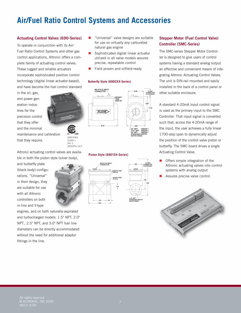
Actuating Control Valves (690-Series)
To operate in conjunction with its Air/
Fuel Ratio Control Systems and other gas
control applications, Altronic offers a com-
plete family of actuating control valves.
These rugged and reliable actuators
incorporate sophisticated position control
technology (digital linear actuator-based),
and have become the fuel control standard
in the oil, gas,
and power gen-
eration indus-
tries for the
precision control
that they offer
and the minimal
maintenance and calibration
that they require.
Altronic actuating control valves are availa-
ble in both the piston style (silver body),
and butterfly plate
(black body) configu-
rations. “Universal”
in their design, they
are suitable for use
with all Altronic
controllers on both
in-line and V-type
engines, and on both naturally-aspirated
and turbocharged models. 1.5" NPT, 2.0"
NPT., 2.5" NPT, and 3.0" NPT fuel line
diameters can be directly accommodated
without the need for additional adaptor
fittings in the line.
� “Universal” valve designs are suitable for use on virtually any carbureted natural gas engine
� Sophisticated digital linear actuator utilized in all valve models assures precise, repeatable control
� Field proven and oilfield-ready
CERTIFIEDCLASS 1DIV. 2 GROUPS C & D
Piston Style (690154-Series)
Butterfly Style (6902XX-Series)
Stepper Motor (Fuel Control Valve) Controller (SMC-Series)
The SMC-series Stepper Motor Control-
ler is designed to give users of control
systems having a standard analog output
an effective and convenient means of inte-
grating Altronic Actuating Control Valves.
The unit is DIN-rail mounted and easily
installed in the back of a control panel or
other suitable enclosure.
A standard 4-20mA input control signal
is used as the primary input to the SMC
Controller. That input signal is converted
such that, across the 4-20mA range of
the input, the user achieves a fully linear
1700-step span to dynamically adjust
the position of the control valve piston or
butterfly. The SMC board drives a single
Actuating Control Valve.
� Offers simple integration of the Altronic actuating valves into control systems with analog output
� Assures precise valve control

All rights reserved© ALTRONIC, INC 2009AEC-C 9-09
8
Available power options include 12 or
24VDC, as well as 110VAC input. Serial
communications capabilities are standard
in all EPC-200 system models. EPC-200
Engine Performance Controllers are often
integrated with other Altronic instruments
in an Altronic Controls-manufactured
panel, providing complete engine/com-
pressor protection and control.
� “Universal” controller suitable for use on turbocharged, fuel-admitted gas engines
� Improves engine performance and efficiency
� Fail-safe design features and fault annunciation
� Seven discrete outputs for sequence control
Air/Fuel Ratio Control Systems and Accessories
EPC-200C Fuel-Admitted Engine Performance ControllerComplete air/fuel ratio and ignition tim-
ing control for fuel-admitted gas engines
is provided by the Altronic EPC-200
Engine Perfor-
mance Control-
ler. Replacing
obsolete OEM
and/or pneu-
matic controls,
this flexible and
fully-configurable
system is an ef-
fective upgrade solution for op-
erators of turbocharged integral
compressor engines, as well as
high-speed, fuel-admitted sepa-
rable engines including many
Superior and MEP models.
Monitored engine RPM plus up to four
other analog inputs are used as control
variables. In a typical application, fuel
manifold pressure, air manifold pressure,
and air manifold temperature are config-
ured as the primary control inputs. The
fourth (unspecified) input is often con-
nected to a variety of devices including
exhaust oxygen sensors, KW sensors, and
calorimeters. Using operating data taken
from the existing controls and determined
during the commissioning process, these
monitored values are used as inputs to
optimize both the engine air/fuel ratio
and the desired ignition timing across the
range of ambient conditions, speeds, and
engine loads. Control of these functions
is accomplished by two independent
4-20mA signals: one for use with an Al-
tronic CPU-series digital ignition system
(timing control), the other to an I/P-
based turbocharger by-pass for wastegate
control (air/fuel). Six user-programmable
solid-state relay outputs are also avail-
able to incorporate common sequencing
functions such as purge, overcrank, crank
disconnect, etc.
CERTIFIEDCLASS 1DIV. 2 GROUP D(DIV. 1 BYPURGING)

All rights reserved© ALTRONIC, INC 2009AEC-C 9-09
9
Speed Governing and Fuel Control Systems
AGV5 Smart Gas Control Valve Designed for service as an actuation
device for a supervisory speed govern-
ing or air/fuel
ratio control
system, the
Altronic AGV5 is
a single-stage,
electronically-
actuated, bal-
anced poppet,
fuel control
valve. Due to
its precision control, rugged
design, and tolerance to fuel
contaminants and corrosives,
the AGV5 is used extensively
on integral compressor applications and
on other large fuel-admitted natural gas
engines (such as Superior and MEP) as
an upgrade over existing pneumatic fuel
actuators.
CERTIFIEDCLASS 1DIV. 2 GROUPS C & D
Control is derived from industry-standard
4-20mA output signals generated by the
associated controller. For speed control
applications, this would require that
all governing logic, RPM and pressure
setpoints, and timers be defined and resi-
dent within the controller itself, driving
the AGV for fuel actuation.
(Note: If a full-authority, turnkey speed
control capability is required, please see
the description of the GOV10/50 Gas
Engine Governing Systems on page 10).
Two models of the AGV5 are available
(standard and high-flow) to accommodate
the fuel flow control needs of engines up
to 10,000 horsepower.
The presence of both pressure and posi-
tion control 4-20mA inputs (and cor-
responding 4-20mA feedback signals for
each) makes it possible for the super-
visory control system to control the gas
manifold to a desired setpoint for startup,
and then to switch to standard governing
logic when the engine comes up to rated
speed. The result of this unique approach
is that the engine starts more consistently
and reliably, and runs in a more stable
fashion. Pairing the AGV5 with such a
supervisory speed control also eliminates
the need for maintenance-intensive and
costly mechanical or bladder-style fuel
valves and actuators, hydraulic governors,
and all linkages associated with them.
� Eliminates mechanical fuel valve, actuator, and linkages
� Allows for improved starting and speed stability
� Regulates gas flow in response to an input signal or signals
� Feeds back valve position and fuel manifold pressure
� Fail safe design: spring-loaded closed in the event of power failure

All rights reserved© ALTRONIC, INC 2009AEC-C 9-09
10
Speed Governing and Fuel Control Systems
GOV10/50 Gas Engine GovernorsTaking an innovative, unique approach to
fuel-admitted gas engine speed control,
the Altronic GOV10/50 Systems bring
both the fuel control valve
and a sophisticated elec-
tronic governor together into
a single, integrated unit.
Designed for use on both
integral compressors such as Cooper-
Bessemer, Clark, Ingersoll-Rand, and
Worthington, as well as high-speed
separables such as Superior and MEP,
these robust, precision-control devices ef-
fectively eliminate troublesome hydraulic
governors, actuators, and linkages. The
result is significantly improved starting
performance and speed stability across
the engine load range.
The GOV systems are mounted directly in
the engine fuel line, and very precisely
control gas flow to the engine by changing
the position of an internal poppet valve.
Using fuel gas pressure as the “muscle”
for the actuation force, this poppet valve
is moved in the open or closed direction
to meter the delivery of the fuel and to
regulate and govern the speed of the en-
gine under all loads. On-board pressure,
differential pressure, and temperature
monitoring sensors, along with engine
RPM and an optional fuel flow mea-
surement capability allow for accurate
control of engine speed. A sophisticated,
user-tunable speed governing algorithim
is resident within the GOV enabling the
system to properly meet the individual
startup, loading, and run requirements
of each engine. Since many engines are
highly sensitive to flooding at startup, the
GOV10 can easily be configured to control
to a specified pressure curve during the
start and warm-up cycles, and then to
switch to an RPM setpoint-based control
strategy for run conditions.
Two GOV models are available—the
GOV10 is used on engines up to approxi-
mately 3,500 hp, and the GOV50 applies
to engines ranging from 3,500 to 10,000
hp. Configuration of the GOV can be ac-
complished through the system Display
Module or via the ModBus-RTU-based
GOV10 Terminal Software included with
each unit. That same RS-485 serial link
can also be used for direct interaction be-
tween the GOV and a supervisory device
for remote system monitoring and control.
� Integrates governing electronics and a state-of-the-art fuel control valve
� Eliminates separate actuators and linkages
� Improves engine starting and speed stability
� Fail-safe design inhibits the flow of fuel to the engine on the loss of power
� Display Module and Terminal Soft-ware assure convenient access to the current run data and configuration values of the GOV system
CERTIFIEDCLASS 1DIV. 2 GROUPS C & D

All rights reserved© ALTRONIC, INC 2009AEC-C 9-09
11
Engine Starting Systems
spots” — and to drastically reduce the
amount of starting air required. More reli-
able remote starting, improved operator
safety (no mechanical barring), reduced
air consumption, and more efficient com-
pressor station operation are just a few of
the benefits of SaveAir™ operation.
All SaveAir™ system electronics are “uni-
versal” in their design and common to all
applications. Engine-specific Logic/Dis-
tribution Module flanges and/or adaptors
ensure a simple installation on virtually
any suitable engine. Configuration and
monitoring of the SaveAir™ system can
be accomplished through the Display
Module or via the PC-based Terminal
Program supplied with every unit.
� Reduces starting air consumption by as much as 70% per start
� Provides more reliable remote starts and eliminates starting “dead spots”
� Replaces failure-prone mechanical air start components with solid-state electronics
� Less costly and complex than ring gear-based starting conversion systems
� “Universal” system hardware set
SaveAir™ Electronic Air Start System
Built to replace troublesome, mainte-
nance-intensive OEM or pneumatic air
start distribution systems, the Exline-
Altronic SaveAir™ Electronic Air Start
System brings solid-state electronic
control to the starting function of air-in-
head starter equipped, integral compres-
sor engines. Eliminating the mechanical
air-start related components, the state-of-
the-art SaveAir™ system introduces sig-
nificant operational advantages, including
a substantial reduction in the required
starting air (up to 70%) and the elimina-
tion of starting “dead spots”.
The heart of the SaveAir™ system is
an innovative, engine-mounted position
sensing device used to determine the pre-
cise angular location of the crankshaft,
even while the engine is at rest. With
accurate radial position data in hand, the
SaveAir™ system electronically actu-
ates air-starting solenoid valves, which
precisely control both the turn-on time
of the air-in-head valves as well as the
duration of the individual air admission
events during
startup. These
unique capa-
bilities enable
the SaveAir™
system to deliver starting air to those cyl-
inders which are most appropriate given
the angular position of the crankshaft —
virtually eliminating engine starting “dead
STARTINGAIR MANIFOLD
IN HEADAIR START VALVE
AIRSUPPLY
SAVEAir LEFT BANK CONTROL
SAVEAirCONTROLSOLENOID
SAVEAir RIGHT BANK CONTROL
ENGINE
4-20mA IN(PRESSURE START SIGNAL)
DIGITAL IN(DISCRETE START SIGNAL)
24 VOLTPOWER
PURGE CONFIRMDIGITAL OUTPUT
MODBUS RTU
TERMINAL PROGRAM
(OPTIONAL)
OR
SAVEAirDISPLAY MODULE
SAVEAirOUTPUTMODULE
SAVEAirLOGIC MODULE
PC-based Terminal Program

The HOERBIGER Group
HOERBIGER Compression Technology is a business unit of HOERBIGER Holding AG, Zug / Switzerland. HOERBIGER is active throughout the world as a leading player in the fields of compression technology, automation technology and drive technology. Its 6,400 employees achieve sales of around 1 billion Euro. The focal points of its business activities include key components and services for compressors, gas engines and turbomachines, hydraulic systems and piezo technology for vehicles and machine tools, as well as components and systems for shift and clutch operations in vehicle drive trains of all kinds. Through innovations in attractive technological niche markets, the HOERBIGER Group sets standards and delivers cutting-edge solutions for the benefit of its customers.
ALTRONIC INC712 Trumbull AvenueGirard, Ohio 44420 USAP: 330-545-4045F: 330-545-9005
Altronic Inc – A Member ofthe HOERBIGER Group
ALTRONIC CONTROLS INC1410 North First StreetGarland, Texas 75040P: 972-494-0522F: 972-272-4017
ALTRONIC EUROPE BVDe Tienden 50A5674 TB NuenenThe NetherlandsP: 011-31-40-2906270F: 011-31-40-2838990
Form AEC-C 9-09