
Catalog 1108-8 Enfinity™ Horizontal Ceiling Water Source ...
Enfinity™ Console Water Source Heat Pumps 1/2 to 1½ TonR-410A Models MHC Standard Range & MHW Geothermal Range
Size 007–018
Catalog 1104
®
� McQuay Enfinity Console Source Heat Pumps Catalog 1104
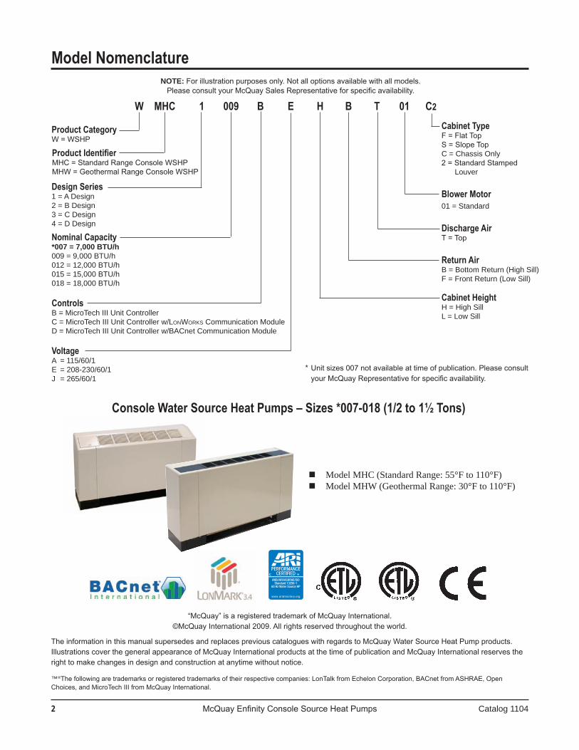
Product CategoryW = WSHP
Product IdentifierMHC = Standard Range Console WSHPMHW = Geothermal Range Console WSHP
Design Series1 = A Design2 = B Design3 = C Design4 = D Design
Nominal Capacity*007=7,000BTU/h009 = 9,000 BTU/h012 = 12,000 BTU/h015 = 15,000 BTU/h018 = 18,000 BTU/h
ControlsB = MicroTech III Unit ControllerC = MicroTech III Unit Controller w/LonWorks Communication ModuleD = MicroTech III Unit Controller w/BACnet Communication Module
VoltageA = 115/60/1E = 208-230/60/1J = 265/60/1
Cabinet TypeF = Flat TopS = Slope TopC = Chassis Only2 = Standard Stamped
Louver
Blower Motor01 = Standard
Discharge AirT = Top
Return AirB = Bottom Return (High Sill)F = Front Return (Low Sill)
Cabinet HeightH = High SillL = Low Sill
W MHC 1 009 B E H B T 01 C2
* Unit sizes 007 not available at time of publication. Please consult your McQuay Representative for specific availability.
NOTE: For illustration purposes only. Not all options available with all models.Please consult your McQuay Sales Representative for specific availability.
Model Nomenclature
“McQuay” is a registered trademark of McQuay International. ©McQuay International 2009. All rights reserved throughout the world.
The information in this manual supersedes and replaces previous catalogues with regards to McQuay Water Source Heat Pump products. Illustrations cover the general appearance of McQuay International products at the time of publication and McQuay International reserves the right to make changes in design and construction at anytime without notice.
™®The following are trademarks or registered trademarks of their respective companies: LonTalk from Echelon Corporation, BACnet from ASHRAE, Open Choices, and MicroTech III from McQuay International.
Console Water Source Heat Pumps – Sizes *007-018 (1/2 to 1½ Tons)
ModelMHC(StandardRange:55°Fto110°F) ModelMHW(GeothermalRange:30°Fto110°F)
Catalog 1104 McQuay Enfinity Console Water Source Heat Pumps �
Factory-installed,unit-mountedthermostatssavetimeandmoneyversusinstallingwall-mountedthermostats.
Widerangeoffactory-installedoptions,includingelec-tricheat,motorizedvalvesandthermostatoptionshelpyou meet more specific application requirements with minimumdesignorinstallationtimeandexpense.
Easy, Low-Cost Maintenance Easyaccesstotheunitcompressor(endpanel),fan
sectionandcoil(frontpanel)andunitcontrols(leftorrightendpanel).
Aeasilyremovableblowermotorallowsthetangen-tialfanwheeltoremaininthehousingduringmotorreplacement.
Ahingedcontrolboxallowseasyaccesstothepipingcompartment.
Quiet Operation New Gentleflo™ fan wheel allows the fan motor to
operate at lower speed for quieter operation.
High efficiency rotary compressor mounted on a mass platesystemreducesnoiseduetovibration.
Superior Indoor Air Quality (IAQ) Removable,non-corrosiveanddouble-slopedpolymer
drainpanpromotespositivecondensatedrainage.
Optionalclosed-cellinsulationpreventsinsulationfibers from entering the air stream.
R-410A Refrigerant With Zero Ozone Depletion Potential or Phase-Out Date R-410A is classified as A1/A1 – lower toxicity, no
flame propagation – per ASHRAE Standard 31.
IntroductionEnfinity™ Water Source Heat Pumps
More than 30 years ago, McQuay designed the first complete line of water source heat pumps for high efficien-cy, individually-zoned comfort control in offices, schools, assistedlivingfacilities,manufacturingfacilitiesandothercommercialbuildings.Ourreputationforoutstandingreli-ability and quiet operation has been reinforced in thousands ofsuccessfulinstallations.
Enfinity water source heat pumps incorporate the best of ourpastandthebestofwhat’snew.Usingfeedbackfrombuildingowners,consultingengineers,contractorsandser-vice engineers, we designed Enfinity products to give you maximum flexibility to design, install, operate and maintain theidealwatersourceheatpumpsystemforyourbuildingproject.Andweincorporatednon-ozonedepletingR-410Arefrigerant, which–along with high Energy Efficiency Ra-tios (EER’s)–helps preserve our environment and precious energyresources.
With Enfinity Water Source Heat Pumps, you benefit from:High efficiency that minimizes environmental impact and lowers operating costs UnitsexceedASHRAEStandard90.1minimum
requirements
Standard range or geothermal application flexibility
Engineered For Flexibility and Performance Twocabinetsizes,eachwithMcQuay’ssubtle
aestheticandsmallfootprintdesign,makeiteasytomeet the space requirements of your new construction orreplacementapplication.
MicroTech® unit controller with Open Choices™ fea-tureallowseasy,lowcostintegrationwiththeBuildingAutomationSystem(BAS)ofyourchoice.
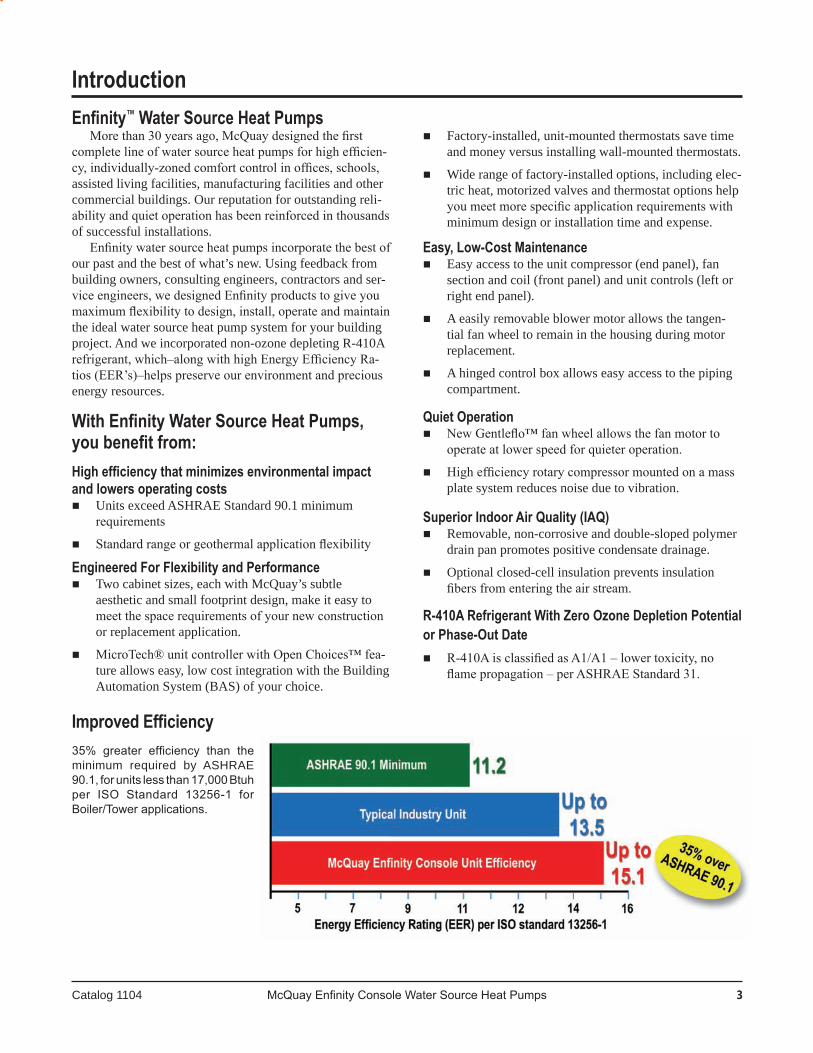
Improved Efficiency35% greater efficiency than the minimum required by ASHRAE 90.1, for units less than 17,000 Btuh per ISO Standard 13256-1 for Boiler/Tower applications.
4 McQuay Enfinity Console Source Heat Pumps Catalog 1104
Console Unit Features & Options
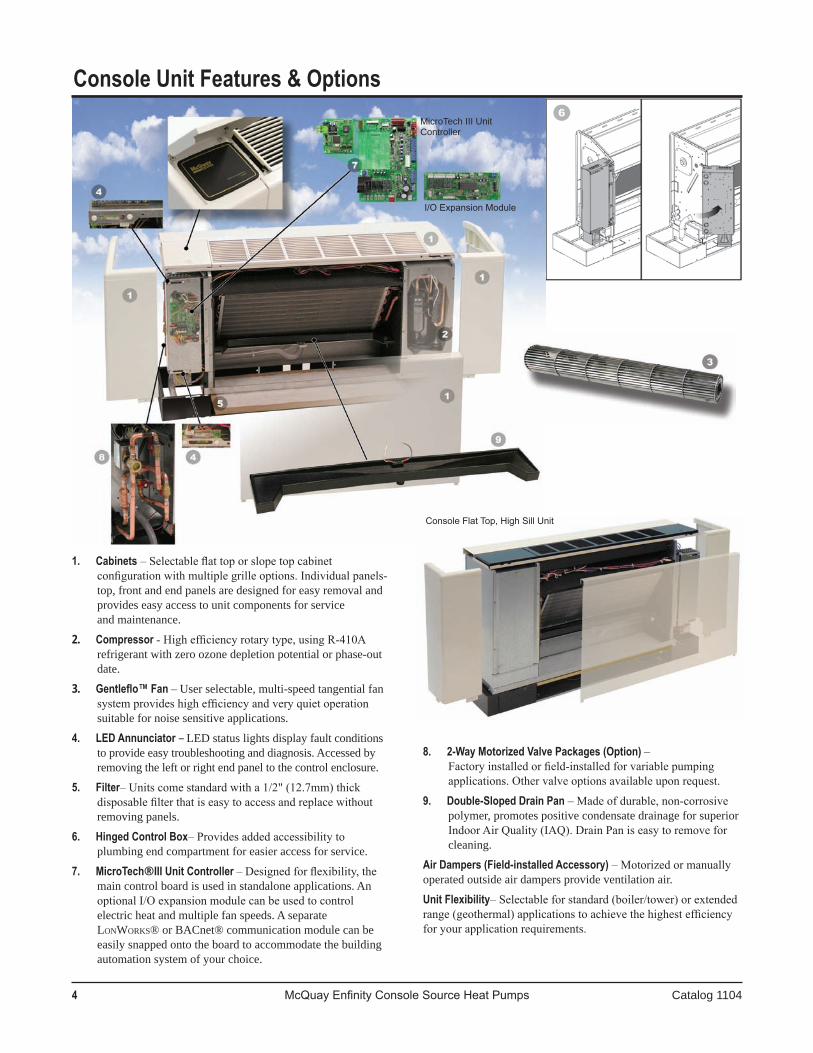
1. Cabinets – Selectable flat top or slope top cabinet configuration with multiple grille options. Individual panels- top,frontandendpanelsaredesignedforeasyremovalandprovideseasyaccesstounitcomponentsforserviceandmaintenance.
�. Compressor - High efficiency rotary type, using R-410A refrigerantwithzeroozonedepletionpotentialorphase-outdate.
�. Gentleflo™ Fan – Userselectable,multi-speedtangentialfansystem provides high efficiency and very quiet operation suitablefornoisesensitiveapplications.
4. LED Annunciator – LEDstatuslightsdisplayfaultconditionstoprovideeasytroubleshootinganddiagnosis.Accessedbyremovingtheleftorrightendpaneltothecontrolenclosure.
5. Filter– Units come standard with a 1/2" (12.7mm) thick disposable filter that is easy to access and replace without removingpanels.
6. Hinged Control Box– Provides added accessibility to plumbingendcompartmentforeasieraccessforservice.
7. MicroTech® III Unit Controller – Designed for flexibility, the maincontrolboardisusedinstandaloneapplications.Anoptional I/O expansion module can be used to control electricheatandmultiplefanspeeds.AseparateLonWorks®orBACnet®communicationmodulecanbeeasilysnappedontotheboardtoaccommodatethebuildingautomationsystemofyourchoice.
8. 2-Way Motorized Valve Packages (Option) – Factory installed or field-installed for variable pumping applications. Other valve options available upon request.
9. Double-Sloped Drain Pan – Made of durable, non-corrosive polymer,promotespositivecondensatedrainageforsuperiorIndoor Air Quality (IAQ). Drain Pan is easy to remove for cleaning.
Air Dampers (Field-installed Accessory) – Motorized or manually operatedoutsideairdampersprovideventilationair.
Unit Flexibility– Selectable for standard (boiler/tower) or extended range (geothermal) applications to achieve the highest efficiency for your application requirements.
MicroTech III Unit Controller
Console Flat Top, High Sill Unit
I/O Expansion Module

Catalog 1104 McQuay Enfinity Console Water Source Heat Pumps �
Accesstothecompressoristhrougharemovableendpanel.Thecompressorisisolatedfromtheunitwithexternalvibrationmounts, mass plate/viscoelastic dampening material and the compartment is totally insulated to make the quietest console unitonthemarket.Safetycontrolsincludelowtemperature(freezestat) and refrigerant high pressure switches.Thecontrolboxishingedforeasyaccesstoallofthecontrols.The MicroTech III unit controller offers both standalone or communicating(LonWorks or BACnet)controloptions.
Eachusesaprintedcircuitboardforcleanwiringandalowvoltage control circuitwith a 50VA transformer. See“Controls”sectionformoredetailedinformation.Mainpoweris made to a chassis-mounted 2" x 4" (51mm x 102mm) junctionbox.
The fan section employs McQuay's Gentleflo tangential system fan and efficient, two-speed PSC motor for selectable airflow and/or noise level. Access to the fan wheel is made through the toppanel.Themotor issecured to thechassiswiththreescrewsforeasyservice.
Water piping connections are 1⁄2" FPT fittings which terminateintheoutwardpositioninthepipingcompartmentfor easy access. Unique left- and right-hand piping (includes condensate and electrical) locations are available. The 3⁄4" (19mm) I.D. flexible clear vinyl condensate drain tube is internally trapped and extends 14" (356mm) into the piping compartment for easy connection. Piping (electrical and condensatealso)canenterthroughthebackwallorthroughthe floor within the subbase. The chassis allows for a piping compartmentbetweenthechassisandthecabinet.
Optional Factory Installed FeaturesBoilerless system electric heat eliminates the need for
aboiler in theheatpumpwater loop.Anelectricheater isadded to the discharge side of the fan scroll. If the entering watertemperaturefallsto58°F(15°C)thethermostatlocksout compressor operation.On a call for heat, the electricheater is energized.When the enteringwater temperatureraises,theunitwillresumecompressoroperationonacallforheat.Anemergencyheatswitchallowselectricheatingif the compressor should ever fail. Each unit has variousheatersizestoselectfrom.Notavailableon115voltunits.NotCSAlisted.
Console Design Features
ConfigurationConsole water source heat pumps are available in five
cooling capacity sizes, from 1⁄2 through 1½ tons, (1757 to 5274 watts). Each is available in four different configurations.
Flat top units meet the traditional requirements for a rugged unit. Slope topunits offer amoremodern look.Thehighsilhouette unit is 25" (635mm) high and the low silhouette unit is only 22½" (572mm) high. The overall unit dimensions are very compact; unit sizes 007 through 012 are 46" (1168mm) long and sizes 015 through 018 are 54" (1372mm) long. All units are a constant 10¾" (273mm) deep for minimum floor spaceandaconsistent“look”forallunitsizes.
All units incorporate a slide-out chassis conceptwhichallows it to be installed easily or removed and replaced quickly when service is required to minimize downtime for the space theunitserves.Thecabinetismadeupofindividualpanels,eachofwhichcanbeeasilyremovedtoexposethechassisforfield hook-up of water and electrical connections. The chassis easilyslidesoffthesubbaseforserviceorchangeout.
CabinetAll cabinets are painted with optional Antique Ivory
or Cupola White baked enamel finish for an aesthetically pleasingappearancethatmatchesroomdecor.Thedischargegrilles and subbase can be Oxford Brown or match thecabinetry on flat top or slope top units.
The shallow 22° slope top cabinet is constructed of 18-gaugesteel.Thetopandsidecornersandgrilleareconstructedof tough, impact-resistantABSpolycarbonate.The grilleextendstothefrontandsidesforasmoothlookaswellasprovidingacurtainstopinback.Thedischargegrillescanberotatedtodirecttheairinan11°anglefromtheverticalandcanbereversedfora33°dischargeangle.Thecontroldoorhasa finger slot and simply lifts up for access to the thermostat. Overall, the slope top unit allows minimal airflow interference fromcurtainsandobjectsrestingonthecabinet,whileatthesametimeprovidingarugged,aestheticallypleasinglook.
The flat top cabinet is constructed of 18-gauge steelwith grille options thatmeet basic needswith its ruggedconstructionandits11°dischargeangle.
ChassisThechassishousesthefansection,refrigerantcircuitand
controls.Theairenters through thebottomof thechassis,through the subbaseor through the front panel in low sillunits.
The refrigeration system includes a rotary compressor,reversingvalve,coaxialheatexchanger,capillarytubes,aircoil,highand lowsideaccessvalves, andsafetycontrols.

� McQuay Enfinity Console Water Source Heat Pumps Catalog 1104
Control Options – Control Choices And Added Functionality
Control Description Application Protocol
The MicroTech III unit controller is a standalone microprocessor-basedcontrol board conveniently locatedintheunitcontrolboxforaccessibil-ity.Theboard isdesigned toprovidestandalonecontrolofaWaterSourceHeat Pump using a wall thermostat or awallmounted temperature sen-sor. Each unit controller is factoryprogrammed,wired, and tested. Foradded functionality an optional I/O expansionmoduleinterconnectstotheMicroTech III controller for complete controlandoperationofyourMcQuaywatersourceheatpump.
The I/O Expansion Module is an exten-sion of the Microtech III unit controller andprovidesadditional functionality.It is required on all units with an LED annunciatorandprovidesoperationoftheboilerlesselectricheatfeature.
The MicroTech III unit controller can accept a plug-inLonWorks commu-nicationmodule to provide networkcommunicationsandaddedfunctional-itytoeasilyintegratewithanexistingBAS.Thecommunicationmodulecanbe factory- or field-installed and istested with all logic required to monitor andcontroltheunit.
The MicroTech III unit controller canacceptaplug-inBACnetcommu-nicationmodule to provide networkcommunicationsandaddedfunctional-itytoeasilyintegratewithanexistingBAS.Thecommunicationmodulecanbe factory- or field-installed and istested with all logic required to monitor andcontroltheunit.
Thecontrolboxisaccessiblethroughtheleftorrightendcorner panel. It houses the major operating electrical controls including the MicroTech® III unit controller, transformer, compressor relayand fan relay.Eachcomponent is easilyaccessedforserviceorreplacement.
Four unique control choices are offered with the Micro-Tech III unit controller:
■ Standalone operation using a MicroTech III unit controller
■ MicroTech III unit controller with I/O Expansion module
■ MicroTech III unit controller with a Lonworks® commu-nicationmodule
■ MicroTech III unit controller with a BACnet® communica-tionmodule
Each option features direct quick-connect wiring to all unit-controlledcomponentsfor“clean”wiringinsidethecontrolbox.Eachcontrolcircuitboardreceivespowerfroma50VAtransformer.
MicroTech III
Eachunit controller is factory programmed,wired,andtestedforcompletecontrolofsinglezone,stand-aloneoperationofyourMcQuayWaterSourceHeatPump.
Allowsfor:• Monitoringofenteringwatertemperaturefor boilerlesselectricheatcontrol.• Outputsforoptionalelectricheat.
Designed to be linkedwith a centralized buildingautomationsystem(BAS)throughaLonWorkscom-municationsnetworkforcentralizedschedulingandmanagementofmultipleheatpumps.
Designed to be linkedwith a centralized buildingautomation system (BAS) through aBACnet com-municationsnetworkforcentralizedschedulingandmanagementofmultipleheatpumps.
Un i t -moun t edor wall-mountedthermostat
Un i t -moun t edor wall-mountedthermostat
LonMark 3.4
BaCnet
(Standalone) Unit Controller
LonWorks
Communication Module
BACnet
Communication Module
I/O Expansion Module
Catalog 1104 McQuay Enfinity Console Water Source Heat Pumps 7
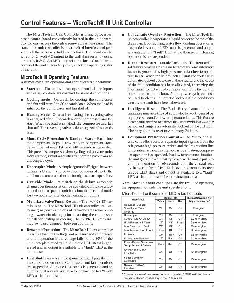
The MicroTech III Unit Controller is a microprocessor-basedcontrolboardconvenientlylocatedintheunitcontrolboxforeasyaccessthrougharemovableaccesspanel.Thestandaloneunitcontrollerisahardwiredinterfaceandpro-vides all the necessary field connections. The board can be wired for 24-volt AC output to the wall thermostat by using terminalsR&C.AnLEDannunciatorislocatedonthefrontcorner of the unit chassis to quickly check the operating status oftheunit.
MicroTech III Operating FeaturesAssumescyclefanoperation-notcontinuousfanoperation:
■ Start-up –Theunitwillnotoperateuntilalltheinputsandsafetycontrolsarecheckedfornormalconditions.
■ Cooling mode –Onacallforcooling,thecompressorandfanwillstart0to30secondslater.Whentheloadissatisfied, the compressor and fan shut off.
■ Heating Mode –Onacallforheating,thereversingvalveis energized after 60 seconds and the compressor and fan start. When the load is satisfied, the compressor and fan shut off. The reversing valve is de-energized 60 seconds later.
■ Short Cycle Protection & Random Start –Eachtimethecompressorstops,anewrandomcompressorstart-delay time between 180 and 240 seconds is generated. Thispreventscompressorshortcyclingandpreventsunitsfromstartingsimultaneouslyaftercomingbackfromanunoccupiedcycle.
■ Unoccupied Mode –Asimple“grounded”signalbetweenterminals U and C (no power source required), puts the unitintotheunoccupiedmodefornightsetbackoperation.
■ Override Mode –A switch on the deluxe automaticchangeoverthermostatcanbeactivatedduringtheunoc-cupiedmodetoputtheunitbackintotheoccupiedmodefortwohoursforafter-hoursheatingorcooling.
■ Motorized Valve/Pump Restart – The IV/PR (H8) ter-minals on the The MicroTech III unit controller are used toenergize(open)amotorizedvalveorstartawaterpumptogetwatercirculatingpriortostartingthecompressoron call for heating or cooling. The IV/PR (H8) terminal may be “daisy chained” between 200 units.
■ Brownout Protection – The MicroTech III unit controller measurestheinputvoltageandwillsuspendcompressorandfanoperationifthevoltagefallsbelow80%oftheunit nameplate rated value. A unique LED status is gen-eratedandanoutputisavailabletoa“fault”LEDatthethermostat.
■ Unit Shutdown –Asimplegroundedsignalputstheunitintotheshutdownmode.Compressorandfanoperationsare suspended. A unique LED status is generated and an outputsignalismadeavailableforconnectiontoa“fault”LEDatthethermostat.
Control Features – MicroTech® III Unit Controller■ Condensate Overflow Protection – The MicroTech III
unit controller incorporates a liquid sensor at the top of the drain pan. Upon sensing water flow, cooling operation is suspended. A unique LED status is generated and output isavailabletoa“fault”LEDatthethermostat.Heatingoperationisnotsuspended.
■ Remote Reset of Automatic Lockouts –TheRemoteRe-setfeatureprovidesthemeanstoremotelyresetautomaticlockouts generated by high-pressure and/or low-tempera-ture faults. When the MicroTech III unit controller is in automaticlockoutduetooneofthesefaults,andthecauseofthefaultconditionhasbeenalleviated,energizingtheO-terminalfor10secondsormorewillforcethecontrolboardtoclearthelockout.Aunitpowercyclecanalsobeusedtoclearanautomaticlockoutif theconditionscausingthefaulthavebeenalleviated.
■ Intelligent Reset – The Fault Retry feature helps tominimizenuisancetripsofautomaticlockoutscausedbyhigh-pressure and/or low-temperature faults. This feature clears faults the first two times they occur within a 24-hour periodandtriggersanautomaticlockoutonthe3rdfault.The retry count is reset to zero every 24 hours.
■ Equipment Protection Control – The MicroTech III unitcontroller receivesseparate inputsignals fromtherefrigeranthigh-pressureswitchandthelowsuctionlinetemperature sensor. In a high-pressure situation, compres-sor operation is suspended. In a low temperature situation, theunitgoesintoadefrostcyclewheretheunitisputintocooling operation for 60 seconds until the coaxial heat exchangerisfreeofice.Eachswitchgeneratesitsownunique LED status and output is available to a “fault” LEDatthethermostatifeithersituationexists.
Note:Mostunitfaultconditionsaretheresultofoperatingthe equipment outside the unit specifications.
Mode / Fault Status LED’s Thermostat Alarm Light Yellow Green Red Output-Terminal “A” Occupied, Bypass, Standby, or Tenant Off On Off Energized Override Unoccupied On On Off Energized Condensate Overflow On Off Off De-energized High Pressure 1 Fault Off Off Flash De-energized Low Pressure 1 Fault Off Off On De-energized Low Temperature 1 Fault Flash Off Off De-energized Brownout Off Flash Off De-energized Emergency Shutdown Off Flash Off De-energized Room/Return Air or Low
Flash Flash On De-energized Temp Sensor 1 Failure
Service Test Mode On On Off De-energized
Enabled 1
Serial EEPROM On On On De-energized Corrupted Network “Offline” Off Off Off De-energized Received
MicroTech III unit controller LED & fault outputs
1 Compressor relay/compressor terminal is labeled COMP, switched line of the same electric input as any of the L1 terminals.

8 McQuay Enfinity Console Source Heat Pumps Catalog 1104
I/O Expansion Module Configuration Jumper Terminals
Adding an I/O Expansion Module (with an interconnect cable)totheunitcontrollerallowstheoperationofboilerlesselectricheatwiththeConsoleWaterSourceHeatPump.
FeaturesStandard Heat Pumps / Single Circuit Units • Monitorsenteringwatertemperaturefor
boilerlesselectricheatcontrol
I/O Expansion Module
The I/O Expansion Module is a factory installed option. It is an extension of the MicroTech III unit controller and providesextrafunctionality.The I/O Expansion Module has 2 main purposes:
• The I/O Expansion Module has outputs to control electric heat on a standard Water Source Heat Pump.
• The I/O Expansion Module has an independent LED annunciatortoidentifyoperationalfaultconditionsfortheelectricheater.
I/O Expansion Module LED & Fault Outputs
Jumper Description Options JP1 Number of Open for single compressor
Compressors Shorted for dual compressor JP2 Hot Gas/ Open to disable reheat Water Reheat Shorted to enable reheat JP3 and JP4 open for no supplemental heat JP3
Supplemental JP3 open, JP4 shorted for
& JP4 Heat Type boilerless electric heat JP3 and JP4 shorted is an invalid setting JP5 and JP6 open for single-speed fan JP5 open, JP6 shorted for JP5 Fan Speed three-speed fan & JP6 Selection JP5 shorted and JP6 open for two-speed fan JP 5 and JP6 shorted is an invalid setting JP7 Compressor Open for single-speed compressor Speed Type Shorted for two-speed compressor JP8 Future Spare
I/O Expansion Module Configuration Jumper Settings
1 Boilerless electric heat only2 Alarm/fault LED indications take precedence over service test mode LED
indication. The controller shall use service test mode if the service test mode jumper is installed, even if the LED’s indicate an alarm/fault.
Note: Mode / Faults are listed in order of priority.
Status LED's
Thermostat Alarm
Mode / Fault Yellow Green Red Light Output
Terminal “A”
Invalid Configuration Flash Flash Off De-energized Jumper Setting
Base Board Off Flash Flash N/A Communication Fail
High Pressure #2 Fault Off Off Flash De-energized
Low Pressure #2 Fault Off Off On De-energized
Low Suction Temp #2 Fault Flash Off Off De-energized Sensor Failures Low Suction
Low Suction Temp #2, Flash Flash On De-energized
1EWT (w/ Boilerless EH only)
2 Service Test Mode Enabled Flash Flash Flash De-energized
Unoccupied Mode On On Off Energized
Occupied, Bypass, Standby, or Tenant Off On Off Energized Override Modes Normal Operation Off On Off De-energized
Jumper Terminals
= Not used with Console Water Source Heat Pump unit.
= Not used with Console Water Source Heat Pump unit.
Control Features – MicroTech III with I/O Expansion Module

Catalog 1104 McQuay Enfinity Console Water Source Heat Pumps 9
MicroTech III Unit Controller with Communication Modules Features
The MicroTech III Unit Controller with LonWorks orBACnetCommunicationModuleorchestratesthefollowingunitoperations:
Enableheatingandcoolingtomaintainspace temperaturesetpointbasedonaroomsensorsetting
Enablefanandcompressoroperation
Monitors all equipment protection controls
Monitorsroomanddischargeairtemperatures
Monitorsleavingwatertemperature
Relaysstatusofallvitalunitfunctions
Anamber,on-boardstatusLEDindicatesthestatusoftheMicroTech III LonWorksorBACnetmodule.
The MicroTech III unit controller includes:
Aunit-mountedreturnairsensor
Aunit-mounteddischargeairsensor
Aleavingwatertemperaturesensor
Thecommunicationmodulesprovidenetworkaccesstosetpointsforoperationalcontrol
Availablewallsensorsinclude:
Roomsensor
RoomsensorwithLEDstatusandtenantoverride button
TemperaturesensorwithLEDstatus,timed-override button,and±3°Fsetpointadjustment
RoomsensorwithLEDstatus,timed-override button,55°to90°Fsetpointadjustment
MicroTech III Unit Controller with LonWorks or BACnet Communication Module
Each McQuay Console Water Source Heat Pump can be equipped with a LonWorks or BACnet communication module.TheLonWorks module is LonMark 3.4 certified anddesignedtocommunicateoveraLonWorkscommuni-cationsnetworktoaBuildingAutomationSystem(BAS).TheBACnetmoduleisdesignedtocommunicateoveraBACnet MS/TP communications network to a building automationsystem.Bothcontrollersaremicroprocessor-based and can be factory or field-installed.
Thecontrolmodulesareprogrammedandtestedwithall the logic required to monitor and control the unit. Op-tionalwallsensorsmaybeusedwiththecommunicationmodulestoprovidelimitedlocalcontroloftheConsoleWater Source Heat Pump. The MicroTech III unit controller monitorswaterandairtemperaturesandpassesinformationtothecommunicationmodule.ThemodulecommunicateswiththeBAS,toprovidenetworkcontroloftheWaterSource Heat Pump.
MicroTech III LonWorks Communication ModuleTheLonWorkscommunicationmoduleisdesignedfor
unitsthatareintegratedintoaLonWorkscommunicationnetworkforcentralizedschedulingandmanagementofmultipleheatpumps.
MicroTech III BACnet Communication ModuleDesignedtobelinkedwithacentralizedbuildingauto-
mationsystem(BAS)throughaBACnetcommunicationsnetworkforcentralizedschedulingandmanagementofmultipleheatpumps.
Control Features – MicroTech III with Communication Module

10 McQuay Enfinity Console Source Heat Pumps Catalog 1104
Applications – Systems
Watersourceheatpumpsystemsareoneofthemostef-ficient, environmentally friendly systems available for heating and cooling buildings. High-efficiency, self contained units (sizes 7,000 btuh to 420,000 btuh) can be placed in virtually anylocationwithinabuilding.Eachunitrespondsonlytotheheatingorcoolingloadoftheindividualzoneitserves.Thispermitsanexcellentcomfortlevelforoccupants,bettercontrolofenergyuseforbuildingownersandlowerseasonaloperating costs. The Air-Conditioning Refrigeration Institute (ARI) and the International Standards Organization (ISO) publishstandardssothatwatersourceheatpumpsareratedfor specific applications. The ARI/ISO loop options shown in thiscatalogaretypicalwatersourceheatpumploopchoicesavailable in today’s market. These systems offer benefits rang-ing from low cost installation to the highest energy efficiency availableinthemarkettoday.
Open Loop Well Water Applications: ARI 325 / ISO 13256-1
“OpenLoop”wellwatersystemsusegroundwatertoremoveoraddheattotheinteriorwaterloop.Thekey benefit of an open loop system is the constant water temperature, usually 50ºF to 60ºF, which provides efficient operation at a low first cost. Most commercial designers incorporateaheatexchangertoisolatethebuildingloopfromthewellwater.Usingheatexchangerscanreducemaintenanceissueswhilestillallowingthetransferofheatfrom unit to unit as with the “Boiler/Tower System”. A suc-cessfuldesignprovidesanampleamountofgroundwater(approximately 2 GPM per ton) and adequate provisions for discharging water back to the aquifer or surface. Open Loopapplicationsarecommonlyusedincoastalareaswheresoilcharacteristicsallowreinjectionwellstoreturnthe water back to the aquifer. Note that some states have re-quirements on the depths of return water reinjection wells, andsuchwellsmustbeapprovedbytheUnitedStatesEn-vironmental Protection Agency. Also, bad water quality can increaseproblemswithheatexchangerscaling.Suspendedsolidscanerodetheheatexchanger.Strainerscanbeusedtocontainsuspendedsolids.
Open Loop Well Application
Boiler / Tower Applications: ARI 320 / ISO 13256-1
A “Boiler/Tower” application uses a simple two-pipe watercirculatingsystemthataddsheat,removesheatortransfersrejectedheattootherunitsthroughoutthebuild-ing.Thewatertemperatureforheatingisgenerallymain-tained between 65ºF – 70ºF and is usually provided by a naturalgasorelectricboilerlocatedinamechanicalroom.Thecondensingwatertemperature,duringcoolingmonths,is maintained between 85ºF and 95ºF and requires the use ofacoolingtowertodissipatewasteheat.Coolingtow-erscanbelocatedontheroof,orinsideoradjacenttothebuilding.Thisapplicationcanbethelowestcostoftheloopoptionsavailable.Note: ASHRAE 90.1 standards require that circulating pumps over 10 HP will require use of “variable frequency drive” equipment and pipe insulation to be used whenever water temperatures are below 60 degrees and above 105 degrees.SeeASHRAE90.1Standardsfordetails.
Boiler/Tower Application

Catalog 1104 McQuay Enfinity Console Water Source Heat Pumps 11
Applications – Systems
Closed Loop Geothermal Applications ARI 330/ISO 13256-1
“VerticalClosedLoop”applicationsareinstalledbydrillingverticalboreholesintotheearthandinsertinga plastic polyethylene supply/return pipe into the holes. Theverticalwellsareconnectedinparallelreversereturnfashiontoallowthewaterfromthebuildingtocirculateevenly throughout the borefield. The circulating fluid dis-sipatesheattothegroundinasimilarmannerasa“tower”and adds heat back to the loop like a boiler. If properly designed, the loop field can maintain the loop temperatures necessarytoconditionthebuildingwithouttheuseofaboileroratower.Looptemperaturesusuallyrangefrom37ºF to 95ºF in Northern climates. Southern applications canseetemperaturesrangingfrom40ºFto100ºF.Thenumberofboreholesandtheirdepthshouldbedeterminedby using commercial software that is specifically designed forverticalgeothermalapplications.Typicalboredepthsofaverticallooprangefrom150to400feetandgenerallyrequire about 250 feet of surface area per ton of cooling.
Vertical Loop Application
Aclosedloop“Horizontal”geothermalapplicationissimilartoaverticalloopapplicationwiththeexceptionthattheloopsareinstalledintrenchesapproximately5feetbelowthegroundsurface.Thepipingmaybeinstalledusing a “four-pipe” or “six-pipe” design and could require 1,500 to 2,000 square feet of surface area per ton of cooling.Looptemperaturesforacommercialapplicationcanrangefrom35ºFto95ºFinNorthernclimates.Southernclimatescanseetemperaturesrangingfrom40ºFto100ºF.Horizontalloopsaregenerallynotappliedinurbanareasbecauselanduseandcostscanbeprohibitive.Newadvancesininstallationprocedureshaveimprovedtheassembly time of horizontal loops while keeping the first costlowerthanaverticalloop.
Horizontal Loop Application
A“SurfaceWater”or“Lake”closedloopsystemisa
geothermalloopthatisdirectlyinstalledinalakeorbodyof water that is near the building. In many cases, the body ofwaterisconstructedonthebuildingsitetomeetdrain-age or aesthetic requirements. Surface loops use bundled polyethylenecoilsthatareconnectedinthesamemannerasaverticalorhorizontalloopusingaparallelreversereturndesign.Thesizeandthedepthofthelakeiscritical.Commercialdesignservicesshouldbeusedtocertifythatagiven body of water is sufficient to withstand the building loads.Looptemperaturesusuallyrangefrom35ºFto90ºFandprovetobethebestcoolingperformerandlowestcostloopoptionofthethreegeothermalloops.Someapplica-tionsmaynotbegoodcandidatesduetopublicaccessordebris problems from flooding.
Surface Water Loop Application

1� McQuay Enfinity Console Source Heat Pumps Catalog 1104
Condensate DrainThefactoryprovidedcondensatedraintraponthe
consoleunitislocatedinsidetheendcabinet.Condensateremovalpipingmustbepitchedawayfromtheunitnotless than 1/4" per foot. A vent is required after the trap so thatthecondensatewilldrainawayfromtheunit.Theventcanalsoactasacleanoutifthetrapbecomesclogged.Toavoidhavingwastegasesenteringthebuilding,thecondensate drain should not be directly piped to a drain/waste/vent stack. See local codes for the correct application ofcondensatepipingtodrains.
McQuay has available optional fire-rated flexible hoses tobetterfacilitatesupplyandreturnpipingconnections.These flexible hoses reduce vibration between the unit and therigidpipingsystem.
Fire Rated Supply or Return Hoses
Applications Considerations
Unit LocationThe Console Water Source Heat Pump is typically
installedonanexteriorwall.LocateaConsoleunittoallowforeasyremovalof
the filter and access panels. Allow a minimum of 18" (46 cm)clearanceoneachsideoftheunitforserviceandmaintenanceaccess.
To reduce noise emissions, install a field-provided 1/4 inchthick,rubberisolatorpadbelowtheentirebaseoftheunit. The pad should be equal to the overall foot-print size oftheunittoprovidesounddampeningoftheunitwhilein operation. The unit must sit flat on the floor to prevent unwantednoiseandvibration.
PipingTheconsolewatersourceheatpumpunitistypically
connected to the supply / return piping using a “reverse return” piping system which includes a flow control device so that flow requirements are met for each zone. A short, high pressure “flexible hose” is used to connect theunittothebuilding’shardpipingandactsasasoundattenuatorforboththeunitoperatingnoiseandhydronicpumping noise. One end of the hose has a swivel fitting to facilitateremovaloftheunitforreplacementorservice.Include supply and return shutoff valves in the design to allowremovalofaunitwithouttheneedtoshutdowntheentireheatpumpsystem.Thereturnvalvemaybeusedforbalancingandwilltypicallyhavea“memorystop”sothat it can be reopened to the proper position for the flow required. Fixed flow devices are commercially available andcanbeinstalledtoeliminatetheneedformemorystopshut off valves. Include Pressure / Temperature ports to allow the service technician to measure water flow and unit operation.
Typical Console Installation
Hose Type Nominal Max. Recommended Minimum Minimum
Length Working Pressure
Burst Pressure Bend @ 70° to 90° Radius
1/2" MPT 9" 400 psig 1200 psig 2½"
Supply
12" 400 psig 1200 psig 2½"
& Return
18" 400 psig 1200 psig 2½"
24" 400 psig 1200 psig 2½"
Assembled Length
Fixed End, MPT Female Swivel Adapter
Catalog 1104 McQuay Enfinity Console Water Source Heat Pumps 1�
Applications – Systems
Thermal Expansion Valve
Water to Refrigerant Heat Exchanger
Water In
Water Out
Compressor
Reversing Valve
Air to Refrigerant
Heat Exchanger
Coil
Blower
Conditioned Air(Cooling)
Return Air
Sensing Bulb andCapillary Tube
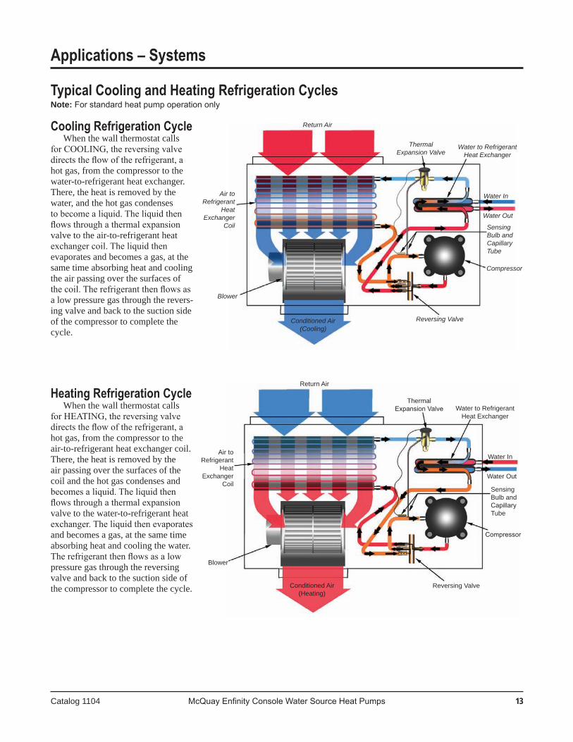
Cooling Refrigeration CycleWhenthewallthermostatcalls
for COOLING, the reversing valve directs the flow of the refrigerant, a hotgas,fromthecompressortothewater-to-refrigerantheatexchanger.There,theheatisremovedbythewater,andthehotgascondensesto become a liquid. The liquid then flows through a thermal expansion valvetotheair-to-refrigerantheatexchanger coil. The liquid then evaporatesandbecomesagas,atthesametimeabsorbingheatandcoolingtheairpassingoverthesurfacesofthe coil. The refrigerant then flows as alowpressuregasthroughtherevers-ingvalveandbacktothesuctionsideofthecompressortocompletethecycle.
Thermal Expansion Valve
Water In
Water Out
Compressor
Reversing Valve
Blower
Return Air
Sensing Bulb andCapillaryTube
Heating Refrigeration CycleWhenthewallthermostatcalls
for HEATING, the reversing valve directs the flow of the refrigerant, a hotgas,fromthecompressortotheair-to-refrigerantheatexchangercoil.There,theheatisremovedbytheairpassingoverthesurfacesofthecoilandthehotgascondensesandbecomes a liquid. The liquid then flows through a thermal expansion valvetothewater-to-refrigerantheatexchanger. The liquid then evaporates andbecomesagas,atthesametimeabsorbingheatandcoolingthewater.The refrigerant then flows as a low pressuregasthroughthereversingvalveandbacktothesuctionsideofthecompressortocompletethecycle.
Typical Cooling and Heating Refrigeration CyclesNote:For standard heat pump operation only
Conditioned Air(Heating)
Water to Refrigerant Heat Exchanger
Air to Refrigerant
Heat Exchanger
Coil

14 McQuay Enfinity Console Water Source Heat Pumps Catalog 1104
Applications – Unit Selection
Achievingoptimalperformancewithwatersourceheatpump systems requires both accurate system design and proper equipment selection. Use a building load program to determinetheheatingandcoolingloadsofeachzonepriorto making equipment selections. With this information, the McQuay SelectTools™ software selection program for Water Source Heat Pumps can be used to provide fast, ac-curateandcompleteselectionsofallMcQuaywatersourceheatpumpproducts.SelectToolssoftwareisavailablebycontactingyourlocalMcQuayRepresentative.
WhilewerecommendthatyouuseMcQuaySelectToolssoftwareforallunitselections,manualselectionscanbeaccomplishedusingthesamezoneloadinformationandthecapacitytablesavailableinthiscatalog.
Boiler / Tower Application Manual Selections:
Thefollowingexampleillustratesatypicalselectionfora zone in a boiler/tower system for a commercial building.
Abuildingloadprogramdeterminesthatthiszoneneeds10,430 BTUH of total cooling, 6,950 BTUH of sensible coolingand9,150BTUHoftotalheating.Thewatertem-peratures for the boiler/tower system are 90ºF for cooling and 70ºF for heating. The return air temperature is 80ºF dry bulb with 67ºF wet bulb for cooling and 70ºF for heating.
Zone Requirements: TotalCoolingLoad = 10,430BTUHSensible Cooling Load = 6,950 BTUH TotalHeatingLoad = 9,150BTUHAir Flow Required = 275 CFM Return Air Cooling = 80ºFDB/ 67ºFWB Return Air - Heating = 70ºFDB
SinceaMcQuayModelMHC009producesapproxi-
mately 10,000 BTUH of cooling, it is not sufficient for this zone and a model MHC 012 should be considered. Model MHC is chosen because it is specifically designed for a boiler/tower application. Typical water flow rates for boiler/tower applications are 2.0 to 2.5 GPM per ton and in thisexamplenoantifreezeisused.
Selection:Model.............................MHC 012 (Boiler / Tower model)
TotalCoolingCapacity@90EWT = 11,511BTUHSensible cooling capacity @ 90 EWT = 7,660 BTUH Total Heating Capacity @ 70 EWT = 14,160 BTUH CFM = 275Water Flow required to meet capacity = 8 GPM Water Pressure drop = 2.5 (FT. H2O)
FinalSelection....................................................MHC 012
Geothermal Applications:The following example illustrates the same zone in a
geothermalapplication.The load requirements for the zone are the same as the
above example – 10,430 BTUH of total cooling and 6,950 BTUH of sensible cooling and 9,150 BTUH of heating.Geothermal loop software programs are available to helpdetermine the size of the loop field based on:
Desiredenteringwatertemperaturesforthesystem. Specific acreage available for the loop which produces
specific min./max loop temps for the unit selection.
Enteringwatertemperaturesforgeothermalsystemscanbeashighas90ºto100ºFandaslowas30ºFbasedonthegeographical location of the building. Water flow rates are typically 2.5 to 3 GPM per ton and the use of antifreeze is required in most northern applications.
Zone Requirements: TotalCoolingLoad = 10,430BTUHSensible Cooling Load = 6,950 BTUH TotalHeatingLoad = 9,150BTUHAir Flow Required = 275 CFM Return Air Cooling = 80 DB / 67 WB Return Air - Heating = 70 DB
AMcQuayModelMHWischosenforthisgeothermalapplication.ModelMHWoffersinsulatedwaterpipingforcondensationconsiderationsandadifferentfreezestatset-tingtoallowenteringwatertemperatureslowerthan40ºF(withantifreeze).Outputcapacitiesshouldberecalculatedusingtheantifreezereductiontablesthatareshownonpage34. The Model MHW 012 is first considered but may not meettheheatingloadbecauseofthereducedenteringwatertemperatures (35ºF) and an antifreeze solution of 21 % propylene(seepage34).
Selection: Model..................................MHC 012 (Geothermal model)
Totalcoolingcapacity@100EWT =10,555BTUHx .980=10,344Sensible cooling capacity @ 100 EWT = 7,257 BTUH x .980 = 7,112 Total heating capacity @ 35 EWT = 9,430 BTUH x .975 = 9,240 Btuh CFM = 284Water Flow required to meet capacity = 2.4 GPM Water Pressure drop = 2.5 x 1.5 = 3.75 (FT. H2O)
FinalSelection....................................................MHC 012Note: In applications where the zone may be a corner office or have excessive glass area, the heating load could be greater than the heating output capacity of the MHC 012 model (say 7,800 BTUH). The choices are to upsize the unit to the next model available (015).

1� McQuay Enfinity Console Water Source Heat Pumps Catalog 1104
WPD
�.1
5.0
7.0
�.1
5.0
7.0
�.1
5.0
7.0
�.1
5.0
7.0
�.1
5.0
7.0
�.1
5.0
7.0
�.1
5.0
7.0
�.1
5.0
7.0
758085758085758085758085758085758085758085758085758085758085758085758085758085758085758085758085758085758085758085758085758085758085758085758085
EA LWT TOT SEN kW EER TOT kW EER THREWT
30
40
50
60
70
80
85
90
System ISOGPM
1.1
1.8
�.�
1.1
1.8
�.�
1.1
1.8
�.�
1.1
1.8
�.�
1.1
1.8
�.�
1.1
1.8
�.�
1.1
1.8
�.�
1.1
1.8
�.�
636771636771636771636771636771636771636771636771636771636771636771636771636771636771636771636771636771636771636771636771636771636771636771636771
52.654.255.844.044.945.940.140.841.562.363.865.553.854.855.850.050.751.471.873.375.063.564.565.559.860.561.281.282.784.373.274.275.269.670.371.090.592.093.682.883.784.779.380.080.799.7101.1102.792.393.394.289.089.790.4104.6105.7107.297.198.099.093.894.595.2109.2110.5111.7101.8102.7103.798.699.3100.0
1185012770137501217013140141801230013290143601131012200131401166012590135901179012740137601075011600125001110012000129601124012160131501018010980118401053011390123101067011550124909580
10350111709940
107501163010080109201182089809700
104709330
10100109309470
102701112088009370
1012090209770
1058091509930
1076085209180976087009430
1021088409590
10400
835085608740850087108900856087808970811083308520827084908680833085508740787080908280802082508450808083108520762078508050777080008210783080708280737076007810752077607970758078208040712073507570726075107730732075707790704072307450713073807610719074407670693071607330700072507480706073107540
0.2730.2560.2360.2040.1750.1410.1750.1410.1000.3690.3610.3500.3100.2910.2680.2840.2610.2340.4500.4520.4500.4010.3930.3800.3800.3670.3500.5200.5290.5360.4790.4790.4770.4610.4580.4510.5770.5940.6090.5450.5540.5600.5300.5370.5390.6210.6450.6680.5970.6150.6300.5860.6010.6140.6540.6660.6930.6190.6410.6600.6090.6290.6450.6730.7010.7140.6370.6630.6870.6290.6530.674
43.349.958.259.674.9
100.670.394.1
143.130.633.837.537.643.350.641.548.858.923.925.727.827.730.534.129.633.237.619.620.822.122.023.825.823.125.227.716.617.418.318.219.420.719.020.321.914.515.015.715.616.417.316.217.118.113.514.114.614.615.316.015.015.816.712.713.113.713.614.214.914.014.715.4
1166012580135601199012950140001211013100141801113012010129601147012410134001161012560135701057011420123201092011820127801106011980129609990
10800116601034011200121201049011370123109400
10170109809750
10570114509890
107301163087909520
1029091409920
107509280
100801093086109190993088309580
1039089709750
1058083308990958085209250
1003086509410
10210
0.2750.2580.2380.2110.1820.1480.1920.1580.1170.3710.3630.3520.3170.2980.2750.3010.2780.2510.4520.4530.4510.4080.4000.3870.3970.3840.3670.5220.5310.5370.4860.4860.4840.4780.4750.4680.5780.5950.6110.5510.5610.5670.5470.5540.5560.6230.6470.6700.6040.6220.6370.6030.6180.6310.6550.6680.6940.6250.6470.6670.6260.6450.6620.6750.7030.7160.6440.6700.6930.6460.6690.691
42.448.957.056.871.194.763.182.9
120.930.033.136.836.241.748.738.545.254.223.425.227.326.829.633.027.931.235.319.220.321.721.323.025.121.923.926.316.317.118.017.718.820.218.119.420.914.114.715.415.116.016.915.416.317.313.113.814.314.114.815.614.315.116.012.312.813.413.213.814.513.414.114.8
125901345014360126901356014490127301361014540123501321014110125101338014300125701344014360120401289013790122401311014030123101319014120116801252013390119101277013680119901286013780112601208012940115201236013260116201247013380107901159012430110701190012770111701202012910107101132012150108201164012510109301177012650104801123011860105601137012220106701150012370
Cooling Capacity Data – Console Unit Size 009

1� McQuay Enfinity Console Water Source Heat Pumps Catalog 1104
EWT
100
110
WPD
�.1
5.0
7.0
�.1
5.0
7.0
GPM
1.1
1.8
�.�
1.1
1.8
�.�
758085758085758085758085758085758085
636771636771636771636771636771636771
118.3119.6121.0111.5112.3113.2108.4109.0109.5127.4128.6130.0120.9121.8122.6118.0118.6119.2
EA LWT TOT SEN kW EER TOT kW EER THR System ISO
793085509210825089109620837090609660733079108510764082608920777084109090
669069207140682070607280687071107290645066906910657068207050662068707100
0.7050.7380.7710.6890.7180.7460.6820.7080.7200.7290.7670.8050.7170.7520.7860.7120.7450.778
11.311.611.912.012.412.912.312.813.410.110.310.610.611.011.310.911.311.7
775083709020806087309440819088709470715077208330746080808740758082208900
0.7060.7400.7730.6960.7240.7530.6990.7250.7370.7310.7690.8070.7240.7590.7930.7290.7620.794
11.011.311.711.612.112.511.712.212.99.8
10.010.310.310.611.010.410.811.2
99901072011470102601102011810103601113011770945010150108709730104601123098401059011370
Cooling Capacity Data – Console Unit Size 009
Capacity Tables Notes:EWT = Entering Water Temperature (°F) WPD = Water Pressure Drop (Ft. Hd) EA = Entering Air Temperature (°F)LWT = Leaving Water Temperature (°F) TOT = Total Heat (Btu) SEN = Sensible Heat (Btu) kW = KilowattsCOP = Coefficient of Performance THA = Total Heat of Absorption (Btu) THR = Total Heat of Rejection (Btu) GPM = Gallons Per Minute

17 McQuay Enfinity Console Water Source Heat Pumps Catalog 1104
607080607080607080607080607080607080607080607080607080607080607080607080607080607080607080607080607080607080607080607080607080607080607080607080
WPD
�.1
5.0
7.0
�.1
5.0
7.0
�.1
5.0
7.0
�.1
5.0
7.0
�.1
5.0
7.0
�.1
5.0
7.0
�.1
5.0
7.0
�.1
5.0
7.0
EA LWT TOT kW COP TOT kW COP THAEWT
20
30
40
50
60
70
80
85
System ISOGPM
1.1
1.8
�.�
1.1
1.8
�.�
1.1
1.8
�.�
1.1
1.8
�.�
1.1
1.8
�.�
1.1
1.8
�.�
1.1
1.8
�.�
1.1
1.8
�.�
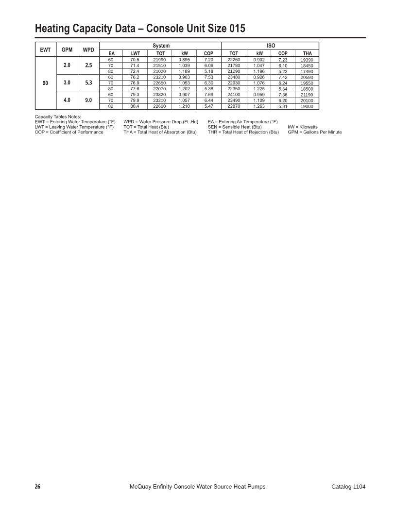
Heating Capacity Data – Console Unit Size 009
12.313.013.715.115.516.016.416.717.120.821.422.224.124.525.025.726.026.329.129.830.533.033.533.934.935.235.637.438.038.841.942.342.844.044.444.745.546.247.050.751.251.753.253.553.953.654.455.259.459.960.562.262.663.061.662.463.368.168.669.271.271.672.165.566.467.372.473.073.675.776.176.6
574056105520593057805670601058505700665065106380689067306570699068206650760074607300789077407560802078607670858084508290894087908600909089308740960094709310100209880969010220100609860106601053010370111801101010810114001121011010117901163011450123801219011970126501244012200123501219012010130101279012560132901306012810
0.5510.6330.7300.5520.6340.7300.5530.6340.7300.5600.6400.7310.5640.6430.7320.5650.6440.7330.5730.6530.7400.5760.6570.7440.5780.6590.7460.5850.6680.7550.5900.6730.7600.5910.6750.7620.5970.6840.7730.6000.6900.7800.6030.6920.7830.6060.6980.7920.6100.7050.8000.6120.7070.8030.6150.7130.8110.6170.7190.8190.6190.7210.8220.6170.7190.8190.6210.7240.8270.6220.7270.830
3.052.602.223.142.672.283.182.702.293.482.982.563.583.072.633.623.112.663.883.352.894.013.452.984.063.493.014.303.703.224.443.823.314.503.873.364.714.063.534.894.203.644.974.253.695.154.423.835.364.573.965.464.644.025.624.784.145.874.974.285.985.054.355.864.974.296.135.174.456.265.264.52
602058905800620060505940628061305980692067806650716070006840726071006930787077307570816080107830829081307950885087208560921090608880936092009010987097509580
10300101509970
104901033010130109401080010640114501128011090116701149011280120601190011730126501246012250129201271012470126301246012280132801306012830135601333013080
0.5530.6350.7320.5580.6390.7350.5640.6450.7400.5620.6420.7330.5690.6480.7380.5760.6550.7440.5750.6550.7420.5820.6620.7500.5890.6700.7570.5870.6700.7570.5950.6790.7660.6020.6860.7730.5990.6860.7750.6060.6950.7860.6140.7030.7940.6080.7010.7940.6160.7110.8060.6230.7180.8140.6170.7150.8130.6230.7240.8240.6300.7320.8330.6190.7210.8210.6270.7300.8320.6330.7380.841
3.192.722.323.262.772.373.262.782.363.603.092.663.683.162.723.693.182.734.013.462.994.113.543.064.123.563.084.423.813.314.533.913.394.553.933.414.834.163.624.984.283.715.014.303.745.274.523.925.444.654.035.494.694.065.734.884.235.955.044.356.015.084.395.975.064.386.205.244.526.285.294.55
4260390035304440406036704520413037005130476043605360497045505460506046306040566052406320593054906440604056006980660061807330693064807480706066107970758071508390797075108570814076609010859081509510905085709730925087501011096509170
10700101909670
10960104309890
10670102009700113101078010230116001104010470

18 McQuay Enfinity Console Water Source Heat Pumps Catalog 1104
Heating Capacity Data – Console Unit Size 009WPD
�.1
5.0
7.0
EA LWT TOT kW COP TOT kW COP THAEWT
90
System ISOGPM
1.1
1.8
�.�
607080607080607080
69.470.371.376.677.377.980.180.681.1
129501276012560136501342013160139501370013420
0.6210.7240.8270.6240.7300.8350.6250.7320.837
6.105.164.456.405.384.626.545.484.70
132201303012830139201369013430142201397013700
0.6230.7260.8290.6300.7360.8400.6360.7430.848
6.215.264.546.475.454.686.555.514.73
112501075010230119501139010810122501166011060
Capacity Tables Notes:EWT = Entering Water Temperature (°F) WPD = Water Pressure Drop (Ft. Hd) EA = Entering Air Temperature (°F)LWT = Leaving Water Temperature (°F) TOT = Total Heat (Btu) SEN = Sensible Heat (Btu) kW = KilowattsCOP = Coefficient of Performance THA = Total Heat of Absorption (Btu) THR = Total Heat of Rejection (Btu) GPM = Gallons Per Minute

19 McQuay Enfinity Console Water Source Heat Pumps Catalog 1104
WPD
1.�
�.�
�.�
1.�
�.�
�.�
1.�
�.�
�.�
1.�
�.�
�.�
1.�
�.�
�.�
1.�
�.�
�.�
1.�
�.�
�.�
1.�
�.�
�.�
758085758085758085758085758085758085758085758085758085758085758085758085758085758085758085758085758085758085758085758085758085758085758085758085
EA LWT TOT SEN kW EER TOT kW EER THREWT
30
40
50
60
70
80
85
90
System ISOGPM
1.�
2.4
�.�
1.�
2.4
�.�
1.�
2.4
�.�
1.�
2.4
�.�
1.�
2.4
�.�
1.�
2.4
�.�
1.�
2.4
�.�
1.�
2.4
�.�
636771636771636771636771636771636771636771636771636771636771636771636771636771636771636771636771636771636771636771636771636771636771636771636771
48.449.751.142.443.244.239.339.940.658.359.661.052.353.154.149.249.950.668.169.370.762.163.063.959.159.860.577.779.080.472.072.873.769.069.770.487.488.690.081.782.683.578.879.580.296.496.999.591.492.393.288.689.390.0101.0102.4104.295.997.198.093.394.294.8105.6106.9108.3100.7101.6102.898.198.899.7
142101534016580144701565016930146101577017070136801479015970139601510016340140801524016500131301420015340134201453015720135501467015890125601358014680128501392015070129901408015250119501293013990122601328014390124001344014570109601155013260116301261013670117701278013860105301152012880109301227013300111101243013490100901105012080104901151012920106701172013110
917093509510930094909700947095509720891090909250904092409410910093009480864088308990878089809150884090409220836085508720850087008880856087708950807082708440821084208600828084908680760074408160792081308320798082008390740076608010759079808170767080508250720074707700739076608030747077508100
0.2870.2590.2250.2240.1860.1400.1940.1520.1010.3990.3800.3580.3420.3140.2800.3140.2820.2430.5000.4920.4790.4490.4310.4090.4250.4030.3750.5930.5930.5900.5470.5390.5260.5250.5130.4960.6750.6850.6910.6360.6370.6340.6160.6140.6070.7460.7560.7810.7130.7240.7320.6960.7050.7080.7790.8000.8210.7480.7640.7760.7330.7450.7540.8080.8340.8580.7810.8000.8180.7680.7830.797
49.659.373.664.684.0
120.975.3
104.0169.334.338.944.640.948.158.344.854.067.926.328.932.029.933.738.531.936.542.421.222.924.923.525.928.624.727.430.817.718.920.219.320.922.720.121.924.014.715.317.016.317.418.716.918.119.613.514.415.714.616.117.115.216.717.912.513.314.113.414.415.813.915.016.4
1393015070163101419015370166501434015500167901341014510157001369014830160701381014970162301286013920150701315014250154401328014400156101228013310144101258013650148001272013800149701168012660137101198013010141101212013170143001068011280129801136012340134001150012500135901025011240126101066011990130201084012160132209820
1078011810102201124012640104001145012840
0.2920.2640.2300.2390.2010.1550.2280.1850.1350.4040.3850.3630.3570.3290.2950.3480.3160.2770.5050.4970.4840.4640.4470.4240.4590.4360.4090.5980.5980.5940.5620.5540.5410.5590.5470.5290.6800.6900.6960.6510.6520.6490.6500.6480.6400.7510.7610.7860.7280.7400.7470.7300.7380.7420.7830.8050.8260.7630.7790.7910.7670.7790.7880.8130.8390.8630.7960.8150.8330.8010.8170.831
47.857.170.859.376.4
107.362.983.6
124.933.237.743.338.445.154.439.747.458.725.528.031.128.331.936.428.933.038.220.522.224.222.424.727.322.825.228.317.218.419.718.419.921.718.720.322.314.214.816.515.616.717.915.716.918.313.114.015.314.015.416.514.115.616.812.112.913.712.813.815.213.014.015.4
149101596017080149801603017170150101605017180147501578016900148401589017020148801593017060145101555016650146401569016800146901574016860142201525016330143801542016520144401549016600138701488015950140601509016180141401518016280131001360015510136701469015770137601479015880127701382015250130801446015530132101457015660124201346014570127401382015280128801398015410
Cooling Capacity Data – Console Unit Size 012
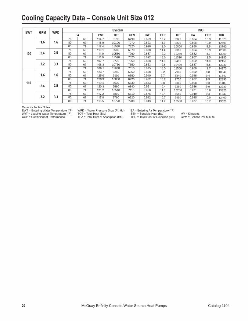
20 McQuay Enfinity Console Water Source Heat Pumps Catalog 1104
EWT
100
110
WPD
1.�
�.�
�.�
1.�
�.�
�.�
GPM
1.�
2.4
�.�
1.�
2.4
�.�
758085758085758085758085758085758085
636771636771636771636771636771636771
114.7116.0117.4110.1111.0111.9107.7108.3109.1123.7125.0126.3119.4120.3121.2117.2117.8118.5
EA LWT TOT SEN kW EER TOT kW EER THR System ISO
919010100110809580
10560115909770
107601183082509110
1003086309560
1054088109760
10770
679070707320697072607520705073507610635066506920653068407110661069207200
0.8590.8930.9260.8380.8670.8920.8280.8530.8750.8980.9400.9820.8830.9210.9560.8760.9120.943
10.711.312.011.412.213.011.812.613.59.29.7
10.29.8
10.411.010.110.711.4
89209830
108009310
10280113209490
104901156079808840975083609280
1026085409490
10500
0.8640.8980.9300.8540.8820.9070.8620.8870.9090.9020.9450.9870.8980.9360.9710.9100.9450.977
10.310.911.610.911.712.511.011.812.78.89.49.99.39.9
10.69.4
10.010.7
116701269013760120001306014180121501323014370108401184012890111801223013320113401240013520
Cooling Capacity Data – Console Unit Size 012
Capacity Tables Notes:EWT = Entering Water Temperature (°F) WPD = Water Pressure Drop (Ft. Hd) EA = Entering Air Temperature (°F)LWT = Leaving Water Temperature (°F) TOT = Total Heat (Btu) SEN = Sensible Heat (Btu) kW = KilowattsCOP = Coefficient of Performance THA = Total Heat of Absorption (Btu) THR = Total Heat of Rejection (Btu) GPM = Gallons Per Minute

�1 McQuay Enfinity Console Water Source Heat Pumps Catalog 1104
Heating Capacity Data – Console Unit Size 012
607080607080607080607080607080607080607080607080607080607080607080607080607080607080607080607080607080607080607080607080607080607080607080607080
WPD
1.�
�.�
�.�
1.�
�.�
�.�
1.�
�.�
�.�
1.�
�.�
�.�
1.�
�.�
�.�
1.�
�.�
�.�
1.�
�.�
�.�
1.�
�.�
�.�
EA LWT TOT kW COP TOT kW COP THAEWT
20
30
40
50
60
70
80
85
System ISOGPM
1.�
2.4
�.�
1.�
2.4
�.�
1.�
2.4
�.�
1.�
2.4
�.�
1.�
2.4
�.�
1.�
2.4
�.�
1.�
2.4
�.�
1.�
2.4
�.�
12.913.414.015.115.515.816.316.516.821.522.122.624.124.524.925.525.826.130.030.631.233.133.533.934.735.035.338.539.039.742.142.442.843.944.244.547.047.548.151.051.351.753.153.453.755.455.956.559.860.260.662.262.562.863.664.264.968.669.069.571.371.672.067.868.469.073.073.473.975.876.176.5
7450727071107680746072807780756073608660844082308920869084609050882085709890970094601021010010975010370101609880111501099010750115301136011120117201155011290124401231012090129001274012510131101295012720137901365013440143201416013940145801440014170151901503014830158001561015370161101590015640159001573015520165801636016090169001666016380
0.6450.7320.8320.6490.7360.8340.6510.7370.8350.6670.7530.8480.6720.7570.8510.6750.7590.8540.6930.7780.8710.7010.7850.8770.7040.7890.8800.7220.8090.9000.7300.8180.9090.7340.8230.9130.7490.8420.9350.7590.8520.9450.7630.8570.9510.7760.8750.9700.7850.8870.9850.7900.8930.9910.7990.9071.0090.8080.9181.0220.8120.9241.0290.8090.9211.0260.8190.9331.0400.8220.9381.047
3.382.912.503.462.972.563.503.002.583.803.292.843.893.362.913.933.402.944.183.653.184.273.733.254.313.773.294.533.983.504.634.073.584.684.113.624.874.283.794.984.383.885.034.433.925.214.574.065.344.684.145.414.734.195.574.864.315.734.984.415.815.044.455.765.014.435.935.144.536.025.204.58
773075407380795077407550805078307630893087208510919089608730932090908840
1016099709730
104901029010020106401043010160114201126011020118101163011390120001182011560127201258012370131701302012780133801323012990140601393013720145901443014210148601468014440154601530015100160801588015640163901617015910161801600015790168501663016370171701693016650
0.6500.7370.8370.6640.7510.8490.6850.7710.8690.6720.7570.8530.6880.7720.8660.7080.7930.8870.6980.7830.8760.7160.8000.8920.7380.8220.9130.7270.8130.9040.7450.8330.9240.7680.8560.9470.7540.8470.9390.7740.8680.9610.7960.8910.9850.7810.8800.9750.8000.9021.0000.8240.9261.0250.8040.9121.0130.8230.9331.0370.8460.9581.0630.8140.9251.0310.8340.9481.0550.8560.9721.081
3.483.002.583.503.022.613.442.982.573.893.372.923.923.402.953.853.362.924.263.733.254.293.763.294.223.723.264.614.053.574.644.093.614.584.043.584.944.353.864.984.403.904.924.353.865.284.644.125.344.694.165.284.644.135.634.924.365.724.984.425.674.944.385.825.074.495.925.144.545.885.114.51
575053204880596055005040606055905120689064305950713066606160726067806260804076107100835079007370849080407500922088108310958091608640976093208800
10440100309550
10860104409930110701063010120117101128010790122101175011240124601198011460130401257012060136301311012570139301339012820137301323012700143801382013240146901411013510

�� McQuay Enfinity Console Water Source Heat Pumps Catalog 1104
Heating Capacity Data – Console Unit Size 012WPD
1.�
�.�
�.�
EA LWT TOT kW COP TOT kW COP THAEWT
90
System ISOGPM
1.�
2.4
�.�
607080607080607080
71.872.573.277.377.878.380.380.781.1
166501645016210173601712016830177101744017120
0.8200.9341.0420.8280.9471.0570.8320.9511.062
5.955.164.556.145.294.666.235.374.72
169201672016480176401740017100179801771017400
0.8250.9391.0470.8440.9621.0720.8660.9851.095
6.015.214.616.125.294.676.085.274.65
144401390013350151401454013930154801485014210
Capacity Tables Notes:EWT = Entering Water Temperature (°F) WPD = Water Pressure Drop (Ft. Hd) EA = Entering Air Temperature (°F)LWT = Leaving Water Temperature (°F) TOT = Total Heat (Btu) SEN = Sensible Heat (Btu) kW = KilowattsCOP = Coefficient of Performance THA = Total Heat of Absorption (Btu) THR = Total Heat of Rejection (Btu) GPM = Gallons Per Minute

�� McQuay Enfinity Console Water Source Heat Pumps Catalog 1104
WPD
�.�
�.�
9.0
�.�
�.�
9.0
�.�
�.�
9.0
�.�
�.�
9.0
�.�
�.�
9.0
�.�
�.�
9.0
�.�
�.�
9.0
�.�
�.�
9.0
758085758085758085758085758085758085758085758085758085758085758085758085758085758085758085758085758085758085758085758085758085758085758085758085
EA LWT TOT SEN kW EER TOT kW EER THREWT
30
40
50
60
70
80
85
90
System ISOGPM
2.0
3.0
4.0
2.0
3.0
4.0
2.0
3.0
4.0
2.0
3.0
4.0
2.0
3.0
4.0
2.0
3.0
4.0
2.0
3.0
4.0
2.0
3.0
4.0
636771636771636771636771636771636771636771636771636771636771636771636771636771636771636771636771636771636771636771636771636771636771636771636771
50.652.254.044.045.246.440.541.442.460.061.663.253.654.755.850.251.052.069.270.872.563.164.265.459.860.761.678.479.981.672.573.674.869.470.271.287.789.190.782.083.084.279.079.880.697.298.599.991.592.593.588.689.490.2102.0103.2104.596.497.298.293.594.294.9106.7107.9109.2101.2102.1103.098.499.099.7
197402144023330204002231024420203702247024280186402031022040192102102022880192102111023180174601906020780179901982021640179901984021820163101779019410167101846020280167101846020410152901663018110155501712018880155501712018890144601563016950146001596017520146001596017520141101522016450142401547016920142401547016920137601485016010138701506016380138701506016380
129701327013650132901386014800132701407013960124101281013050126801311013390126801316013530118501222012540121001255012920121001256012960113201167012010115001196012350115001196012400108501119011510109701139011800109701139011810104901079011080105501092011290105501092011290103301062010900103901072011070103901072011070101801047010740102301056010870102301056010870
0.4000.3740.3440.3140.2710.2200.3150.2500.1790.5310.5180.5000.4650.4300.3970.4650.4180.3620.6450.6450.6400.5970.5710.5500.5970.5680.5280.7450.7560.7630.7110.6990.6880.7110.6990.6760.8340.8530.8720.8110.8130.8080.8110.8130.8070.9080.9370.9650.8930.9090.9180.8930.9090.9180.9400.9741.0060.9280.9510.9670.9280.9510.9670.9671.0081.0450.9590.9891.0120.9590.9891.012
49.457.267.764.982.2111.064.689.7
135.335.139.244.141.348.957.641.350.564.127.129.532.430.234.739.330.234.941.421.923.525.423.526.429.523.526.430.218.319.520.819.221.123.419.221.123.415.916.717.616.317.519.116.317.519.115.015.616.315.316.317.515.316.317.514.214.715.314.515.216.214.515.216.2
194602116023050201202204024150201002220024000183702003021770189302074022600189302084022900171901879020500177201954021370177201957021540160401752019140164301818020010164301818020140150101636017830152701684018600152701684018620141801536016680143301569017250143301569017250138401495016170139601520016640139601520016640134901458015730136001479016110136001479016110
0.4070.3820.3520.3370.2940.2430.3680.3030.2320.5390.5250.5070.4880.4530.4200.5170.4710.4140.6520.6530.6480.6200.5940.5730.6490.6200.5800.7520.7630.7700.7340.7220.7110.7640.7510.7290.8410.8600.8790.8340.8360.8310.8640.8650.8590.9150.9440.9720.9160.9320.9410.9460.9620.9710.9470.9811.0140.9510.9740.9900.9811.0041.0200.9741.0151.0520.9821.0121.0351.0111.0411.064
47.855.465.559.774.999.454.673.3
103.534.138.242.938.845.853.836.644.355.326.428.831.728.632.937.327.331.537.121.323.024.822.425.228.121.524.227.617.919.020.318.320.222.417.719.521.715.516.317.215.616.818.315.216.317.814.615.216.014.715.616.814.215.116.313.814.415.013.814.615.613.414.215.1
208202243024230212102299024920211902305025150201302176023430204902219023940204902224024120193102091022610196902143023180196902145023290184701998021630187602047022260187602047022350177301913020660179201949021230179201949021250171201839019800172301863020230172301863020230168801810019420169701828019770169701828019770166101783019100166901798019370166901798019370
Cooling Capacity Data – Console Unit Size 015

24 McQuay Enfinity Console Water Source Heat Pumps Catalog 1104
EWT
100
110
WPD
�.�
�.�
9.0
�.�
�.�
9.0
GPM
2.0
3.0
4.0
2.0
3.0
4.0
758085758085758085758085758085758085
636771636771636771636771636771636771
116.2117.4118.6110.8111.7112.6108.1108.8109.4125.5126.7127.9120.4121.2122.1117.8118.4119.1
EA LWT TOT SEN kW EER TOT kW EER THR System ISO
130501408015180131101425015480131101425015480123101328014320123201340014570123201340014570
987010170104409900
10240105509900
102401055095609860
1014095609910
1023095609910
10230
1.0101.0611.1101.0071.0501.0881.0071.0501.0881.0421.1001.1571.0421.0951.1451.0421.0951.145
12.913.313.713.013.614.213.013.614.211.812.112.411.812.212.711.812.212.7
127701380014900128401398015210128401398015210120301300014040120501313014300120501313014300
1.0181.0681.1171.0301.0731.1111.0601.1021.1401.0491.1071.1651.0651.1181.1681.0941.1471.197
12.612.913.312.513.013.712.112.713.311.511.712.111.311.712.211.011.411.9
160201722018470160801736018710160801736018710153701653017750153901664017970153901664017970
Cooling Capacity Data – Console Unit Size 015
Capacity Tables Notes:EWT = Entering Water Temperature (°F) WPD = Water Pressure Drop (Ft. Hd) EA = Entering Air Temperature (°F)LWT = Leaving Water Temperature (°F) TOT = Total Heat (Btu) SEN = Sensible Heat (Btu) kW = KilowattsCOP = Coefficient of Performance THA = Total Heat of Absorption (Btu) THR = Total Heat of Rejection (Btu) GPM = Gallons Per Minute
�� McQuay Enfinity Console Water Source Heat Pumps Catalog 1104
607080607080607080607080607080607080607080607080607080607080607080607080607080607080607080607080607080607080607080607080607080607080607080607080
WPD
�.�
�.�
9.0
�.�
�.�
9.0
�.�
�.�
9.0
�.�
�.�
9.0
�.�
�.�
9.0
�.�
�.�
9.0
�.�
�.�
9.0
�.�
�.�
9.0
EA LWT TOT kW COP TOT kW COP THAEWT
20
30
40
50
60
70
80
85
System ISOGPM
2.0
3.0
4.0
2.0
3.0
4.0
2.0
3.0
4.0
2.0
3.0
4.0
2.0
3.0
4.0
2.0
3.0
4.0
2.0
3.0
4.0
2.0
3.0
4.0
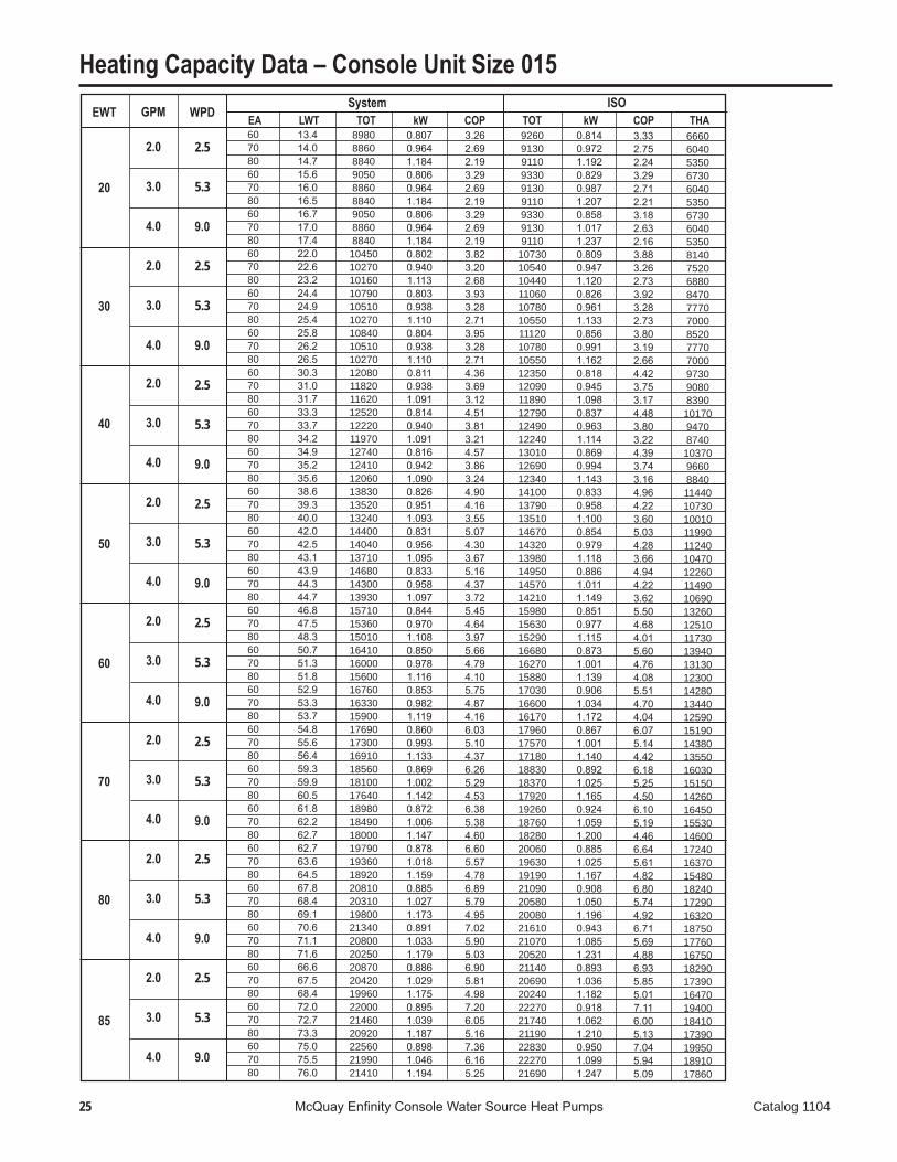
Heating Capacity Data – Console Unit Size 015
13.414.014.715.616.016.516.717.017.422.022.623.224.424.925.425.826.226.530.331.031.733.333.734.234.935.235.638.639.340.042.042.543.143.944.344.746.847.548.350.751.351.852.953.353.754.855.656.459.359.960.561.862.262.762.763.664.567.868.469.170.671.171.666.667.568.472.072.773.375.075.576.0
898088608840905088608840905088608840104501027010160107901051010270108401051010270120801182011620125201222011970127401241012060138301352013240144001404013710146801430013930157101536015010164101600015600167601633015900176901730016910185601810017640189801849018000197901936018920208102031019800213402080020250208702042019960220002146020920225602199021410
0.8070.9641.1840.8060.9641.1840.8060.9641.1840.8020.9401.1130.8030.9381.1100.8040.9381.1100.8110.9381.0910.8140.9401.0910.8160.9421.0900.8260.9511.0930.8310.9561.0950.8330.9581.0970.8440.9701.1080.8500.9781.1160.8530.9821.1190.8600.9931.1330.8691.0021.1420.8721.0061.1470.8781.0181.1590.8851.0271.1730.8911.0331.1790.8861.0291.1750.8951.0391.1870.8981.0461.194
3.262.692.193.292.692.193.292.692.193.823.202.683.933.282.713.953.282.714.363.693.124.513.813.214.573.863.244.904.163.555.074.303.675.164.373.725.454.643.975.664.794.105.754.874.166.035.104.376.265.294.536.385.384.606.605.574.786.895.794.957.025.905.036.905.814.987.206.055.167.366.165.25
926091309110933091309110933091309110
107301054010440110601078010550111201078010550123501209011890127901249012240130101269012340141001379013510146701432013980149501457014210159801563015290166801627015880170301660016170179601757017180188301837017920192601876018280200601963019190210902058020080216102107020520211402069020240222702174021190228302227021690
0.8140.9721.1920.8290.9871.2070.8581.0171.2370.8090.9471.1200.8260.9611.1330.8560.9911.1620.8180.9451.0980.8370.9631.1140.8690.9941.1430.8330.9581.1000.8540.9791.1180.8861.0111.1490.8510.9771.1150.8731.0011.1390.9061.0341.1720.8671.0011.1400.8921.0251.1650.9241.0591.2000.8851.0251.1670.9081.0501.1960.9431.0851.2310.8931.0361.1820.9181.0621.2100.9501.0991.247
3.332.752.243.292.712.213.182.632.163.883.262.733.923.282.733.803.192.664.423.753.174.483.803.224.393.743.164.964.223.605.034.283.664.944.223.625.504.684.015.604.764.085.514.704.046.075.144.426.185.254.506.105.194.466.645.614.826.805.744.926.715.694.886.935.855.017.116.005.137.045.945.09
666060405350673060405350673060405350814075206880847077707000852077707000973090808390
1017094708740
1037096608840114401073010010119901124010470122601149010690132601251011730139401313012300142801344012590151901438013550160301515014260164501553014600172401637015480182401729016320187501776016750182901739016470194001841017390199501891017860
�� McQuay Enfinity Console Water Source Heat Pumps Catalog 1104
Heating Capacity Data – Console Unit Size 015WPD
�.�
�.�
9.0
EA LWT TOT kW COP TOT kW COP THAEWT
90
System ISOGPM
2.0
3.0
4.0
607080607080607080
70.571.472.476.276.977.679.379.980.4
219902151021020232102265022070238202321022600
0.8951.0391.1890.9031.0531.2020.9071.0571.210
7.206.065.187.536.305.387.696.445.47
222602178021290234802293022350241002349022870
0.9021.0471.1960.9261.0761.2250.9591.1091.263
7.236.105.227.426.245.347.366.205.31
193901845017490205901955018500211902010019000
Capacity Tables Notes:EWT = Entering Water Temperature (°F) WPD = Water Pressure Drop (Ft. Hd) EA = Entering Air Temperature (°F)LWT = Leaving Water Temperature (°F) TOT = Total Heat (Btu) SEN = Sensible Heat (Btu) kW = KilowattsCOP = Coefficient of Performance THA = Total Heat of Absorption (Btu) THR = Total Heat of Rejection (Btu) GPM = Gallons Per Minute
27 McQuay Enfinity Console Water Source Heat Pumps Catalog 1104
WPD
�.�
7.7
1�.�
�.�
7.7
1�.�
�.�
7.7
1�.�
�.�
7.7
1�.�
�.�
7.7
1�.�
�.�
7.7
1�.�
�.�
7.7
1�.�
�.�
7.7
1�.�
758085758085758085758085758085758085758085758085758085758085758085758085758085758085758085758085758085758085758085758085758085758085758085758085
EA LWT TOT SEN kW EER TOT kW EER THREWT
30
40
50
60
70
80
85
90
System ISOGPM
2.4
�.�
4.8
2.4
�.�
4.8
2.4
�.�
4.8
2.4
�.�
4.8
2.4
�.�
4.8
2.4
�.�
4.8
2.4
�.�
4.8
2.4
�.�
4.8
636771636771636771636771636771636771636771636771636771636771636771636771636771636771636771636771636771636771636771636771636771636771636771636771
48.449.751.042.343.143.939.239.840.458.259.560.852.153.053.849.149.750.467.969.170.462.062.863.759.059.660.277.578.780.071.772.573.468.869.470.087.088.289.581.482.283.178.579.179.896.597.798.991.191.892.788.388.989.5101.3102.4103.695.996.797.593.293.794.4106.1107.1108.3100.7101.5102.398.098.699.2
208502249024260210802282024620210802282024680199702154023220201802185023600201802185023650190802058022190192802088022580192802088022610181801961021130183601989021520183601989021540172901864020090174301889020450174301889020450163801766019030164901788019360164901788019360159201717018500160201737018810160201737018810154601668017970155501685018260155501685018260
134901378014040136201394014170136201394014200130001328013520131201344013700131201344013720125301280013040126401295013210126401295013230120701234012570121601247012740121601247012750115901187012120116701199012280116701199012280111101140011650111701150011790111701150011790108801117011420109301126011550109301126011550106401093011190106801101011310106801101011310
0.5360.4900.4320.4510.3610.2730.4510.3610.2480.7060.6850.6540.6410.5830.5220.6410.5830.5040.8440.8430.8320.7950.7620.7240.7950.7620.7140.9530.9660.9770.9170.9080.8880.9170.9080.8851.0471.0691.0891.0191.0231.0211.0191.0231.0211.1361.1621.1891.1141.1251.1331.1141.1251.1331.1811.2081.2371.1621.1741.1851.1621.1741.1851.2281.2541.2831.2111.2231.2361.2111.2231.236
38.945.956.246.763.190.246.763.199.428.331.435.531.537.545.231.537.546.922.624.426.724.327.431.224.327.431.719.120.321.620.021.924.220.021.924.316.517.418.417.118.520.017.118.520.014.415.216.014.815.917.114.815.917.113.514.215.013.814.815.913.814.815.912.613.314.012.813.814.812.813.814.8
205802222023990208002254024350208002254024410197002127022940199102157023330199102157023380188102030021920190102060022300190102060022340179101934020860180801961021250180801961021260170101837019810171601861020180171601861020180161001739018760162201760019090162201760019090156501690018230157501709018540157501709018540151901640017700152701658017990152701658017990
0.5420.4960.4380.4680.3790.2900.4910.4010.2880.7120.6910.6590.6580.6000.5390.6810.6230.5440.8490.8480.8380.8120.7800.7420.8350.8020.7540.9580.9720.9820.9350.9250.9060.9570.9480.9251.0521.0741.0951.0371.0411.0381.0591.0631.0611.1411.1681.1951.1321.1431.1511.1541.1651.1731.1861.2141.2421.1791.1921.2031.2021.2141.2251.2331.2601.2891.2291.2411.2531.2511.2631.276
38.044.854.844.459.583.842.456.284.727.730.834.830.235.943.329.234.643.022.223.926.223.426.430.122.825.729.618.719.921.219.321.223.518.920.723.016.217.118.116.517.919.416.217.519.014.114.915.714.315.416.614.115.116.313.213.914.713.414.315.413.114.115.112.313.013.712.413.414.412.213.114.1
223702386025440223302377025290223302377025270220302353025100220302351025060220302351025060215702306024640216202311024680216202311024690210202248024040210802258024150210802258024150204102184023350204702194023500204702194023500197802115022610198302125022760198302125022760194702080022220195102089022370195102089022370191502045021840191902053021970191902053021970
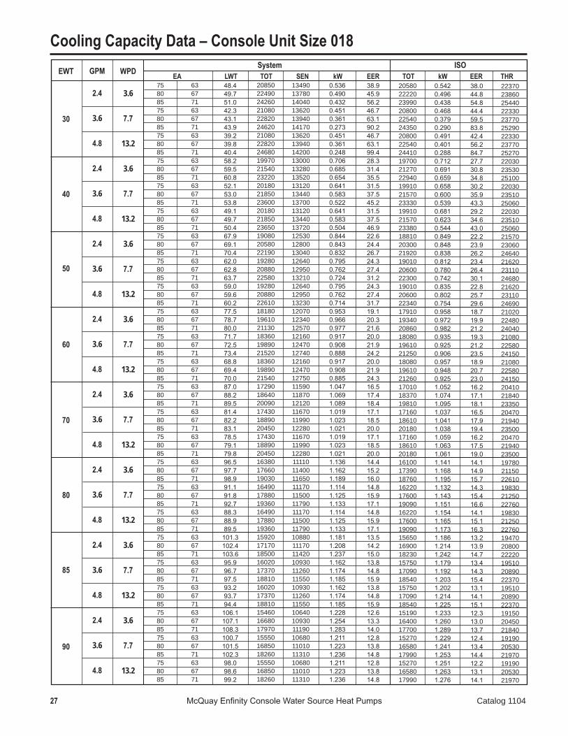
Cooling Capacity Data – Console Unit Size 018

28 McQuay Enfinity Console Water Source Heat Pumps Catalog 1104
EWT
100
110
WPD
�.�
7.7
1�.�
�.�
7.7
1�.�
GPM
2.4
�.�
4.8
2.4
�.�
4.8
758085758085758085758085758085758085
636771636771636771636771636771636771
115.6116.6117.7110.4111.1111.9107.8108.3108.9125.2126.1127.1120.1120.8121.5117.6118.1118.6
EA LWT TOT SEN kW EER TOT kW EER THR System ISO
145401568016900145901582017140145901582017140136101467015800136401477016000136401477016000
10160104601073010180105201083010180105201083096909980
102509700
10020103409700
1002010340
1.3371.3551.3811.3251.3281.3381.3251.3281.3381.4731.4771.4921.4671.4541.4541.4671.4541.454
10.911.612.211.011.912.811.011.912.89.29.9
10.69.3
10.211.09.3
10.211.0
142701541016620143201555016870143201555016870133401440015530133601450015730133601450015730
1.3421.3611.3861.3421.3461.3561.3651.3681.3781.4791.4821.4981.4841.4711.4711.5061.4941.493
10.611.312.010.711.612.410.511.412.29.09.7
10.49.09.9
10.78.99.7
10.5
185701977021060185801982021170185801982021170180701914020320180701916020390180701916020390
Cooling Capacity Data – Console Unit Size 018
Capacity Tables Notes:EWT = Entering Water Temperature (°F) WPD = Water Pressure Drop (Ft. Hd) EA = Entering Air Temperature (°F)LWT = Leaving Water Temperature (°F) TOT = Total Heat (Btu) SEN = Sensible Heat (Btu) kW = KilowattsCOP = Coefficient of Performance THA = Total Heat of Absorption (Btu) THR = Total Heat of Rejection (Btu) GPM = Gallons Per Minute

29 McQuay Enfinity Console Water Source Heat Pumps Catalog 1104
607080607080607080607080607080607080607080607080607080607080607080607080607080607080607080607080607080607080607080607080607080607080607080607080
WPD
�.�
7.7
1�.�
�.�
7.7
1�.�
�.�
7.7
1�.�
�.�
7.7
1�.�
�.�
7.7
1�.�
�.�
7.7
1�.�
�.�
7.7
1�.�
�.�
7.7
1�.�
EA LWT TOT kW COP TOT kW COP THAEWT
20
30
40
50
60
70
80
85
System ISOGPM
2.4
�.�
4.8
2.4
�.�
4.8
2.4
�.�
4.8
2.4
�.�
4.8
2.4
�.�
4.8
2.4
�.�
4.8
2.4
�.�
4.8
2.4
�.�
4.8
Heating Capacity Data – Console Unit Size 018
12.813.113.515.015.315.516.216.416.621.521.922.324.224.424.725.625.826.030.130.631.133.233.533.934.835.135.338.739.239.742.242.542.944.044.344.647.147.748.351.151.551.953.253.553.855.556.156.859.960.460.962.362.663.063.864.565.268.769.269.871.371.872.267.968.769.473.173.674.275.976.376.7
115601130011090118801160011360120301174011480132901300012720136701334013050138501352013210150701474014410155301516014800157501536014990169101653016170174601705016650177301730016880188401843018020194901903018580198101934018870208602041019960216502114020650220202150020980229902250022020239002336022830243602380023230240802359023100250802452023970255702499024410
1.0011.0551.1311.0171.0701.1461.0241.0771.1531.0731.1331.2131.0851.1461.2261.0901.1521.2331.1211.1911.2781.1311.2031.2911.1351.2081.2981.1561.2381.3351.1651.2511.3501.1691.2571.3571.1861.2831.3921.1951.2971.4101.2011.3051.4191.2181.3321.4551.2331.3531.4801.2411.3631.4921.2621.3951.5331.2861.4241.5681.2991.4401.5861.2911.4331.5801.3211.4691.6201.3371.4891.642
3.383.142.873.423.182.903.443.192.923.633.363.073.693.413.123.723.443.143.943.623.304.023.693.364.063.723.384.293.913.554.393.993.614.444.033.644.664.213.794.784.303.864.834.343.905.014.494.025.144.584.095.204.624.125.334.734.215.444.814.275.494.844.295.464.824.285.564.894.335.604.924.35
118301158011360121501188011630123001201011760135701327013000139401362013320141201379013480153501501014690158001543015080160201563015260171901680016440177401732016920180101757017150191201870018290197701931018860200901961019140211302068020240219202142020920223002177021250232602278022290241702364023110246402407023500243502387023370253502480024240258402526024680
1.0071.0601.1371.0341.0881.1641.0641.1171.1931.0781.1381.2181.1021.1631.2441.1301.1921.2731.1261.1971.2841.1481.2211.3091.1751.2481.3381.1611.2441.3401.1821.2681.3671.2091.2961.3971.1911.2881.3971.2131.3151.4271.2401.3451.4591.2241.3381.4611.2511.3701.4971.2811.4031.5321.2681.4001.5381.3041.4421.5851.3391.4801.6261.2961.4381.5851.3381.4871.6381.3771.5291.682
3.443.202.933.443.202.933.393.152.893.693.413.123.703.433.143.663.393.103.993.673.354.033.703.373.993.673.344.333.963.594.404.003.624.363.973.604.704.253.834.774.303.874.744.273.845.064.534.065.134.584.095.104.554.065.374.774.255.434.804.275.394.764.245.504.864.325.554.894.335.504.844.30
876083607930904086108150917087308260
1029098209310
10620101209590
10790102809730119201138010810123501176011150125501195011320136601304012390141801352012820144401375013030155001480014070161201536014580164301564014840174201663015820181601731016440185201763016730194201854017650202601931018360206901970018700204301952018590213402034019330217802075019710

30 McQuay Enfinity Console Water Source Heat Pumps Catalog 1104
Heating Capacity Data – Console Unit Size 018WPD
�.�
7.7
1�.�
EA LWT TOT kW COP TOT kW COP THAEWT
90
System ISOGPM
2.4
�.�
4.8
607080607080607080
72.072.873.677.578.178.680.480.981.3
252102470024190262902572025140268202621025610
1.3251.4761.6321.3631.5211.6811.3831.5441.707
5.574.904.345.654.954.385.684.974.39
254902498024470265702599025410270902649025880
1.3301.4821.6371.3801.5381.6981.4231.5841.747
5.614.944.385.644.954.385.584.904.34
214602050019530224302138020330229002181020720
Capacity Tables Notes:EWT = Entering Water Temperature (°F) WPD = Water Pressure Drop (Ft. Hd) EA = Entering Air Temperature (°F)LWT = Leaving Water Temperature (°F) TOT = Total Heat (Btu) SEN = Sensible Heat (Btu) kW = KilowattsCOP = Coefficient of Performance THA = Total Heat of Absorption (Btu) THR = Total Heat of Rejection (Btu) GPM = Gallons Per Minute
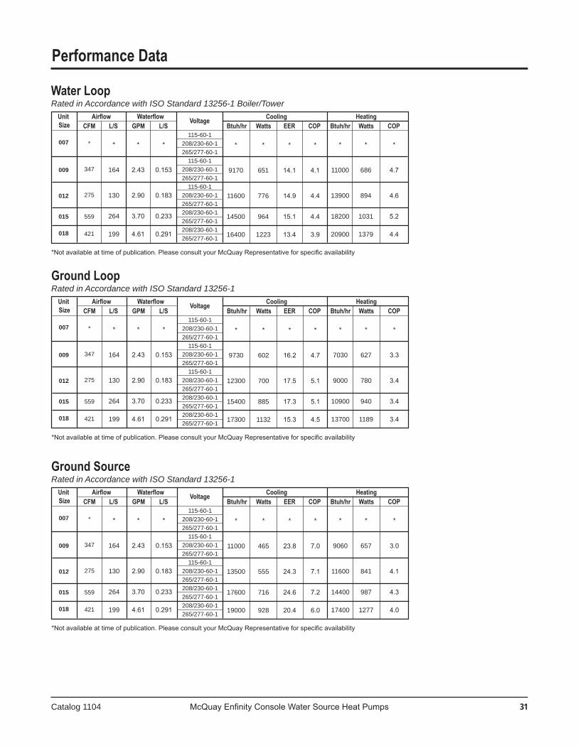
Catalog 1104 McQuay Enfinity Console Water Source Heat Pumps �1
Performance Data
Unit Airflow Waterflow Voltage Cooling Heating Size CFM L/S GPM L/S Btuh/hr Watts EER COP Btuh/hr Watts COP
115-60-1208/230-60-1265/277-60-1
115-60-1208/230-60-1265/277-60-1
115-60-1208/230-60-1265/277-60-1 208/230-60-1265/277-60-1208/230-60-1265/277-60-1
Water LoopRated in Accordance with ISO Standard 13256-1 Boiler/Tower
*Not available at time of publication. Please consult your McQuay Representative for specific availability
007
009
012
015 018
*
347
275
559
421
*
164
130
264
199
*
2.43
2.90
3.70
4.61
*
0.153
0.183
0.233
0.291
*
9170
11600
14500
16400
*
651
776
964
1223
*
14.1
14.9
15.1
13.4
*
4.1
4.4
4.4
3.9
*
11000
13900
18200
20900
*
686
894
1031
1379
*
4.7
4.6
5.2
4.4
Unit Airflow Waterflow Voltage Cooling Heating Size CFM L/S GPM L/S Btuh/hr Watts EER COP Btuh/hr Watts COP
115-60-1208/230-60-1265/277-60-1
115-60-1208/230-60-1265/277-60-1
115-60-1208/230-60-1265/277-60-1 208/230-60-1265/277-60-1208/230-60-1265/277-60-1
Ground LoopRated in Accordance with ISO Standard 13256-1
*Not available at time of publication. Please consult your McQuay Representative for specific availability
007
009
012
015 018
*
347
275
559
421
*
164
130
264
199
*
2.43
2.90
3.70
4.61
*
0.153
0.183
0.233
0.291
*
9730
12300
15400
17300
*
602
700
885
1132
*
16.2
17.5
17.3
15.3
*
4.7
5.1
5.1
4.5
*
7030
9000
10900
13700
*
627
780
940
1189
*
3.3
3.4
3.4
3.4
Unit Airflow Waterflow Voltage Cooling Heating Size CFM L/S GPM L/S Btuh/hr Watts EER COP Btuh/hr Watts COP
115-60-1208/230-60-1265/277-60-1
115-60-1208/230-60-1265/277-60-1
115-60-1208/230-60-1265/277-60-1 208/230-60-1265/277-60-1208/230-60-1265/277-60-1
Ground SourceRated in Accordance with ISO Standard 13256-1
*Not available at time of publication. Please consult your McQuay Representative for specific availability
007
009
012
015 018
*
347
275
559
421
*
164
130
264
199
*
2.43
2.90
3.70
4.61
*
0.153
0.183
0.233
0.291
*
11000
13500
17600
19000
*
465
555
716
928
*
23.8
24.3
24.6
20.4
*
7.0
7.1
7.2
6.0
*
9060
11600
14400
17400
*
657
841
987
1277
*
3.0
4.1
4.3
4.0
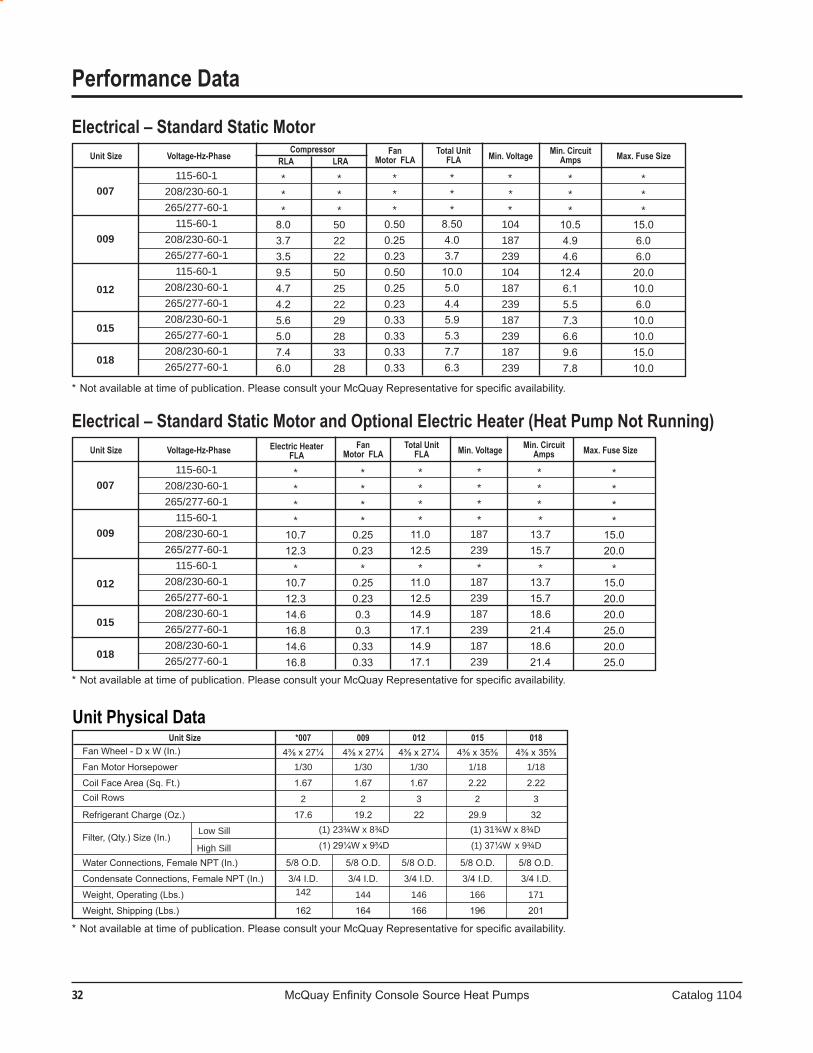
�� McQuay Enfinity Console Source Heat Pumps Catalog 1104
Unit Size *007 009 012 015 018 Fan Wheel - D x W (In.) 4⅜ x 27¼ 4⅜ x 27¼ 4⅜ x 27¼ 4⅜ x 35⅜ 4⅜ x 35⅜ Fan Motor Horsepower 1/30 1/30 1/30 1/18 1/18
Coil Face Area (Sq. Ft.) 1.67 1.67 1.67 2.22 2.22 Coil Rows 2 2 3 2 3 Refrigerant Charge (Oz.) 17.6 19.2 22 29.9 32
Low Sill (1) 23¾W x 8¾D (1) 31¾W x 8¾D
Filter, (Qty.) Size (In.) High Sill (1) 29¼W x 9¾D (1) 37¼W x 9¾D
Water Connections, Female NPT (In.) 5/8 O.D. 5/8 O.D. 5/8 O.D. 5/8 O.D. 5/8 O.D. Condensate Connections, Female NPT (In.) 3/4 I.D. 3/4 I.D. 3/4 I.D. 3/4 I.D. 3/4 I.D.
Weight, Operating (Lbs.) 142 144 146 166 171
Weight, Shipping (Lbs.) 162 164 166 196 201
Unit Size Voltage-Hz-Phase Electric Heater Fan Total Unit Min. Voltage Min. Circuit Max. Fuse Size
FLA Motor FLA FLA Amps
Unit Size Voltage-Hz-Phase Compressor Fan Total Unit Min. Voltage Min. Circuit Max. Fuse Size
RLA LRA Motor FLA FLA Amps
***
50222250252229283328
****
15.020.0
*15.020.020.025.020.025.0
007
009
012
015
018
Electrical – Standard Static Motor
115-60-1208/230-60-1265/277-60-1
115-60-1208/230-60-1265/277-60-1
115-60-1208/230-60-1265/277-60-1208/230-60-1265/277-60-1208/230-60-1265/277-60-1
***
10.54.94.612.46.15.57.36.69.67.8
***
0.500.250.230.500.250.230.330.330.330.33
***
8.03.73.59.54.74.25.65.07.46.0
***
8.504.03.710.05.04.45.95.37.76.3
* *
* 104187239104187239187239187239
***
15.06.06.020.010.06.010.010.015.010.0
* Not available at time of publication. Please consult your McQuay Representative for specific availability.
007
009
012
015
018
Electrical – Standard Static Motor and Optional Electric Heater (Heat Pump Not Running)
115-60-1208/230-60-1265/277-60-1
115-60-1208/230-60-1265/277-60-1
115-60-1208/230-60-1265/277-60-1208/230-60-1265/277-60-1208/230-60-1265/277-60-1
****
11.012.5
*11.012.514.917.114.917.1
****
10.712.3
*10.712.314.616.814.616.8
****
0.250.23
*0.250.230.30.30.330.33
****
187239
*187239187239187239
* * *
*13.715.7
*13.715.718.621.418.621.4
* Not available at time of publication. Please consult your McQuay Representative for specific availability.
Unit Physical Data
* Not available at time of publication. Please consult your McQuay Representative for specific availability.
Performance Data

Catalog 1104 McQuay Enfinity Console Water Source Heat Pumps ��
Standard Range Geothermal Range Units Units Cooling Heating Cooling Heating Min. Entering... Water 1,2 13ºC 13ºC -1ºC -6ºC Normal Entering Water 29ºC 21ºC 25ºC 4ºC Max Entering Water 43ºC 32ºC 43ºC 32ºC
Standard Range Geothermal Range Units Units Cooling Heating Cooling Heating Min. Entering Water 1,2 55ºF 55ºF 30ºF 20ºF Normal Entering Water 85ºF 70ºF 77ºF 40ºF Max Entering Water 110ºF 90ºF 110ºF 90ºF
Standard Range Geothermal Range Units Units Cooling Heating Cooling Heating Min. Ambient Air 10ºC 10ºC 5ºC 5ºC Normal Ambient Air 27ºC 21ºC 27ºC 21ºC Max Ambient Air 38ºC 29ºC 38ºC 29ºC Min. Entering Air 1,2 10ºC 10ºC 10ºC 5ºC Normal Entering Air db/wb 27/19ºC 21ºC 27/19ºC 21ºC Max Entering Air db/wb 1,2 38/28ºC 27ºC 38/28ºC 27ºC
Standard Range Geothermal Range Units Units Cooling Heating Cooling Heating Min. Ambient Air 50ºF 50ºF 40ºF 40ºF Normal Ambient Air 80ºF 70ºF 80ºF 70ºF Max Ambient Air 100ºF 85ºF 100ºF 85ºF Min. Entering Air 1,2 50ºF 50ºF 50ºF 40ºF Normal Entering Air db/wb 80/67ºF 70ºF 80/67ºF 70ºF Max Entering Air db/wb 1,2 100/83ºF 80ºF 100/83ºF 80ºF
Unit Fan Cooling Heating Size Speed SCFM L/s SCFM L/s
007 Low * * * *
High * * * *
009 Low 258 122 264 124
High 347 164 355 167
012 Low 243 115 256 121
High 275 130 300 142
015 Low 340 160 376 177
High 559 265 619 292
018 Low 316 149 338 160
High 421 199 450 212
Performance DataEnvironment
This equipment is designed for indoor installation only. Shelteredlocationssuchasattics,garages,etc.,generallywill not provide sufficient protection against extremes in temperature and/or humidity, and equipment performance, reliability,andservicelifemaybeadverselyaffected.
Power SupplyA voltage variation of +/-10% of nameplate voltage is
acceptable.Three-phasesystemimbalanceshallnotexceed2%.
Additional Information for Initial Start-Up Only
Standard Range Units:Unitsaredesignedtostartinanambientof50ºF(10ºC),
with entering air at 50ºF (10ºC), with entering water at 70ºF (21ºC), with both air and water at the flow rates used in the ISO 13256-1 rating test, for initial start-up in winter.
Note: This is not a normal or continuous operating condition. It is assumed that such a start-up is for the purpose of bringing the building space up to occupancy temperature.
Geothermal Range Units:Geothermalrangeheatpumpconditionersaredesigned
tostartinanambientof40ºF(5ºC),withenteringairat40ºF(5ºC),withenteringwaterat40ºF(5ºC),withbothairand water at the flow rates used in the ISO 13256-1 rating test,forinitialstart-upinwinter.
Note: This is not a normal or continuous operating condition. It is assumed that such a start-up is for the purpose of bringing the building space up to occupancy temperature.
Air Limits - °F (English units)
Air Limits - °C (SI units)
Water - °F (English units)
Water - °C (SI units)
1 At ARI flow rate� Maximum and minimum values may not be combined. If one value is
at maximum or minimum, the other two conditions may not exceed the normal condition for standard units. Extended range units may combine any two maximum conditions, but not more than two, with all other conditions being normal conditions.
Operating Limits
Fan PerformanceAirflow Vs. CFM - Standard Static Motor
*Not available at time of publication. Please consult your McQuay Representative for specific availability
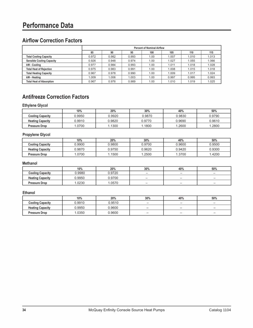
34 McQuay Enfinity Console Source Heat Pumps Catalog 1104
10% 20% 30% 40% 50% Cooling Capacity 0.9910 0.9510 – – – Heating Capacity 0.9950 0.9600 – – – Pressure Drop 1.0350 0.9600 – – –
10% 20% 30% 40% 50% Cooling Capacity 0.9980 0.9720 – – – Heating Capacity 0.9950 0.9700 – – – Pressure Drop 1.0230 1.0570 – – –
10% 20% 30% 40% 50% Cooling Capacity 0.9900 0.9800 0.9700 0.9600 0.9500 Heating Capacity 0.9870 0.9750 0.9620 0.9420 0.9300 Pressure Drop 1.0700 1.1500 1.2500 1.3700 1.4200
10% 20% 30% 40% 50% Cooling Capacity 0.9950 0.9920 0.9870 0.9830 0.9790 Heating Capacity 0.9910 0.9820 0.9770 0.9690 0.9610 Pressure Drop 1.0700 1.1300 1.1800 1.2600 1.2800
Percent of Nominal Airflow 85 90 95 100 105 110 115 Total Cooling Capacity 0.972 0.982 0.993 1.00 1.007 1.010 1.013 Sensible Cooling Capacity 0.926 0.948 0.974 1.00 1.027 1.055 1.066 kW - Cooling 0.977 0.984 0.993 1.00 1.011 1.018 1.028 Total Heat of Rejection 0.975 0.983 0.991 1.00 1.008 1.015 1.018 Total Heating Capacity 0.967 0.978 0.990 1.00 1.009 1.017 1.024 kW - Heating 1.009 1.006 1.003 1.00 0.997 0.995 0.993 Total Heat of Absorption 0.967 0.976 0.989 1.00 1.010 1.019 1.025
Performance Data
Airflow Correction Factors
Antifreeze Correction FactorsEthylene Glycol
Propylene Glycol
Methanol
Ethanol
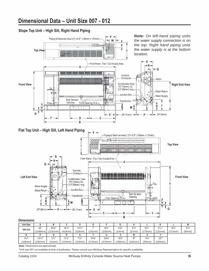
Catalog 1104 McQuay Enfinity Console Water Source Heat Pumps ��
N P Q R S T U V W X Y
4¼" 10¼" 13/5" 5¼" 7½" 10¾" 18¾" 6⅝" 6" 3¼" 25" (108mm) (260mm) (41mm) (134mm) (192mm) (273mm) (476mm) (168mm) (152mm) (83mm) (635mm)
Unit Size A B C D E F G H J K L M
*007-012 46" 45⅜" 16½" 12½" 7" 8⅞" 0.6" 2¼" 6⅞" 51/5" 6¾" 3½"
(1168mm) (1153mm) (418mm) (318mm) (181mm) (225mm) (14mm) (57mm) (175mm) (132mm) (172mm) (90mm)
Slope Top Unit – High Sill, Right Hand Piping
Dimensional Data – Unit Size 007 - 012
Dimensions
Note: Dimensions are approximate*Unit size 007 not available at time of publication. Please consult your McQuay Representative for specific availability.
Flat Top Unit – High Sill, Left Hand Piping
Top View
Right End ViewFront View
Top View
Left End View Front View
Note: On left-hand piping units the water supply connection is on the top. Right hand piping units the water supply is at the bottom location.
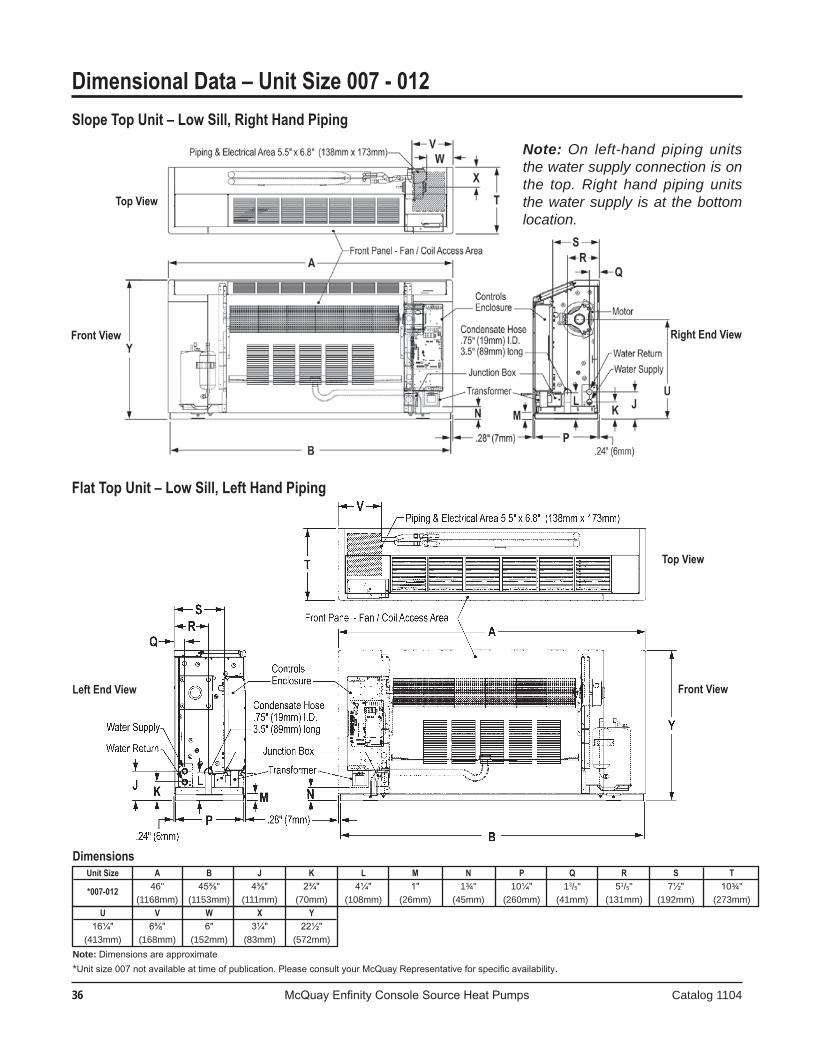
�� McQuay Enfinity Console Source Heat Pumps Catalog 1104
U V W X Y
16¼" 6⅝" 6" 3¼" 22½" (413mm) (168mm) (152mm) (83mm) (572mm)
Unit Size A B J K L M N P Q R S T
*007-012 46" 45⅜" 4⅜" 2¾" 4¼" 1" 1¾" 10¼" 13/5" 51/5" 7½" 10¾" (1168mm) (1153mm) (111mm) (70mm) (108mm) (26mm) (45mm) (260mm) (41mm) (131mm) (192mm) (273mm)
Dimensional Data – Unit Size 007 - 012
Dimensions
Note: Dimensions are approximate*Unit size 007 not available at time of publication. Please consult your McQuay Representative for specific availability.
Flat Top Unit – Low Sill, Left Hand Piping
Slope Top Unit – Low Sill, Right Hand Piping
Top View
Right End ViewFront View
Top View
Left End View Front View
Note: On left-hand piping units the water supply connection is on the top. Right hand piping units the water supply is at the bottom location.
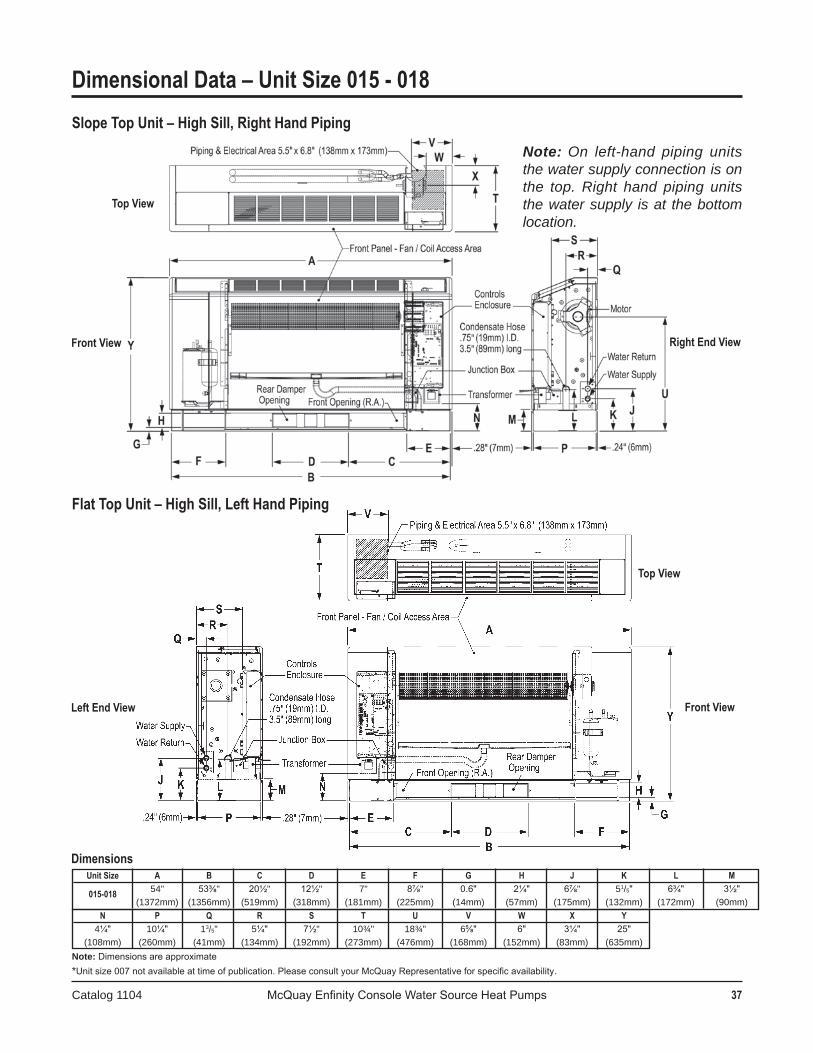
Catalog 1104 McQuay Enfinity Console Water Source Heat Pumps 37
N P Q R S T U V W X Y
4¼" 10¼" 13/5" 5¼" 7½" 10¾" 18¾" 6⅝" 6" 3¼" 25" (108mm) (260mm) (41mm) (134mm) (192mm) (273mm) (476mm) (168mm) (152mm) (83mm) (635mm)
Unit Size A B C D E F G H J K L M
015-018 54" 53⅜" 20½" 12½" 7" 8⅞" 0.6" 2¼" 6⅞" 51/5" 6¾" 3½" (1372mm) (1356mm) (519mm) (318mm) (181mm) (225mm) (14mm) (57mm) (175mm) (132mm) (172mm) (90mm)
Slope Top Unit – High Sill, Right Hand Piping
Dimensional Data – Unit Size 015 - 018
Dimensions
Note: Dimensions are approximate*Unit size 007 not available at time of publication. Please consult your McQuay Representative for specific availability.
Flat Top Unit – High Sill, Left Hand Piping
Top View
Right End ViewFront View
Top View
Left End View Front View
Note: On left-hand piping units the water supply connection is on the top. Right hand piping units the water supply is at the bottom location.
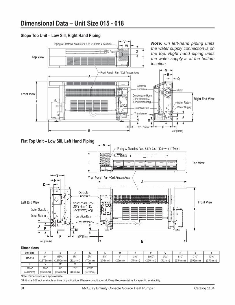
38 McQuay Enfinity Console Source Heat Pumps Catalog 1104
U V W X Y
16¼" 6⅝" 6" 3¼" 22½" (413mm) (168mm) (152mm) (83mm) (572mm)
Unit Size A B J K L M N P Q R S T
015-018 54" 53⅜" 4⅜" 2¾" 4¼" 1" 1¾" 10¼" 13/5" 5¼" 7½" 10¾" (1372mm) (1356mm) (111mm) (70mm) (108mm) (26mm) (45mm) (260mm) (41mm) (134mm) (192mm) (273mm)
Dimensional Data – Unit Size 015 - 018
Dimensions
Note: Dimensions are approximate*Unit size 007 not available at time of publication. Please consult your McQuay Representative for specific availability.
Slope Top Unit – Low Sill, Right Hand Piping
Top View
Right End View
Front View
Top View
Left End View Front View
Note: On left-hand piping units the water supply connection is on the top. Right hand piping units the water supply is at the bottom location.
Flat Top Unit – Low Sill, Left Hand Piping
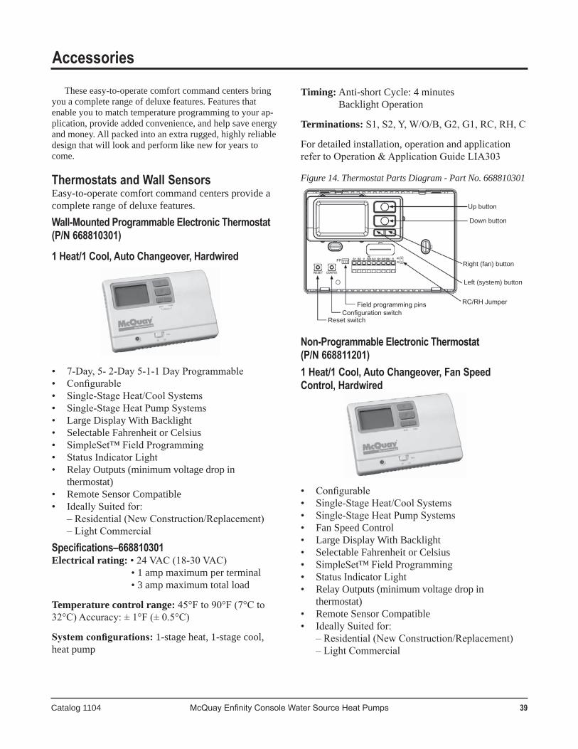
Catalog 1104 McQuay Enfinity Console Water Source Heat Pumps 39
Up button
Down button
Right (fan) button
Left (system) button
RC/RH JumperField programming pinsConfiguration switch
Reset switch
Timing:Anti-shortCycle:4minutes BacklightOperation
Terminations: S1, S2, Y, W/O/B, G2, G1, RC, RH, C
Fordetailedinstallation,operationandapplicationrefer to Operation & Application Guide LIA303
Figure 14. Thermostat Parts Diagram - Part No. 668810301
Non-Programmable Electronic Thermostat (P/N 668811201)1 Heat/1 Cool, Auto Changeover, Fan Speed Control, Hardwired
• Configurable• Single-Stage Heat/Cool Systems• Single-Stage Heat Pump Systems• FanSpeedControl• LargeDisplayWithBacklight• SelectableFahrenheitorCelsius• SimpleSet™ Field Programming• Status Indicator Light• RelayOutputs(minimumvoltagedropin
thermostat)• RemoteSensorCompatible• Ideally Suited for: – Residential (New Construction/Replacement) – Light Commercial
Accessories
Theseeasy-to-operatecomfortcommandcentersbringyouacompleterangeofdeluxefeatures.Featuresthatenableyoutomatchtemperatureprogrammingtoyourap-plication,provideaddedconvenience,andhelpsaveenergyandmoney.Allpackedintoanextrarugged,highlyreliabledesignthatwilllookandperformlikenewforyearstocome.
Thermostats and Wall SensorsEasy-to-operatecomfortcommandcentersprovideacompleterangeofdeluxefeatures.Wall-Mounted Programmable Electronic Thermostat (P/N 668810301)
1 Heat/1 Cool, Auto Changeover, Hardwired
• 7-Day, 5- 2-Day 5-1-1 Day Programmable• Configurable• Single-Stage Heat/Cool Systems• Single-Stage Heat Pump Systems• LargeDisplayWithBacklight• SelectableFahrenheitorCelsius• SimpleSet™ Field Programming• Status Indicator Light• RelayOutputs(minimumvoltagedropin
thermostat)• RemoteSensorCompatible• Ideally Suited for: – Residential (New Construction/Replacement) – Light CommercialSpecifications–668810301Electrical rating: • 24 VAC (18-30 VAC) •1ampmaximumperterminal •3ampmaximumtotalload
Temperature control range: 45°F to 90°F (7°C to 32°C) Accuracy: ± 1°F (± 0.5°C)
System configurations:1-stageheat,1-stagecool,heatpump
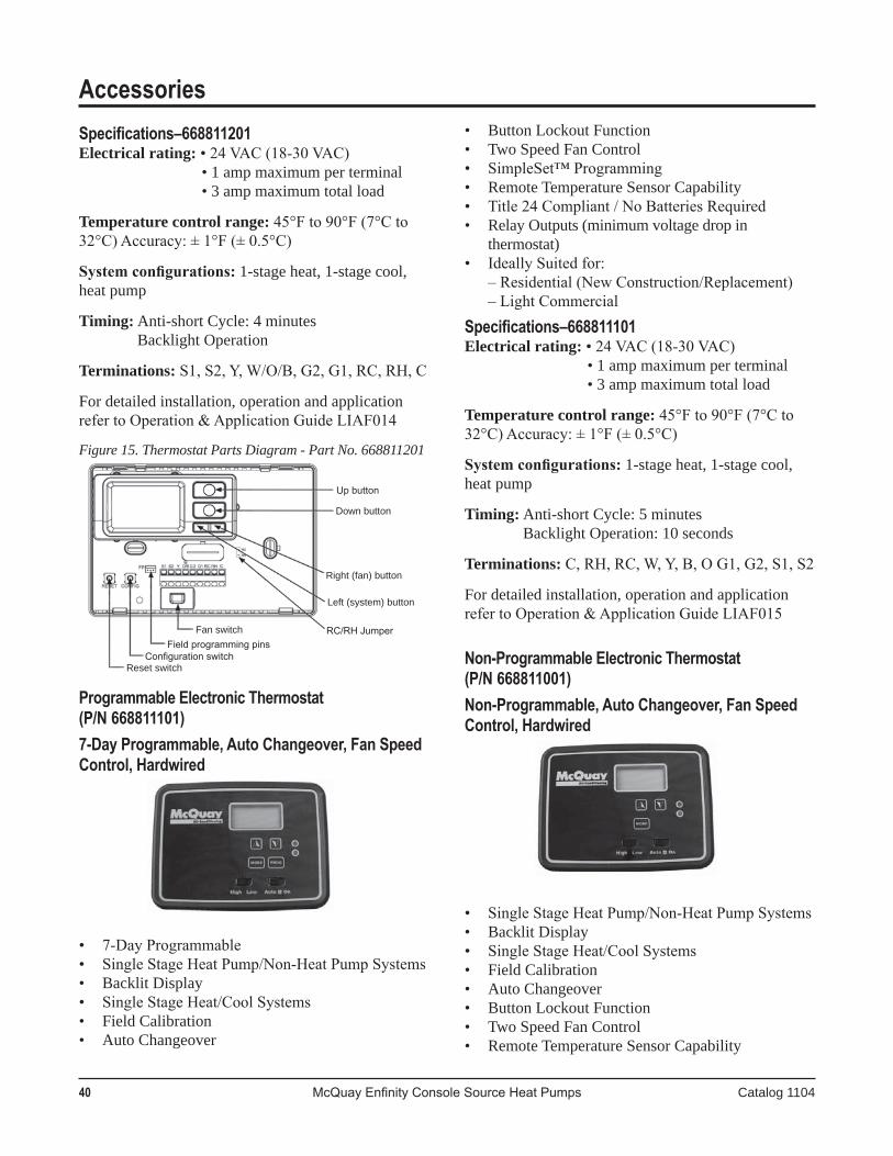
40 McQuay Enfinity Console Source Heat Pumps Catalog 1104
AccessoriesSpecifications–668811201Electrical rating: • 24 VAC (18-30 VAC) •1ampmaximumperterminal •3ampmaximumtotalload
Temperature control range: 45°F to 90°F (7°C to 32°C) Accuracy: ± 1°F (± 0.5°C)
System configurations:1-stageheat,1-stagecool,heatpump
Timing:Anti-shortCycle:4minutes BacklightOperation
Terminations: S1, S2, Y, W/O/B, G2, G1, RC, RH, C
Fordetailedinstallation,operationandapplicationrefer to Operation & Application Guide LIAF014
Figure 15. Thermostat Parts Diagram - Part No. 668811201
Programmable Electronic Thermostat (P/N 668811101)7-Day Programmable, Auto Changeover, Fan Speed Control, Hardwired
• 7-Day Programmable• Single Stage Heat Pump/Non-Heat Pump Systems• BacklitDisplay• Single Stage Heat/Cool Systems• FieldCalibration• AutoChangeover
Reset switch
Up button
Down button
Right (fan) button
Left (system) button
RC/RH JumperField programming pins
Configuration switch
Fan switch
Reset switch
• ButtonLockoutFunction• TwoSpeedFanControl• SimpleSet™ Programming• RemoteTemperatureSensorCapability• Title 24 Compliant / No Batteries Required• RelayOutputs(minimumvoltagedropin
thermostat)• Ideally Suited for: – Residential (New Construction/Replacement) – Light CommercialSpecifications–668811101Electrical rating: • 24 VAC (18-30 VAC) •1ampmaximumperterminal •3ampmaximumtotalload
Temperature control range: 45°F to 90°F (7°C to 32°C) Accuracy: ± 1°F (± 0.5°C)
System configurations:1-stageheat,1-stagecool,heatpump
Timing:Anti-shortCycle:5minutes BacklightOperation:10seconds
Terminations: C, RH, RC, W, Y, B, O G1, G2, S1, S2
Fordetailedinstallation,operationandapplicationrefer to Operation & Application Guide LIAF015
Non-Programmable Electronic Thermostat (P/N 668811001)Non-Programmable, Auto Changeover, Fan Speed Control, Hardwired
• Single Stage Heat Pump/Non-Heat Pump Systems• BacklitDisplay• Single Stage Heat/Cool Systems• FieldCalibration• AutoChangeover• ButtonLockoutFunction• TwoSpeedFanControl• RemoteTemperatureSensorCapability
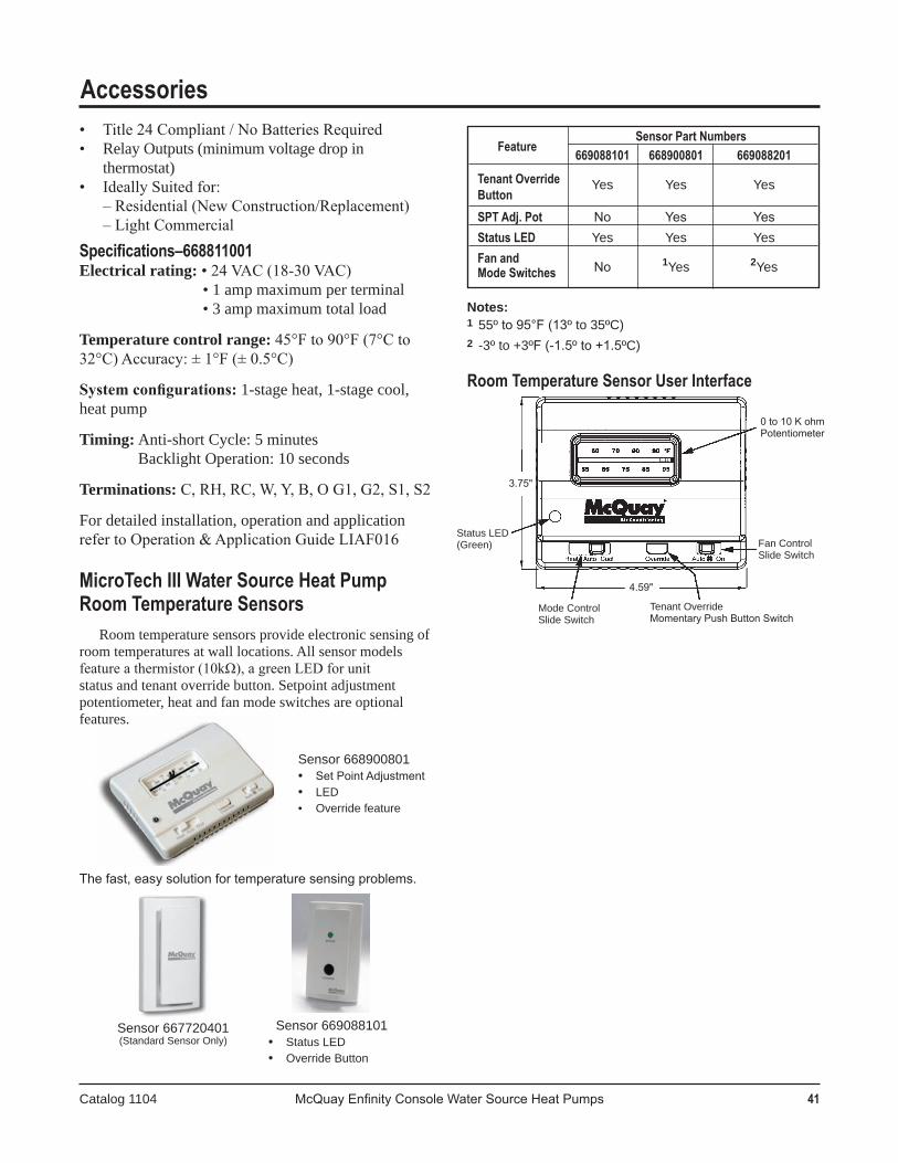
Catalog 1104 McQuay Enfinity Console Water Source Heat Pumps 41
Fan ControlSlide Switch
Mode ControlSlide Switch
Status LED(Green)
0 to 10 K ohmPotentiometer
Tenant OverrideMomentary Push Button Switch
4.59"
3.75"
• Title 24 Compliant / No Batteries Required• RelayOutputs(minimumvoltagedropin
thermostat)• Ideally Suited for: – Residential (New Construction/Replacement) – Light CommercialSpecifications–668811001Electrical rating: • 24 VAC (18-30 VAC) •1ampmaximumperterminal •3ampmaximumtotalload
Temperature control range: 45°F to 90°F (7°C to 32°C) Accuracy: ± 1°F (± 0.5°C)
System configurations:1-stageheat,1-stagecool,heatpump
Timing:Anti-shortCycle:5minutes BacklightOperation:10seconds
Terminations: C, RH, RC, W, Y, B, O G1, G2, S1, S2
Fordetailedinstallation,operationandapplicationrefer to Operation & Application Guide LIAF016
MicroTech III Water Source Heat Pump Room Temperature Sensors
Roomtemperaturesensorsprovideelectronicsensingofroomtemperaturesatwalllocations.Allsensormodelsfeature a thermistor (10kΩ), a green LED for unit statusandtenantoverridebutton.Setpointadjustmentpotentiometer,heatandfanmodeswitchesareoptionalfeatures.
The fast, easy solution for temperature sensing problems.
Accessories
Feature Sensor Part Numbers
669088101 668900801 669088201 Tenant Override Yes Yes Yes Button SPT Adj. Pot No Yes Yes
Status LED Yes Yes Yes
Fan and No
1Yes 2Yes
Mode Switches
Notes:1 55º to 95°F (13º to 35ºC)2 -3º to +3ºF (-1.5º to +1.5ºC)
Room Temperature Sensor User Interface
Sensor 669088101• Status LED• Override Button
Sensor 667720401(Standard Sensor Only)
Sensor 668900801• Set Point Adjustment• LED • Override feature
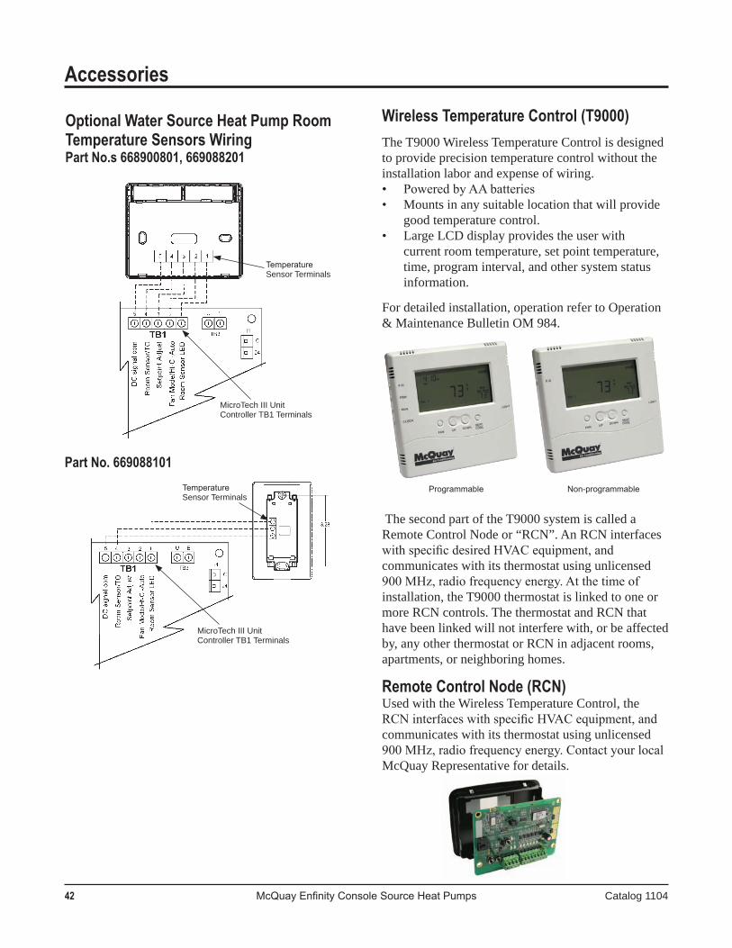
42 McQuay Enfinity Console Source Heat Pumps Catalog 1104
Accessories
Wireless Temperature Control (T9000)TheT9000WirelessTemperatureControlisdesignedtoprovideprecisiontemperaturecontrolwithouttheinstallationlaborandexpenseofwiring.• Powered by AA batteries• Mountsinanysuitablelocationthatwillprovide
goodtemperaturecontrol.• LargeLCDdisplayprovidestheuserwith
currentroomtemperature,setpointtemperature,time,programinterval,andothersystemstatusinformation.
Fordetailedinstallation,operationrefertoOperation&MaintenanceBulletinOM984.
ThesecondpartoftheT9000systemiscalledaRemoteControlNodeor“RCN”.AnRCNinterfaceswith specific desired HVAC equipment, and communicateswithitsthermostatusingunlicensed900 MHz, radio frequency energy. At the time of installation,theT9000thermostatislinkedtooneormoreRCNcontrols.ThethermostatandRCNthathavebeenlinkedwillnotinterferewith,orbeaffectedby,anyotherthermostatorRCNinadjacentrooms,apartments,orneighboringhomes.
Remote Control Node (RCN)UsedwiththeWirelessTemperatureControl,theRCN interfaces with specific HVAC equipment, and communicateswithitsthermostatusingunlicensed900 MHz, radio frequency energy. Contact your local McQuayRepresentativefordetails.
Programmable Non-programmable
Optional Water Source Heat Pump Room Temperature Sensors WiringPart No.s 668900801, 669088201
Temperature Sensor Terminals
MicroTech III Unit Controller TB1 Terminals
MicroTech III Unit Controller TB1 Terminals
Temperature Sensor Terminals
Part No. 669088101
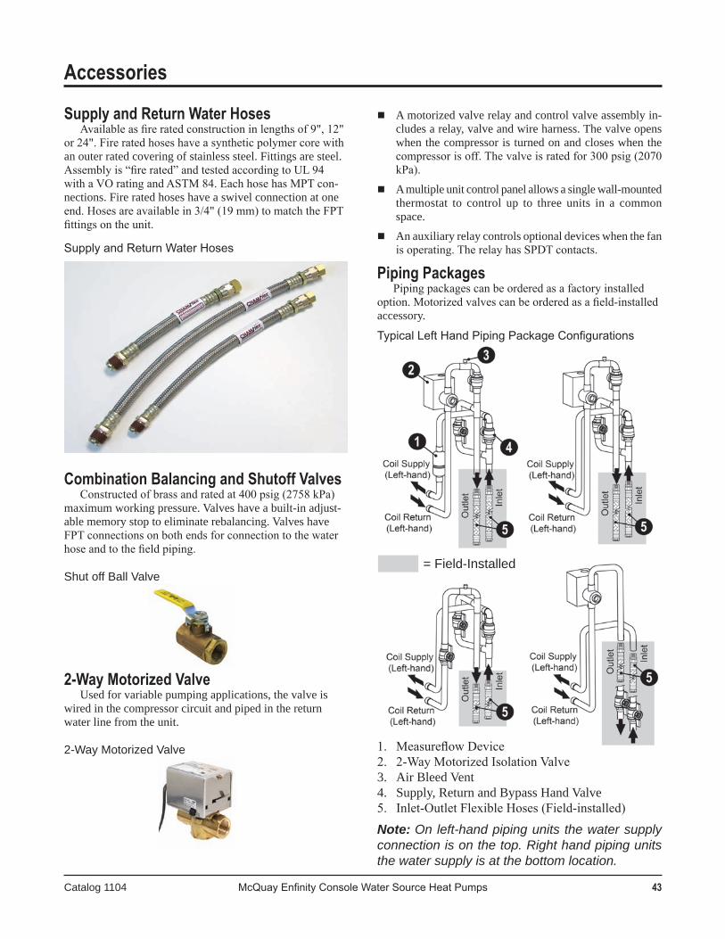
Catalog 1104 McQuay Enfinity Console Water Source Heat Pumps 43
Amotorizedvalverelayandcontrolvalveassemblyin-cludesarelay,valveandwireharness.Thevalveopenswhenthecompressoristurnedonandcloseswhenthecompressor is off. The valve is rated for 300 psig (2070 kPa).
Amultipleunitcontrolpanelallowsasinglewall-mountedthermostat to control up to three units in a commonspace.
Anauxiliaryrelaycontrolsoptionaldeviceswhenthefanis operating. The relay has SPDT contacts.
Piping PackagesPiping packages can be ordered as a factory installed
option. Motorized valves can be ordered as a field-installed accessory.
Typical Left Hand Piping Package Configurations
1. Measureflow Device2. 2-Way Motorized Isolation Valve3. AirBleedVent4. Supply,ReturnandBypassHandValve5. Inlet-Outlet Flexible Hoses (Field-installed)
Note:On left-hand piping units the water supply connection is on the top. Right hand piping units the water supply is at the bottom location.
Supply and Return Water Hoses Available as fire rated construction in lengths of 9", 12"
or 24". Fire rated hoses have a synthetic polymer core with anouterratedcoveringofstainlesssteel.Fittingsaresteel.Assembly is “fire rated” and tested according to UL 94 with a VO rating and ASTM 84. Each hose has MPT con-nections.Fireratedhoseshaveaswivelconnectionatoneend. Hoses are available in 3/4" (19 mm) to match the FPT fittings on the unit.
Supply and Return Water Hoses
Combination Balancing and Shutoff ValvesConstructed of brass and rated at 400 psig (2758 kPa)
maximumworkingpressure.Valveshaveabuilt-inadjust-ablememorystoptoeliminaterebalancing.ValveshaveFPT connections on both ends for connection to the water hose and to the field piping.
Shut off Ball Valve
2-Way Motorized ValveUsedforvariablepumpingapplications,thevalveis
wiredinthecompressorcircuitandpipedinthereturnwaterlinefromtheunit.
2-Way Motorized Valve
Accessories
= Field-Installed
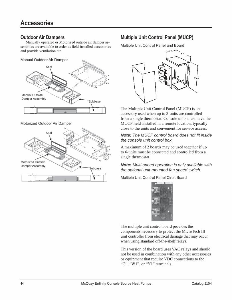
44 McQuay Enfinity Console Source Heat Pumps Catalog 1104
Accessories
Seal
Seal
Subbase
Subbase
Motorized Outside Damper Assembly
Manual Outside Damper Assembly
Outdoor Air DampersManuallyoperatedorMotorizedoutsideairdamperas-
semblies are available to order as field-installed accessories andprovideventilationair.
Manual Outdoor Air Damper
Motorized Outdoor Air Damper
Multiple Unit Control Panel (MUCP)Multiple Unit Control Panel and Board
The Multiple Unit Control Panel (MUCP) is an accessoryusedwhenupto3-unitsarecontrolledfromasinglethermostat.ConsoleunitsmusthavetheMUCP field-installed in a remote location, typically closetotheunitsandconvenientforserviceaccess.
Note: The MUCP control board does not fit inside the console unit control box.A maximum of 2 boards may be used together if up to 6-units must be connected and controlled from a singlethermostat.
Note: Multi-speed operation is only available with the optional unit-mounted fan speed switch.
Multiple Unit Control Panel Ciruit Board
Themultipleunitcontrolboardprovidesthecomponents necessary to protect the MicroTech III unitcontrollerfromelectricaldamagethatmayoccurwhenusingstandardoff-the-shelfrelays.
ThisversionoftheboardusesVACrelaysandshouldnotbeusedincombinationwithanyotheraccessoriesor equipment that require VDC connections to the “G”, “W1”, or “Y1” terminals.
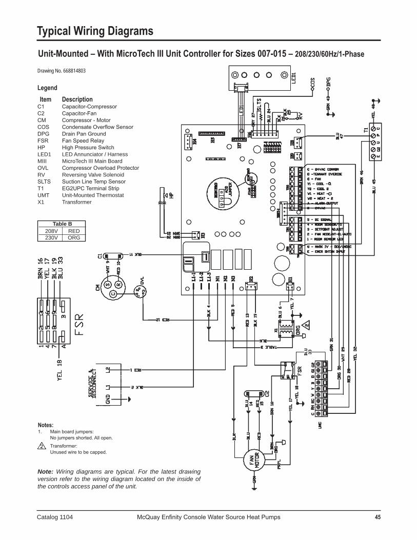
Catalog 1104 McQuay Enfinity Console Water Source Heat Pumps 45
Typical Wiring Diagrams
Unit-Mounted – With MicroTech III Unit Controller for Sizes 007-015 – 208/230/60Hz/1-Phase
Notes:1. Main board jumpers: No jumpers shorted. All open.
Transformer: Unused wire to be capped.
TableB 208V RED 230V ORG
Drawing No. 668814803
Note: Wiring diagrams are typical. For the latest drawing version refer to the wiring diagram located on the inside of the controls access panel of the unit.
Legend Item DescriptionC1 Capacitor-CompressorC2 Capacitor-FanCM Compressor - MotorCOS Condensate Overflow SensorDPG Drain Pan GroundFSR Fan Speed RelayHP High Pressure SwitchLED1 LED Annunciator / HarnessMIII MicroTech III Main BoardOVL Compressor Overload ProtectorRV Reversing Valve SolenoidSLTS Suction Line Temp SensorT1 EG2UPC Terminal StripUMT Unit-Mounted ThermostatX1 Transformer

46 McQuay Enfinity Console Water Source Heat Pumps Catalog 1104
Typical Wiring Diagrams
Notes:1. Main board jumpers: No jumpers shorted. All open.
2. I/O Expansion board jumpers: Jumper JP4 shorted.
Transformer: Unused wire to be capped.
TableB 208V RED 230V ORG
Drawing No. 668814811
Note: Wiring diagrams are typical. For the latest drawing version refer to the wiring diagram located on the inside of the controls access panel of the unit.
Legend Item DescriptionC1 Capacitor-CompressorC2 Capacitor-FanCC Compressor ContactorCM Compressor - MotorCOS Condensate Overflow SensorDPG Drain Pan GroundEWT Entering Water Temp SensorFHS Fan High Speed RelayFSR Fan Speed RelayHP High Pressure SwitchIOEXP I/O Expansion Board / HarnessLED1 LED Annunciator / HarnessLED2 LED Annunciator / HarnessSLTS Suction Line Temp SensorMIII MicroTech III Main BoardOVL Compressor Overload ProtectorR2 Relay - Electric HeatRV Reversing Valve SolenoidT1 EG2UCP Terminal StripTB1 Terminal BlockX1 Transformer
Unit-Mounted – With MicroTech III Unit Controller With Electric Heat for Size 018208/230/60Hz/1-Phase
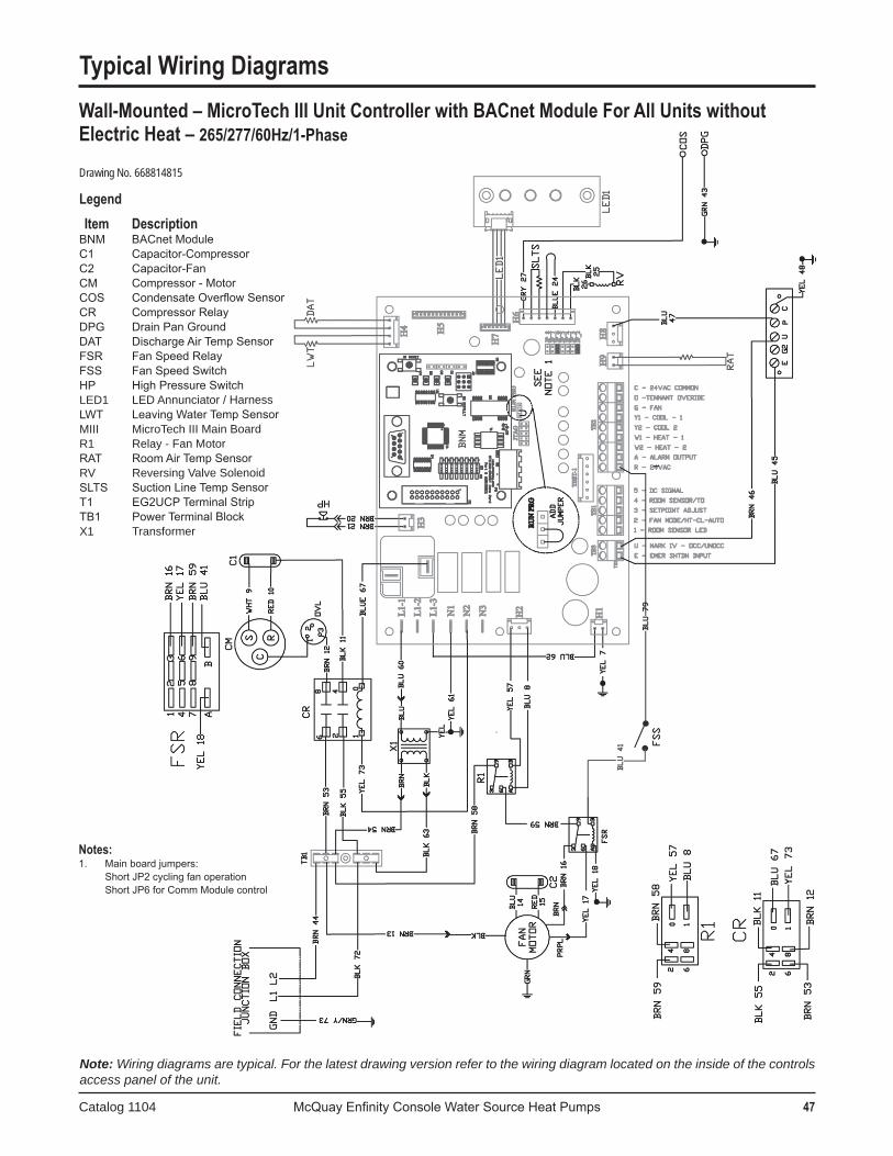
Catalog 1104 McQuay Enfinity Console Water Source Heat Pumps 47
Typical Wiring Diagrams
Notes:1. Main board jumpers: Short JP2 cycling fan operation Short JP6 for Comm Module control
Drawing No. 668814815
Legend Item DescriptionBNM BACnet ModuleC1 Capacitor-CompressorC2 Capacitor-FanCM Compressor - MotorCOS Condensate Overflow SensorCR Compressor RelayDPG Drain Pan GroundDAT Discharge Air Temp SensorFSR Fan Speed RelayFSS Fan Speed SwitchHP High Pressure SwitchLED1 LED Annunciator / HarnessLWT Leaving Water Temp SensorMIII MicroTech III Main BoardR1 Relay - Fan MotorRAT Room Air Temp SensorRV Reversing Valve SolenoidSLTS Suction Line Temp SensorT1 EG2UCP Terminal StripTB1 Power Terminal BlockX1 Transformer
Wall-Mounted – MicroTech III Unit Controller with BACnet Module For All Units without Electric Heat – 265/277/60Hz/1-Phase
Note: Wiring diagrams are typical. For the latest drawing version refer to the wiring diagram located on the inside of the controls access panel of the unit.

48 McQuay Enfinity Console Source Heat Pumps Catalog 1104
Engineering Guide Specifications General
Contractor shall furnish and install Water Source Heat Pump units as indicated on plans. Each unit shall be listed in the ARI directory of certified products, ISO rated and CETL or CE listed. Each unit shall be fully run tested at the factory. Each unit shall ship in its own corrugated box. The unit shall consist of a subbase for floor mounting, a cabinet front, a left and right end corner panel and a slide-out chassis for attachment to the back wall and floor mounting on the subbase. The chassis shall include the refrigerationsystem,fanassemblyandallcontrols.
Theunitshallbecapableofbeingshippedasa(chooseone):□ completeunitincludingsubbase,cabinetfront,leftandrightendcornerpanelsandchassis.□ chassisonlyforspareunitorfutureinstallation.
Cabinet and ChassisThe cabinet shall be fabricated from 18 or 20-gauge steel and include multiple holes/slots for attachment to the wall and
floor. The cabinet sections shall be finished in Antique Ivory or Cupola White baked enamel. The subbase shall be finished in OxfordBrownortomatchthecabinetcolor.Thecabinetshallbeinsulated.Thechassisshallhousetherefrigerationsystem,water piping, fan assembly and all controls. Panels shall provide access to the fan compartment and the compressor/control box compartment. The filter shall be a 1/2" (25mm) throwaway type with front removal from the subbase.
Thechassisshallbefullyinsulatedandincorporateanon-corrosivecondensatepan.Thedrainhoseshallhaveaformedcondensatetrap.
The cabinet shall be 10¾" (273mm) maximum depth and shall (choose one):□ have a 22° slope top angle and an opening in the subbase for return air with a maximum height of 25" (635mm).□ have a flat top and an opening in the subbase for return air with a maximum height of 25" (635mm).
(Chooseone:)□ The slope top cabinet shall incorporate adjustable discharge grilles and thermostat cover with flush mounting to the front
and sides of the cabinet. The discharge grille shall direct the air at an 11° angle from the vertical and be field reversible for a 33° discharge angle. The grille shall be constructed of fire retardant ABS polycarbonate. The left and right cabinet access end corner panels shall be Antique Ivory or Cupola White and be constructed of polycarbonate to match the dischargegrillesandcontroldoor.
The flat top unit shall (choose one):□ incorporateaone-piecestamped,paintedsteelgrille.ThegrilleshallbepaintedOxfordBrownormatchthecabinet
color.□ incorporate no cabinet and a duct collar on the chassis for installation into a field supplied custom cabinet enclosure.
Refrigerant CircuitEach unit shall have a sealed refrigerant circuit including a compressor, capillary expansion tube(s), finned tube heat exchanger,
reversingvalve,water-to-refrigerantcoaxialheatexchanger,highandlowsideaccessvalves,andsafetycontrols.Compressor shall be rotary type with external vibration mounts and thermal overload protection. The finned tube coil shall
be constructed of aluminum fins bonded to copper tubes. The coaxial heat exchanger shall be constructed of a copper inner tube and a steel outer tube and be U.L. listed. The heat exchanger shall be rated for 400 psig (2759 kPa) on the water side and 450 psig (3104 kPa) on the refrigerant side.
Safetycontrolsshallincludealowsuctiontemperature(freezestat)switchandahighrefrigerantpressureswitchtolockoutcompressoroperation.Unitshallbecapableofbeingresetonlybyinterruptingthepowersupplytotheunit.Manualresetofthesafetyswitchattheunitshallnotbeallowed.Unitshallbecapableofstartingatenteringairof40°F(5°C)andenteringwaterat 70°F (21°C) with both air and water flow rates at the ARI rating conditions.
ElectricalAcontrolboxwithremovabletopcovershallbelocatedontherightorleftsideofthechassisandshallcontaincontrolsfor
compressor, reversing valve and fan motor operation and a 50 VA transformer. The chassis shall have a 2" x 4" (51mm x mm) junctionboxmountedonthesidetofacilitatemainpowerwiringandbecapableofbeinglocatedontheleftorrightsideofthechassis.UnitshallbenameplatedtoaccepttimedelayfusesorHACRcircuitbreakerforbranchovercurrentprotectionofthepowersource.

Catalog 1104 McQuay Enfinity Console Water Source Heat Pumps 49
Engineering Guide SpecificationsFan and Motor Assembly
Unitshallhaveadirect-drivetangentialfanwheel.Thefanhousingshallbeinsulatedwithclosed-cellinsulationtohelpattenuate noise. The motor shall be thermally protected, two-speed, PSC type and be connected to the chassis. The motor shall haveaplugconnectionandbeconnectedtothechassiswiththreescrewsforeasyremovalandservice.
PipingThe supply and return lines shall be 5/8" O.D. copper tubing and terminate away from the side of the chassis. The internally
trapped condensate shall be a 3/4" (19mm) I.D. clear flexible vinyl tube protruding 14" (356mm) out of the chassis for connection at the floor or at the back wall. The supply, return and condensate tubing shall be capable of terminating at the left or right side ofthechassis.
Thermostat / Space Sensor OptionsThethermostatshallbe(chooseone):□ unit-mounted non-programmable w/LCD display. □ wall-mountedsensor.□ unit-mounted 7-day programmable w/LCD display. □ wall-mounted sensor w/status LED and night setback□ wall-mounted non-programmable w/LCD display. override.□ wall-mounted 7-day programmable w/LCD display. □ wall-mounted sensor w/setpoint adjustment □ wirelessnon-programmable. (55°Fto95°F).□ wireless 7-day programmable. □ wall-mounted sensor w/setpoint adjustment (-3°Fto+3°F).
MicroTech III Unit ControllerUnitshallhaveamicroprocessorbasedcontrolsystemandproviderandomstart,compressorshortcycleprotection,grounded
signalinput(oneeach)foractivationofunoccupiedoremergencyshutdownmodes,LEDfaultstatus,optimaltwo-houroverrideof the unoccupied mode, brownout protection, condensate overflow protection, remote reset of automatic lockouts, fault retry tominimizenuisancetrips,defrostcycleandpumprestartrelayoutput.
Thecontrolsystemtypeshallhaveanoptionof,(chooseone):□ unit-mounted non-programmable w/LCD display, Hi-Lo-auto fan speed control.□ unit-mounted 7-day programmable w/LCD display, Hi-Lo-auto fan speed control.□ wall-mounted non-programmable w/LCD display, Hi-Lo-auto fan speed control.□ wall-mounted 7-day programmable w/LCD display, Hi-Lo-auto fan speed control.□ wall-mounted space temperature sensor/setpoint adjustment (55° F to 95°F), auto- On fan speed control.□ wall-mounted space temperature sensor/setpoint adjustment (-3° F to +3°F), auto- On fan speed control.□ wall-mountedsensor,nosetpointadjustment.□ wall-mountedsensor,nightsetbackoverridebuttonandLEDstatuslight.□ wirelessthermostatandreceiver,non-programmable,Hi-Lo-autofanspeedcontrol.□ wireless thermostat and receiver, 7-day programmable, Hi-Lo-auto fan speed control.
Optional Boilerless System Electric HeatUnitshallhaveafactorymountedelectricheaterandcontrolsystem.Aunit-mountedenteringwatertemperaturethermostat
shalllockoutcompressorheatingoperationat58°F(15°C).Onacallforheating,theelectricheatershallbeactivated.Whentheenteringwatertemperaturerises,theunitshallresumenormalcompressorheatingoperation.Anemergencyheatswitchshallprovideheatingonlyfromtheelectricheaterintheeventofacompressorfailure.
Optional Outside Air Damper KitThedamperislocatedinthebackofthesubbaseforoutsideairintakeandshallbeoperatedmanuallyfromthesubbase.
Damper can be configured for manual adjustment or motorized control.
50 McQuay Enfinity Console Source Heat Pumps Catalog 1104
Engineering Guide SpecificationsOptional Plug Cord Kit
The chassis shall incorporate a plug cord for connection to a unit-mounted receptacle/fused disconnect switch box in the subbaseunderthechassis.Theplugcordshallelectricallymatetothereceptacle.
Optional Receptacle/Fused Disconnect KitThepermanentportionofthecabinetshallhaveareceptacleandfuseddisconnectswitchtofacilitatemainpowerelectrical
connectionpermittingchassisremovalwithoutdisconnectingmainpowerwiring.
Optional Motorized Valve PackageThereturnwaterlineshallhaveamotorizedwatervalve.Thevalveshalloperateinconjunctionwithcompressoroperation;
valve opens before compressor is turned on. The valve shall have a maximum rating of 150 psig (1035 kPa).
Field-Installed Accessories
Optional Flexible HosesEach unit can be supplied with two steel fire-rated hoses for connection to unit and field piping. Hose assembly shall be
rated at 500 psig (3494 kPa).
Optional Ball ValvesEachunitcanbesuppliedwithtwocombinationbalancingandshutoffvalveswithadjustablememorystop.
Optional Filter Kits12-pk. filter kits available from selection software.

McQuay Water Source Heat PumpsQuality Products, Flexible Configurations
©2009 McQuay International (800) 432-1342 www.mcquay.com Catalog 1104 (4/09)
Large Vertical Units 6 to 25 Ton
Enfinity Vertical & Horizontal Units 1/2 to 6 Ton
Console Units 1/2 to 11/2 Ton
Rooftop Units 3 to 35 Ton
Water to Water Source Heat Pump Units 3 to 35 Ton
Large Horizontal Units 6 to 10 Ton
Warranty
All McQuay equipment is sold pursuant to its standard terms and conditions of sale, including Limited Product Warranty. Consult your local McQuay Representative for warranty details. Refer to Form 933-43285Y. To find your local McQuay Representative, go to www.mcquay.com.
This document contains the most current product information as of this printing. For the most up-to-date product information, please go to www.mcquay.com.
Products Manufactured in an ISO Certified Facility.