ENERGYMID EM - gossenmetrawatt.com · BC Selected baud rate of 4800 bps BD Selected baud rate of...
54
Interface Description ENERGYMID|EM M-Bus Interface of Energy Meters U228X-W2, U238X-W2 3-349-909-03 3/5.18
Transcript of ENERGYMID EM - gossenmetrawatt.com · BC Selected baud rate of 4800 bps BD Selected baud rate of...

Interface Description
ENERGYMID|EM M-Bus Interface of Energy Meters U228X-W2, U238X-W2
3-349-909-03 3/5.18

2 GMC-I Messtechnik GmbH
Table of Contents
1 Overview ......................................................................................................................................................... 3
2 Telegram Formats .......................................................................................................................................... 3 2.1 Telegram Fields ........................................................................................................................................... 3 2.1.1 C Field .......................................................................................................................................................... 3 2.1.2 A Field .......................................................................................................................................................... 4 2.1.3 CI Field ......................................................................................................................................................... 4 2.1.4 L Field .......................................................................................................................................................... 4 2.1.5 CS Field ....................................................................................................................................................... 5 2.2 User Data (long telegram) ............................................................................................................................ 5 2.2.1 Coding of User Data from the Slave to the Master: Beginning of the Telegrams ......................................... 5 2.2.2 Coding of User Data from the Slave to the Master: Data Records ............................................................... 5
3 Communications Process ............................................................................................................................. 9 3.1 Transmission/Acknowledgement Procedure ................................................................................................ 9 3.1.1 SND_NKE .................................................................................................................................................... 9 3.1.2 SND_UD .................................................................................................................................................... 10 3.1.3 REQ_UD2 .................................................................................................................................................. 35 3.1.4 RSP_UD .................................................................................................................................................... 35
4 Appendix ....................................................................................................................................................... 44 4.1 Communication Procedure ......................................................................................................................... 44 4.2 Parameter Set List − All Retrievable Values .............................................................................................. 45 4.3. Standard Telegram .................................................................................................................................... 48
5 Application Notes ......................................................................................................................................... 49 5.1 Operating Logbook and Load Profile (feature Z1) ...................................................................................... 49 5.2 Cutoff Date Meter ....................................................................................................................................... 49 5.3 Resettable Meter ........................................................................................................................................ 49 5.4. Set Telegram ............................................................................................................................................. 50 5.5. ENERGYMID Tool ..................................................................................................................................... 51
6 Control and Display Functions ................................................................................................................... 53
7 Product Support ........................................................................................................................................... 54

GMC-I Messtechnik GmbH 3
1 Overview • M-Bus interface per EN13757-2 and EN13757-3 • Wired with 2-wire twisted-pair cable • 2 screw terminals for M-Bus connection • M-Bus interface current consumption: ≤ 1,5 mA. This corresponds to 1 standard load. • Selectable data transmission rates: 300, 600, 1200, 2400, 4800 or 9600 baud • The standard baud rate is 2400 baud. • The standard primary address is 0.
2 Telegram Formats There are 3 telegram formats, each of which has a different first byte: • Single character: This telegram consists of the E5h character only and serves the purpose of receipt acknowledgement. • Short telegram: This telegram is distinguished by its start character, namely 10h, and always includes 5 characters. It’s used by the M-Bus master to request data from the M-Bus slave. • Long telegram: This telegram begins with start character 68h. It consists of a variable number of bytes and also includes data. It’s used by the M-Bus master in order to transmit commands to the M-Bus slave, and by the M-Bus slave to transmit requested data to the M-Bus master.
Byte Single Character Short Telegram Long Telegram
1 E5 10 68
2 C field L field 3 A field L field (repetition) 4 CS (checksum) 68 5 16 C field 6 A field 7 CI field 8 ... YY Data (0 ... 246 bytes) YY + 1 CS (checksum) YY + 2 16
Table 2.1: M-Bus Telegram Formats (all bytes in hexadecimal format).
2.1 Telegram Fields Telegram fields C, A, CI, L and CS have a length of 1 byte (8 bits) and execute predefined tasks for M-Bus communication.
2.1.1 C Field The control field contains information about the direction of communication, success of the current transmission and the function of the telegram.
Bit Number 7 6 5 4 3 2 1 0
Master > slave 0 1 FCB FCV F3 F2 F1 F0 Slave > master 0 0 ACD DFC F3 F2 F1 F0
Table 2.1.1a: C Field Bit Sequence Bit no. 6 indicates the direction of communication. It’s set to 1 in the master to slave direction, and otherwise to 0. When the master sets bit 4 (FCV = frame count bit valid) to 1 the slave must observe bit 5 (FCB = frame count bit), and the slave should otherwise ignore the FCB. The FCB indicates that successful transmission has taken place. The master switches the bit after receiving a successful response from a slave. In the case of a multiple telegram, the slave must then send the next telegram of the response. If the expected response is not transmitted or if receipt of the response fails, the master sends the same telegram with unchanged FCB once again.
4 GMC-I Messtechnik GmbH
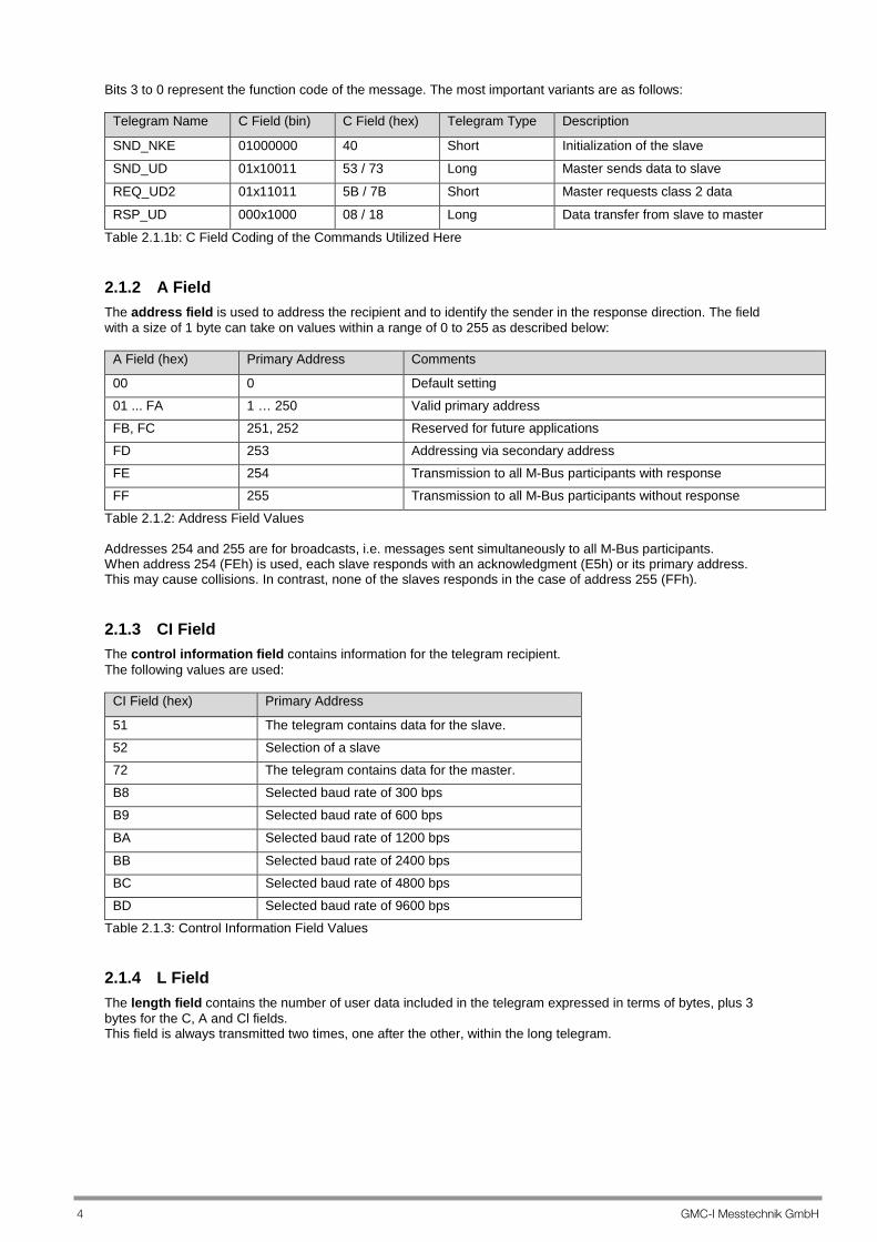
Bits 3 to 0 represent the function code of the message. The most important variants are as follows:
Telegram Name C Field (bin) C Field (hex) Telegram Type Description
SND_NKE 01000000 40 Short Initialization of the slave
SND_UD 01x10011 53 / 73 Long Master sends data to slave
REQ_UD2 01x11011 5B / 7B Short Master requests class 2 data
RSP_UD 000x1000 08 / 18 Long Data transfer from slave to master
Table 2.1.1b: C Field Coding of the Commands Utilized Here
2.1.2 A Field The address field is used to address the recipient and to identify the sender in the response direction. The field with a size of 1 byte can take on values within a range of 0 to 255 as described below:
A Field (hex) Primary Address Comments
00 0 Default setting 01 ... FA 1 … 250 Valid primary address FB, FC 251, 252 Reserved for future applications FD 253 Addressing via secondary address FE 254 Transmission to all M-Bus participants with response FF 255 Transmission to all M-Bus participants without response
Table 2.1.2: Address Field Values Addresses 254 and 255 are for broadcasts, i.e. messages sent simultaneously to all M-Bus participants. When address 254 (FEh) is used, each slave responds with an acknowledgment (E5h) or its primary address. This may cause collisions. In contrast, none of the slaves responds in the case of address 255 (FFh).
2.1.3 CI Field The control information field contains information for the telegram recipient. The following values are used:
CI Field (hex) Primary Address
51 The telegram contains data for the slave. 52 Selection of a slave 72 The telegram contains data for the master. B8 Selected baud rate of 300 bps B9 Selected baud rate of 600 bps
BA Selected baud rate of 1200 bps
BB Selected baud rate of 2400 bps BC Selected baud rate of 4800 bps BD Selected baud rate of 9600 bps
Table 2.1.3: Control Information Field Values
2.1.4 L Field The length field contains the number of user data included in the telegram expressed in terms of bytes, plus 3 bytes for the C, A and Cl fields. This field is always transmitted two times, one after the other, within the long telegram.
GMC-I Messtechnik GmbH 5
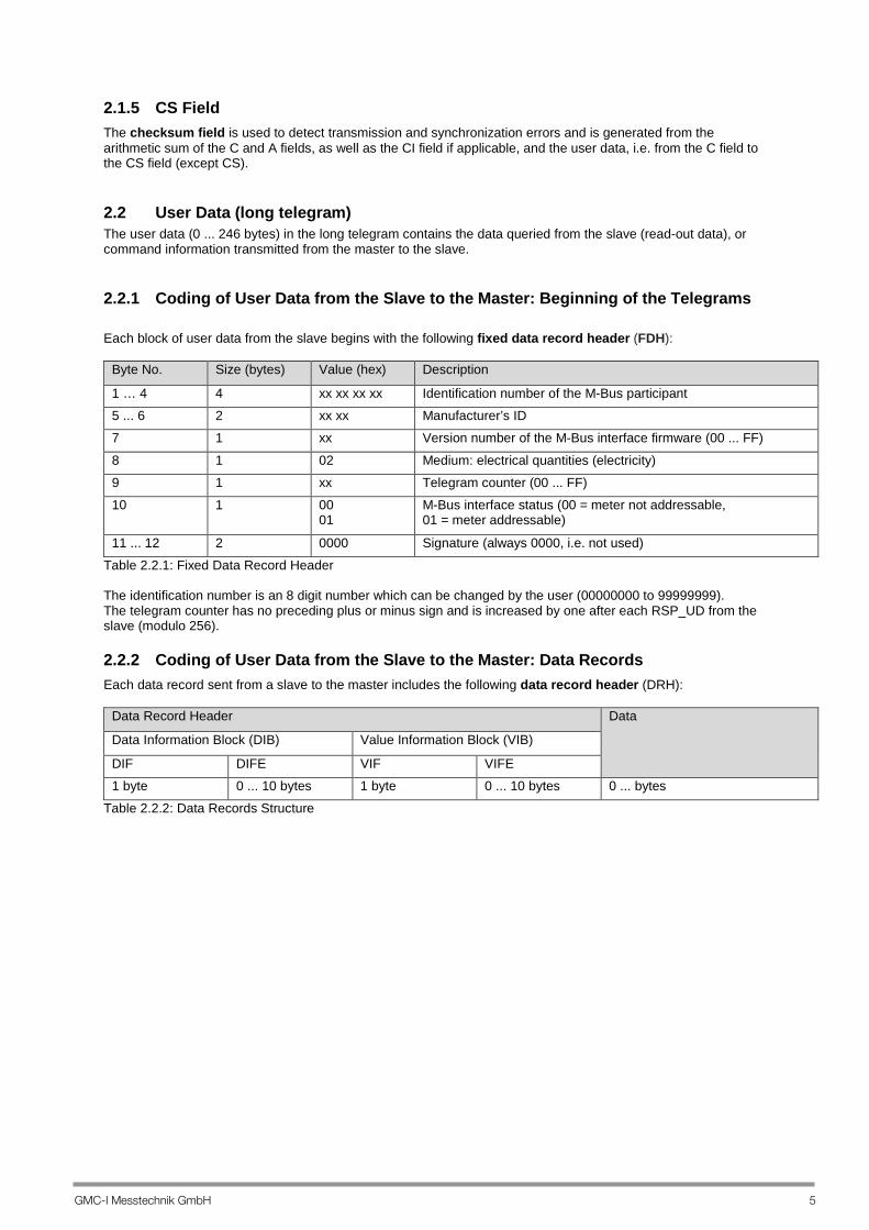
2.1.5 CS Field The checksum field is used to detect transmission and synchronization errors and is generated from the arithmetic sum of the C and A fields, as well as the CI field if applicable, and the user data, i.e. from the C field to the CS field (except CS).
2.2 User Data (long telegram) The user data (0 ... 246 bytes) in the long telegram contains the data queried from the slave (read-out data), or command information transmitted from the master to the slave.
2.2.1 Coding of User Data from the Slave to the Master: Beginning of the Telegrams Each block of user data from the slave begins with the following fixed data record header (FDH):
Byte No. Size (bytes) Value (hex) Description
1 … 4 4 xx xx xx xx Identification number of the M-Bus participant 5 ... 6 2 xx xx Manufacturer’s ID 7 1 xx Version number of the M-Bus interface firmware (00 ... FF)
8 1 02 Medium: electrical quantities (electricity) 9 1 xx Telegram counter (00 ... FF) 10 1 00
01 M-Bus interface status (00 = meter not addressable, 01 = meter addressable)
11 ... 12 2 0000 Signature (always 0000, i.e. not used) Table 2.2.1: Fixed Data Record Header The identification number is an 8 digit number which can be changed by the user (00000000 to 99999999). The telegram counter has no preceding plus or minus sign and is increased by one after each RSP_UD from the slave (modulo 256).
2.2.2 Coding of User Data from the Slave to the Master: Data Records Each data record sent from a slave to the master includes the following data record header (DRH):
Data Record Header Data
Data Information Block (DIB) Value Information Block (VIB)
DIF DIFE VIF VIFE 1 byte 0 ... 10 bytes 1 byte 0 ... 10 bytes 0 ... bytes
Table 2.2.2: Data Records Structure

6 GMC-I Messtechnik GmbH
2.2.2.1 Data Information Block (DIB) The data information block (DIB) includes at least one data information field (DIF). This DIF byte can be expanded with a data information field extension (DIFE) of up to 10 bytes. DIF coding for this protocol:
Bit Name Description
7 Extension bit Indicates whether or not a DIFE byte follows: 0 = no 1 = yes
6 LSB of the memory location number Always 0, i.e. not used 5 … 4 Function field Specifies the type of value, always:
00 = momentary value
3 ... 0 Data field Length and coding of the data: 0001: 8-bit integer 0010: 16-bit integer 0011: 24-bit integer 0100: 32-bit integer 0110: 48-bit integer 0111: 64-bit integer 1100: 8-digit BCD 1101: variable length
Table 2.2.2.1: Data Information Field Structure (DIF) Coding of the first DIFE for power and energy:
Bit Name Description
7 Extension bit Indicates whether or not a further DIFE byte follows: 1 = yes
6 Unit Specifies the type of energy or power: 0 = active 1 = reactive
5 … 4 Tariff Specifies the tariff to which the values belong: Bit 5 … tariff bit 1 Bit 4 … tariff bit 0
3 ... 0 Memory location number Always 0000
Table 2.2.2.1a Coding of the second DIFE for power and energy:
Bit Name Description
7 Extension bit Indicates whether or not a further DIFE byte follows: 0 = no (for power) 1 = yes (for energy)
6 Unit Specifies the source of energy or power: 0 = primary 1 = secondary
5 ... 4 Tariff Specifies the tariff to which the values belong: Bit 5 … tariff bit 3 Bit 4 … tariff bit 2
3 … 0 Memory location number Always 0000 Table 2.2.2.1b

GMC-I Messtechnik GmbH 7
Coding of the third DIFE for power and energy:
Bit Name Description
7 Extension bit Indicates whether or not a DIFE byte follows: 0 = no
6 Unit Specifies the type of energy: 0 = imported 1 = exported
5 ... 4 Tariff Bit 5 … always 0 Bit 4 … always 0
3 … 0 Memory location number Always 0000 Table 2.2.2.1c 2.2.2.2 Value Information Block The value information block (VIB) includes at least one value information field (VIF). This byte can be expanded with a value information field extension (VIFE) of up to 10 values. VIF coding:
Bit Name Description
7 Extension bit Indicates whether or not a VIFE byte follows: 0 = no 1 = yes
6 ... 0 Value information Includes information about the individual value such as unit, multiplier etc.
Table 2.2.2.2a: Value Information Field Structure (VIF) VIFE coding:
Bit Name Description
7 Extension bit Indicates whether or not a further VIFE byte follows: 0 = no 1 = yes
6 ... 0 Value information Includes information about the individual value such as unit, multiplier etc.
Table 2.2.2.2a: Value Information Field Extension Structure (VIFE) 2.2.2.3 Standard Value Information Field (VIF)
VIFE (bin) VIFE (hex) Description Unit
00100010 22 Total operating hours h 01111001 79 Setting of the secondary address None
01111010 7A Setting of the primary address None 10000010 8x Energy See section 3.1.4.9 10101000 A8 Power W 11111101 FD A standard VIFE from table extension follows None 11111111 FF Further manufacturer-specific VIFE follows None
Table 2.2.2.3: Standard Value Information Field

8 GMC-I Messtechnik GmbH
2.2.2.4 Standard Value Information Field Extension (VIFE)
VIF (bin) VIF (hex) Description Unit
00001011 0B Parameter mask identification None 00001100 0C Firmware version None 00001101 0D Hardware version None 11001100 CC Voltage V 11011001 D9 Current A
Table 2.2.2.4: Standard Value Information Field Extension 2.2.2.5 Manufacturer-Specific VIFE
VIFE (hex) Description
00 Mean value of the phases 01 Phase 1 02 Phase 2 03 Phase 3 04 Neutral 05 Phase 1 to phase 2 06 Phase 2 to phase 3 07 Phase 3 to phase 1 08 Mean value, phase-to-phase
09 Total 0A Resettable 0B Cutoff date function 10 THD voltage (steps of 0.001) 11 THD current (steps of 0.001) 12 Frequency (unit: mHz) 13 Power factor (steps of 0.001) 14 Momentary tariff 15 Current transformer ratio (CT) 16 Voltage transformer ratio (VT) 17 Read operating logbook data
18 Read load profile data 19 Specified date point for next reset 1A Load profile integrating period 1B Meter features 1C Next specified cutoff date 1D Date on which resettable meter readings were last reset
1E Last cutoff date 20 Operating hours since last reset 21 Clear data memory 22 Version 23 Define tariff
Table 2.2.2.5: Manufacturer-Specific Information Field Extensions If bit 7 in the specific value information field extension (VIFE) is set to 1, a further VIFE byte follows. If bit 7 is set to 0, the first data byte follows directly.

GMC-I Messtechnik GmbH 9
3 Communications Process The M-Bus interface accepts two types of transmission: Send / confirm > SND / CON Request / respond > REQ / RSP
Standard communication between M-Bus master and M-Bus slave is as follows: Master Slave SND_NKE > E5h SND_UD > E5h REQ_UD2 > RSP_UD
3.1 Transmission/Acknowledgement Procedure
3.1.1 SND_NKE The procedure is used for starting after an interruption or after beginning communication. If the slave has been selected for secondary addressing, it’s unselected. The value of the frame count bit (FCB) in the slave is reset, i.e. it’s expected that the first telegram from a master with (FCV = 1) includes (FCB = 1). The slave acknowledges correct receipt of a telegram with the single character acknowledgement (E5h), or doesn’t respond if the telegram has not been correctly received. Structure of the SND_NKE command:
Byte No. Size (bytes) Value (hex) Description
1 1 10 Start character – short telegram 2 1 40 C field 3 1 Xx A field – primary address
00 ... FA: valid primary address FB, FC: reserved for future applications FD: addressing via secondary address FE: transmission to all M-Bus slaves (each slave responds with E5h) FE: transmission to all M-Bus slaves (no slaves respond)
4 1 Xx CS (checksum), calculated from bytes 2 and 3 5 1 16 End-of-message character
Table 3.1.1: SND_NKE Command Structure Response from the slave: E5h
10 GMC-I Messtechnik GmbH
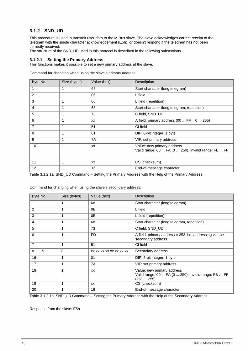
3.1.2 SND_UD This procedure is used to transmit user data to the M-Bus slave. The slave acknowledges correct receipt of the telegram with the single character acknowledgement (E5h), or doesn’t respond if the telegram has not been correctly received. The structure of the SND_UD used in this protocol is described in the following subsections. 3.1.2.1 Setting the Primary Address This functions makes it possible to set a new primary address at the slave. Command for changing when using the slave’s primary address:
Byte No. Size (bytes) Value (hex) Description
1 1 68 Start character (long telegram) 2 1 06 L field 3 1 06 L field (repetition) 4 1 68 Start character (long telegram, repetition) 5 1 73 C field, SND_UD 6 1 xx A field, primary address (00 ... FF = 0 ... 255) 7 1 51 CI field
8 1 01 DIF: 8-bit integer, 1 byte 9 1 7A VIF: set primary address 10 1 xx Value: new primary address
Valid range: 00 ... FA (0 … 250), invalid range: FB ... FF
11 1 xx CS (checksum) 12 1 16 End-of-message character
Table 3.1.2.1a: SND_UD Command – Setting the Primary Address with the Help of the Primary Address Command for changing when using the slave’s secondary address:
Byte No. Size (bytes) Value (hex) Description
1 1 68 Start character (long telegram) 2 1 0E L field 3 1 0E L field (repetition) 4 1 68 Start character (long telegram, repetition) 5 1 73 C field, SND_UD
6 1 FD A field, primary address = 253, i.e. addressing via the secondary address
7 1 51 CI field 8 … 15 8 xx xx xx xx xx xx xx xx Secondary address
16 1 01 DIF: 8-bit integer, 1 byte 17 1 7A VIF: set primary address 18 1 xx Value: new primary address
Valid range: 00 ... FA (0 ... 250), invalid range: FB … FF (251 ... 255)
19 1 xx CS (checksum) 20 1 16 End-of-message character
Table 3.1.2.1b: SND_UD Command – Setting the Primary Address with the Help of the Secondary Address Response from the slave: E5h
GMC-I Messtechnik GmbH 11
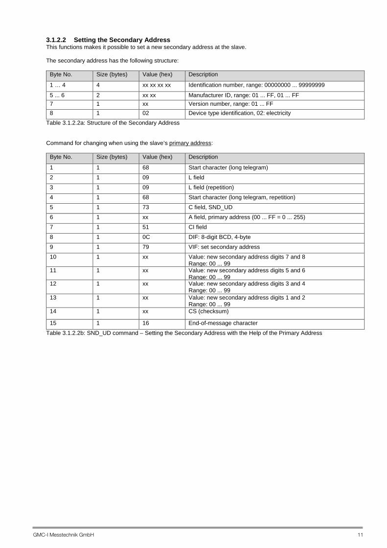
3.1.2.2 Setting the Secondary Address This functions makes it possible to set a new secondary address at the slave. The secondary address has the following structure:
Byte No. Size (bytes) Value (hex) Description
1 … 4 4 xx xx xx xx Identification number, range: 00000000 ... 99999999
5 ... 6 2 xx xx Manufacturer ID, range: 01 ... FF, 01 ... FF 7 1 xx Version number, range: 01 ... FF 8 1 02 Device type identification, 02: electricity
Table 3.1.2.2a: Structure of the Secondary Address Command for changing when using the slave’s primary address:
Byte No. Size (bytes) Value (hex) Description
1 1 68 Start character (long telegram) 2 1 09 L field 3 1 09 L field (repetition) 4 1 68 Start character (long telegram, repetition) 5 1 73 C field, SND_UD 6 1 xx A field, primary address (00 ... FF = 0 ... 255) 7 1 51 CI field 8 1 0C DIF: 8-digit BCD, 4-byte 9 1 79 VIF: set secondary address 10 1 xx Value: new secondary address digits 7 and 8
Range: 00 ... 99 11 1 xx Value: new secondary address digits 5 and 6
Range: 00 ... 99 12 1 xx Value: new secondary address digits 3 and 4
Range: 00 ... 99 13 1 xx Value: new secondary address digits 1 and 2
Range: 00 ... 99 14 1 xx CS (checksum)
15 1 16 End-of-message character Table 3.1.2.2b: SND_UD command – Setting the Secondary Address with the Help of the Primary Address

12 GMC-I Messtechnik GmbH
Command for changing when using the slave’s secondary address:
Byte No. Size (bytes)
Value (hex) Description
1 1 68 Start character (long telegram) 2 1 11 L field 3 1 11 L field (repetition) 4 1 68 Start character (long telegram, repetition) 5 1 73 C field, SND_UD 6 1 FD A field, primary address = 253, i.e. addressing via the secondary
address 7 1 51 CI field 8 … 15 8 xx xx xx xx xx xx xx xx Secondary address 16 1 0C DIF: 8-digit BCD, 4-byte 17 1 79 VIF: set secondary address 18 1 xx Value: new secondary address digits 7 and 8
Range: 00 ... 99 19 1 xx Value: new secondary address digits 5 and 6
Range: 00 ... 99 20 1 xx Value: new secondary address digits 3 and 4
Range: 00 ... 99 21 1 xx Value: new secondary address digits 1 and 2
Range: 00 ... 99 22 1 xx CS (checksum) 23 1 16 End-of-message character
Table 3.1.2.2c: SND_UD command – Setting the Secondary Address with the Help of the Secondary Address Response from the slave: E5h 3.1.2.3 Setting the Baud Rate This function makes it possible to change the baud rate of the M-Bus slave. The slave responds with the single character acknowledgement (E5h) with the old baud rate. As soon as the acknowledgement has ben sent, the slave is switched to the new baud rate. In order to assure that the salve has changed its baud rate correctly, the master must send a telegram to the slave with the new baud rate within 2 minutes. If the slave does not send an ACK after x attempts, the master must return to the old baud rate. Command when using the slave’s primary address:
Byte No. Size (bytes) Value (hex) Description
1 1 68 Start character (long telegram) 2 1 03 L field 3 1 03 L field (repetition) 4 1 68 Start character (long telegram, repetition) 5 1 73 C field, SND_UD 6 1 xx A field, primary address (00 ... FA = 0 ... 250 or 253, if selected)
7 1 xx CI field: set new baud rate B8: set baud rate to 300 baud B9: set baud rate to 600 baud BA: set baud rate to 1200 baud BB: set baud rate to 2400 baud BC: set baud rate to 4800 baud BD: set baud rate to 9600 baud
8 1 xx CS (checksum) 9 1 16 End-of-message character
Table 3.1.2.3a: SND_UD Command – Setting the Baud Rate with the Help of the Primary Address

GMC-I Messtechnik GmbH 13
Command for changing when using the slave’s secondary address:
Byte No. Size (bytes) Value (hex) Description
1 1 68 Start character (long telegram) 2 1 0B L field 3 1 0B L field (repetition) 4 1 68 Start character (long telegram, repetition) 5 1 73 C field, SND_UD 6 1 FD A field, primary address = 253, i.e. addressing via the
secondary address 7 1 xx CI field: set new baud rate
B8: set baud rate to 300 baud B9: set baud rate to 600 baud BA: set baud rate to 1200 baud BB: set baud rate to 2400 baud BC: set baud rate to 4800 baud BD: set baud rate to 9600 baud
8 … 15 8 xx xx xx xx xx xx xx xx Secondary address
16 1 xx CS (checksum)
17 1 16 End-of-message character Table 3.1.2.3a: SND_UD Command – Setting the Baud Rate with the Help of the Secondary Address Response from the slave: E5h 3.1.2.4 Setting the Active Tariff This function makes it possible to change the active tariff. Command when using the slave’s primary address:
Byte No. Size (bytes) Value (hex) Description 1 1 68 Start character (long telegram) 2 1 07 L field 3 1 07 L field (repetition) 4 1 68 Start character (long telegram, repetition) 5 1 73 C field, SND_UD 6 1 xx A field, primary address (00 ... FA = 0 ... 250 or 253, if selected) 7 1 51 CI field 8 1 01 DIF: 8-bit integer, 1 byte 9 1 FF VIF followed by manufacturer-specific VIFE 10 1 23 Manufacturer-specific VIFE: define tariff 11 1 xx Value:
00: tariff selection via hardware tariff input (default), see also operating instructions 01 … 08: tariff controlled via bus
12 1 xx CS (checksum) 13 1 16 End-of-message character
Table 3.1.2.4a

14 GMC-I Messtechnik GmbH
Command when using the slave’s secondary address:
Byte No.
Size (bytes)
Value (hex) Description
1 1 68 Start character (long telegram)
2 1 0F L field 3 1 0F L field (repetition) 4 1 68 Start character (long telegram, repetition) 5 1 73 C field, SND_UD 6 1 FD A field, primary address = 253, i.e. addressing via the secondary
address 7 1 51 CI field 8 ... 15 8 xx xx xx xx xx xx xx xx Secondary address
16 1 01 DIF: 8-bit integer, 1 byte 17 1 FF VIF followed by manufacturer-specific VIFE 18 1 23 Manufacturer-specific VIFE: define tariff 19 1 xx Value:
00: tariff selection via hardware tariff input (default), see also operating instructions 01 … 08: tariff controlled via bus
20 1 xx CS (checksum) 21 1 16 End-of-message character
Table 3.1.2.4b Response from the slave: E5h Important notes regarding tariff switching via the interface:
– Switching the tariff via the interface is not included in the scope of MID approval. – However, in order to initially specify the tariff via the interface (value: 1 - 8) after previous hardware
control (previous value: 0), the enable key on the device must first be pressed and the key must not appear at the device display. The setting is otherwise ignored! (If this is the case, switching back to 0 is required, after which the enable key must be pressed and the telegram must be sent again.)
– As long as the tariff is specified via the interface (value: 1 - 8), the tariff can always be changed with this telegram. In this state, the tariff can only be specified via the interface.
– Value 0 can be used to switch back to hardware control. – The currently selected tariff for energy metering is transmitted, for example, with the standard telegram,
and it can be read out with the Set Bit 16 parameter (see section “4.2 Parameter Set List − All Retrievable Values”). It appears continuously at the meter’s display as well.
– The tariff specified previously via the interface (this telegram) can be read out with the Set Bit 77 parameter: if a 0 is read (default), the tariff is controlled via the hardware inputs at the meter.

GMC-I Messtechnik GmbH 15
3.1.2.5 Setting Date and Time This function makes it possible to change date and time. Command when using the slave’s primary address:
Byte No. Size (bytes)
Value (hex) Description
1 1 68 Start character (long telegram) 2 1 0B L field 3 1 0B L field (repetition) 4 1 68 Start character (long telegram, repetition) 5 1 73 C field, SND_UD 6 1 xx A field, primary address (00 ... FA = 0 ... 250 or 253, if selected)
7 1 51 CI field
8 1 06 DIF: 48-bit, data field = 0110b, type I
9 1 6D VIF: extended date and point in time
10 … 15 1 xx xx xx xx xx xx Value: type I: date and time (CP48) (see table 3.1.4.10a) 16 1 xx CS (checksum) 17 1 16 End-of-message character
Table 3.1.2.5a Command when using the slave’s secondary address:
Byte No. Size (bytes)
Value (hex) Description
1 1 68 Start character (long telegram) 2 1 13 L field 3 1 13 L field (repetition) 4 1 68 Start character (long telegram, repetition) 5 1 73 C field, SND_UD 6 1 FD A field, primary address = 253, i.e. addressing via the secondary
address 7 1 51 CI field 8 ... 15 8 xx xx xx xx xx xx xx xx Secondary address 16 1 06 DIF: 48-bit, data field = 0110b, type I 17 1 6D VIF: extended date and point in time 18 ... 23 1 xx xx xx xx xx xx Value: type I: date and time (CP48) (see table 3.1.4.10a) 24 1 xx CS (checksum) 25 1 16 End-of-message character
Table 3.1.2.5b Response from the slave: E5h
16 GMC-I Messtechnik GmbH
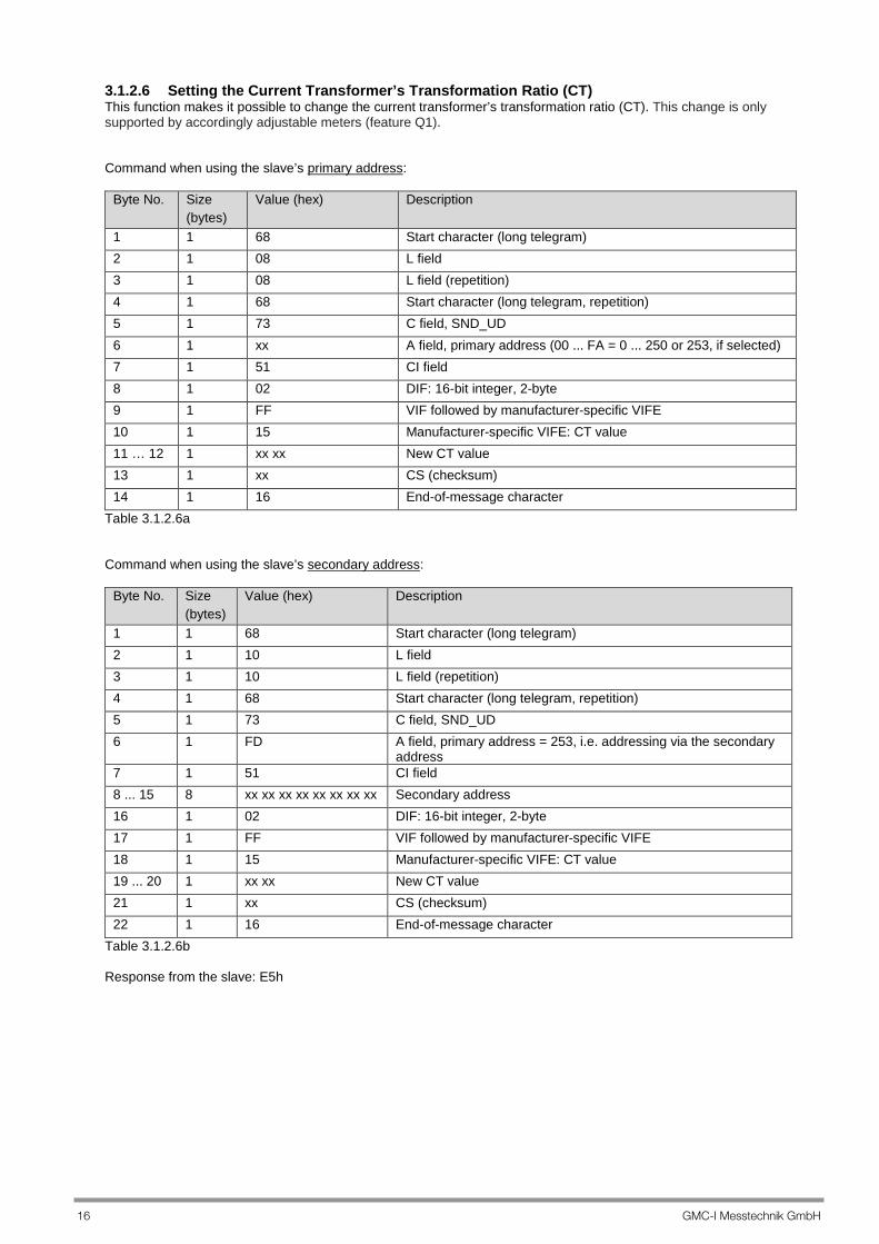
3.1.2.6 Setting the Current Transformer’s Transformation Ratio (CT) This function makes it possible to change the current transformer’s transformation ratio (CT). This change is only supported by accordingly adjustable meters (feature Q1). Command when using the slave’s primary address:
Byte No. Size (bytes)
Value (hex) Description
1 1 68 Start character (long telegram) 2 1 08 L field 3 1 08 L field (repetition) 4 1 68 Start character (long telegram, repetition) 5 1 73 C field, SND_UD 6 1 xx A field, primary address (00 ... FA = 0 ... 250 or 253, if selected) 7 1 51 CI field 8 1 02 DIF: 16-bit integer, 2-byte 9 1 FF VIF followed by manufacturer-specific VIFE 10 1 15 Manufacturer-specific VIFE: CT value 11 … 12 1 xx xx New CT value 13 1 xx CS (checksum) 14 1 16 End-of-message character
Table 3.1.2.6a Command when using the slave’s secondary address:
Byte No. Size (bytes)
Value (hex) Description
1 1 68 Start character (long telegram) 2 1 10 L field 3 1 10 L field (repetition) 4 1 68 Start character (long telegram, repetition) 5 1 73 C field, SND_UD 6 1 FD A field, primary address = 253, i.e. addressing via the secondary
address 7 1 51 CI field 8 ... 15 8 xx xx xx xx xx xx xx xx Secondary address 16 1 02 DIF: 16-bit integer, 2-byte 17 1 FF VIF followed by manufacturer-specific VIFE 18 1 15 Manufacturer-specific VIFE: CT value 19 ... 20 1 xx xx New CT value 21 1 xx CS (checksum) 22 1 16 End-of-message character
Table 3.1.2.6b Response from the slave: E5h

GMC-I Messtechnik GmbH 17
3.1.2.7 Setting the Voltage Transformer’s Transformation Ratio This function makes it possible to change the voltage transformer’s transformation ratio (VT). This change is only supported by accordingly adjustable meters (feature Q1). Command when using the slave’s primary address:
Byte No. Size (bytes)
Value (hex) Description
1 1 68 Start character (long telegram) 2 1 08 L field 3 1 08 L field (repetition) 4 1 68 Start character (long telegram, repetition) 5 1 73 C field, SND_UD 6 1 xx A field, primary address (00 ... FA = 0 ... 250 or 253, if selected)
7 1 51 CI field
8 1 02 DIF: 16-bit integer, 2-byte
9 1 FF VIF followed by manufacturer-specific VIFE
10 1 16 Manufacturer-specific VIFE: VT value
11 … 12 1 xx xx New VT value
13 1 xx CS (checksum)
14 1 16 End-of-message character Table 3.1.2.7a Command when using the slave’s secondary address:
Byte No.
Size (bytes)
Value (hex) Description
1 1 68 Start character (long telegram) 2 1 10 L field 3 1 10 L field (repetition) 4 1 68 Start character (long telegram, repetition) 5 1 73 C field, SND_UD 6 1 FD A field, primary address = 253, i.e. addressing via the secondary
address 7 1 51 CI field 8 ... 15 8 xx xx xx xx xx xx xx xx Secondary address 16 1 02 DIF: 16-bit integer, 2-byte 17 1 FF VIF followed by manufacturer-specific VIFE 18 1 16 Manufacturer-specific VIFE: VT value 19 ... 20
1 xx xx New VT value
21 1 xx CS (checksum) 22 1 16 End-of-message character
Table 3.1.2.7b Response from the slave: E5h
18 GMC-I Messtechnik GmbH
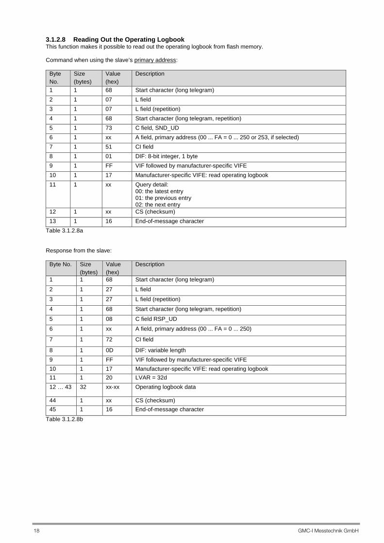
3.1.2.8 Reading Out the Operating Logbook This function makes it possible to read out the operating logbook from flash memory. Command when using the slave’s primary address:
Byte No.
Size (bytes)
Value (hex)
Description
1 1 68 Start character (long telegram) 2 1 07 L field 3 1 07 L field (repetition) 4 1 68 Start character (long telegram, repetition) 5 1 73 C field, SND_UD 6 1 xx A field, primary address (00 ... FA = 0 ... 250 or 253, if selected) 7 1 51 CI field 8 1 01 DIF: 8-bit integer, 1 byte 9 1 FF VIF followed by manufacturer-specific VIFE 10 1 17 Manufacturer-specific VIFE: read operating logbook 11 1 xx Query detail:
00: the latest entry 01: the previous entry 02: the next entry
12 1 xx CS (checksum) 13 1 16 End-of-message character
Table 3.1.2.8a Response from the slave:
Byte No. Size (bytes)
Value (hex)
Description
1 1 68 Start character (long telegram) 2 1 27 L field 3 1 27 L field (repetition) 4 1 68 Start character (long telegram, repetition)
5 1 08 C field RSP_UD 6 1 xx A field, primary address (00 ... FA = 0 ... 250)
7 1 72 CI field
8 1 0D DIF: variable length 9 1 FF VIF followed by manufacturer-specific VIFE 10 1 17 Manufacturer-specific VIFE: read operating logbook 11 1 20 LVAR = 32d 12 … 43 32 xx-xx Operating logbook data
44 1 xx CS (checksum) 45 1 16 End-of-message character
Table 3.1.2.8b
GMC-I Messtechnik GmbH 19
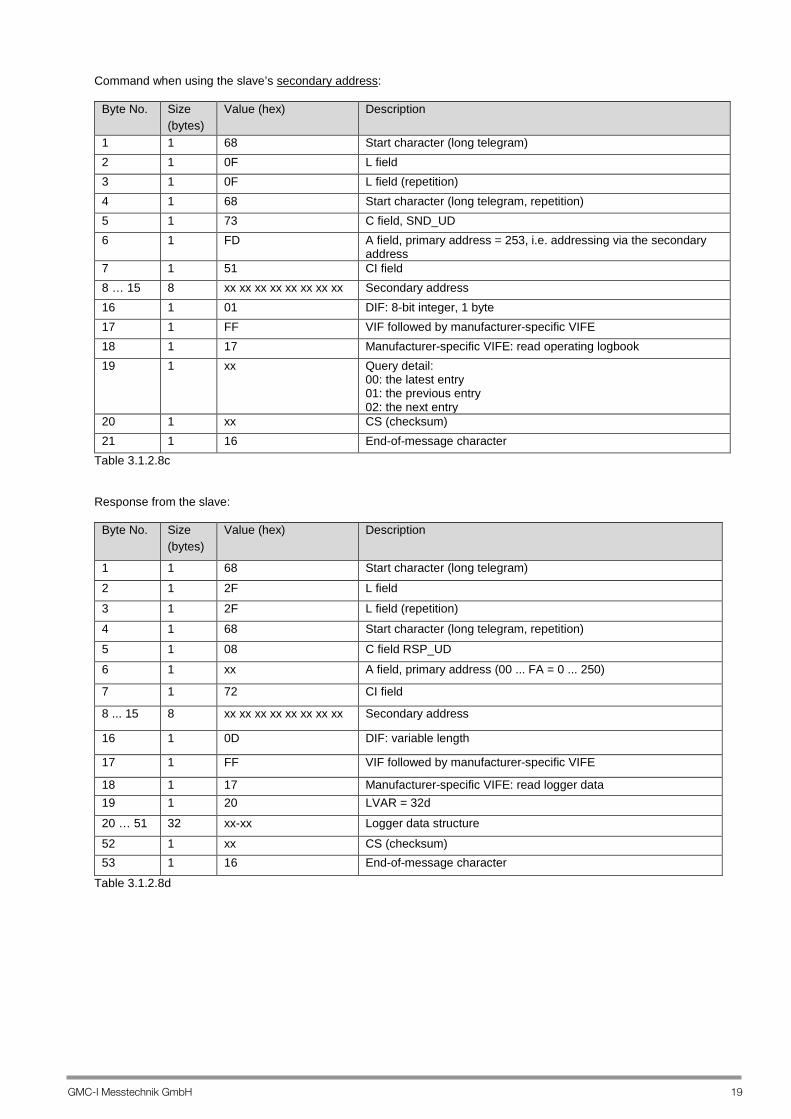
Command when using the slave’s secondary address:
Byte No. Size (bytes)
Value (hex) Description
1 1 68 Start character (long telegram) 2 1 0F L field 3 1 0F L field (repetition) 4 1 68 Start character (long telegram, repetition) 5 1 73 C field, SND_UD 6 1 FD A field, primary address = 253, i.e. addressing via the secondary
address 7 1 51 CI field 8 … 15 8 xx xx xx xx xx xx xx xx Secondary address 16 1 01 DIF: 8-bit integer, 1 byte 17 1 FF VIF followed by manufacturer-specific VIFE 18 1 17 Manufacturer-specific VIFE: read operating logbook 19 1 xx Query detail:
00: the latest entry 01: the previous entry 02: the next entry
20 1 xx CS (checksum) 21 1 16 End-of-message character
Table 3.1.2.8c Response from the slave:
Byte No. Size (bytes)
Value (hex) Description
1 1 68 Start character (long telegram) 2 1 2F L field
3 1 2F L field (repetition) 4 1 68 Start character (long telegram, repetition) 5 1 08 C field RSP_UD 6 1 xx A field, primary address (00 ... FA = 0 ... 250)
7 1 72 CI field
8 ... 15 8 xx xx xx xx xx xx xx xx Secondary address
16 1 0D DIF: variable length
17 1 FF VIF followed by manufacturer-specific VIFE
18 1 17 Manufacturer-specific VIFE: read logger data 19 1 20 LVAR = 32d
20 … 51 32 xx-xx Logger data structure
52 1 xx CS (checksum) 53 1 16 End-of-message character
Table 3.1.2.8d

20 GMC-I Messtechnik GmbH
Logger Data Structure Definition
Table 3.1.2.8e
Event Code Beginning
Event Code End Description Parameter
00h Status OK 01h 81h Current too high Phase number (par 1) 02h 82h Voltage too high Phase number (par 1) 03h 83h No frequency synchronization 04h 84h Frequency too low 05h 85h Frequency too high 06h 86h Incorrect phase sequence 07h 87h Unknown phase sequence 08h 88h Device is not calibrated 09h 89h Phase voltage too low Phase number (par 1) 0Ah 8Ah Analog error 0Bh 8Bh Energy error 0Ch 8Ch Internal communication error 40h Date/time changed New date/time saved
(format 8 in par 1 ... 7) 48h CT changed New CT value saved (par 1) 49h VT changed New VT value saved (par 1) 60h Reset has occurred without saving
date and time
61h Mains failure has occurred Table 3.1.2.8f
Byte Index Variable Format 0 Record index UINT16 2 Event code UINT8 3 Parameter (1) UINT8 4 Parameter (2) UINT8 5 Parameter (3) UINT8 6 Parameter (4) UINT8 7 Parameter (5) UINT8 8 Parameter (6) UINT8 9 Parameter (7) UINT8 10 Operating hours UINT32 14 Event time RTC 22 ... 31 Reserve ------

GMC-I Messtechnik GmbH 21
3.1.2.9 Reading Out Load Profile Data (with feature Z1 only) This function makes it possible to read out load profile data from the device’s internal memory. Command when using the slave’s primary address:
Byte No.
Size (bytes)
Value (hex)
Description
1 1 68 Start character (long telegram)
2 1 07 L field 3 1 07 L field (repetition) 4 1 68 Start character (long telegram, repetition) 5 1 73 C field, SND_UD 6 1 xx A field, primary address (00 ... FA = 0 ... 250 or 253, if selected)
7 1 51 CI field
8 1 01 DIF: 8-bit integer, 1 byte
9 1 FF VIF followed by manufacturer-specific VIFE
10 1 18 Manufacturer-specific VIFE: read load profile data
11 1 xx Query detail: 00: the latest entry 01: the previous entry 02: the next entry
12 1 xx CS (checksum) 13 1 16 End-of-message character
Table 3.1.2.9a Response from the slave:
Byte No. Size (bytes)
Value (hex)
Description
1 1 68 Start character (long telegram) 2 1 47 L field 3 1 47 L field (repetition)
4 1 68 Start character (long telegram, repetition) 5 1 08 C field RSP_UD 6 1 xx A field, primary address (00 ... FA = 0 ... 250)
7 1 72 CI field
8 1 0D DIF: variable length
9 1 FF VIF followed by manufacturer-specific VIFE
10 1 18 Manufacturer-specific VIFE: read load profile data
11 1 40 LVAR = 64d
12 … 75 64 xx-xx Load profile data
76 1 xx CS (checksum)
77 1 16 End-of-message character Table 3.1.2.9b

22 GMC-I Messtechnik GmbH
Command when using the slave’s secondary address:
Byte No. Size (bytes)
Value (hex) Description
1 1 68 Start character (long telegram) 2 1 0F L field 3 1 0F L field (repetition) 4 1 68 Start character (long telegram, repetition) 5 1 73 C field, SND_UD 6 1 FD A field, primary address = 253, i.e. addressing via the
secondary address 7 1 51 CI field 8 … 15 8 xx xx xx xx xx xx xx xx Secondary address 16 1 01 DIF: 8-bit integer, 1 byte 17 1 FF VIF followed by manufacturer-specific VIFE 18 1 18 Manufacturer-specific VIFE: read load profile data 19 1 xx Query detail:
00: the latest entry 01: the previous entry 02: the next entry
20 1 xx CS (checksum) 21 1 16 End-of-message character
Table 3.1.2.9c Response from the slave:
Byte No. Size (bytes)
Value (hex) Description
1 1 68 Start character (long telegram) 2 1 4F L field 3 1 4F L field (repetition) 4 1 68 Start character (long telegram, repetition) 5 1 08 C field RSP_UD 6 1 xx A field, primary address (00 ... FA = 0 ... 250) 7 1 72 CI field 8 ... 15 8 xx xx xx xx xx xx xx
Secondary address
16 1 0D DIF: variable length 17 1 FF VIF followed by manufacturer-specific VIFE 18 1 18 Manufacturer-specific VIFE: read load profile data 19 1 40 LVAR = 64d 20 ... 83 64 xx-xx Load profile data 84 1 xx CS (checksum) 85 1 16 End-of-message character
Table 3.1.2.9d

GMC-I Messtechnik GmbH 23
Load profile data structure: The structure consists of 64 bytes.
Byte Index Variable Format 0 Entry number UINT16 2 Active tariff UINT8 3 Exponent for energy SINT8 4 Calibratable active energy import (all phases) (mantissa 1) UINT32 8 Calibratable active energy supply (all phases) (mantissa 1) UINT32 12 Calibratable reactive energy import (all phases) (mantissa 1) UINT32 16 Calibratable reactive energy supply (all phases) (mantissa 1) UINT32 20 Two further decimal places, active energy import (mantissa 2) UINT8 21 Two further decimal places, active energy supply (mantissa 2) UINT8 22 Two further decimal places, reactive energy import (mantissa 2) UINT8 23 Two further decimal places, reactive energy supply (mantissa 2) UINT8 24 Load profile status 1 LS1 26 Load profile status 2 LS2 28 Time stamp RTC 36 Load profile interval (1, 2, 3, 4, 5, 10, 15, 30, 60 min.) UINT8 37 ... 63 Reserve (values not defined) -
Table 3.1.2.9e Note: All energy values are calculated as follows: Display accuracy: Energy = mantissa 1 * 10 ^ exponent register [Wh] or [VArh] Increased accuracy: Energy = mantissa 1 * 10 ^ exponent register + mantissa 2 * 10 ^ (exponent_for_energy-2) [Wh] or [VArh] Calibratable energy is always saved to memory: the CT and VT values must be subsequently multiplied in the case of feature Q1 (adjustable CT and VT values, calibratable secondary energy). Example: Mantissa 1 of 4561 and mantissa 2 of 24 and exponent +3 is read as: Mantissa 1, register: Mantissa 2, register: Exponent register: 4561 * 10 ^ (3) + 24 * 10 ^ (1) = 4,561,240 Wh
00h 00h 11h D5h
00h 18h
03h

24 GMC-I Messtechnik GmbH
Load Profile Status The load profile status registers display events which have occurred during the load profile interval. Load profile status 1: bits 0 ... 15 come from the operating logbook for events which have occurred during the load profile interval. If the load profile logger entry is incomplete (after reset, tariff change or time change), this is indicated by the “incomplete load profile interval” status bit. If a reset has occurred, for example in the case of a restart after a power failure, this is indicated in the first load profile entry by means of the “reset occurred” status bit (and incomplete load profile logger interval). If the tariff is changed, the current load profile logger value (asynchronous entry) at the point in time of the tariff change is saved with the information “tariff change”. A new load profile interval is then started with the new tariff. As a result, no energy values can be lost (the entry after the tariff change and the next entry are flagged with the “incomplete load profile interval” status bit). If time is changed, the current load profile logger value (asynchronous entry) is saved with the “time changed – asynchronous load profile entry” status bit with the previous time stamp, after which a new load profile logger period is started with the new time. As a result, no energy values can be lost (the entry after the tariff change and the next entry are flagged with the “incomplete load profile interval” status bit). 15 14 13 12 11 10 9 8 7 6 5 4 3 2 1 0 MSB

GMC-I Messtechnik GmbH 25
Load Profile Status 1 Status Bit Description 0 Current too high, phase 1 1 Current too high, phase 2 2 Current too high, phase 3 3 Voltage too high, phase 1 4 Voltage too high, phase 2 5 Voltage too high, phase 3 6 No frequency synchronization 7 Frequency too low 8 Frequency too high 9 Counterclockwise phase sequence 10 Unknown phase sequence 11 Device is not calibrated 12 Analog error 13 Energy error 14 Internal communication error 15 Energy restored – the energy value has been restored from cyclical backups. Table 3.1.2.9f Load Profile Status 2 Status Bit Description 0 Incomplete load profile interval 1 Reset occurred 2 Tariff changed – asynchronous load profile entry 3 Time changed – asynchronous load profile entry 4 - 5 - 6 - 7 - 8 - 9 - 10 - 11 - 12 - 13 - 14 - 15 - Table 3.1.2.9g RTC Format Structure of the RTC command (date and time):
Variable Format
Seconds UINT8 Minutes UINT8 Hours UINT8 Day UINT8 Month UINT8 Year UINT16
Table 3.1.2.9h
26 GMC-I Messtechnik GmbH
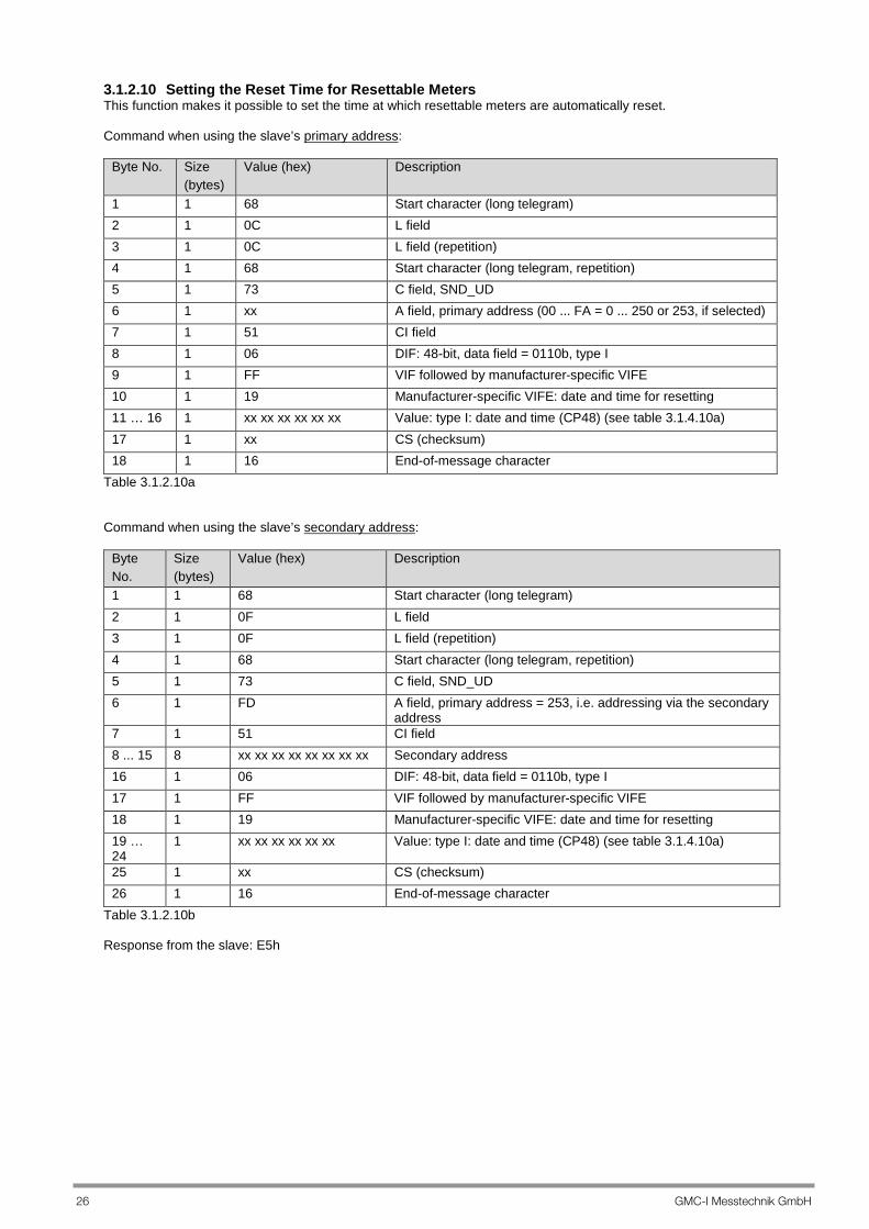
3.1.2.10 Setting the Reset Time for Resettable Meters This function makes it possible to set the time at which resettable meters are automatically reset. Command when using the slave’s primary address:
Byte No. Size (bytes)
Value (hex) Description
1 1 68 Start character (long telegram) 2 1 0C L field 3 1 0C L field (repetition) 4 1 68 Start character (long telegram, repetition) 5 1 73 C field, SND_UD 6 1 xx A field, primary address (00 ... FA = 0 ... 250 or 253, if selected) 7 1 51 CI field 8 1 06 DIF: 48-bit, data field = 0110b, type I 9 1 FF VIF followed by manufacturer-specific VIFE 10 1 19 Manufacturer-specific VIFE: date and time for resetting 11 … 16 1 xx xx xx xx xx xx Value: type I: date and time (CP48) (see table 3.1.4.10a) 17 1 xx CS (checksum) 18 1 16 End-of-message character
Table 3.1.2.10a Command when using the slave’s secondary address:
Byte No.
Size (bytes)
Value (hex) Description
1 1 68 Start character (long telegram) 2 1 0F L field 3 1 0F L field (repetition) 4 1 68 Start character (long telegram, repetition) 5 1 73 C field, SND_UD 6 1 FD A field, primary address = 253, i.e. addressing via the secondary
address 7 1 51 CI field 8 ... 15 8 xx xx xx xx xx xx xx xx Secondary address 16 1 06 DIF: 48-bit, data field = 0110b, type I 17 1 FF VIF followed by manufacturer-specific VIFE 18 1 19 Manufacturer-specific VIFE: date and time for resetting 19 … 24
1 xx xx xx xx xx xx Value: type I: date and time (CP48) (see table 3.1.4.10a)
25 1 xx CS (checksum) 26 1 16 End-of-message character
Table 3.1.2.10b Response from the slave: E5h
GMC-I Messtechnik GmbH 27
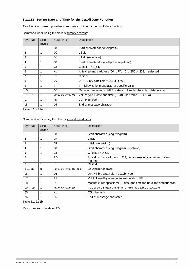
3.1.2.11 Setting Date and Time for the Cutoff Date Function This function makes it possible to set date and time for the cutoff date function. Command when using the slave’s primary address:
Byte No. Size (bytes)
Value (hex) Description
1 1 68 Start character (long telegram) 2 1 0C L field 3 1 0C L field (repetition) 4 1 68 Start character (long telegram, repetition) 5 1 73 C field, SND_UD 6 1 xx A field, primary address (00 ... FA = 0 ... 250 or 253, if selected) 7 1 51 CI field 8 1 06 DIF: 48-bit, data field = 0110b, type I 9 1 FF VIF followed by manufacturer-specific VIFE 10 1 1C Manufacturer-specific VIFE: date and time for the cutoff date function 11 … 16 1 xx xx xx xx xx xx Value: type I: date and time (CP48) (see table 3.1.4.10a) 17 1 xx CS (checksum) 18 1 16 End-of-message character
Table 3.1.2.11a Command when using the slave’s secondary address:
Byte No. Size (bytes)
Value (hex) Description
1 1 68 Start character (long telegram) 2 1 0F L field 3 1 0F L field (repetition) 4 1 68 Start character (long telegram, repetition) 5 1 73 C field, SND_UD 6 1 FD A field, primary address = 253, i.e. addressing via the secondary
address 7 1 51 CI field 8 … 15 8 xx xx xx xx xx xx xx xx Secondary address 16 1 06 DIF: 48-bit, data field = 0110b, type I 17 1 FF VIF followed by manufacturer-specific VIFE 18 1 1C Manufacturer-specific VIFE: date and time for the cutoff date function 19 … 24 1 xx xx xx xx xx xx Value: type I: date and time (CP48) (see table 3.1.4.10a) 25 1 xx CS (checksum) 26 1 16 End-of-message character
Table 3.1.2.11b Response from the slave: E5h

28 GMC-I Messtechnik GmbH
3.1.2.12 Setting the Load Profile Period This command is used to set the load profile period. Command when using the slave’s primary address:
Byte No.
Size (bytes)
Value (hex) Description
1 1 68 Start character (long telegram) 2 1 07 L field 3 1 07 L field (repetition) 4 1 68 Start character (long telegram, repetition) 5 1 73 C field, SND_UD 6 1 xx A field, primary address (00 ... FA = 0 ... 250 or 253, if selected) 7 1 51 CI field 8 1 01 DIF: 8-bit integer, 1 byte 9 1 FF VIF followed by manufacturer-specific VIFE 10 1 1A Manufacturer-specific VIFE: load profile integrating period 11 1 xx New value for the load profile integrating period 12 1 xx CS (checksum) 13 1 16 End-of-message character
Table 3.1.2.12a Command when using the slave’s secondary address:
Byte No.
Size (bytes)
Value (hex) Description
1 1 68 Start character (long telegram) 2 1 0F L field 3 1 0F L field (repetition) 4 1 68 Start character (long telegram, repetition) 5 1 73 C field, SND_UD 6 1 FD A field, primary address = 253, i.e. addressing via the
secondary address 7 1 51 CI field 8 … 15 8 xx xx xx xx xx xx xx xx Secondary address 16 1 01 DIF: 8-bit integer, 1 byte 17 1 FF VIF followed by manufacturer-specific VIFE 18 1 1A Manufacturer-specific VIFE: load profile integrating period 19 1 xx New value for the load profile integrating period 20 1 xx CS (checksum) 21 1 16 End-of-message character
Table 3.1.2.12b Response from the slave: E5h

GMC-I Messtechnik GmbH 29
3.1.2.13 Selecting a Slave with the Help of the Secondary Address Command for selecting the slave via the secondary address:
Byte No.
Size (bytes)
Value (hex) Description
1 1 68 Start character (long telegram) 2 1 0B L field
3 1 0B L field (repetition) 4 1 68 Start character (long telegram, repetition) 5 1 73 C field, SND_UD 6 1 FD A field, primary address = 253, i.e. addressing via the secondary
address 7 1 52 CI field
8 ... 15 8 xx xx xx xx xx xx xx xx Secondary address UD (see relevant section) 16 1 xx CS (checksum) 17 1 16 End-of-message character
Table 3.1.2.13: SND_UD Command: Selecting a Slave with the Help of the Secondary Address Response from the slave: E5h This telegram selects an M-Bus slave. After receiving REQ_UD2 with FD in the A field, a selected M-Bus slave is ready to transmit all data. The M-Bus slave also accepts all telegrams with primary address FD (FD in the A field) in this mode. In the following cases, the M-Bus slave is switched back to the normal mode:
− The M-Bus slave is switched off. − The M-Bus slave receives an invalid telegram. − The M-Bus slave receives a telegram for “initialization of the M-Bus slave” (SND_NKE).

30 GMC-I Messtechnik GmbH
3.1.2.14 Setting Parameter Masks This function makes it possible to select the data to be read out from the slave. All data can be read out, the desired data can be selected or a default mask can be selected which contains various types of data. Up to M bus firmware V1.15: The parameter masks are preserved until a reset is effected. Afterwards, the standard telegram is set again, see section 4.3. Standard Telegram. As from M bus firmware V1.15, the parameter masks are stored permanently, the set telegram is thus permanently preserved. Please note section 5.4. Set Telegram and 5.5. ENERGYMID Tool.

GMC-I Messtechnik GmbH 31
Read out all data: Command when using the slave’s primary address:
Byte No.
Size (bytes)
Value (hex) Description
1 1 68 Start character (long telegram) 2 1 04 L field 3 1 04 L field (repetition) 4 1 68 Start character (long telegram, repetition) 5 1 73 C field, SND_UD 6 1 xx A field, primary address (00 ... FA = 0 … 250, 253 or 255) 7 1 51 CI field 8 1 7F DIF: read out all data 9 1 xx CS (checksum) 10 1 16 End-of-message character
Table 3.1.2.14a: SND_UD Command: Reading Out All Data with the Help of the Primary Address Command when using the slave’s secondary address:
Byte No. Size (bytes)
Value (hex) Description
1 1 68 Start character (long telegram) 2 1 0C L field 3 1 0C L field (repetition) 4 1 68 Start character (long telegram, repetition) 5 1 73 C field, SND_UD 6 1 FD A field, primary address = 253, i.e. addressing via the
secondary address 7 1 51 CI field 8 … 15 8 xx xx xx xx xx xx xx xx Secondary address 16 1 7F DIF: query, read out all data 17 1 xx CS (checksum) 18 1 16 End-of-message character
Table 3.1.2.14b: SND_UD Command: Reading Out All Data with the Help of the Secondary Address Response from the slave: E5h

32 GMC-I Messtechnik GmbH
Read out desired data: Command when using the slave’s primary address:
Byte No.
Size (bytes) Value (hex)
Description
1 1 68 Start character (long telegram) 2 1 13 L field 3 1 13 L field (repetition) 4 1 68 Start character (long telegram, repetition) 5 1 73 C field, SND_UD 6 1 xx A field, primary address (00..FA, FD, FF = 0..250, 253, 255) 7 1 51 CI field 8 1 0D DIF: variable length 9 1 FD VIF followed by standard VIFE 10 1 0B VIFE: parameter mask identification 11 1 0C LVAR=12 12 1 “PS0” Selected parameter from parameter mask 0 13 1 “PS1” Selected parameter from parameter mask 1 14 1 “PS2” Selected parameter from parameter mask 2 15 1 “PS3” Selected parameter from parameter mask 3 16 1 “PS4” Selected parameter from parameter mask 4 17 1 “PS5” Selected parameter from parameter mask 5 18 1 “PS6” Selected parameter from parameter mask 6 19 1 “PS7” Selected parameter from parameter mask 7 20 1 “PS8” Selected parameter from parameter mask 8 21 1 “PS9” Selected parameter from parameter mask 9 22 1 “PS10” Selected parameter from parameter mask 10 23 1 “PS11” Selected parameter from parameter mask 11 24 1 Xx CS (checksum) 25 1 16 End-of-message character
Table 3.1.2.14c: SND_UD Command: Reading Out Desired Data with the Help of the Primary Address In order to set the parameter mask for all M-Bus interfaces, primary address 255 (FFh) must be used in the A field. In this case, the M-Bus interfaces don’t send an acknowledgement telegram (E5h). See section 4.3. Standard Telegram concerning the default parameter mask for single frame communication after a START or a RESET.

GMC-I Messtechnik GmbH 33
Command when using the slave’s secondary address:
Byte No.
Size (bytes)
Value (hex) Description
1 1 68 Start character (long telegram) 2 1 1B L field 3 1 1B L field (repetition) 4 1 68 Start character (long telegram, repetition) 5 1 73 C field, SND_UD 6 1 FD A field, primary address = 253, i.e. addressing via the secondary address 7 1 51 CI field 8 ... 15 8 xx xx xx xx xx xx xx xx Secondary address (see relevant section) 16 1 0D DIF: variable length 17 1 FD VIF followed by standard VIFE 18 1 0B VIFE: parameter set identification 19 1 0C LVAR=12 20 1 “PS0” Selected parameter from parameter mask 0 21 1 “PS1” Selected parameter from parameter mask 1 22 1 “PS2” Selected parameter from parameter mask 2 23 1 “PS3” Selected parameter from parameter mask 3 24 1 “PS4” Selected parameter from parameter mask 4 25 1 “PS5” Selected parameter from parameter mask 5 26 1 “PS6” Selected parameter from parameter mask 6 27 1 “PS7” Selected parameter from parameter mask 7 28 1 “PS8” Selected parameter from parameter mask 8 29 1 “PS9” Selected parameter from parameter mask 9 30 1 “PS10” Selected parameter from parameter mask 10 31 1 “PS11” Selected parameter from parameter mask 11 32 1 Xx CS (checksum) 33 1 16 End-of-message character
Table 3.1.2.14d: SND_UD Command: Reading Out Desired Data with the Help of the Secondary Address Response from the slave: E5h Default parameter mask for the Single Frame communication after START or RESET see section 4.3. Standard Telegram. Please note sections 5.4. Set Telegram and 5.5. ENERGYMID Tool.

34 GMC-I Messtechnik GmbH
Temporary Read-out of the Desired Files: Applicable as from M bus firmware version V1.15. With this mask the data can be read out temporarily. The protocol is not changed permanently. This protocol is used for communication by the ENERGYMID tool. Command for Using the Primary Address of the Slaves:
Byte No.
Size (Byte)
Value (hex)
Description
1 1 68 Start character (long telegram) 2 1 13 L field 3 1 13 L field (repetition) 4 1 68 Start character (long telegram, repetition) 5 1 73 C field, SND_UD 6 1 xx A field, primary address (00..FA, FD, FF = 0..250, 253, 255 and FF = 255) 7 1 51 CI field 8 1 0D DIF: variable length 9 1 FF VIF: followed by standard VIFE 10 1 51 VIFE: parameter set identification 11 1 0C LVAR=12 12 1 “PS0” Selected parameter from parameter mask 0 13 1 “PS1” Selected parameter from parameter mask 1 14 1 “PS2” Selected parameter from parameter mask 2 15 1 “PS3” Selected parameter from parameter mask 3 16 1 “PS4” Selected parameter from parameter mask 4 17 1 “PS5” Selected parameter from parameter mask 5 18 1 “PS6” Selected parameter from parameter mask 6 19 1 “PS7” Selected parameter from parameter mask 7 20 1 “PS8” Selected parameter from parameter mask 8 21 1 “PS9” Selected parameter from parameter mask 9 22 1 “PS10” Selected parameter from parameter mask 10 23 1 “PS11” Selected parameter from parameter mask 11 24 1 xx CS (checksum) 25 1 16 End-of-message character
Table 3.1.2.14c – SND_UD Command: Reading Out Desired Data with the Help of the Primary Address
GMC-I Messtechnik GmbH 35
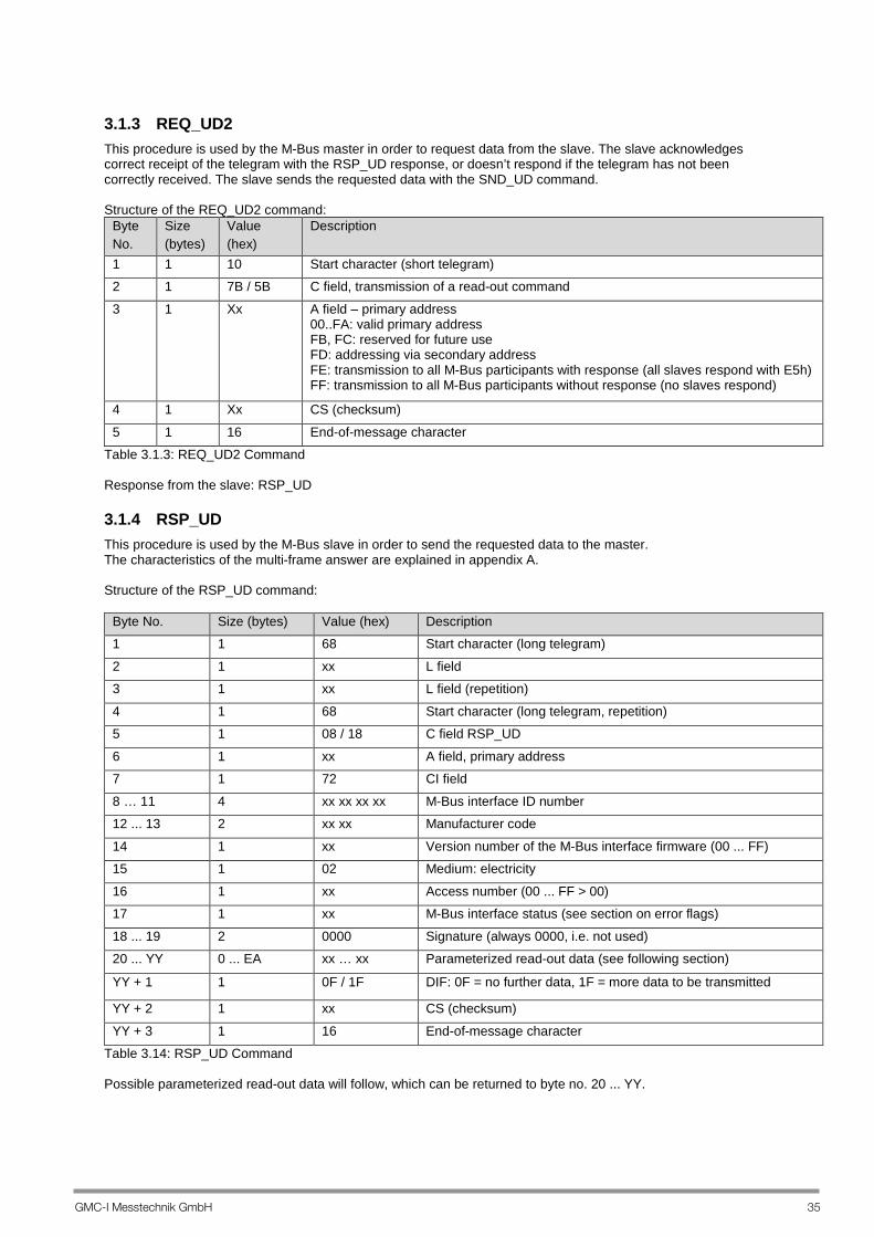
3.1.3 REQ_UD2 This procedure is used by the M-Bus master in order to request data from the slave. The slave acknowledges correct receipt of the telegram with the RSP_UD response, or doesn’t respond if the telegram has not been correctly received. The slave sends the requested data with the SND_UD command. Structure of the REQ_UD2 command:
Byte No.
Size (bytes)
Value (hex)
Description
1 1 10 Start character (short telegram) 2 1 7B / 5B C field, transmission of a read-out command
3 1 Xx A field – primary address 00..FA: valid primary address FB, FC: reserved for future use FD: addressing via secondary address FE: transmission to all M-Bus participants with response (all slaves respond with E5h) FF: transmission to all M-Bus participants without response (no slaves respond)
4 1 Xx CS (checksum)
5 1 16 End-of-message character Table 3.1.3: REQ_UD2 Command Response from the slave: RSP_UD
3.1.4 RSP_UD This procedure is used by the M-Bus slave in order to send the requested data to the master. The characteristics of the multi-frame answer are explained in appendix A. Structure of the RSP_UD command:
Byte No. Size (bytes) Value (hex) Description 1 1 68 Start character (long telegram)
2 1 xx L field 3 1 xx L field (repetition)
4 1 68 Start character (long telegram, repetition) 5 1 08 / 18 C field RSP_UD
6 1 xx A field, primary address 7 1 72 CI field
8 … 11 4 xx xx xx xx M-Bus interface ID number 12 ... 13 2 xx xx Manufacturer code
14 1 xx Version number of the M-Bus interface firmware (00 ... FF) 15 1 02 Medium: electricity
16 1 xx Access number (00 ... FF > 00) 17 1 xx M-Bus interface status (see section on error flags)
18 ... 19 2 0000 Signature (always 0000, i.e. not used) 20 ... YY 0 ... EA xx … xx Parameterized read-out data (see following section)
YY + 1 1 0F / 1F DIF: 0F = no further data, 1F = more data to be transmitted
YY + 2 1 xx CS (checksum)
YY + 3 1 16 End-of-message character Table 3.14: RSP_UD Command Possible parameterized read-out data will follow, which can be returned to byte no. 20 ... YY.
36 GMC-I Messtechnik GmbH
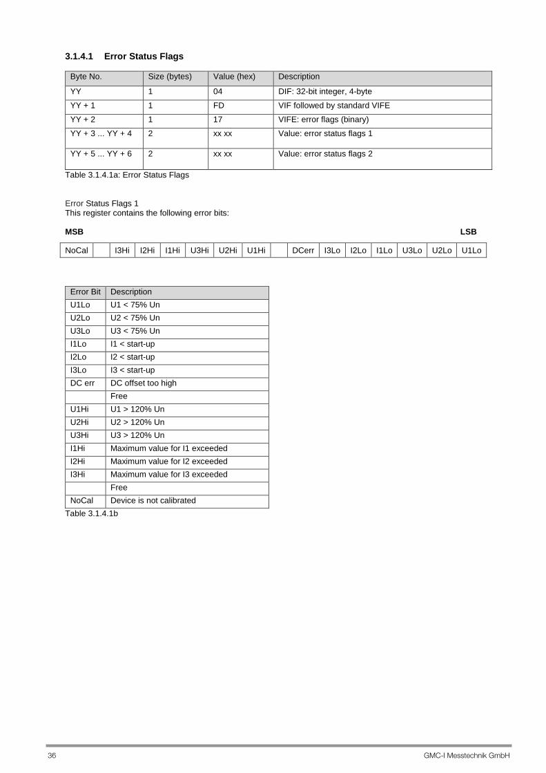
3.1.4.1 Error Status Flags
Byte No. Size (bytes) Value (hex) Description
YY 1 04 DIF: 32-bit integer, 4-byte YY + 1 1 FD VIF followed by standard VIFE YY + 2 1 17 VIFE: error flags (binary) YY + 3 ... YY + 4 2 xx xx Value: error status flags 1
YY + 5 ... YY + 6 2 xx xx Value: error status flags 2
Table 3.1.4.1a: Error Status Flags Error Status Flags 1 This register contains the following error bits: MSB LSB
Error Bit Description U1Lo U1 < 75% Un U2Lo U2 < 75% Un U3Lo U3 < 75% Un I1Lo I1 < start-up I2Lo I2 < start-up I3Lo I3 < start-up DC err DC offset too high Free U1Hi U1 > 120% Un U2Hi U2 > 120% Un U3Hi U3 > 120% Un I1Hi Maximum value for I1 exceeded I2Hi Maximum value for I2 exceeded I3Hi Maximum value for I3 exceeded Free NoCal Device is not calibrated
Table 3.1.4.1b
NoCal I3Hi I2Hi I1Hi U3Hi U2Hi U1Hi DCerr I3Lo I2Lo I1Lo U3Lo U2Lo U1Lo
GMC-I Messtechnik GmbH 37
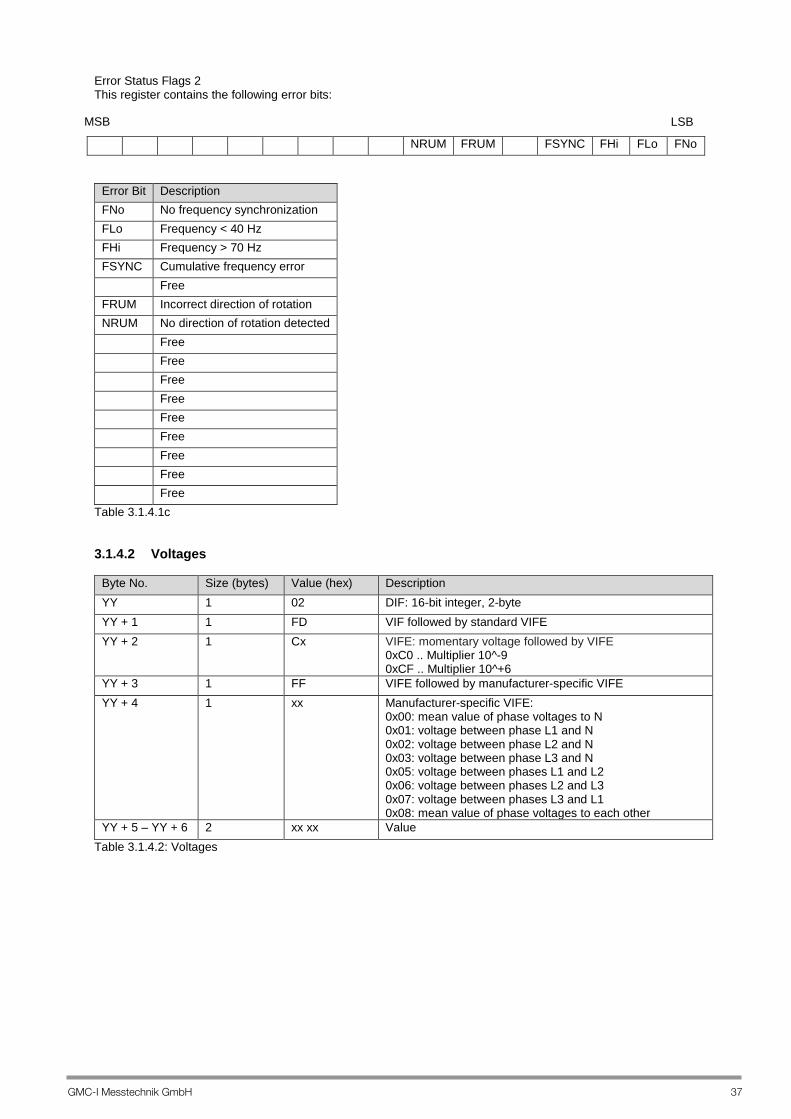
Error Status Flags 2 This register contains the following error bits:
Error Bit Description FNo No frequency synchronization FLo Frequency < 40 Hz FHi Frequency > 70 Hz FSYNC Cumulative frequency error Free FRUM Incorrect direction of rotation NRUM No direction of rotation detected Free Free Free Free Free Free Free Free Free
Table 3.1.4.1c 3.1.4.2 Voltages
Byte No. Size (bytes) Value (hex) Description YY 1 02 DIF: 16-bit integer, 2-byte YY + 1 1 FD VIF followed by standard VIFE YY + 2 1 Cx VIFE: momentary voltage followed by VIFE
0xC0 .. Multiplier 10^-9 0xCF .. Multiplier 10^+6
YY + 3 1 FF VIFE followed by manufacturer-specific VIFE YY + 4 1 xx Manufacturer-specific VIFE:
0x00: mean value of phase voltages to N 0x01: voltage between phase L1 and N 0x02: voltage between phase L2 and N 0x03: voltage between phase L3 and N 0x05: voltage between phases L1 and L2 0x06: voltage between phases L2 and L3 0x07: voltage between phases L3 and L1 0x08: mean value of phase voltages to each other
YY + 5 – YY + 6 2 xx xx Value Table 3.1.4.2: Voltages
NRUM FRUM FSYNC FHi FLo FNo
MSB LSB
38 GMC-I Messtechnik GmbH
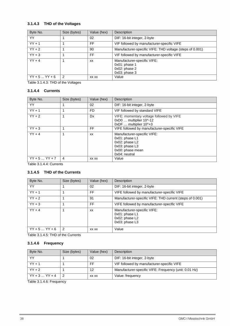
3.1.4.3 THD of the Voltages
Byte No. Size (bytes) Value (hex) Description YY 1 02 DIF: 16-bit integer, 2-byte YY + 1 1 FF VIF followed by manufacturer-specific VIFE YY + 2 1 90 Manufacturer-specific VIFE: THD voltage (steps of 0.001) YY + 3 1 FF VIF followed by manufacturer-specific VIFE YY + 4 1 xx Manufacturer-specific VIFE:
0x01: phase 1 0x02: phase 2 0x03: phase 3
YY + 5 ... YY + 6 2 xx xx Value Table 3.1.4.3: THD of the Voltages 3.1.4.4 Currents
Byte No. Size (bytes) Value (hex) Description YY 1 02 DIF: 16-bit integer, 2-byte YY + 1 1 FD VIF followed by standard VIFE YY + 2 1 Dx VIFE: momentary voltage followed by VIFE
0xD0 … multiplier 10^-12 0xDF … multiplier 10^+3
YY + 3 1 FF VIFE followed by manufacturer-specific VIFE YY + 4 1 xx Manufacturer-specific VIFE:
0x01: phase L1 0x02: phase L2 0x03: phase L3 0x00: phase mean 0x04: neutral
YY + 5 … YY + 7 4 xx xx Value Table 3.1.4.4: Currents 3.1.4.5 THD of the Currents
Byte No. Size (bytes) Value (hex) Description YY 1 02 DIF: 16-bit integer, 2-byte YY + 1 1 FF VIFE followed by manufacturer-specific VIFE YY + 2 1 91 Manufacturer-specific VIFE: THD current (steps of 0.001) YY + 3 1 FF VIFE followed by manufacturer-specific VIFE
YY + 4 1 xx Manufacturer-specific VIFE: 0x01: phase L1 0x02: phase L2 0x03: phase L3
YY + 5 … YY + 6 2 xx xx Value Table 3.1.4.5: THD of the Currents 3.1.4.6 Frequency
Byte No. Size (bytes) Value (hex) Description
YY 1 02 DIF: 16-bit integer, 2-byte YY + 1 1 FF VIF followed by manufacturer-specific VIFE YY + 2 1 12 Manufacturer-specific VIFE: Frequency (unit: 0.01 Hz) YY + 3 … YY + 4 2 xx xx Value: frequency
Table 3.1.4.6: Frequency

GMC-I Messtechnik GmbH 39
3.1.4.7 Power
Byte No. Size (bytes) Value (hex) Description YY 1 82 DIF: 16-bit integer, 2-byte, followed by DIFE YY + 1 1 xx First DIFE (see section 2.2.2.1) YY + 2 1 xx Second DIFE (see section 2.2.2.1) YY + 3 1 Ax VIF: power followed by VIFE
0xA8 … multiplier 10^-3 0xAF … multiplier 10^+4
YY + 4 1 FF VIFE followed by manufacturer-specific VIFE YY + 5 1 xx Manufacturer-specific VIFE:
0x01: phase L1 0x02: phase L2 0x03: phase L3 0x09: total
YY + 6 ... YY + 7 2 xx xx Value: power Table 3.1.4.7a: Power (multiplier ≤ 10^+4)
Byte No. Size (bytes) Value (hex) Description YY 1 82 DIF: 16-bit integer, 2-byte, followed by DIFE YY + 1 1 xx First DIFE (see section 2.2.2.1) YY + 2 1 xx Second DIFE (see section 2.2.2.1) YY + 3 1 FB Extended VIFE follows YY + 4 1 xx VIF: power followed by VIFE
0xA8 … multiplier 10^+5 0xA9 … multiplier 10^+6
YY + 5 1 FF VIFE followed by manufacturer-specific VIFE YY + 6 1 xx Manufacturer-specific VIFE:
0x01: phase L1 0x02: phase L2 0x03: phase L3 0x09: total
YY + 7 ... YY + 8 2 xx xx Value: power Table 3.1.4.7b: Power (multiplier > 10^+4) 3.1.4.8 Power Factor PF
Byte No. Size (bytes) Value (hex) Description
YY 1 02 DIF: 16-bit integer, 2-byte YY + 1 1 FF VIF followed by manufacturer-specific VIFE YY + 2 1 93 Manufacturer-specific VIFE: power factor PF (steps of 0.001) YY + 3 1 FF VIF followed by manufacturer-specific VIFE YY + 4 1 xx Manufacturer-specific VIFE:
0x01: phase L1 0x02: phase L2 0x03: phase L3 0x09: total
YY + 5 ... YY + 6 2 xx xx Value: power factor PF
Table 3.1.4.8: Power Factor PF
40 GMC-I Messtechnik GmbH
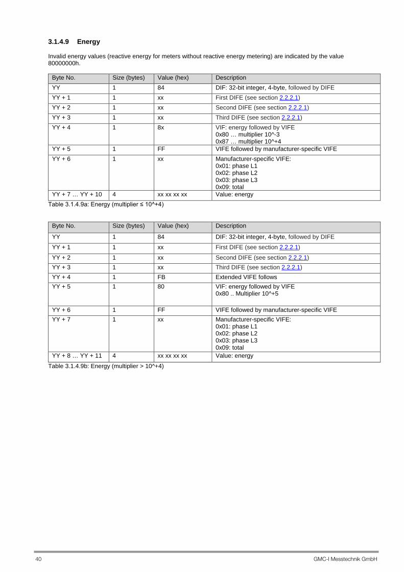
3.1.4.9 Energy Invalid energy values (reactive energy for meters without reactive energy metering) are indicated by the value 80000000h.
Byte No. Size (bytes) Value (hex) Description YY 1 84 DIF: 32-bit integer, 4-byte, followed by DIFE YY + 1 1 xx First DIFE (see section 2.2.2.1) YY + 2 1 xx Second DIFE (see section 2.2.2.1) YY + 3 1 xx Third DIFE (see section 2.2.2.1) YY + 4 1 8x VIF: energy followed by VIFE
0x80 … multiplier 10^-3 0x87 … multiplier 10^+4
YY + 5 1 FF VIFE followed by manufacturer-specific VIFE YY + 6 1 xx Manufacturer-specific VIFE:
0x01: phase L1 0x02: phase L2 0x03: phase L3 0x09: total
YY + 7 … YY + 10 4 xx xx xx xx Value: energy Table 3.1.4.9a: Energy (multiplier ≤ 10^+4)
Byte No. Size (bytes) Value (hex) Description
YY 1 84 DIF: 32-bit integer, 4-byte, followed by DIFE YY + 1 1 xx First DIFE (see section 2.2.2.1) YY + 2 1 xx Second DIFE (see section 2.2.2.1) YY + 3 1 xx Third DIFE (see section 2.2.2.1) YY + 4 1 FB Extended VIFE follows YY + 5 1 80 VIF: energy followed by VIFE
0x80 .. Multiplier 10^+5
YY + 6 1 FF VIFE followed by manufacturer-specific VIFE YY + 7 1 xx Manufacturer-specific VIFE:
0x01: phase L1 0x02: phase L2 0x03: phase L3 0x09: total
YY + 8 … YY + 11 4 xx xx xx xx Value: energy
Table 3.1.4.9b: Energy (multiplier > 10^+4)

GMC-I Messtechnik GmbH 41
3.1.4.10 Date and Time
Byte No. Size (bytes) Value (hex) Description
YY 1 06 DIF: data field = 0110b, type I
YY + 1 1 6D VIF: date and time YY + 2 ... YY + 7 6 xx xx xx xx xx xx Value: type I: date and time (CP48) (see table 3.1.4.10a)
Table 3.1.4.10: Date and Time Table 3.1.4.10a: Type I – Date and Time (CP48)
Byte/Bit MSBit LSBit LSByte 8 7 6 5 4 3 2 1 16 15 14 13 12 11 10 9 24 23 22 21 20 19 18 17 32 31 30 29 28 27 26 25 40 39 38 37 36 35 34 33 MSByte 48 47 46 45 44 43 42 41
Seconds UI6 [1 ... 6] < 0 ... 59 > Minutes UI6 [9 ... 14] < 0 ... 59 > Hours UI5 [17 ... 21] < 0 ... 23 Day UI5 [25 ... 29] < 1 ... 31 > Month UI4 [33 ... 36] < 1 ... 12 > Year UI7 [30 ... 32 + 37 ... 40] < 0 ... 99 > The other bits are zero. 3.1.4.11 Current Tariff
Byte No. Size (bytes) Value (hex) Description
YY 1 01 DIF: 8-bit integer, 1-byte YY + 1 1 FF VIF followed by manufacturer-specific VIFE YY + 2 1 14 Manufacturer-specific VIFE: current tariff YY + 3 1 xx Value: current tariff (0x01 - 0x08)
Table 3.1.4.11: Current Tariff 3.1.4.12 Current Transformer Ratio (CT)
Byte No. Size (bytes) Value (hex) Description
YY 1 02 DIF: 16-bit integer, 2-byte YY + 1 1 FF VIF followed by manufacturer-specific VIFE YY + 2 1 15 Manufacturer-specific VIFE: CT value YY + 3 … YY + 4 2 xx xx Value: CT value
Table 3.1.4.12 3.1.4.13 Voltage Transformer Ratio (VT)
Byte No. Size (bytes) Value (hex) Description
YY 1 02 DIF: 16-bit integer, 2-byte YY + 1 1 FF VIF followed by manufacturer-specific VIFE YY + 2 1 16 Manufacturer-specific VIFE: VT value YY + 3 ... YY + 4 2 xx xx Value: VT value
Table 3.1.4.13

42 GMC-I Messtechnik GmbH
3.1.4.14 Load Profile Integrating Period (with feature Z1 only)
Byte No. Size (bytes) Value (hex) Description
YY 1 01 DIF: 8-bit integer, 1-byte YY + 1 1 FF VIF followed by manufacturer-specific VIFE YY + 2 1 1A Manufacturer-specific VIFE: load profile integrating
period YY + 3 1 xx Value: load profile integrating period
Table 3.1.4.14: Load Profile Integrating Period (with feature Z1 only) 3.1.4.15 Features
Byte No. Size (bytes) Value (hex) Description
YY 1 0D DIF: variable length YY + 1 1 FF VIF followed by manufacturer-specific VIFE YY + 2 1 1B Manufacturer-specific VIFE: features YY + 3 1 40 LVAR = 64d YY + 4 ... YY + 67 64 xx-xx Features
Table 3.1.4.15: Features 3.1.4.16 Preset Date and Time of the Cutoff Date
Byte No. Size (bytes) Value (hex) Description
YY 1 06 DIF: data field = 0110b, type I
YY + 1 1 FF VIF followed by manufacturer-specific VIFE YY + 2 1 1C Manufacturer-specific VIFE: date and time of the cutoff
date YY + 3 ... YY + 8 6 xx xx xx xx xx xx Value: type I: date and time (CP48) (see table
3.1.4.10a) Table 3.1.4.16: Date and Time of the Cutoff Date 3.1.4.17 Preset Date and Time for Resetting the Resettable Meters
Byte No. Size (bytes) Value (hex) Description
YY 1 06 DIF: data field = 0110b, type I
YY + 1 1 FF VIF followed by manufacturer-specific VIFE YY + 2 1 19 Manufacturer-specific VIFE: preset reset time for
resettable meters YY + 3 … YY + 8 6 xx xx xx xx xx xx Value: type I: date and time (CP48) (see table
3.1.4.10a) Table 3.1.4.17: Preset Date and Time for Resetting the Resettable Meters 3.1.4.18 Time Stamp of the last Cutoff Date
Byte No. Size (bytes) Value (hex) Description
YY 1 06 DIF: data field = 0110b, type I
YY + 1 1 FF VIF followed by manufacturer-specific VIFE YY + 2 1 1E Manufacturer-specific VIFE: time stamp for resettable
meters YY + 3 ... YY + 8 6 xx xx xx xx xx xx Value: type I: date and time (CP48) (see table
3.1.4.10a) Table 3.1.4.18: Time Stamp of the last Cutoff Date
GMC-I Messtechnik GmbH 43
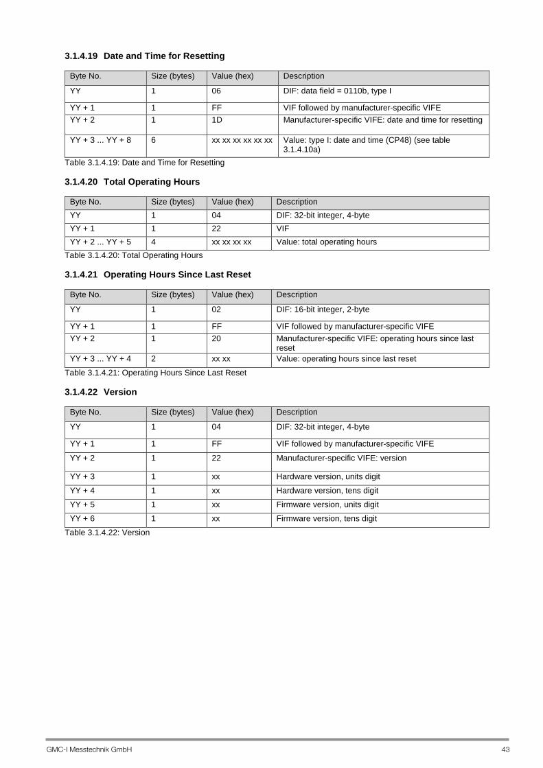
3.1.4.19 Date and Time for Resetting
Byte No. Size (bytes) Value (hex) Description
YY 1 06 DIF: data field = 0110b, type I
YY + 1 1 FF VIF followed by manufacturer-specific VIFE YY + 2 1 1D Manufacturer-specific VIFE: date and time for resetting
YY + 3 ... YY + 8 6 xx xx xx xx xx xx Value: type I: date and time (CP48) (see table 3.1.4.10a)
Table 3.1.4.19: Date and Time for Resetting 3.1.4.20 Total Operating Hours
Byte No. Size (bytes) Value (hex) Description YY 1 04 DIF: 32-bit integer, 4-byte YY + 1 1 22 VIF YY + 2 ... YY + 5 4 xx xx xx xx Value: total operating hours
Table 3.1.4.20: Total Operating Hours 3.1.4.21 Operating Hours Since Last Reset
Byte No. Size (bytes) Value (hex) Description
YY 1 02 DIF: 16-bit integer, 2-byte
YY + 1 1 FF VIF followed by manufacturer-specific VIFE YY + 2 1 20 Manufacturer-specific VIFE: operating hours since last
reset YY + 3 ... YY + 4 2 xx xx Value: operating hours since last reset
Table 3.1.4.21: Operating Hours Since Last Reset 3.1.4.22 Version
Byte No. Size (bytes) Value (hex) Description
YY 1 04 DIF: 32-bit integer, 4-byte
YY + 1 1 FF VIF followed by manufacturer-specific VIFE
YY + 2 1 22 Manufacturer-specific VIFE: version
YY + 3 1 xx Hardware version, units digit
YY + 4 1 xx Hardware version, tens digit
YY + 5 1 xx Firmware version, units digit YY + 6 1 xx Firmware version, tens digit
Table 3.1.4.22: Version
44 GMC-I Messtechnik GmbH
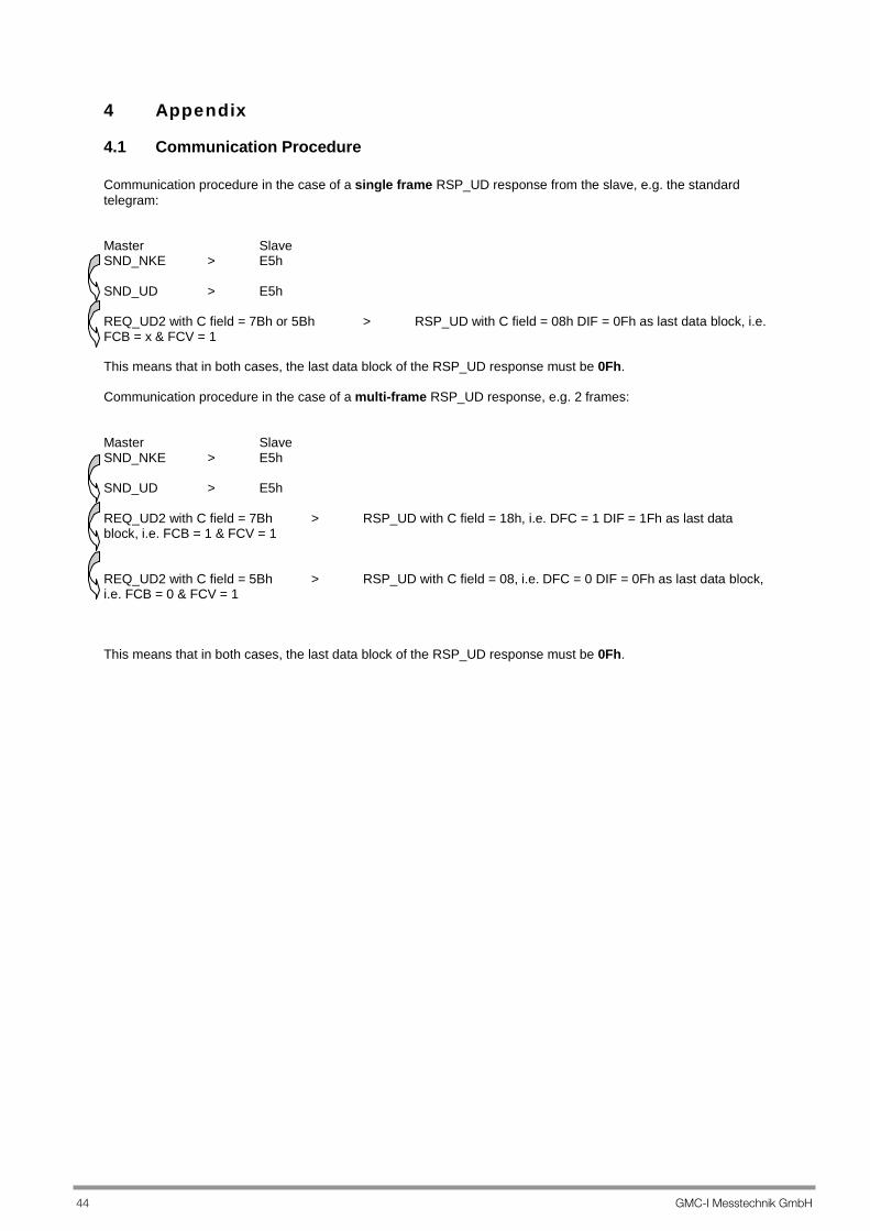
4 Appendix
4.1 Communication Procedure Communication procedure in the case of a single frame RSP_UD response from the slave, e.g. the standard telegram: Master Slave SND_NKE > E5h SND_UD > E5h REQ_UD2 with C field = 7Bh or 5Bh > RSP_UD with C field = 08h DIF = 0Fh as last data block, i.e. FCB = x & FCV = 1 This means that in both cases, the last data block of the RSP_UD response must be 0Fh. Communication procedure in the case of a multi-frame RSP_UD response, e.g. 2 frames: Master Slave SND_NKE > E5h SND_UD > E5h REQ_UD2 with C field = 7Bh > RSP_UD with C field = 18h, i.e. DFC = 1 DIF = 1Fh as last data block, i.e. FCB = 1 & FCV = 1 REQ_UD2 with C field = 5Bh > RSP_UD with C field = 08, i.e. DFC = 0 DIF = 0Fh as last data block, i.e. FCB = 0 & FCV = 1 This means that in both cases, the last data block of the RSP_UD response must be 0Fh.
GMC-I Messtechnik GmbH 45
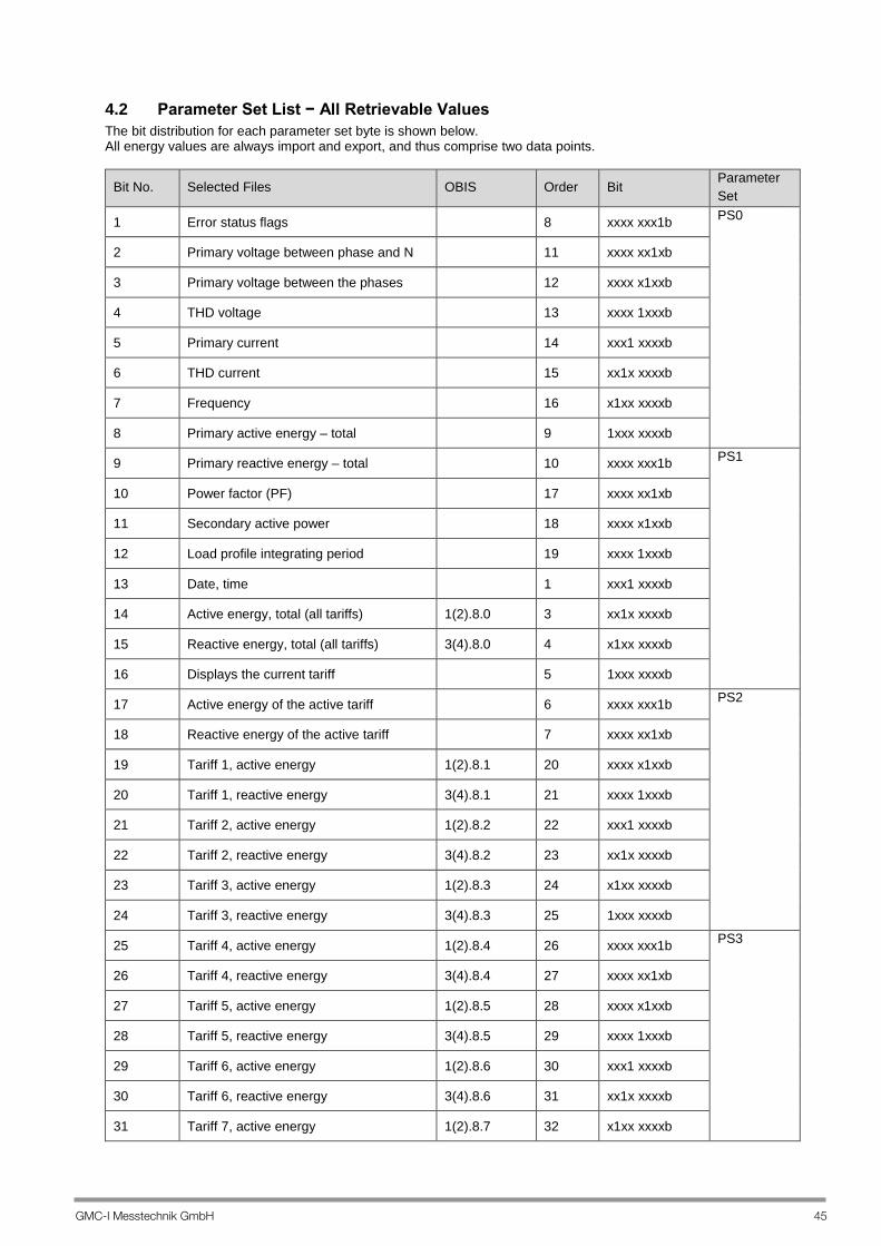
4.2 Parameter Set List − All Retrievable Values The bit distribution for each parameter set byte is shown below. All energy values are always import and export, and thus comprise two data points.
Bit No. Selected Files OBIS Order Bit Parameter Set
1 Error status flags 8 xxxx xxx1b PS0
2 Primary voltage between phase and N 11 xxxx xx1xb
3 Primary voltage between the phases 12 xxxx x1xxb
4 THD voltage 13 xxxx 1xxxb
5 Primary current 14 xxx1 xxxxb
6 THD current 15 xx1x xxxxb
7 Frequency 16 x1xx xxxxb
8 Primary active energy – total 9 1xxx xxxxb
9 Primary reactive energy – total 10 xxxx xxx1b PS1
10 Power factor (PF) 17 xxxx xx1xb
11 Secondary active power 18 xxxx x1xxb
12 Load profile integrating period 19 xxxx 1xxxb
13 Date, time 1 xxx1 xxxxb
14 Active energy, total (all tariffs) 1(2).8.0 3 xx1x xxxxb
15 Reactive energy, total (all tariffs) 3(4).8.0 4 x1xx xxxxb
16 Displays the current tariff 5 1xxx xxxxb
17 Active energy of the active tariff 6 xxxx xxx1b PS2
18 Reactive energy of the active tariff 7 xxxx xx1xb
19 Tariff 1, active energy 1(2).8.1 20 xxxx x1xxb
20 Tariff 1, reactive energy 3(4).8.1 21 xxxx 1xxxb
21 Tariff 2, active energy 1(2).8.2 22 xxx1 xxxxb
22 Tariff 2, reactive energy 3(4).8.2 23 xx1x xxxxb
23 Tariff 3, active energy 1(2).8.3 24 x1xx xxxxb
24 Tariff 3, reactive energy 3(4).8.3 25 1xxx xxxxb
25 Tariff 4, active energy 1(2).8.4 26 xxxx xxx1b PS3
26 Tariff 4, reactive energy 3(4).8.4 27 xxxx xx1xb
27 Tariff 5, active energy 1(2).8.5 28 xxxx x1xxb
28 Tariff 5, reactive energy 3(4).8.5 29 xxxx 1xxxb
29 Tariff 6, active energy 1(2).8.6 30 xxx1 xxxxb
30 Tariff 6, reactive energy 3(4).8.6 31 xx1x xxxxb
31 Tariff 7, active energy 1(2).8.7 32 x1xx xxxxb

46 GMC-I Messtechnik GmbH
Bit No. Selected Files OBIS Order Bit Parameter Set
32 Tariff 7, reactive energy 3(4).8.7 33 1xxx xxxxb
33 Tariff 8, active energy 1(2).8.8 34 xxxx xxx1b PS4
34 Tariff 8, reactive energy 3(4).8.8 35 xxxx xx1xb
35 Current transformer ratio (CT) 36 xxxx x1xxb
36 Voltage transformer ratio (VT) 37 xxxx 1xxxb
37 Resettable active energy from tariff 1 38 xxx1 xxxxb
38 Resettable reactive energy from tariff 1 39 xx1x xxxxb
39 Resettable active energy from tariff 2 40 x1xx xxxxb
40 Resettable reactive energy from tariff 2 41 1xxx xxxxb
41 Resettable active energy from tariff 3 42 xxxx xxx1b PS5
42 Resettable reactive energy from tariff 3 43 xxxx xx1xb
43 Resettable active energy from tariff 4 44 xxxx x1xxb
44 Resettable reactive energy from tariff 4 45 xxxx 1xxxb
45 Resettable active energy from tariff 5 46 xxx1 xxxxb
46 Resettable reactive energy from tariff 5 47 xx1x xxxxb
47 Resettable active energy from tariff 6 48 x1xx xxxxb
48 Resettable reactive energy from tariff 6 49 1xxx xxxxb
49 Resettable active energy from tariff 7 50 xxxx xxx1b PS6
50 Resettable reactive energy from tariff 7 51 xxxx xx1xb
51 Resettable active energy from tariff 8 52 xxxx x1xxb
52 Resettable reactive energy from tariff 8 53 xxxx 1xxxb
53 Active energy, tariff 1, on cutoff date 54 xxx1 xxxxb
54 Reactive energy, tariff 1, on cutoff date 55 xx1x xxxxb
55 Active energy, tariff 2, on cutoff date 56 x1xx xxxxb
56 Reactive energy, tariff 2, on cutoff date 57 1xxx xxxxb
57 Active energy, tariff 3, on cutoff date 58 xxxx xxx1b PS7
58 Reactive energy, tariff 3, on cutoff date 59 xxxx xx1xb
59 Active energy, tariff 4, on cutoff date 60 xxxx x1xxb
60 Reactive energy, tariff 4, on cutoff date 61 xxxx 1xxxb
61 Active energy, tariff 5, on cutoff date 62 xxx1 xxxxb
62 Reactive energy, tariff 5, on cutoff date 63 xx1x xxxxb
63 Active energy, tariff 6, on cutoff date 64 x1xx xxxxb
64 Reactive energy, tariff 6, on cutoff date 65 1xxx xxxxb
65 Active energy, tariff 7, on cutoff date 66 xxxx xxx1b PS8
GMC-I Messtechnik GmbH 47
Eng
lish
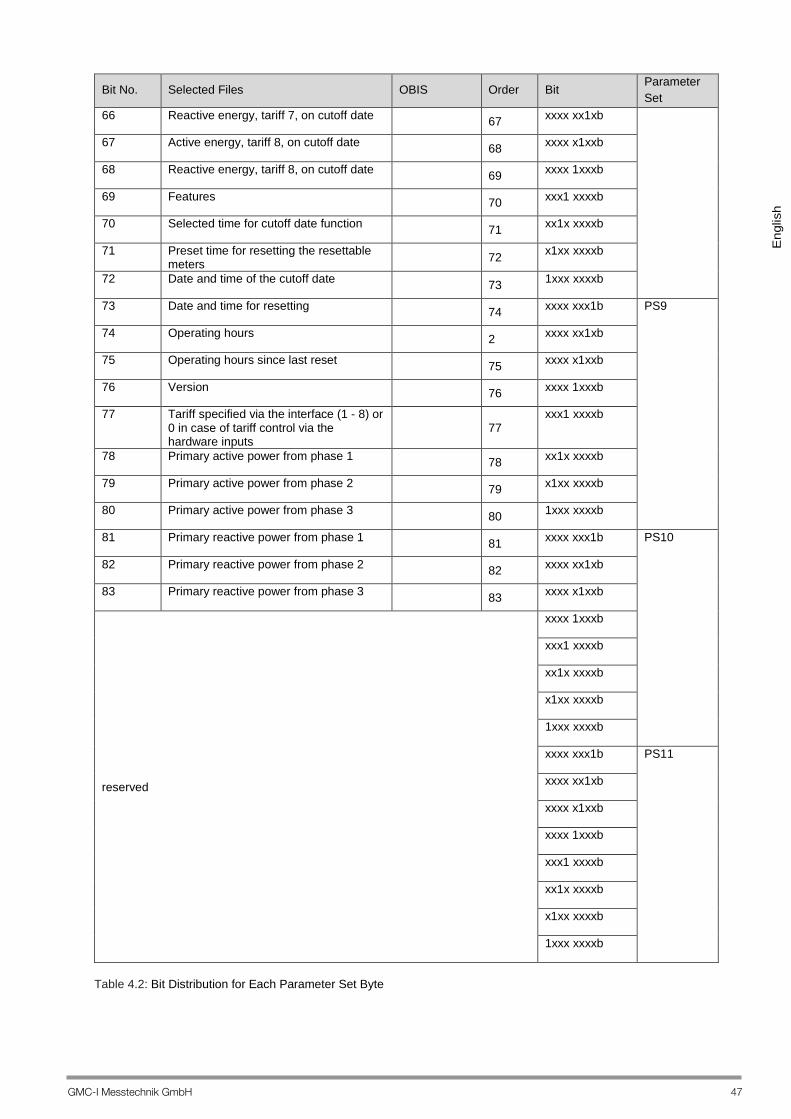
Bit No. Selected Files OBIS Order Bit Parameter Set
66 Reactive energy, tariff 7, on cutoff date 67 xxxx xx1xb
67 Active energy, tariff 8, on cutoff date 68 xxxx x1xxb
68 Reactive energy, tariff 8, on cutoff date 69 xxxx 1xxxb
69 Features 70 xxx1 xxxxb
70 Selected time for cutoff date function 71 xx1x xxxxb
71 Preset time for resetting the resettable meters
72 x1xx xxxxb
72 Date and time of the cutoff date 73 1xxx xxxxb
73 Date and time for resetting 74 xxxx xxx1b PS9
74 Operating hours 2 xxxx xx1xb
75 Operating hours since last reset 75 xxxx x1xxb
76 Version 76 xxxx 1xxxb
77 Tariff specified via the interface (1 - 8) or 0 in case of tariff control via the hardware inputs
77
xxx1 xxxxb
78 Primary active power from phase 1 78 xx1x xxxxb
79 Primary active power from phase 2 79 x1xx xxxxb
80 Primary active power from phase 3 80 1xxx xxxxb
81 Primary reactive power from phase 1 81 xxxx xxx1b PS10
82 Primary reactive power from phase 2 82 xxxx xx1xb
83 Primary reactive power from phase 3 83 xxxx x1xxb
reserved
xxxx 1xxxb
xxx1 xxxxb
xx1x xxxxb
x1xx xxxxb
1xxx xxxxb
xxxx xxx1b PS11
xxxx xx1xb
xxxx x1xxb
xxxx 1xxxb
xxx1 xxxxb
xx1x xxxxb
x1xx xxxxb
1xxx xxxxb
Table 4.2: Bit Distribution for Each Parameter Set Byte

48 GMC-I Messtechnik GmbH
4.3. Standard Telegram With up to and including M-Bus firmware version V1.10, a default parameters set is initiated for all phases, which follows its own sequence, when the meter is started up or after a power failure or an undervoltage event. This corresponds to the default status upon shipment for meters with M-Bus firmware as of version 1.15. This results in the following standard telegram: ParameterSet[1] xxx1 xxxxb date, time ParameterSet[9] xxxx xx1xb total operating hours ParameterSet[1] xx1x xxxxb total primary active energy (all tariffs), import total primary active energy (all tariffs), export ParameterSet[1] x1xx xxxxb total primary reactive energy (all tariffs), import
total primary reactive energy (all tariffs), export ParameterSet[1] 1xxx xxxxb active tariff ParameterSet[0] xxxx xxx1b error status flags ParameterSet[0] 1xxx xxxxb primary active power (sum of all phases) ParameterSet[1] xxxx xxx1b primary reactive power (sum of all phases) In this case single frame communication is involved and all values are transmitted in a single block: each new query results in current values. Refer to section 5.4. Set Telegram, in order to set up your own frame.

GMC-I Messtechnik GmbH 49
5 Application Notes Important Note: Only use ENERGYMID tool versions V1.17 or higher for meters with M bus firmware from V1.15 onwards.
5.1 Operating Logbook and Load Profile (feature Z1) The operating logbook and the load profile are read out sequentially from the latest to the oldest entry. The procedure is as follows:
– First of all, the last entry is read. – The next older entry is repeatedly retrieved thereafter. – In the event of transmission problems etc., it’s possible re-access previously read values.
Contents of the operating logbook:
– Events are logged with time stamp. – Event are logged once again when they disappear and their disappearance is indicated. – Parameter: Relevant parameters are also logged depending on the event.
Load profile functions (feature Z1):
– At the end of each integrating period, all 4 energy values fir the current tariff are saved to memory with enhanced accuracy along with time stamp and status.
– The calibratable energy values are always saved, and thus must be taken into consideration in the evaluation in the case of meters with adjustable CT/VT values.
– The integrating period is always ended synchronous to clock time, unless an event causes switching to a new period (e.g. tariff change, time change).
– The status represents a cumulative view of events which have occurred during the integrating period. – Incomplete integrating periods are identified. – In the case of a tariff change or a time change, the integrating period is interrupted, the value is stored
along with the old tariff or time and a new period is started.
5.2 Cutoff Date Meter The point in time at which the meter readings will be “frozen” can be preselected by setting date and time for the cutoff date function (see section 3.1.2.11), i.e. the current energy value status is copied to a separate data range and can be read out later (cutoff date energy values). It’s also still possible to retrieve the point in time of the last cutoff date (see section 3.1.4.18). Cutoff date energy values for tariffs 1 through 8 can be retrieved with the help of the parameter set list (see section 4.2). The following rules apply to the specification of a cutoff date:
- Point in time in the future: cutoff date energy values are updated at this point in time. - Point in time in the past: no updating of cutoff date energy values. - Current date, time of day in the past: current device time and cutoff date energy values are saved to
memory. - An entry of 0 to day, month or year functions as a placeholder: the cutoff date energy values are updated
on each corresponding date. - Everything in date and time set to 0 (placeholder): cutoff date via device clock, every day at midnight,
initial recording immediately.
5.3 Resettable Meter Similar to the cutoff date meter, meter readings are saved and the respective differential value (= current value - value at the time of resetting) is determined. The date and time at which the meter readings will be reset can be preselected by setting the reset time (see section. 3.1.2.10). Date and time of the completed reset operation can be read out in accordance with table 3.1.4.19. The energy readings for tariffs 1 through 8 of the resettable meter can be retrieved with the help of the parameter set list (see section 4.2). The following rules apply to the specification of a reset time point:
- Point in time in the future: reset at this point in time. - Point in time in the past: no resetting of energy values. - Current date, time of day in the past: immediate reset with current device clock time. - An entry of 0 to day, month or year functions as a placeholder: the energy values are reset on each
corresponding date. - Everything in date and time set to 0 (placeholder): reset via device clock, every day at midnight, initial
reset immediately.

50 GMC-I Messtechnik GmbH
5.4. Set Telegram Comment on versions: as from version V1.15, the last protocol setting is preserved in the event of a voltage failure. The parameter configuration of the protocol can be set via the PS field. Setting can be done either via command (Section 3.1.2.14 Setting Parameter Masks) or by means of the ENERGYMID tool (version V1.17). Example: Command for the configuration of the standard telegram: With this command you can configure via address 01 68 13 13 68 73 01 51 0D FD 0B 0C 81 F1 00 00 00 00 00 00 00 02 00 00 5A 16 Device Setting – Command: PS Field – configure

GMC-I Messtechnik GmbH 51
5.5. ENERGYMID Tool Important note: Only use ENERGYMID tool versions V1.17 or higher for meters with M bus firmware from V1.15 onwards. The following new functions are available as from ENERGYMID tool version V1.17: 1) For energy meter (M bus) firmware up to V1.10, the ENERGYMID tool sends out a standard command (it resets the telegram to the standard telegram). 2) As from version V1.15, the ENERGYMID tool does not change the telegram format permanently, but only temporarily up to the next SND_NKE telegram. This telegram is sent upon “Cut connection”. 3) The communication can now be directly displayed in the tool via the button „Display connection“. 4) The telegram can now be configured in the menu field “Device Setting“ by means of the command “Set PS field”.
With the help of the tool the protocol can now be configured as desired. The protocol can be adjusted by ticking the desired parameters. The following figure shows the setting for the standard telegram. The settings can be saved in the PC with „Store“.
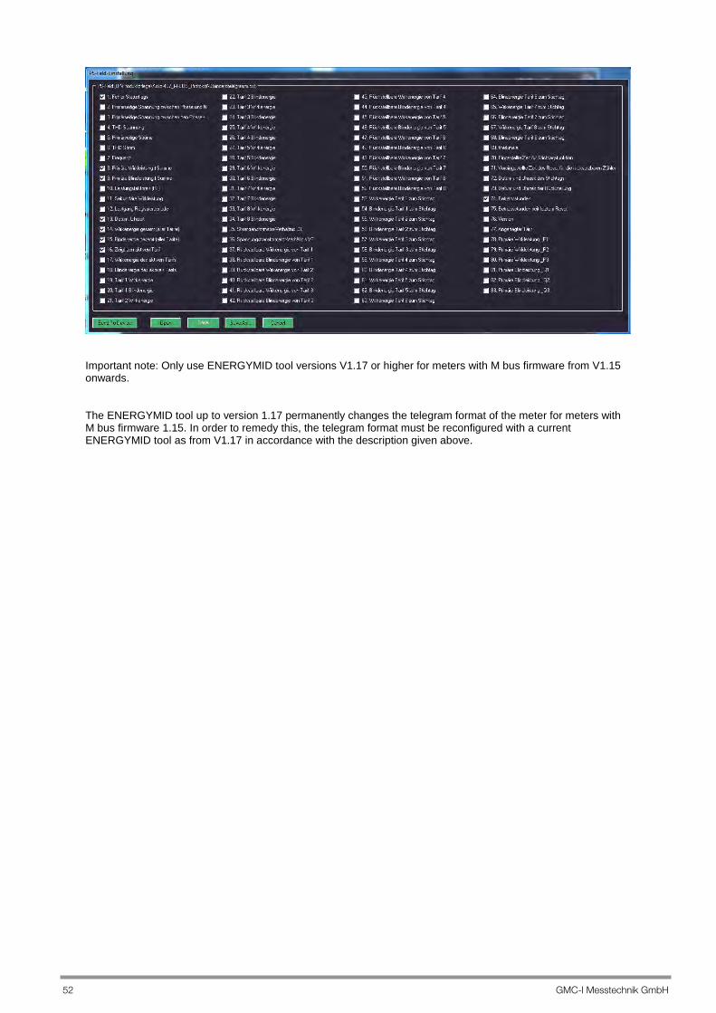
52 GMC-I Messtechnik GmbH
Important note: Only use ENERGYMID tool versions V1.17 or higher for meters with M bus firmware from V1.15 onwards. The ENERGYMID tool up to version 1.17 permanently changes the telegram format of the meter for meters with M bus firmware 1.15. In order to remedy this, the telegram format must be reconfigured with a current ENERGYMID tool as from V1.17 in accordance with the description given above.

GMC-I Messtechnik GmbH 53
6 Control and Display Functions Parameter Settings Overview (excerpt from operating instructions 3-349-868-03, supplement including M-Bus parameter settings)
Standard display
Change address Addres
Change baud rate
Change
Baud
Time/dat
long long

54 GMC-I Messtechnik GmbH
7 Product Support If required please contact:
GMC-I Messtechnik GmbH Industrial Product Support Hotline Phone: +49 911 8602-500 Fax: +49 911 8602-340 e-mail: [email protected]
Edited in Germany • Subject to change without notice • PDF version available on the Internet
Phone: +49 911 8602-111 GMC-I Messtechnik GmbH Fax +49 911 8602-777 Südwestpark 15 E-Mail [email protected] 90449 Nürnberg ● Germany www.gossenmetrawatt.com