Energy Scavenging for Automotive Sensors using Micro ... · Energy Scavenging for Automotive...
113
PROYECTO FIN DE CARRERA ENERGY SCAVENGING FOR AUTOMOTIVE SENSORS USING MICRO-ELECTRIC GENERATORS AUTOR: ARTURO AGUILERA FERNÁNDEZ MADRID, Junio 2009 UNIVERSIDAD PONTIFICIA COMILLAS ESCUELA TÉCNICA SUPERIOR DE INGENIERÍA (ICAI) INGENIERO INDUSTRIAL
Transcript of Energy Scavenging for Automotive Sensors using Micro ... · Energy Scavenging for Automotive...

PROYECTO FIN DE CARRERA
ENERGY SCAVENGING FOR
AUTOMOTIVE SENSORS USING
MICRO-ELECTRIC GENERATORS
AUTOR: ARTURO AGUILERA FERNÁNDEZ
MADRID, Junio 2009
UNIVERSIDAD PONTIFICIA COMILLAS
ESCUELA TÉCNICA SUPERIOR DE INGENIERÍA (ICAI)
INGENIERO INDUSTRIAL
Energy Scavenging for Automotive Sensors using Micro-Electric Generators
Executive Summary
PRODUCCIÓN DE ENERGÍA PARA SENSORES DEL
AUTOMOVIL USANDO GENERADORES MICRO-ELECTRICOS
Autor: Aguilera Fernández, Arturo.
Director: Anthony, Carl.
Entidad Colaboradora: University of Birmingham.
RESUMEN DEL PROYECTO
1. OBJETIVO DEL PROYECTO
- Investigar la generación energética a partir de fuentes cinéticas usando micro-
generadores.
- Emplear el reloj cinético como herramienta experimental para evaluar la
capacidad de generación energética.
2. MÉTODO EMPLEADO
- Determinación de la potencia requerida por los sistemas monitorizados de
control de presión de neumáticos (TPMS) y de las implicaciones de su
perfeccionamiento.
- Ingeniería inversa y experimentación del reloj cinético.
- Teorización del correspondiente generador rotacional electromagnético al
alimentar los sensores de presión inalámbricos.
- Modelado, simulación e implementación de los datos experimentales y teóricos
obtenidos.
- Miniaturización.
3. PRINCIPALES RESULTADOS
Energía renovable: Una mejora para TPMS.
El sistema TPMS directo resuelve los problemas de seguridad automovilística
causados por bajas presiones en los neumáticos. Importantes ventajas medio
ambientales y económicas se obtienen al sustituir la batería, que alimenta el
modulo de radio frecuencia del sensor con un mínimo de 2 mW, por un
dispositivo de generación y almacenamiento de energía libre de mantenimiento.
La fuente renovable más útil en el entorno del interior de un neumático es la

Energy Scavenging for Automotive Sensors using Micro-Electric Generators
Executive Summary
generación cinética electromagnética. En particular, la generación rotacional
aprovecha al máximo la inercia rotacional de la rueda y vence las limitaciones de
los generadores comunes lineales debidas a las restricciones del desplazamiento
interno.
El reloj cinético: Un dispositivo de transformación y almacenamiento de energía
rotacional electromagnética.
Los resultados experimentales sobre el reloj cinético revelan la tecnología de
conversión electromagnética de energía rotacional. El dispositivo transforma la
rotación del péndulo a través de la amplificación y transmisión del movimiento a
un rotor magnético que genera tensión en una bobina. Niveles de potencia
razonables se generan así gracias al desplazamiento angular relativo entre la masa
y la estructura. Esta generación irregular consigue la autonomía del sistema
cuando se acompaña de una batería recargable. Su implementación para alimentar
TPMS obliga a localizar el dispositivo cerca del sensor orientándolo
paralelamente al plano de rotación de la rueda.
Funcionamiento de esta fuente de potencia autosuficiente para sensores de
presión inalámbricos.
Su funcionamiento general recae en un movimiento oscilatorio de la masa
caracterizado por grandes amplitudes y altas frecuencias. Este patrón de
generación se localiza para velocidades constantes del vehículo superiores a 15
km/h, dónde la aceleración centrifuga es más de 10 veces superior a la aceleración
gravitacional. El máximo nivel de potencia alcanzado abarca desde 2 mW hasta
una generación saturada constante de 3 mW.
Por debajo de una velocidad constante del vehículo de 5 km/h, dónde el campo
gravitatorio es mayor que el campo centrífugo, el método de generación se acerca
a un generador convencional. Este funcionamiento reposa en la conversión de una
rotación continua gracias al movimiento estacionario absoluto de la masa causado
por la resistencia vertical de la gravedad. La potencia máxima generada en este
caso no excede los 2 mW. Entre ambos métodos, un comportamiento caótico
genera a su vez insuficientes niveles de potencia para TPMS.
Las mayores amplitudes se obtienen en un movimiento resonante oscilatorio que
puede ser establecido calibrando los valores de los parámetros para esta aplicación
Energy Scavenging for Automotive Sensors using Micro-Electric Generators
Executive Summary
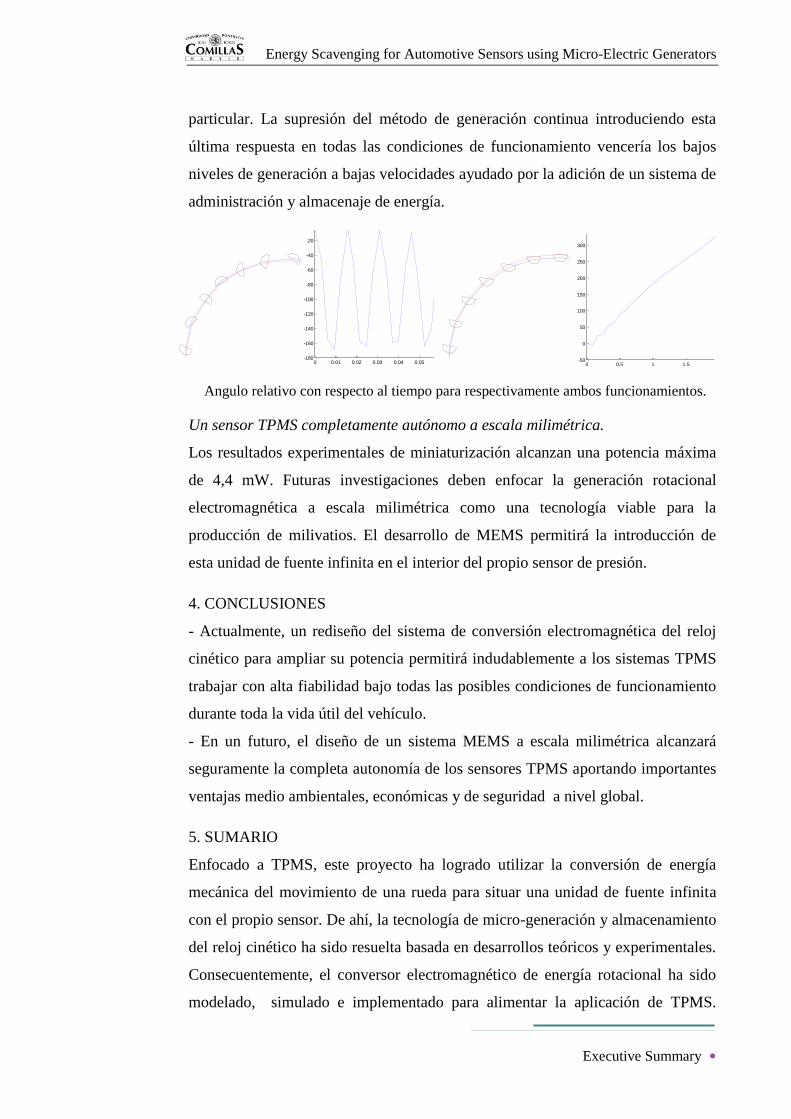
particular. La supresión del método de generación continua introduciendo esta
última respuesta en todas las condiciones de funcionamiento vencería los bajos
niveles de generación a bajas velocidades ayudado por la adición de un sistema de
administración y almacenaje de energía.
Un sensor TPMS completamente autónomo a escala milimétrica.
Los resultados experimentales de miniaturización alcanzan una potencia máxima
de 4,4 mW. Futuras investigaciones deben enfocar la generación rotacional
electromagnética a escala milimétrica como una tecnología viable para la
producción de milivatios. El desarrollo de MEMS permitirá la introducción de
esta unidad de fuente infinita en el interior del propio sensor de presión.
4. CONCLUSIONES
- Actualmente, un rediseño del sistema de conversión electromagnética del reloj
cinético para ampliar su potencia permitirá indudablemente a los sistemas TPMS
trabajar con alta fiabilidad bajo todas las posibles condiciones de funcionamiento
durante toda la vida útil del vehículo.
- En un futuro, el diseño de un sistema MEMS a escala milimétrica alcanzará
seguramente la completa autonomía de los sensores TPMS aportando importantes
ventajas medio ambientales, económicas y de seguridad a nivel global.
5. SUMARIO
Enfocado a TPMS, este proyecto ha logrado utilizar la conversión de energía
mecánica del movimiento de una rueda para situar una unidad de fuente infinita
con el propio sensor. De ahí, la tecnología de micro-generación y almacenamiento
del reloj cinético ha sido resuelta basada en desarrollos teóricos y experimentales.
Consecuentemente, el conversor electromagnético de energía rotacional ha sido
modelado, simulado e implementado para alimentar la aplicación de TPMS.
Angulo relativo con respecto al tiempo para respectivamente ambos funcionamientos.
0 0.01 0.02 0.03 0.04 0.05 0.06 0.07 0.08-180
-160
-140
-120
-100
-80
-60
-40
-20
0
Time (s)
Rela
tive a
ngle
(deg)
Relative Angular Position for Speed = 81 rad/s and Initial Condition = 0 degs
0 0.5 1 1.5 2 2.5-50
0
50
100
150
200
250
300
350
Time (s)
Rela
tive a
ngle
(deg)
Relative Angular Position for Speed = 3 rad/s and Initial Condition = 0 degs

Energy Scavenging for Automotive Sensors using Micro-Electric Generators
Executive Summary
Finalmente, se propone un diseño en miniatura. Los resultados finales alientan
futuros logros a corto plazo utilizando la energía renovable a través de
generadores micro-eléctricos para la industria automovilística.
ENERGY SCAVENGING FOR AUTOMOTIVE SENSORS USING
MICRO-ELECTRIC GENERATORS
1. AIMS
- Investigate energy harvesting from kinetic sources using micro-generators.
- Use kinetic wristwatch as an experimental tool for assessing energy generation
capability.
2. OBJECTIVES
- Determine power requirements of Direct TPMS, and implications of its
improvement.
- Reverse engineering and experimentation of kinetic wristwatch.
- Theorise on rotational electromagnetic generator powering wireless pressure
sensors.
- Modelling, simulation and implementation of experimental and theoretical data
obtained.
- Attempt miniaturisation.
3. MAIN RESULTS
Energy harvesting: A TPMS improvement.
Direct TPMS resolves automobile safety problems caused by low pressure tyres.
Important environmental and economic advantages are obtained from the
substitution of the battery, which powers a minimum of 2 mW to the sensor RF,
by a free-maintenance energy harvesting and storage device. The most advisable
renewable source in tyre environment is kinetic electromagnetic generation. In
particular, rotational generation makes the most of wheel rotational inertia and
overcomes common linear harvester limitations due to internal displacement
restrictions.

Energy Scavenging for Automotive Sensors using Micro-Electric Generators
Executive Summary
The kinetic watch: A rotational electromagnetic energy harvesting and storage
device.
Experimentation results of kinetic wristwatch reveal rotational electromagnetic
energy harvesting technology. The device damps its proof mass rotation by
amplifying and transmitting the motion to a magnetic rotor which generates
voltage into a coil. Reasonable power levels are then scavenged from the relative
angular movement between proof mass and frame. This irregular generation
achieves autonomy accompanied by a rechargeable battery. Its implementation to
power TPMS obliges to locate this device next to the sensor oriented parallel to
wheel rotational plane.
Operation of this self-renewable power source for wireless pressure sensors.
Its general operation relies on the oscillating motion of the proof mass
characterised by large amplitudes and high frequencies. This scavenging pattern
takes place for constant vehicle speeds above 15 km/h, where the centrifugal
acceleration is more than 10 times the gravitational acceleration. Maximum power
level achieved goes from 2 mW to a constant saturated generation of 3 mW.
Under a vehicle constant speed of 5 km/h, when the gravitational field is higher
than the centrifugal field, the harvesting method approaches a conventional
generator. This operation relies on scavenging continuous rotation due to the
absolute stationary motion of the proof mass caused by vertical opposition of
gravity. The maximum power generated in this case does not exceed 2 mW.
Between both methods, the chaotic motion generates as well insufficient power
levels for TPMS.
Relative angle position with respect to time for respectively both operations.
The largest amplitudes are obtained for oscillating resonant motion which can be
established redesigning parameter values for this particular application. The
elimination of continuous harvesting method, introducing that response at all
0 0.01 0.02 0.03 0.04 0.05 0.06 0.07 0.08-180
-160
-140
-120
-100
-80
-60
-40
-20
0
Time (s)
Rela
tive a
ngle
(deg)
Relative Angular Position for Speed = 81 rad/s and Initial Condition = 0 degs
0 0.5 1 1.5 2 2.5-50
0
50
100
150
200
250
300
350
Time (s)
Rela
tive a
ngle
(deg)
Relative Angular Position for Speed = 3 rad/s and Initial Condition = 0 degs

Energy Scavenging for Automotive Sensors using Micro-Electric Generators
Executive Summary
operating conditions will overcome poor generation at low speed, helped by the
addition of an energy management and storage system.
A millimetre-scaled complete autonomous TPMS sensor.
Experimental miniaturization results reach a maximum power of 4,4 mW. Future
researches have to focus on millimetre-scaled rotational electromagnetic
generation as a viable milliwatt powering technology. MEMS performance will
permit to introduce this infinite source unit into the pressure sensor itself.
4. CONCLUSIONS
- At present, a power scaled up design of kinetic watch inductive harvesting
system in its centimetre scale will definitely enable TPMS to work with high
reliability under all possible operating conditions during the vehicle entire life.
- A future MEMS design will surely achieve a millimetre-scaled complete
autonomous TPMS sensor which will contribute to important global
environmental, economic and safety advantages.
5. SUMMARY
Focusing on TPMS, this project has managed how to use mechanical energy
harvesting from wheel motion to place an infinite source unit with the sensor
itself. Thereby, kinetic wristwatch micro-generation and storage technology has
been solved based on theoretical developments and experimentation. Consequent
rotational electromagnetic energy harvester has been modelled, simulated and
implemented for powering TPMS application. Finally, a miniaturization design
has been approached. Final results encourage short term future achievements
using energy scavenging through micro-electric generators for the automotive
sensor industry.
Energy Scavenging for Automotive Sensors using Micro-Electric Generators
29/04/2009
Energy Scavenging for
Automotive Sensors using
Micro-Electric Generators BEng Engineering Project
School of Mechanical Engineering
Arturo Aguilera Fernández
Supervisor: Dr. Carl Anthony

Energy Scavenging for Automotive Sensors using Micro-Electric Generators
Acknowledgements
Acknowledgements
I would like to thank people who, in one way or another, have allowed this
engineering project to be completed. Thank you very much for your useful help
and support during current academic year.
First of all, many thanks to Dr. Carl Anthony who played a decisive role
throughout the development of this paper providing me with constant guidance
and assistance.
Secondly, special thanks to Mr. Alan Saywell for his collaboration during
the experimentation stage. Many thanks also to Dr. Mike Keeble for making
possible to back this work with high quality pictures. Likewise, I want to express
my gratitude to many other persons of the University of Birmingham who have
cooperated in experimental measurements lending me the instrumental equipment
needed.
Thirdly, my thanks go as well to David Cheneler for his collaboration
during the simulation stage, and to Imperial College of London for supplying a
PSpice energy harvesting simulator.
Finally, thanks to the technical support of UK Seiko for providing me with
really useful information.
Definitely, my most sincere gratitude goes to the University of
Birmingham for giving me the opportunity of living this research experience
abroad.
Energy Scavenging for Automotive Sensors using Micro-Electric Generators
Table of Contents
Table of Contents
INTRODUCTION 1
1. Aims of the project .............................................................................................. 2
2. Objectives of the project ...................................................................................... 3
3. Methods of research ............................................................................................. 4
CHAPTER I: Introduction to TPMS 5
1. Tyre pressure monitoring system......................................................................... 7
2. Safety implications of the project ........................................................................ 9
3. Commercial implications of the project .............................................................. 9
4. Environmental implications of the project ........................................................ 10
5. Conclusion of chapter I ...................................................................................... 11
CHAPTER II: Literature Review of Energy harvesting 12
1. Energy harvesting .............................................................................................. 13
2. Linear electromagnetic micro-generator............................................................ 16
3. Energy storage ................................................................................................... 23
4. Conclusion of chapter II .................................................................................... 24
CHAPTER III: The Kinetic Watch 25
1. Taking Seiko kinetic watch apart ...................................................................... 26
2. Seiko AGS properties ........................................................................................ 27
Energy Scavenging for Automotive Sensors using Micro-Electric Generators
Table of Contents
2.a. Oscillating weight ................................................................................. 28
2.b. Gear train .............................................................................................. 28
2.c. Generating rotor .................................................................................... 29
2.d. Generating coil...................................................................................... 31
2.e. Energy conversion interface ................................................................. 32
2.f. Step motor ............................................................................................. 38
3. Rotational electromagnetic micro-generator ..................................................... 41
3.a. Non resonant oscillating rotational generator ....................................... 41
3.b. Resonant oscillating rotational generator ............................................. 43
3.c. Continuous rotational generator ............................................................ 44
4. Conclusion of chapter III ................................................................................... 45
CHAPTER IV: Powering TPMS Sensors 46
1. Double pendulum............................................................................................... 47
2. Gravitational electromagnetic micro-generator ................................................. 49
3. Centrifugal electromagnetic micro-generator .................................................... 51
4. Conclusion of chapter IV ................................................................................... 59
CHAPTER V: Experimentation 60
1. Experimental starting ......................................................................................... 61
2. Experiment 1 ...................................................................................................... 63
3. Experiment 2 ...................................................................................................... 64
4. Conclusion of chapter V .................................................................................... 66
CHAPTER VI: Results 68

Energy Scavenging for Automotive Sensors using Micro-Electric Generators
Table of Contents
1. Electromagnetic circuit ...................................................................................... 69
2. Oscillating operation .......................................................................................... 70
3. Continuous operation ......................................................................................... 75
4. Conclusion of chapter VI ................................................................................... 78
CHAPTER VII: Miniaturisation 79
1. Scaling considerations ....................................................................................... 80
2. Design proposal ................................................................................................. 81
3. Conclusion of chapter VII ................................................................................. 83
CONCLUSIONS 84
REFERENCES 87
APPENDIX
Energy Scavenging for Automotive Sensors using Micro-Electric Generators
Table of Figures
Table of Figures
Figure 1: Tyre profile and wear on tread face. ........................................................ 6
Figure 2: Phaeton direct TPMS. .............................................................................. 7
Figure 3: Direct TPMS. ........................................................................................... 8
Figure 4: Phaeton pressure sensor package. ........................................................... 8
Figure 5: World automotive pressure sensors market. .......................................... 10
Figure 6: Energy harvesting and storage device. ................................................... 13
Figure 7: Main advantages and disadvantages of the three primary mechanical
energy converters. .................................................................................................. 14
Figure 8: Piezoelectric transducer. ........................................................................ 15
Figure 9: Electrostatic transducer. ......................................................................... 15
Figure 11: Lineal energy harvester. ....................................................................... 16
Figure 10: Faraday’s & Lenz’s laws. ..................................................................... 16
Figure 12: Vibrational harvester. ........................................................................... 17
Figure 13: Block diagram of a vibrational electromagnetic harvester. ................. 19
Figure 14: Damping effect. .................................................................................... 22
Figure 15: Power density of energy harvesting components ................................. 23
Figure 16: Pulsar kinetic watch. ............................................................................ 27
Figure 17: Electric circuit of Pulsar kinetic watch. ............................................... 28
Figure 18: Proof mass. ........................................................................................... 28
Figure 19: Gear train. ............................................................................................. 29
Figure 20: Rotor and stator. ................................................................................... 29
Figure 21: B-H curve of rare earth cobalt magnet. ................................................ 30
Figure 22: Coil block. ............................................................................................ 32
Figure 23: Rc measurement circuit. ....................................................................... 32
Figure 24: Battery. ................................................................................................. 33
Figure 25: Circuit block. ........................................................................................ 33
Figure 26: Simple model of a micro-generator...................................................... 34
Figure 27: Voltage output after signal through a full bridge diode rectifier. ........ 34
Energy Scavenging for Automotive Sensors using Micro-Electric Generators
Table of Figures
Figure 28: Additional capacitor to produce a DC voltage output. ......................... 35
Figure 29: Quartz unit. ........................................................................................... 37
Figure 30: Step motor. ........................................................................................... 39
Figure 31: Step motor. ........................................................................................... 40
Figure 32: Rotational harvester. ............................................................................ 41
Figure 33: Double pendulum. ................................................................................ 47
Figure 34: Rotating pendulum. .............................................................................. 51
Figure 35: Rotating pendulum with one plane of oscillation. ............................... 54
Figure 36: Rotating pendulum from reference ij. .................................................. 56
Figure 37: Rotating pendulum with gear train. ...................................................... 58
Figure 38: Marine mammal package. ................................................................... 61
Figure 39: Experimental assembly. ....................................................................... 62
Figure 40: Experimental device. ............................................................................ 62
Figure 42: Open-circuit generated voltage. ........................................................... 63
Figure 41: Voltage measurement circuit................................................................ 63
Figure 43: Generation measurement circuit. ......................................................... 64
Figure 44: Intensity generated. .............................................................................. 65
Figure 45: Voltage generated. ............................................................................... 65
Figure 46: Power generation. ................................................................................. 66
Figure 47: Natural frequency wn and wheel speed Ω with respect to vehicle
velocity. ................................................................................................................. 71
Figure 48: Rotor frequency wr regarding v............................................................ 71
Figure 49: Mass acceleration ϴr regarding v. ....................................................... 72
Figure 50: Mass restoring torque Tc regarding v. .................................................. 72
Figure 51: rΩ2/g ratio regarding v. ........................................................................ 73
Figure 52: Mass relative angle ϴr(t) for v= 6 km/h. .............................................. 74
Figure 53: Mass relative displacement ϴr for v= 60 km/h. ................................... 75
Figure 54: Mass relative displacement ϴr for v= 2 km/h. ..................................... 76
Figure 55: Power generated under v = 5 km/h. ..................................................... 77
Figure 56: Stator winding pattern. ......................................................................... 81
Figure 57: Power regarding rotor speed. ............................................................... 82
Figure 58: Miniaturisation proposal. ..................................................................... 83
Figure 59: Autonomous TPMS. ............................................................................. 83

Energy Scavenging for Automotive Sensors using Micro-Electric Generators
Table of Tables
Table of Tables
Table 1: Characteristics of rare earth cobalt. ......................................................... 30
Table 2: Magnetic circuit dimensions. .................................................................. 69
Table 3: Operational properties of the permanent magnet. ................................... 70
Table 4: Air gap results.......................................................................................... 70
Table 5: Parameter of wheel and oscillating weight. ............................................. 70

Energy Scavenging for Automotive Sensors using Micro-Electric Generators
1
INTRODUCTION

Energy Scavenging for Automotive Sensors using Micro-Electric Generators
Introduction 2
Introduction
These days, car manufacturers are at the forefront of developing
innovative sensing technologies due to high quantity of possible applications that
are present in the automotive industry. Moreover, vehicle environment represents
the most challenging conditions for micro-sensor systems. New sensor packages
are designed to obtain a competitive advantage or meet government regulations.
The subsequent customer acceptance involves trustworthiness and low cost.
Therefore, the output has to be stable during car lifetime, and the device has to be
small, as well as, easy to mount in its place. However, the current necessity of
wiring the sensor system back to vehicle power sources adds a significant higher
cost. Hence, this limitation has to be overcome by improving energy micro-
harvesting.
1. Aims of the project
This engineering project focuses specifically on tyre pressure monitoring
systems (TPMS). At the moment, their electricity supply is the vehicle
electrochemical battery or replaceable button cells. Therefore, this work is aimed
at using mechanical energy harvesting from wheel motion to place an infinite
source unit with the sensor itself. With last purpose, this project aims for solving
kinetic wristwatch micro-generation technology, and its electromagnetic energy
conversion and consequent storage. As a result, the design of a new autonomous
pressure sensor package will provide environmental, economic and technical
advantages.

Energy Scavenging for Automotive Sensors using Micro-Electric Generators
Introduction 3
2. Objectives of the project
Particular objectives of this engineering project are the followings.
Firstly, a research about tyres pressure and TPMS has to be done to deduce
commercial and environmental implications of the project, as well as, to
understand power requirements of this sensoring system.
Secondly, a literature review concerning energy harvesting and consequent
energy storage has to be made to discriminate between different energy generation
options. Subsequently, a model of a common linear electromagnetic generator will
be done to depict usual kinetic harvesters and approach electromagnetic energy
conversion.
Thirdly, a reverse engineering of a kinetic wristwatch will have to be done
with the purpose of understanding the running of this particular human rotational
energy harvesting device. Hence, a Seiko AGS system watch will be taken apart,
and later, specific researches, measurements and calculations will be done to
assess properties of different components. Furthermore, this rotational harvester
will be portrayed depending on the source of excitation and compared with the
previous linear model.
Fourthly, the studied rotational harvester will be analysed and described
mounted in its wheel application.
Fifthly, Seiko wristwatch will have to be tested to obtain data of its
harvesting generation capacity through experimentation. Consequently, using all
previous data and information, calculations will be made to discuss if this
commercial device is able to deliver the power required by a TPMS sensor. In
addition, software implementations of the device performance could help this
discussion.
Finally, preceding results will be used to try to achieve a miniaturized
design of a rotational electro-magnetic micro-harvester. Final conclusions will
then be expounded.

Energy Scavenging for Automotive Sensors using Micro-Electric Generators
Introduction 4
3. Methods of research
This project has required several methods of research to carry out the
work.
First of all, the introduction and literature review has been got from library
and online catalogue researches.
In addition, deduction of formulas to describe harvesting phenomena of
the kinetic wristwatch has been based on mechanical books and modern
periodicals, journals and university publications because of the topical subject
discussed in this paper. Those formulations are generally based on international
system of units otherwise it will be specifically pointed out. Miniaturization
design proposal is also based on up-to-date scientific and experimental
publications due to the nowadays lack of data, information and knowledge about
rotational electromagnetic micro/nano-generators.
Finally, measurements, models and experiments were carried out thanks to
cooperation and proposals of many personnel of the University of Birmingham,
who are mentioned in Acknowledgements, due to requirements of specific
knowledge, instrumentation and equipment.

Energy Scavenging for Automotive Sensors using Micro-Electric Generators
5
CHAPTER I
Introduction to TPMS

Energy Scavenging for Automotive Sensors using Micro-Electric Generators
Chapter I 6
Chapter I
Introduction to TPMS
Vehicle motion depends mainly on contact forces between tyre and road,
and consequently on tyre characteristics (Figure 1). Recommended tyre air
pressure, which is specified by the manufacturer, distributes the necessary load to
cause the correct amount of frictional force for enabling vehicle performance. As
studied, low pressure tyres induce poor handling, squealing, overheating,
premature tread wear, increasing self aligning torque, and steer problems.
Furthermore, low pressure increases braking distance, and traction is not
improved. In extreme cases, tread separation or even wheel rim detachment can
occur. So incorrectly inflated tyres give rise to safety, economic and
environmental problems.
Figure 1: Tyre profile and wear on tread face.
Moreover, in practice, a tyre can deflate up to half of its air pressure
without appearing it. Therefore, a system capable to manage low pressures
monitoring for alleviating those concerns would be hugely beneficial.
Energy Scavenging for Automotive Sensors using Micro-Electric Generators
Chapter I 7
1. Tyre pressure monitoring system
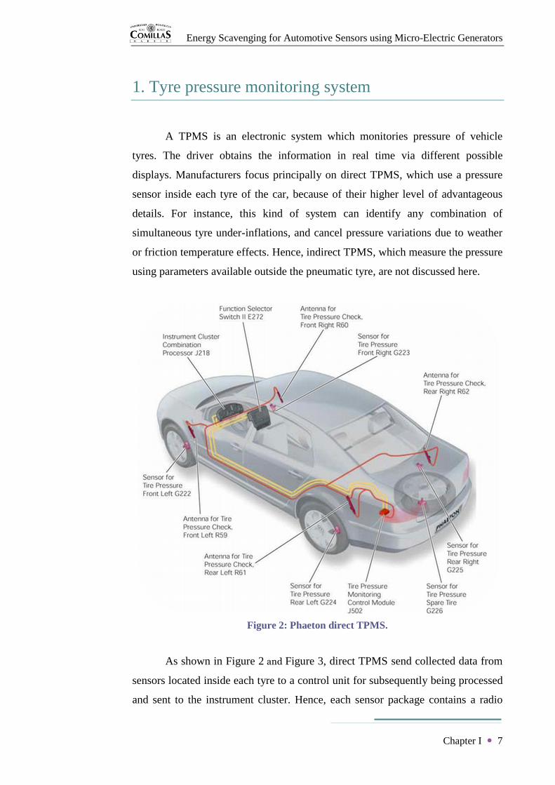
A TPMS is an electronic system which monitories pressure of vehicle
tyres. The driver obtains the information in real time via different possible
displays. Manufacturers focus principally on direct TPMS, which use a pressure
sensor inside each tyre of the car, because of their higher level of advantageous
details. For instance, this kind of system can identify any combination of
simultaneous tyre under-inflations, and cancel pressure variations due to weather
or friction temperature effects. Hence, indirect TPMS, which measure the pressure
using parameters available outside the pneumatic tyre, are not discussed here.
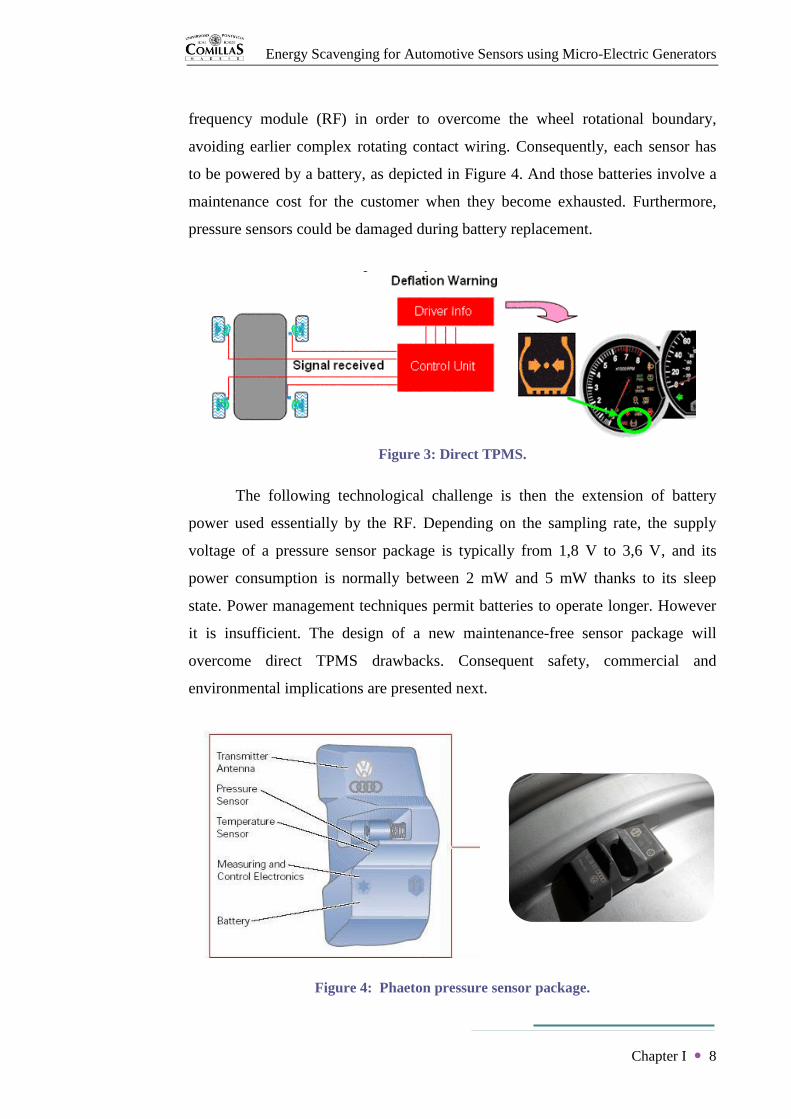
As shown in Figure 2 and Figure 3, direct TPMS send collected data from
sensors located inside each tyre to a control unit for subsequently being processed
and sent to the instrument cluster. Hence, each sensor package contains a radio
Figure 2: Phaeton direct TPMS.
Energy Scavenging for Automotive Sensors using Micro-Electric Generators
Chapter I 8
frequency module (RF) in order to overcome the wheel rotational boundary,
avoiding earlier complex rotating contact wiring. Consequently, each sensor has
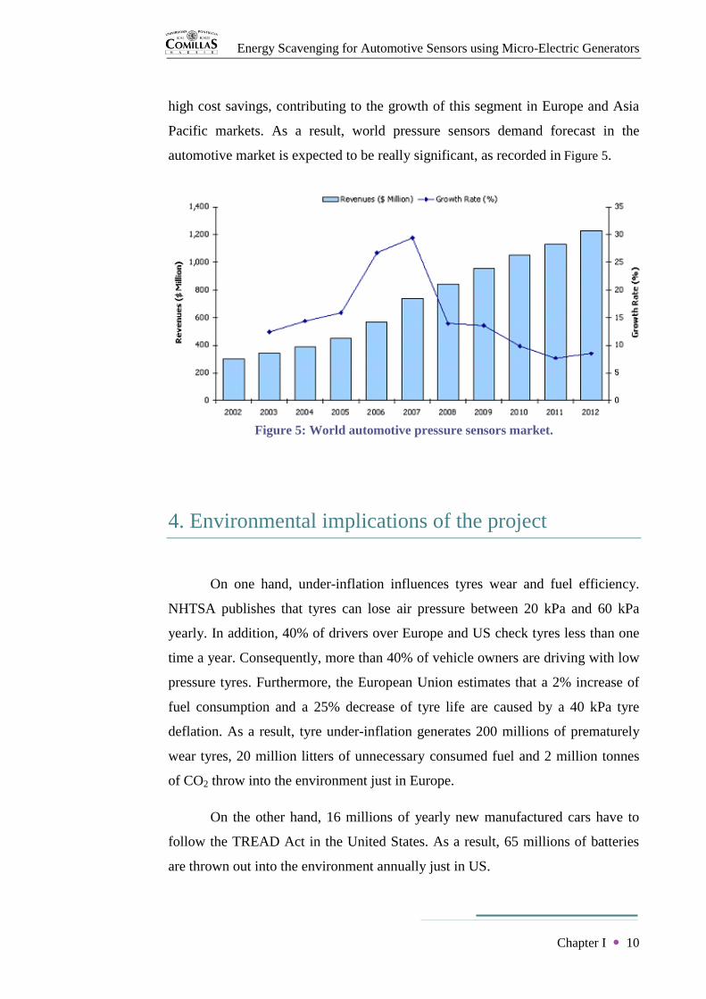
to be powered by a battery, as depicted in Figure 4. And those batteries involve a
maintenance cost for the customer when they become exhausted. Furthermore,
pressure sensors could be damaged during battery replacement.
Figure 3: Direct TPMS.
The following technological challenge is then the extension of battery
power used essentially by the RF. Depending on the sampling rate, the supply
voltage of a pressure sensor package is typically from 1,8 V to 3,6 V, and its
power consumption is normally between 2 mW and 5 mW thanks to its sleep
state. Power management techniques permit batteries to operate longer. However
it is insufficient. The design of a new maintenance-free sensor package will
overcome direct TPMS drawbacks. Consequent safety, commercial and
environmental implications are presented next.
Figure 4: Phaeton pressure sensor package.

Energy Scavenging for Automotive Sensors using Micro-Electric Generators
Chapter I 9
2. Safety implications of the project
In the United States, the National Highway Traffic Safety Administration
(NHTSA) announced that 533 deceases in road are linked to tyre problems in one
year; and if all vehicles would have had TPMS, 8400 injuries could have been
avoided and 120 fatalities would have been saved every year.
In Europe, the German DEKRA said that tyre irregularities are behind
41% of road injured accidents. The French road safety organization, Sécurité
Routière, made public that 9% of fatal accidents are caused by tyre under-
inflation.
Confirmed by statistics, tyre pressure condition is one of the most
important safety aspects of a vehicle, and therefore TPMS save lives. Hence, a
new generation of direct TPMS, which would not demand maintenance and would
be more reliable having a lower cost, will encourage car manufacturers and
customers to install this system in every vehicle as standard safety equipment.
3. Commercial implications of the project
In the United States, Clinton administration wrote the TREAD Act
because of the high number of deaths caused by accidents following a tyre tread
separation. After September 2007, all vehicles were required to install TPMS
which warn when the air pressure of a tyre decreases more than 25% of the
manufacturer recommendation. Frost & Sullivan divulged that $80,7 millions
were generated in US pressure sensor market in 2005. Thereafter, US revenues are
expected to increase at 30,7% until 2012, when they will be around $526,7
millions.
While in US direct TPMS development is based on safety legislation
reasons, Europe approaches TPMS from a more environmental point of view. A
new generation of direct TPMS would allow an international standardization and
Energy Scavenging for Automotive Sensors using Micro-Electric Generators
Chapter I 10
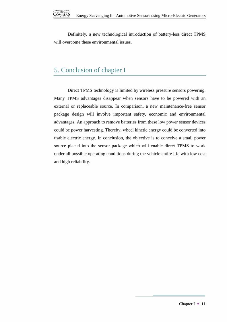
high cost savings, contributing to the growth of this segment in Europe and Asia
Pacific markets. As a result, world pressure sensors demand forecast in the
automotive market is expected to be really significant, as recorded in Figure 5.
Figure 5: World automotive pressure sensors market.
4. Environmental implications of the project
On one hand, under-inflation influences tyres wear and fuel efficiency.
NHTSA publishes that tyres can lose air pressure between 20 kPa and 60 kPa
yearly. In addition, 40% of drivers over Europe and US check tyres less than one
time a year. Consequently, more than 40% of vehicle owners are driving with low
pressure tyres. Furthermore, the European Union estimates that a 2% increase of
fuel consumption and a 25% decrease of tyre life are caused by a 40 kPa tyre
deflation. As a result, tyre under-inflation generates 200 millions of prematurely
wear tyres, 20 million litters of unnecessary consumed fuel and 2 million tonnes
of CO2 throw into the environment just in Europe.
On the other hand, 16 millions of yearly new manufactured cars have to
follow the TREAD Act in the United States. As a result, 65 millions of batteries
are thrown out into the environment annually just in US.
Energy Scavenging for Automotive Sensors using Micro-Electric Generators
Chapter I 11
Definitely, a new technological introduction of battery-less direct TPMS
will overcome these environmental issues.
5. Conclusion of chapter I
Direct TPMS technology is limited by wireless pressure sensors powering.
Many TPMS advantages disappear when sensors have to be powered with an
external or replaceable source. In comparison, a new maintenance-free sensor
package design will involve important safety, economic and environmental
advantages. An approach to remove batteries from these low power sensor devices
could be power harvesting. Thereby, wheel kinetic energy could be converted into
usable electric energy. In conclusion, the objective is to conceive a small power
source placed into the sensor package which will enable direct TPMS to work
under all possible operating conditions during the vehicle entire life with low cost
and high reliability.

Energy Scavenging for Automotive Sensors using Micro-Electric Generators
12
CHAPTER II
Literature Review of
Energy Harvesting

Energy Scavenging for Automotive Sensors using Micro-Electric Generators
Chapter II 13
Chapter II
Literature Review of Energy Harvesting
Limited accessibility of TPMS pressure sensors requires them to turn into
a completely autonomous micro-device. Energy harvesting motivation is exactly
to overcome environmental issues of throw-away batteries. Therefore, a
possibility to achieve a self-powered package is extracting energy from a self-
renewing environmental source. That challenging energy has to be converted and
stored because of its intermittent properties. Thereby, a harvesting generator will
be replenishing the consumption of the RF. Consequently, it is essential to
approach different harvesting methods to recognise the most suitable
environmental source of pressure sensors application conditions.
Figure 6: Energy harvesting and storage device.
1. Energy harvesting
Energy harvesting or scavenging is the conversion of environmental
energy into electrical energy. In other words, it is the process of ambient energy
capture and storage (Figure 6). This power technology is then an endless source
with non environmental effects. As quantified, pressure sensors require low power
and an energy harvesting micro-system is capable to scavenge milliwatts required.
However possible power densities depend on the specific application and
Energy Scavenging for Automotive Sensors using Micro-Electric Generators
Chapter II 14
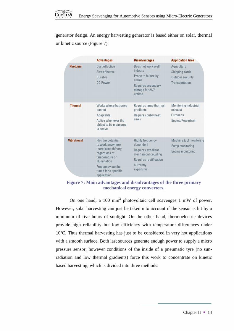
generator design. An energy harvesting generator is based either on solar, thermal
or kinetic source (Figure 7).
Figure 7: Main advantages and disadvantages of the three primary
mechanical energy converters.
On one hand, a 100 mm2 photovoltaic cell scavenges 1 mW of power.
However, solar harvesting can just be taken into account if the sensor is hit by a
minimum of five hours of sunlight. On the other hand, thermoelectric devices
provide high reliability but low efficiency with temperature differences under
10ºC. Thus thermal harvesting has just to be considered in very hot applications
with a smooth surface. Both last sources generate enough power to supply a micro
pressure sensor; however conditions of the inside of a pneumatic tyre (no sun-
radiation and low thermal gradients) force this work to concentrate on kinetic
based harvesting, which is divided into three methods.

Energy Scavenging for Automotive Sensors using Micro-Electric Generators
Chapter II 15
Figure 8: Piezoelectric transducer.
Kinetic energy harvesting converts the displacement of the transducer
device into electrical energy. Piezoelectric transducers produce a voltage drop
proportional to the piezoelectric material deformation or strain (Figure 8). And
electrostatic converters rely on the capacitance change of an initially charged
vibrational variable capacitor (Figure 9). However, properties of a wheel motion
demand this paper to focus on electromagnetic micro-generators because, even
though electromagnetic harvesting usually extracts the energy from vibration too,
it gives as well the possibility to scavenge kinetic energy from rotational motion.
Moreover, electromagnetic systems are more reliable working at large
accelerations. Electromagnetic micro-generation is then a promising method for
TPMS.
Figure 9: Electrostatic transducer.

Energy Scavenging for Automotive Sensors using Micro-Electric Generators
Chapter II 16
2. Linear electromagnetic micro-generator
Electromagnetic energy harvesting converts mechanical energy to a
current in a conductor via an electromagnetic field. Based on Faraday’s law, the
variation of a magnetic flux within a conductive circuit induces an electric
voltage. By Lenz’s law, this voltage polarity creates a current whose magnetic
field is opposite to the magnetic flux variation, trying always to keep the total
magnetic flux constant, as illustrates Figure 10.
Consequently, the electric generation relies on a relative movement
between a conductor and a magnet (Figure 11). The following analysis of a usual
vibration based electromagnetic generator refers to papers [CHIN00], [BEEB08]
and [GILB08].
Figure 11: Lineal energy harvester.
Typically, the model of a lineal energy harvesting device takes the form of
a spring, mass and damper system, as illustrated in Figure 12. A magnet of mass
m hangs from the device case, where a coil is fixed, through a spring of stiffness
k. A viscous damper of coefficient ct represents the parasitic losses cm and the
Figure 10: Faraday’s & Lenz’s laws.

Energy Scavenging for Automotive Sensors using Micro-Electric Generators
Chapter II 17
electrical energy extracted ce, since ct = cm + ce. y(t) is the position of the entire
device at time t, and z(t) is the relative position of the magnet referred to its
equilibrium position inside the device.
Figure 12: Vibrational harvester.
An input mechanical force fm(t) causes the vibration of the generator.
Hence, the magnet oscillates provoking its relative movement with regard to the
coil. The resulting variation of the magnetic flux linkage induces a voltage e(t)
and a current i(t) in the coil, getting the output power of the system. The
mechanical work is transformed into stored energy in the inductance L and into
heat in the resistance Rc when the coil is connected to a resistive load R.
Firstly, the magnet equation of motion is deduced from Newton’s second
law as
f t = mz t + cm z t + kz t (II. 1)
Hence the transfer function between the relative displacement z(t) and the total
force f(t) exerted on the magnet is
Z(s)
F(s)=
1
ms2 + cm s + k (II. 2)
Secondly, the induced voltage in the coil of N turns of side length l
moving at a velocity z t , which is supposed a sinusoidal of frequency ω, into a
magnetic flux of density B is
e t = NBlz t (II. 3)

Energy Scavenging for Automotive Sensors using Micro-Electric Generators
Chapter II 18
Therefore voltage of the load R is
v t = i t R =e t
R + Rc + jωLR
v(t) =NBlRz t
R + Rc + jωL (II. 4)
And using Laplace transform, the output voltage generated v(t) is linked to the
relative displacement z(t) by a first order system
V(s)
Z(s)=
NBlRs
R + Rc + Ls (II. 5)
Thirdly, the current i(t) induced in the coil causes an opposite
electromechanical force fe(t) which is defined by Lorentz force law as
fe t = NBli t (II. 6)
Hence the concept of electromagnetic constant is defined as
ke =e(t)
z (t)=
fe(t)
i(t)= NBl (II. 7)
Furthermore, the total force exerted on the magnet can be expressed as
f t = fm t − fe t = fm t − NBli t
f(t) = fm t −NBl
Rv t (II. 8)
As a result of equations (II.2), (II.5) and (II.8), the block diagram of Figure
13 presents the transfer function of the system which relates the output voltage
v(t) with the input force fm(t) as (II. 9)
V(s)
Fm (s)=
1ms2 + cm s + k
NBlRsR + Rc + Ls
1 +1
ms2 + cm s + kNBlRs
R + Rc + LsNBl
R
Energy Scavenging for Automotive Sensors using Micro-Electric Generators
Chapter II 19
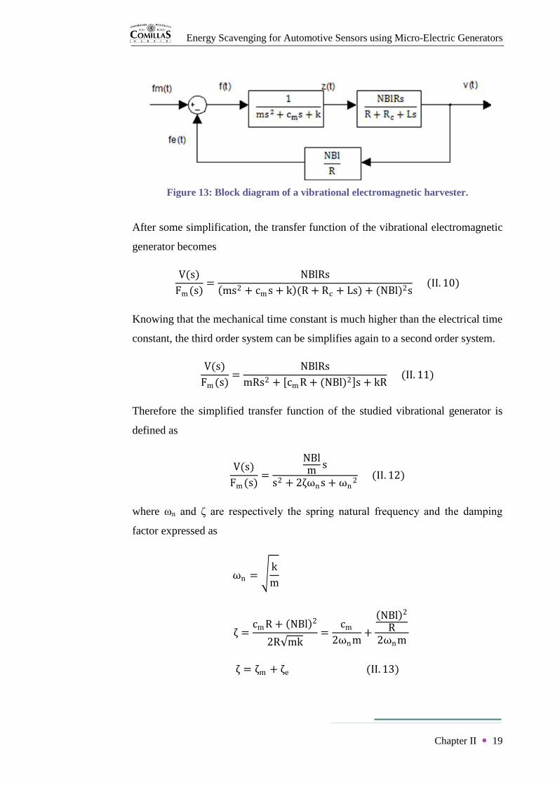
Figure 13: Block diagram of a vibrational electromagnetic harvester.
After some simplification, the transfer function of the vibrational electromagnetic
generator becomes
V(s)
Fm (s)=
NBlRs
ms2 + cm s + k (R + Rc + Ls) + (NBl)2s (II. 10)
Knowing that the mechanical time constant is much higher than the electrical time
constant, the third order system can be simplifies again to a second order system.
V(s)
Fm (s)=
NBlRs
mRs2 + cm R + (NBl)2 s + kR (II. 11)
Therefore the simplified transfer function of the studied vibrational generator is
defined as
V(s)
Fm (s)=
NBlm s
s2 + 2ζωns + ωn2
(II. 12)
where ωn and ζ are respectively the spring natural frequency and the damping
factor expressed as
ωn = k
m
ζ =cm R + NBl 2
2R mk=
cm
2ωnm+
NBl 2
R2ωnm
ζ = ζm + ζe (II. 13)

Energy Scavenging for Automotive Sensors using Micro-Electric Generators
Chapter II 20
knowing that ζm and ζe are respectively the mechanical and electrical damping
factors. Supposing that the conductor moves from the zero magnetic field to the
highest magnetic field B, the ideal electrical damping coefficient ce is
ce =(ke)2
R + Rc + jωL=
(NlB)2
R + Rc + jωL (II. 14)
Assuming an harmonic source of motion, the input displacement is a
sinusoidal y(t) = Y0 sin(ωt) whose maximum acceleration is y max = −Y0ω2.
The average input force becomes
Fm s = −mY s = −mY0
2ω2 (II. 15)
Hence, the corresponding output voltage is
V s =V s
Fm s Fm s
V s =
−Y0
2ω2NBls
s2 + 2ζωns + ωn2
(II. 16)
And knowing that s = jω,
V(jω) 2 =
Y02
2ω6 NBl 2
ωn2 − ω2 2 + 2ζωnω 2
=mY0
2 ωωn
3
ω3 (NBl)2
2ωnm
1 − ωωn
2
2
+ 2ζωωn
2
(II. 17)
Therefore, the average useful power generated by the linear electromagnetic
generator is
Pe = V 2
R=
mY02
ωωn
3
ω3ζe
1 − ωωn
2
2
+ 2ζωωn
2
(II. 18)

Energy Scavenging for Automotive Sensors using Micro-Electric Generators
Chapter II 21
The peak of output power occurs at resonance when ω = ωn. The expressions
become
Pe max =mY0
2ωn3ζ
e
4ζ2
VPe max = 2Pe max R =Y0ωnNBl
2ζ (II. 19)
The electromagnetic generator has then to be designed matching its natural
frequency with the vibration present on the environment of application. In
addition, the output voltage could be higher by increasing the coil and the magnet
mass m; however those are always limited by the size of the device case which is
determined by its specific application. Furthermore, the maximum power is
generated for ζp = ζe, obtaining
Pe max =mY0
2ωn3
16ζe (II. 20)
This maximum value can be achieved adjusting ce = cp using the optimum load R
given by
R = Rc +(NlB)2
cm (II. 21)
The total power dissipated on the harvesting system is
P =mY0
2 ωωn
3
ω3ζ
1 − ωωn
2
2
+ 2ζωωn
2
(II. 22)
Its maximum takes place also when the vibration frequency ω equals the resonant
frequency ωn.
P =mY0
2ωn3
4ζ (II. 23)

Energy Scavenging for Automotive Sensors using Micro-Electric Generators
Chapter II 22
Figure 14: Damping effect.
If the damping factor ζ increases, the power bandwidth increases as well, whereas
the peak effect decreases. Thus, a high damping factor should be used when the
source frequency changes, and on the contrary, the damping factor should be low
when the frequency of vibration is fixed. This reasoning is explained in Figure 14.
Finally, a solution for the relative displacement at steady state for the input
y(t) = Y0 sin(ωt) is
z t =Y0ω
2
km − ω2
2
+ ct
m ω 2
sin ωt + ϕ (II. 24)
where Φ is correspond to the phase angle as
ϕ = tan−1ctω
k − ω2m (II. 25)
The energy generated relies also on the frequency ω and amplitude Y0 related with
the mass displacement z; however the maximum displacement zmax is as well
limited by the size of the device.
Energy Scavenging for Automotive Sensors using Micro-Electric Generators
Chapter II 23
In conclusion, optimum operation of linear electromagnetic harvesters
depends highly on frequency and requires a resonant oscillating design. Whereas a
non resonant harvesting can be significantly more efficacious in cases with a wide
range of low frequencies and high amplitudes, its power density is lower. Power
levels of these devices are limited essentially by the oscillating mass m, the
maximum internal displacement zmax and the frequency ω and amplitude Y0 of the
source motion. As a result, the power density decreases with the device size and
the maximum generated power scales as linear dimension raised to the power of
four.
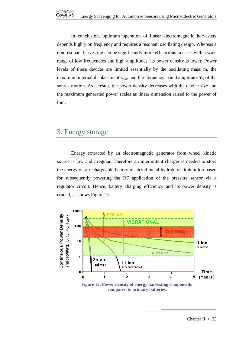
3. Energy storage
Energy extracted by an electromagnetic generator from wheel kinetic
source is low and irregular. Therefore an intermittent charger is needed to store
the energy on a rechargeable battery of nickel metal hydride or lithium ion based
for subsequently powering the RF application of the pressure sensor via a
regulator circuit. Hence, battery charging efficiency and its power density is
crucial, as shows Figure 15.
Figure 15: Power density of energy harvesting components
compared to primary batteries.
Energy Scavenging for Automotive Sensors using Micro-Electric Generators
Chapter II 24
As a result, wheel kinetic energy, which has normally been lost in the
environment, can now be harvested to power TPMS sensor packages extending
hugely their lifetime and overcoming primary battery disadvantages.
4. Conclusion of chapter II
Electromagnetic energy harvesting solution has been identified as the most
appropriate method for the particular environment of a tyre. An inductive micro-
generator and rechargeable battery system achieves TPMS sensors autonomy and
consequent independence from customer. However, power levels of common
kinetic energy harvesting devices are limited by internal displacement restrictions.
This limitation could be eliminated by damping instead the motion of a rotating
mass. Therefore, it is necessary to implement a rotational micro-generator using
the same previous principles to try to overcome power limitations of linear
harvesting and make the most of rotational kinetic energy of wheels. At the
moment, this technology is already used in some kinetic wristwatches.

Energy Scavenging for Automotive Sensors using Micro-Electric Generators
25
CHAPTER III
The Kinetic Wristwatch
Energy Scavenging for Automotive Sensors using Micro-Electric Generators
Chapter III 26
Chapter III
The Kinetic Wristwatch
In the mechanical field, the kinetic wristwatch has achieved to delete its
power maintenance employing human passive energy harvesting because of its
low power consumption. Thus the self-winding wristwatch is the precursor of
rotational power harvesting technology. The challenge is to do a reverse
engineering of the commercialized Seiko Automatic Generating System (AGS)
watch with the purpose of analysing the rotational micro-generator and
determining its power levels compared with previously detailed linear micro-
generator.
1. Taking Seiko kinetic watch apart
The first experimental approach to Seiko AGS technology involves taking
apart a Pulsar kinetic watch whose model is PAR087X1 and Cal. YT57. All
experimental works of this project will be using this device. The watch has then
been dismantled to understand how it works following precisely instructions of
catalogue [SEIK08]. The assembling instruction used and the resulting
chronological pictures, where the background white segments measure 1 cm, are
presented in Appendix 1. Consequently, the running mechanism and particularly
the rotational harvesting system of the watch were revealed. Therefore, the main
characteristics of Seiko kinetic wristwatch are described below.

Energy Scavenging for Automotive Sensors using Micro-Electric Generators
Chapter III 27
2. Seiko AGS properties
The studied wristwatch utilizes the motion of the arm to freely rotate a
semi-circular weight mounted off its center of mass on a ball bearing spindle.
Thus the oscillating proof mass winds the harvesting mechanism. A high ratio
transmission gear train attached to a generating permanent magnet rotor amplifies
the rotational movement. The high spinning speed of the rotor transforms the
inertial rotation into magnetic charges and induces an electric voltage and current
into the coil by means of a ferromagnetic stator circuit. Then the sinusoidal
generated power is rectified and stored in the energy storage unit. Subsequently,
the electrical energy required to run the quartz based hands system is supplied.
Figure 16 and Figure 17 show a comprehensive view of this wearable device.
Theoretically, the wristwatch generates on average 5 μW when it is worn, and
1 mW when is forcibly shaken. Each specific part is detailed next.
Figure 16: Pulsar kinetic watch.

Energy Scavenging for Automotive Sensors using Micro-Electric Generators
Chapter III 28
Figure 17: Electric circuit of Pulsar kinetic watch.
2.a. Oscillating weight
Parameters of the oscillating weight (Figure 18) were determined using a
digital scales and a calliper gauge. As a result, its radius and mass values are
respectively Rp = 13,5 mm and m = 4,8 g. Measurements were done 5 times and
the average of them was consider as the final reading. This method has been
carried out for all experimental measurements and tests of the project.
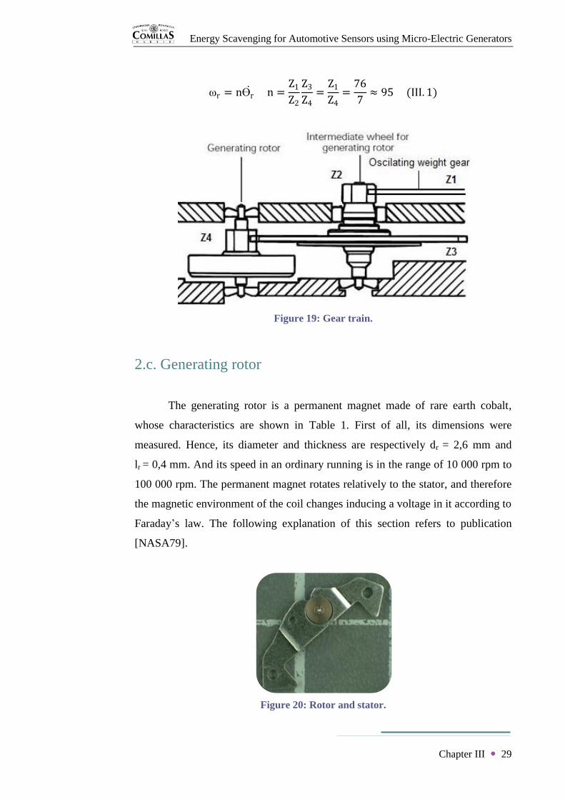
2.b. Gear train
The angular velocity of the generating rotor ωr is related to the relative
angular velocity of the oscillating weight ϴr by a gear ratio n of the transmission
train depicted in Figure 19. Knowing that the number of tooth of each gear is
Z1 = 76, Z2 = Z4 = 7 and Z3 = 61, the transmission ratio is defined by
Figure 18: Proof mass.
Energy Scavenging for Automotive Sensors using Micro-Electric Generators
Chapter III 29
ωr = nϴr n =
Z1
Z2
Z3
Z4=
Z1
Z4=
76
7≈ 95 (III. 1)
2.c. Generating rotor
The generating rotor is a permanent magnet made of rare earth cobalt,
whose characteristics are shown in Table 1. First of all, its dimensions were
measured. Hence, its diameter and thickness are respectively dr = 2,6 mm and
lr = 0,4 mm. And its speed in an ordinary running is in the range of 10 000 rpm to
100 000 rpm. The permanent magnet rotates relatively to the stator, and therefore
the magnetic environment of the coil changes inducing a voltage in it according to
Faraday’s law. The following explanation of this section refers to publication
[NASA79].
Figure 20: Rotor and stator.
Figure 19: Gear train.

Energy Scavenging for Automotive Sensors using Micro-Electric Generators
Chapter III 30
The excitation performance of the magnet and its operating properties rely
on the magnetic circuit installation (Figure 20). The type and size of permanent
magnet is established depending on magnetic requirements, mechanical design
and cost.
Table 1: Characteristics of rare earth cobalt.
The operating point of the magnet chosen is determined with the second
quadrant of the specific B-H curve for achieving a particular flux density in the air
gap. As shown in Figure 21, those graphs also draw curves of permeance ratio
Bm/Hm and energy product BmHm. The best energetic efficiency of a magnet takes
place when its operating conditions coincide with its maximum energy product,
which quantifies the magnetic energy that the permanent magnet supplies. In
addition, following equations are used to dimension the magnet and design the
magnetic circuit. CGS system of units have been used in this section for
simplification, since μ0 = 1 and Hg = Bg.
Figure 21: B-H curve of rare earth cobalt magnet.

Energy Scavenging for Automotive Sensors using Micro-Electric Generators
Chapter III 31
Designating Hm and Hg respectively for the magnetic field intensity of the
magnet and air gap (in oersted), lm and lg for respective lengths (in cm) and Vf for
the reluctance drop in the ferromagnetic circuit (in gilbert), Ampere’s law sets out
Hm lm = Hg lg + Vf (III. 2)
Furthermore, the cross sectional area of the magnet Am is related with the flux
density in the gap Bg by
Bm Am = BgAgK (III. 3)
where Bm is the flux density in the magnet (in gauss) and Ag the cross sectional
area of the air gap (in cm2). The leakage factor K quantifies the flux lost between
the side of the magnet and the beginning of the magnetic circuit. It is determined
by experimental formulas obtained for usual circuit configurations. In the case the
magnet is situated right next the air gap, the leakage factor is deduce from (III. 4)
K = 1 + 0,67pm
lg
Ag 1,7
0,335lm
0,335lm + lg+
lg
lm
where pm is the perimeter of the magnet cross section. From equations (III.2) and
(III.3) and neglecting Vf, the volume of the magnet is obtained with
Am lm =Bg
2Ag lgK
Bm Hm (III. 5)
Likewise, the permeance ratio expression is attained.
Bm
Hm=
Ag lm K
Am lg (III. 6)
2.d. Generating coil
The generating coil block (Figure 22), which measured side length is
l = 2 mm, is modelled as a voltage source, a resistor and an inductor in series.
Two experiments were carried out to determine the values of the equivalent
electric components. With this purpose, small cables had to be soldered to the

Energy Scavenging for Automotive Sensors using Micro-Electric Generators
Chapter III 32
terminals of the coil aided by a microscope. The result is shown in Appendix 2 as
well as next experimental electric assemblies.
On one hand, the first experiment consisted of the electrical assembly
illustrated in Figure 23. A voltmeter U and an ammeter A measure respectively
the voltage and current across the coil which are supplied by an intensity source I.
The resistor R1 = 99 kΩ is a protection against a possible high voltage across the
vulnerable micro-wire of the coil. The final readings were V = 33,6 mV and
I = 0,1 mA. Therefore the coil resistance is obtained.
Rc =V
I= 336 Ω (III. 7)
On the other hand, the coil was connected to a precision component
analyser that estimated a coil impedance of L = 191,4 mH.
2.e. Energy conversion interface
The electricity generated in the coil is rectified and stored in a titanium
lithium ion rechargeable battery (Figure 24) whose operating voltage range goes
Figure 23: Rc measurement circuit.
Figure 22: Coil block.

Energy Scavenging for Automotive Sensors using Micro-Electric Generators
Chapter III 33
from 0,45 V to 2,2 V. This storage unit is able to supply around 6 months of
energy from full charge to stoppage.
Subsequently, the circuit block (Figure 25) is in charge of the control of
voltage and amperage. Using quartz oscillations, it produces a precise electric
signal that is converted into a rotational motion by micro step motor. Finally a
gear train transmits this motion to move the hands and indicate the time. Hence,
the watch consumption is less than 1 μA with 1,55 V supplied from a battery.
Figure 25: Circuit block.
Figure 24: Battery.

Energy Scavenging for Automotive Sensors using Micro-Electric Generators
Chapter III 34
Rectification
In its very simplest form, an electromagnetic generator is modelled as an
AC voltage source as shown in Figure 26. However, this output is not useful for
most electronic applications. The generator is first connected to a full bridge
rectifier, which consists of four standard diodes connected in such a way that the
voltage reaching the load is always positive, as shown in the graph in Figure 27.
Figure 26: Simple model of a micro-generator.
Figure 27: Voltage output after signal through a full bridge diode rectifier.

Energy Scavenging for Automotive Sensors using Micro-Electric Generators
Chapter III 35
In the ideal-diode model, the device acts as a perfect conductor with no
voltage drop in the forward direction and acts as an open circuit in the reverse
direction. For a real diode, the output voltage is less than the input voltage due to
a drop across the diode, typically 0.7 V for silicon diodes at room temperature.
In order to provide a relatively stable voltage for electronics, a capacitor is
added to the output terminals of the bridge rectifier (Figure 28). If it is small
enough, the capacitor is charged up to the first peak of the voltage input. The
relationship between the current and voltage in a capacitor can be given by
i = Cdv(t)
dt
So the current is related to the change in voltage and the storage capacity of a
capacitor.
Once the input voltage drops below the voltage stored in the capacitor, the
capacitor slowly discharges until the next peak of the input. As a general rule, the
size of the capacitor required to smooth the voltage is
C =iT
2vr
where i is the average load current, T is the period of the bridge input voltage, and
vr is the peak-to-peak ripple voltage.
Figure 28: Additional capacitor to produce a DC voltage output.

Energy Scavenging for Automotive Sensors using Micro-Electric Generators
Chapter III 36
The size of the capacitor is typically sized to supply DC to the load.
However, because the current that can be delivered from the generator is very
small, the charge must first be built up on a capacitor or stored in a rechargeable
battery before it can be used.
Current portable electronic devices have different low power or sleep
modes to save energy during times of inactivity. The management of these modes
is very important in relation with an energy harvesting strategy, allowing to refill
the energy reservoir of the system during these periods of low activity. This
means that generally, a discontinuous operation use model is mandatory for the
energy harvesting approach.
Quartz unit
The amplitude of oscillation of a quartz resonator is of the order of a
thousandth of a millimetre. In addition the frequency of oscillation is normally
greater than 10 000 Hz. In our case of study, the oscillator oscillates at a highly
stable rate of 32 768 times per second. This is because the frequency is a function
of the elastic properties of quartz and the size of the crystal used, the frequency
decreasing as the size increases. The maximum size of available good-quality
crystals limits the lower frequency that can be obtained to the value quoted. It is
obvious therefore that mechanical methods cannot be used to detect or maintain
the vibrations of quartz. However, in addition to other useful properties, quartz is
piezoelectric, which enables these functions to be performed electronically.
The direct piezoelectric effect is the generation of electric charge on the
surface of some crystalline materials when they are strained mechanically. The
inverse piezoelectric effect takes place when a crystal is strained as a result of
applying to it an electric field. Piezoelectric materials are not uncommon, but
quartz combines the effect with good chemical and mechanical stability, and with
very low internal frictional losses, and it is therefore ideally suited for use as an
oscillator.
An important fact about both the direct and inverse effects is that they are
linear. This means that the effect is proportional to the cause: in the direct effect,

Energy Scavenging for Automotive Sensors using Micro-Electric Generators
Chapter III 37
the magnitude of the charge generated is proportional to the strain; in the inverse
effect, the strain is proportional to the field.
If a piece of quartz is set into vibration it is undergoing a mechanical strain
which is varying sinusoidally at the frequency of vibration. As a result of the
direct piezoelectric effect, electric charge is generated at the crystal surfaces, also
varying sinusoidally at the same frequency. If two metal electrodes are deposited
on the surfaces, the charges induce a voltage between them which is proportional
to the charge. The voltages can be detected by electronic means. Vibrations of
quartz can therefore be detected by means of the direct effect.
The inverse piezoelectric effect affords a means of maintaining the crystal
in oscillation. Two metal electrodes are deposited on the crystal surfaces. A
voltage applied between these sets up a field in the crystal, deforming it. If the
voltage between the electrodes varies at the frequency of oscillation of the crystal,
and if the position of the electrodes is chosen in such a way that the deformation
set up by the field is of the same form as that in the vibration, then energy is fed
into the oscillations to overcome frictional loss.
Figure 29: Quartz unit.
The basic electronically maintained quartz crystal controlled oscillator is
shown diagrammatically in Figure 29. A piece of quartz crystal with a natural
resonant frequency at the required oscillation frequency has two pairs of metal
electrodes deposited on its surfaces. The direct piezoelectric effect induces

Energy Scavenging for Automotive Sensors using Micro-Electric Generators
Chapter III 38
voltages between one pair which are connected to the input of an electronic
amplifier of gain A. The output voltage from the amplifier is fed to the second
pair of electrodes, and maintains the oscillations by the inverse piezoelectric
effect. The gain A of the amplifier is independent of frequency, and the gain β of
the quartz crystal, which is actually considerably less than unity, exhibits a sharp
resonance peak. So the product Aβ exhibits a similar peak and exceeds unity only
over a very narrow frequency range. The use of more sophisticated electronics
makes it possible to dispense with one pair of electrodes.
The quartz controlled oscillator is usually spoken of as an electronic
oscillator. It is perhaps as well to point out that it is really still a mechanical
oscillator, depending on the vibrations of a small piece of quartz, and is merely
electronically maintained.
2.f. Step motor
The step motor converts the electrical signal in to a precise rotational
motion that is transmitted to the hands through the gear train. Current
consumption of this tiny motors is 0,8 μA with a resistance between 1,7 kΩ and
2,1 kΩ.
The frequency divider accepts the signal generated by the quartz oscillator
and reduces its frequency to about 1 Hz to drive the display. It consists essentially
of a long chain of fairly simple circuits called bistables, each of which reduces the
frequency by a factor of five.
The main advance in this part of the watch has been the steady reduction in
its power consumption, which allows the use of higher quartz frequencies and
gives longer battery life. The introduction of a form of integrated circuit
construction called CMOJ; gave the most dramatic improvements here.
Focusing on the analogue display, the method of driving the seconds hand
is important. It is always by means of a small electric motor driven by the output
of the frequency division chain.
Energy Scavenging for Automotive Sensors using Micro-Electric Generators
Chapter III 39
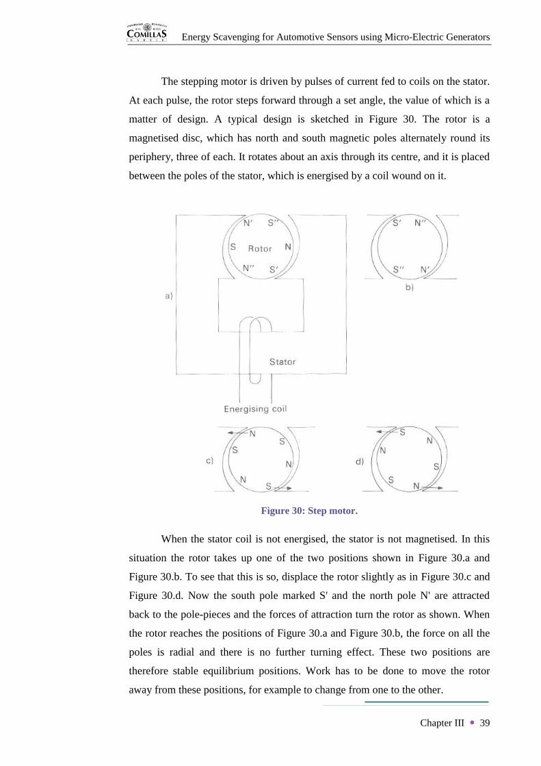
The stepping motor is driven by pulses of current fed to coils on the stator.
At each pulse, the rotor steps forward through a set angle, the value of which is a
matter of design. A typical design is sketched in Figure 30. The rotor is a
magnetised disc, which has north and south magnetic poles alternately round its
periphery, three of each. It rotates about an axis through its centre, and it is placed
between the poles of the stator, which is energised by a coil wound on it.
Figure 30: Step motor.
When the stator coil is not energised, the stator is not magnetised. In this
situation the rotor takes up one of the two positions shown in Figure 30.a and
Figure 30.b. To see that this is so, displace the rotor slightly as in Figure 30.c and
Figure 30.d. Now the south pole marked S' and the north pole N' are attracted
back to the pole-pieces and the forces of attraction turn the rotor as shown. When
the rotor reaches the positions of Figure 30.a and Figure 30.b, the force on all the
poles is radial and there is no further turning effect. These two positions are
therefore stable equilibrium positions. Work has to be done to move the rotor
away from these positions, for example to change from one to the other.

Energy Scavenging for Automotive Sensors using Micro-Electric Generators
Chapter III 40
Now suppose the rotor to be in the stable position shown in Figure 31.a
and let a current be sent through the energising coil so that the left-hand stator
pole becomes a north pole. Then this north pole will repel the rotor poles N', N".
If the system were perfectly symmetric, the turning effect of the various forces
would exactly cancel. But the air gap between stator and rotor is not quite
uniform. Therefore the repulsion of N' which is nearer the stator pole, is stronger
than that of N". The rotor therefore starts to turn clockwise. As it does so pole S
moves closer to the stator north pole and is attracted to it. Rotation continues until
the situation in Figure 31.b is achieved, in which the stator north pole is adjacent
to two of the three south poles in the rotor, and the stator south pole is adjacent to
two of the three rotor north poles. The rotor has moved through 60° and is now in
the second stable position, so that if the energising current is removed, it remains
stationary.
A current pulse in the opposite direction will move the rotor through
another 60° to the next stable position. The current drive to the motor has
therefore to consist of pulses of opposite polarity at each of which the rotor turns
1/6 revolution. If the current pulses are separated by 1 second, a ten-to-one
reduction gear gives the correct stepping speed for a seconds hand.
Figure 31: Step motor.

Energy Scavenging for Automotive Sensors using Micro-Electric Generators
Chapter III 41
3. Rotational electromagnetic micro-generator
In a first approach, Seiko AGS watch is clearly a rotational
electromagnetic energy harvesting and storage device, and it demonstrates that
rotational kinetic motion can be directly used to scavenge power. Free rotation of
the proof mass achieves satisfactorily to eliminate preceding linear displacement
constraints. Moreover, the shape of the mass permits the device to take advantage
of rotational and also linear excitations. Resonant operation is not a requirement,
because excitations in wristwatch application have normally large amplitudes in
comparison with the device size. Following principles of linear harvesting, this
section models and analyses rotational kinetic energy harvesting based on
previous watch explanations depending on different sources of motion. The
development of this entire section is based on paper [YEAT07].
3.a. Non resonant oscillating rotational generator
The rotational energy harvesting device is simplified taking the form of
just a semi-circular mass and damper system, as illustrated in Figure 32. The
angular velocity of the frame Ω (t) and the angular velocity of the proof mass θ (t)
are coupled by an electromagnetic transducer with a damping coefficient D. The
consequent damping torque is then proportional to the relative rotational velocity
between both parts, being expressed as
TD = D Ω (t) − θ (t) (III. 8)
Figure 32: Rotational harvester.

Energy Scavenging for Automotive Sensors using Micro-Electric Generators
Chapter III 42
Hence, the linear differential equation of motion can be directly raised.
Iθ t = D Ω t − θ t (III. 9)
where I = mRp2/4 is the moment of inertia of the semi-circular mass about the
axis of rotation, with Rp the radius of the proof mass m. Furthermore, the
electrical power generated by the rotational harvester is obtained as
Pe = TD Ω t − θ t = D Ω t − θ t 2
Pe =I2
Dθ (t)2 (III. 10)
Assuming a rotational harmonic excitation, the input and output displacements of
the system are respectively Ω t = Ω0 sin(ωt) and ϴ t = ϴ0 sin ωt + ϕ ,
whose maximum angular acceleration is θ = −θω2. In the same manner as in the
linear model, application of Laplace to equation (III.9) gives respectively the
amplitude and phase functions of the rotational system.
ϴ0
Ω0=
D
D2 + ω2I2 ϕ = cos−1
ϴ0
Ω0 (III. 11)
Thus the average generated power can be rewritten as
Pe =I2ϴ0
2ω4
2D=
IΩ02ω3
2
DωI
1 + DωI
2 (III. 12)
Hence when D = ωI, the maximum power extracted by a non resonant rotational
electromagnetic harvester is
Pe max =mRp
2Ω02ω3
16 (III. 13)
Furthermore, the optimum operating point takes place when ϕ = π / 4 and
ϴ0 = Ω0/ 2 = ϴr0, with ϴr0 the amplitude of the relative displacement
ϴr(t) = ϴ(t) - Ω(t).

Energy Scavenging for Automotive Sensors using Micro-Electric Generators
Chapter III 43
In this first case, displacement constraint of the power level is overcome
since it is possible to scavenge mass displacements with large amplitudes of
multiple cycles. Hence low mechanical resistance is of vital importance. However
as proved by the optimum operating conditions, this is considered in practice a
rare operating case because the source of excitation have to present even larger
amplitudes. Therefore, resonant operation is required to increase effectiveness.
3.b. Resonant oscillating rotational generator
Resonant condition is required to take advantage of large amplitudes
caused by non internal displacement limitations. Thus a spring k has to be added
to the modelled system. Its applied torque is
Tk = k Ω(t) − θ(t) (III. 14)
And the new equation of motion is then given by
Iθ t = D Ω t − θ t + k Ω t − θ t (III. 15)
As in the linear model, the damping coefficient is divided into the electrical
conversion De and the parasitic losses Dm, since D = De + Dm. Repeating the
analytical process, the generated power obtained for resonant rotational generation
is
Pe =I2Ω0
2ω4
2De
De2
De + Dm 2 (III. 16)
Furthermore, the maximum power is obtained as well when De = Dm.
Pe max =I2Ω0
2ω4
8Dm=
m2Rp4Ω0
2ω4
32Dm (III. 17)
Finally, the relative internal displacement at resonance is
ϴr0 =IΩ0ω
D (III. 18)

Energy Scavenging for Automotive Sensors using Micro-Electric Generators
Chapter III 44
Hence larger amplitudes are achieved. Then the generated power of
resonant rotational harvesting increases but the frequency dependence, which was
characteristic of linear harvesting, appears. Comparing with linear harvesting,
rotational harvesting takes better advantage of the excitation if amplitudes are
lower than the dimensions of the device. This method gives then the possibility of
high power densities. However, it requires improvements on large angular ranged
springs and low parasitic losses.
3.c. Continuous rotational generator
Assuming now a rotational continuous excitation, the angular velocity of
the frame is taken as constant. Considering in addition the gravitational torque Tg
acting against the damping torque TD, the equation of motion becomes non linear.
Iθ t = D Ω − θ t − mgRg cos ϴ t (III. 19)
where g is the acceleration of gravity and Rg = 4R/3π is the distance from the
center of mass of the semi-circular proof mass to the rotational axis. A solution
can be obtained if the proof mass is considered immobile since θ (t) = θ (t) = 0.
D =mgRg cos ϴ(t)
Ω (III. 20)
Therefore, when θ(t) = 0, the power generated by a gravitational continuous
rotational harvester with a static mass is
Pe = D Ω − θ (t) 2
= mgRgΩ (III. 21)
In a similar way of a conventional generator, gravity force orients proof
mass downwards while the frame is forced to rotate. In this case, the device
presents a high dependence on orientation.
Energy Scavenging for Automotive Sensors using Micro-Electric Generators
Chapter III 45
4. Conclusion of chapter III
After detailing rotational electromagnetic energy harvesting methods, it
can be concluded that Seiko AGS technology overcomes linear harvesting
constraints and it permits to improve power levels, scavenging oscillating or
continuous rotational sources of excitation. However, in TPMS application, the
studied harvesting device will be mounted outside the wheel axle of rotation.
Therefore, the performance of the rotational harvester need to be implemented in
its operating place because of the possible appearance of other influence forces.

Energy Scavenging for Automotive Sensors using Micro-Electric Generators
46
CHAPTER IV
Powering TPMS Sensors

Energy Scavenging for Automotive Sensors using Micro-Electric Generators
Chapter IV 47
Chapter IV
Powering TPMS Sensors
The studied Seiko rotational harvester scavenges power from the relative
displacement between its frame and proof mass for oscillating and continuous
excitations. The objective of the project is to power wireless sensors of TPMS.
Therefore the harvesting system has to be situated inside the tyre near the sensor.
In this concrete application, the harvesting device is subjected to a continuous off-
center rotation with high acceleration peaks which is determined by the wheel
motion. Dynamics and motion of the studied rotational harvesting device have
consequently to be analysed and implemented when operating in its application
place in a vehicle wheel.
1. Double pendulum
When the rotational harvester is operating in its application, the centre of
rotation of its proof mass is distanced a distance r from the centre of rotation of
the frame. Thus the path of the device is circular. At first glance, this axis
misalignment is approached by the mechanical problem of a double pendulum.
The nomenclature used is specified in Figure 33.
Figure 33: Double pendulum.

Energy Scavenging for Automotive Sensors using Micro-Electric Generators
Chapter IV 48
The mass position is expressed as
x = r sin Ω + l sin(θ)
y = −r cos Ω − l cos(θ) (IV. 1)
The kinetic energy and the potential energy of the problem are respectively
E =1
2mv2 =
1
2m r2Ω 2 + l2ϴ 2 + 2rl Ω ϴ cos Ω − ϴ (IV. 2)
U = mgy = −mgr cos Ω − mgl cos(θ) (IV. 3)
Hence the Lagrangian L = E - U of this dynamical system results in (IV. 4)
L =1
2mr2Ω 2 +
1
2ml2ϴ 2 + mrl Ω ϴ cos Ω − ϴ + mgr cos Ω + mgl cos(θ)
The Euler-Lagrange differential equation for the angle θ is defined as
d
dt ∂L
∂ϴ −
∂L
∂ϴ= 0 (IV. 5)
and its terms are given by
∂L
∂ϴ = ml2ϴ + mrlΩ cos Ω − ϴ (IV. 6)
d
dt ∂L
∂ϴ = ml2ϴ + mrlΩ cos Ω − ϴ − mrlΩ sin Ω − ϴ Ω − ϴ (IV. 7)
∂L
∂ϴ= mrl Ω ϴ sin Ω − ϴ − mgl sin(θ) (IV. 8)
As a result, the equation of motion for the double pendulum through the angle θ is
lθ + rΩ cos Ω − θ − rΩ 2 sin Ω − θ + g sin(θ) = 0 (IV. 9)
In the same manner, terms of Euler-Lagrange differential equation for the
angle Ω are
∂L
∂Ω = mr2Ω + mrlϴ cos Ω − ϴ (IV. 10)
d
dt ∂L
∂Ω = mr2Ω + mrlϴ cos Ω − ϴ − mrlϴ sin Ω − ϴ Ω − ϴ (IV. 11)
Energy Scavenging for Automotive Sensors using Micro-Electric Generators
Chapter IV 49
∂L
∂Ω= −mrl Ω ϴ sin Ω − ϴ − mgr sin(θ) (IV. 12)
Therefore the second equation of motion that describes the motion of the mass m
is
rΩ + lθ cos Ω − θ + lθ 2 sin Ω − θ + g sin(Ω) = 0 (IV. 13)
From equations (IV.9) and (IV.13), it is learned that the double pendulum
dynamical system is non linear and chaotic. Therefore it is impossible to obtain an
analytical solution to the problem.
As in previous on-axis configuration, the proof mass is always subjected
to the gravitational force. However, the off-axis situation introduces the
centrifugal force. This rotational force increases rapidly with the angular velocity
of the frame Ω . As a result, the mechanical problem can be solved from two
perspectives of simplification depending on the ratio between gravitational force
and centrifugal force exerted on the mass. On one hand, at low rotational speed Ω
or/and small offset dimension r, just the gravitational force can be considered to
influence the mechanical system. On the other hand, at high rotational speed
or/and high offset distance, the gravitational force is neglected and just the
centrifugal force is considered part of the dynamic problem. Both operating
solutions are analysed next.
2. Gravitational electromagnetic micro-generator
This section characterise the behaviour of the studied rotational energy
harvesting device as a gravitational electromagnetic generator. Power is
scavenged thanks to the relative position between frame and mass due to the work
done by the gravitational force trying to keep the proof mass oriented downwards
(Figure 33). Results of this study refer to paper [TOH_08].
In this situation, the rotational centrifugal force is neglected due to a very
low velocity of excitation. Thus the device is operating as a continuous rotational
Energy Scavenging for Automotive Sensors using Micro-Electric Generators
Chapter IV 50
generator. At a constant excitation speed Ω , the mass stabilizes at a certain angle
ϴ where the gravity torque Tg matches the damping magnetic torque TD, as
demonstrates equation (III.19). Therefore, the maximum power generated is given
by equation (III.21). Furthermore, knowing that keΩ is the electromotive force
where ke is the electromagnetic constant, the output power generated is given by
Pe = keΩ
2
2(R + Rc) (IV. 14)
The optimal power generated to the external load R is obtained when this last
equals the coil resistance Rc. When R = Rc,
Pe max = keΩ
2
4Rc (IV. 15)
Total power of the harvesting device is then twice the power generated to the
external load. Thus from equations (III.21) and (IV.15), the maximum velocity of
rotation before the proof mass m flips over is
Ω max =2mgRgRc
ke2 (IV. 16)
Knowing that the electromagnetic torque is kei, this condition can be also
expressed by a maximum current on the coil,
imax =mgRg
ke (IV. 17)
The rotational harvester will continue to scavenge energy above this limit but the
power level obtained cannot be determined by this first case of study.
Finally, adding the term representing the damping generation, the
complete equations of motion describing the Seiko rotational harvesting device on
its application are (IV. 18)
lθ + rΩ cos Ω − θ − rΩ 2 sin Ω − θ + g sin(θ) +ke
2(θ −Ω )
2ml2Rc= 0
rΩ + lθ cos Ω − θ + lθ 2 sin Ω − θ + g sin(Ω) +ke
2(θ −Ω )
2ml2Rc= 0

Energy Scavenging for Automotive Sensors using Micro-Electric Generators
Chapter IV 51
3. Centrifugal electromagnetic micro-generator
From another point of view, the studied rotational harvester can be
modelled as well as a centrifugal electromagnetic generator. High velocities of
excitation justify neglecting the gravitational force when compared with the
centrifugal force. Following dynamic analysis are based on publications
[GENT05] and [CONR05].
A first approximation models the current dynamic problem as a rotating
pendulum just subjected to a centrifugal force Fc considering constant the rotation
of the frame Ω . In other word, the mechanical system turns into a freedom
pendulum of length l attached to the outside r of a rotating disc. Nomenclature
used is defined in Figure 34, where ϴr is now the relative angle between
pendulum and frame.
Figure 34: Rotating pendulum.

Energy Scavenging for Automotive Sensors using Micro-Electric Generators
Chapter IV 52
The position of the mass m located on the point P is
OP =
r cos Ω t + l cos(ϕ) cos(Ω t + ϴr)
r sin Ω t +l cos(ϕ) sin(Ω t + ϴr)
l sin ϕ
(IV. 19)
The velocity of point P is then obtained by differentiation, (IV. 20).
VP =
−rΩ sin Ω t −l ϕ sin ϕ cos(Ω t + ϴr) − l (Ω + ϴr )cos(ϕ) sin(Ω t + ϴr)
r Ω cos Ω t −l ϕ sin ϕ sin(Ω t + ϴr) + l (Ω + ϴr )cos(ϕ) cos(Ω t + ϴr)
l ϕ cos ϕ
Hence the kinetic energy of the mass m is achieved as E =1
2m VP
2
(IV. 21).
E =1
2m r2Ω 2 + l2ϕ 2 + l2(Ω + ϴr
)2cos2 ϕ
− 2rlΩ ϕ sin ϕ sin ϴr
+ 2rlΩ (Ω + ϴr )cos(ϕ) cos(ϴr)
The first equation of motion related with the plane of rotation of the disc xy is
determined by Euler-Lagrange neglecting the potential energy.
d
dt ∂E
∂ϴr −
∂E
∂ϴr= 0 (IV. 22)
whose terms are given by
∂E
∂ϴr = m l2 Ω + ϴr
cos2 ϕ + rlΩ cos(ϕ) cos(ϴr) (IV. 23)
d
dt ∂E
∂ϴ = m l2ϴr
cos2 ϕ
− 2l2ϕ (Ω + ϴr )cos(ϕ) sin ϕ
− rlΩ ϕ sin ϕ cos(ϴr)
− rlΩ ϴr cos(ϕ) sin ϴr (IV. 24)
∂E
∂ϴ= m −rlΩ ϕ sin ϕ cos(ϕ) − rlΩ Ω + ϴr
cos(ϕ) sin ϴr (IV. 25)

Energy Scavenging for Automotive Sensors using Micro-Electric Generators
Chapter IV 53
Doing the same Lagrange calculations for the second equation of motion related
with the plane xz perpendicular to the disc, the dynamic equations describing the
motion of the rotating pendulum are (IV. 26)
lϴr cos2 ϕ − 2l2ϕ (Ω + ϴr
)cos(ϕ) sin ϕ + rΩ 2 cos(ϕ) sin ϴr = 0
lϕ + l Ω + ϴr
2cos(ϕ) sin ϕ + r Ω 2 sin(ϕ) cos ϴr = 0
This solution is clearly non linear. However, assuming the condition of small
oscillations, the equations of motion can be linearized.
lϴr + rϴrΩ
2 = 0
lϕ + r + l ϕΩ 2 = 0 (IV. 27)
These dynamical equations correspond respectively with the motion of a
pendulum of length l subjected to a constant acceleration force of rΩ 2 and
(r + l)Ω 2. Hence, natural frequencies of the pendulum referred to the rotating
frame in the plane of rotation xy and its perpendicular plane xz are
ωϴr=
rΩ 2
l= Ω
r
l
ωϕ = (r + l)Ω 2
l= Ω 1 +
r
l (IV. 28)
On one hand, it can be deduced that frequency ωϕ is always larger than the
angular velocity of excitation. On the other hand, two possible situations take
place in the plane xy. If l < r, frequency ωϴr is also larger than the excitation
velocity; whereas if l > r, the frequency of oscillation ωϴr is lower than the
excitation speed. Thus, frequencies of both planes tend to match in the case the
pendulum length l is really small in comparison with the disc radius r. Whereas in
a very long pendulum condition, plane xy do not present any oscillation and plane
xz tend to match the excitation velocity, in other words, this means that the mass
displacement describes a circle inclined with respect to the spin axis z.
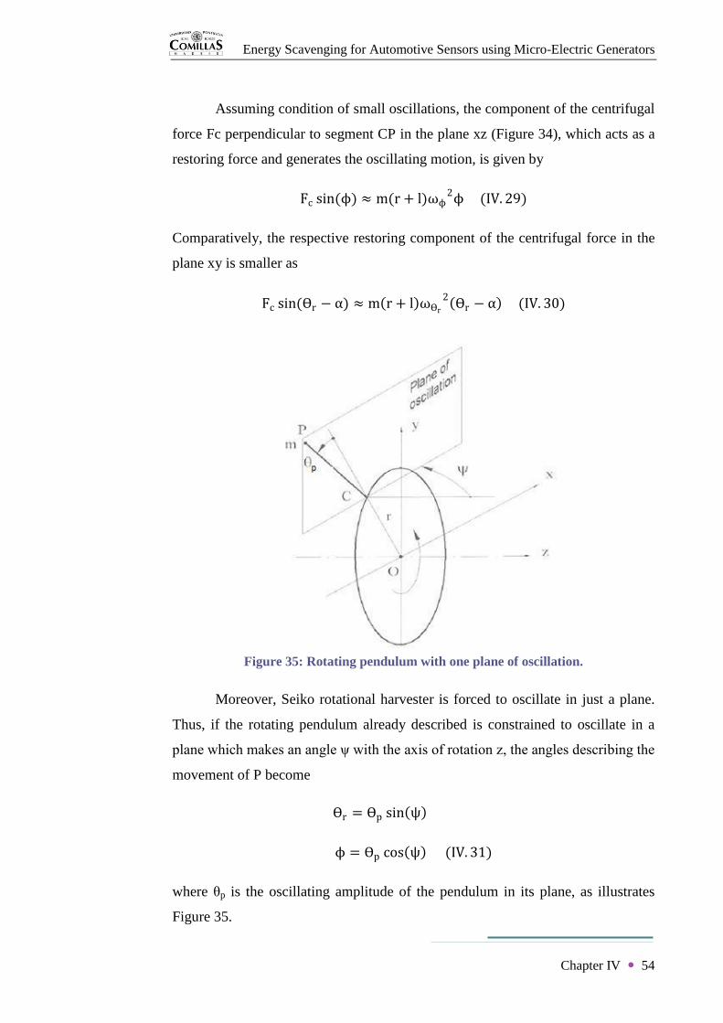
Energy Scavenging for Automotive Sensors using Micro-Electric Generators
Chapter IV 54
Assuming condition of small oscillations, the component of the centrifugal
force Fc perpendicular to segment CP in the plane xz (Figure 34), which acts as a
restoring force and generates the oscillating motion, is given by
Fc sin(ϕ) ≈ m(r + l)ωϕ2ϕ (IV. 29)
Comparatively, the respective restoring component of the centrifugal force in the
plane xy is smaller as
Fc sin(ϴr − α) ≈ m r + l ωϴr
2 ϴr − α (IV. 30)
Figure 35: Rotating pendulum with one plane of oscillation.
Moreover, Seiko rotational harvester is forced to oscillate in just a plane.
Thus, if the rotating pendulum already described is constrained to oscillate in a
plane which makes an angle ψ with the axis of rotation z, the angles describing the
movement of P become
ϴr = ϴp sin ψ
ϕ = ϴp cos ψ (IV. 31)
where θp is the oscillating amplitude of the pendulum in its plane, as illustrates
Figure 35.
Energy Scavenging for Automotive Sensors using Micro-Electric Generators
Chapter IV 55
Substituting these functions in equation (IV.21), the kinetic energy of the mass
becomes
E =1
2m r + l 2Ω 2 + l2ϴp
2
− lϴp2Ω 2 r + l cos2 ψ
+ 2l(r + l)Ω ϴp sin ψ (IV. 32)
Repeating the same analytic process, the linearized equation of motion is
lϴp + ϴpΩ
2 r + l cos2 ψ = 0 (IV. 33)
And the respective natural frequency obtained is
ωn = Ω r
l+ cos2 ψ (IV. 34)
The device is then operating as an oscillating rotational generator because the
natural frequency ωn equals zero when the excitation speed vanishes and the
restoring force is just caused by the centrifugal field. Hence, its maximum power
generated is given by equation (III.13).
Furthermore, the harvesting device can be improved at high excitation
speeds as a resonant oscillating rotational generator attaching a spring of stiffness
k between the mass and frame, which adds a restoring force toward the radial
direction. Introducing the potential energy of the spring U =1
2kϴp
2 on the
dynamic system and repeating the analytical demonstration, the linearized
equation of resonant motion is
ml2ϴp + mlΩ 2 r + l cos2 ψ + k ϴp = 0 (IV. 35)
And the natural frequency is then
ωn = k
ml2+ Ω 2
r
l+ cos2 ψ (IV. 36)
Therefore the device improves its maximum power generated given by equation
(III.17).

Energy Scavenging for Automotive Sensors using Micro-Electric Generators
Chapter IV 56
According to previous gravitational harvesting method, Seiko rotational
harvester is definitely restricted to be oriented in plane xy (ψ=90º) with the
purpose of generating notably more power at very low excitation speeds.
Moreover, the device will take significantly more advantage of the inertial
trajectory in its real application where peaks of acceleration exist, and therefore
the maximum generated power will greatly increase. Consequently, the rotational
harvester has definitely to be embedded in the same plane of the rotational
excitation at a radius r in the interior of the tyre. This specific operation is
analysed in detail next.
The current dynamical situation is now viewed from a relative reference ij
attached to the frame rotation, as illustrates Figure 36. From this point of view, the
frame of the device is stationary. The centrifugal force is depicted as a radial
Figure 36: Rotating pendulum from reference ij.
Energy Scavenging for Automotive Sensors using Micro-Electric Generators
Chapter IV 57
conservative potential field whose source is the center O of the wheel. And the
gravitational force, which rotates at velocity Ω with regard to reference ij, adds a
sinusoidal excitation of amplitude g and frequency Ω to the mass m in a given
position. This section takes advantage of the fact that at a certain excitation
velocity the centrifugal acceleration is large enough to take efficient advantage of
the rotational kinetic energy neglecting comparatively small disturbances caused
by the internal work done by the gravitational acceleration.
From Figure 36, the restoring torque caused by the centrifugal field is
expressed as
Tc = −l sin θr − α Fc (IV. 37)
And the value of the centrifugal force is
Fc = mΩ r cos(α) + l cos(θr − α) (IV. 38)
From equations (IV.37), (IV.38) and the geometrical expression
r sin(α) = l sin θr − α (IV. 39)
the oscillating restoring torque becomes
Tc = −mrlΩ 2 sin(θr) (IV. 40)
In this optimized operating configuration, the natural frequency of the
pendulum is given by ωn = Ω r/l from equation (IV.34) with ψ=90º. In this case
of application, the radius r of the wheel rim is much larger than the pendulum
length l. Therefore the natural frequency of oscillation is always going to be
proportional and higher than the frequency of excitation. This can then lead to
small displacement amplitudes and consequently to insufficient power levels.
However, the actual semi-circular proof mass has to be included as a
distributed pendulum on this dynamical model. Thus the natural frequency of the
distributed pendulum in a centrifugal field becomes
ωn = m(rΩ 2)Rg
I= Ω
mrRg
I (IV. 41)
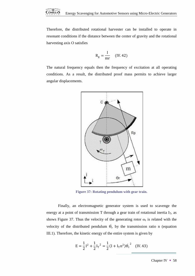
Energy Scavenging for Automotive Sensors using Micro-Electric Generators
Chapter IV 58
Therefore, the distributed rotational harvester can be installed to operate in
resonant conditions if the distance between the center of gravity and the rotational
harvesting axis O satisfies
Rg =I
mr (IV. 42)
The natural frequency equals then the frequency of excitation at all operating
conditions. As a result, the distributed proof mass permits to achieve larger
angular displacements.
Finally, an electromagnetic generator system is used to scavenge the
energy at a point of transmission T through a gear train of rotational inertia IT, as
shows Figure 37. Thus the velocity of the generating rotor ωr is related with the
velocity of the distributed pendulum ϴr by the transmission ratio n (equation
III.1). Therefore, the kinetic energy of the entire system is given by
E =1
2I2 +
1
2IT
2 =1
2 I + ITn2 ϴr
2 (IV. 43)
Figure 37: Rotating pendulum with gear train.

Energy Scavenging for Automotive Sensors using Micro-Electric Generators
Chapter IV 59
where the equivalent rotational inertia is defined as
I′ = I + ITn2 (IV. 44)
The natural frequency of the system becomes then
ωn = Ω mrRg
I′ (IV. 45)
And the condition to achieve resonance at every excitation frequency is
I′ = mrRg (IV. 46)
Consequently, this complete dynamic implementation of the studied rotational
harvester during operation solves motion constraints of previous configurations. It
is then proved that the device can be designed for achieving power levels required
by a specific application.
4. Conclusion of chapter IV
It can be concluded from the previous dynamic analysis that Seiko
rotational electromagnetic harvesting system can be design to scavenge reasonable
power levels for TPMS application. The geared distributed pendulum has to be
oriented in the vertical plane of wheel rotation. Thus the main operating method
scavenges the energy from oscillating motion caused by the centrifugal field. The
maximum energy generation demands a resonant response to constant excitation
speeds for achieving the largest amplitudes of the internal magnetic rotor motion.
At very low speeds, the system scavenges the energy from the opposition of the
gravitational field.
Energy Scavenging for Automotive Sensors using Micro-Electric Generators
60
CHAPTER V
Experimentation

Energy Scavenging for Automotive Sensors using Micro-Electric Generators
Chapter V 61
Chapter V
Experimentation
It has been analytically demonstrated that studied Seiko harvesting
technology can be redesigned to power other electronic packages. This is
confirmed by a recent innovative design based on watch AGS components which
supplies power to sensors mounted on marine mammals, scavenging the motion of
the animal. Since the sensor package is larger, as shows Figure 38, the levels of
power were scaled up between 5 mW and 10 mW. This chapter aims to test Seiko
wristwatch to obtain experimental data of its power potential.
1. Experimental starting
Seiko wristwatch testing called for being able to spin the mass spindle at a
specific controlled angular speed. With this purpose, an assembly was devised to
replace the mechanical function of the proof mass.
Figure 38: Marine mammal package.
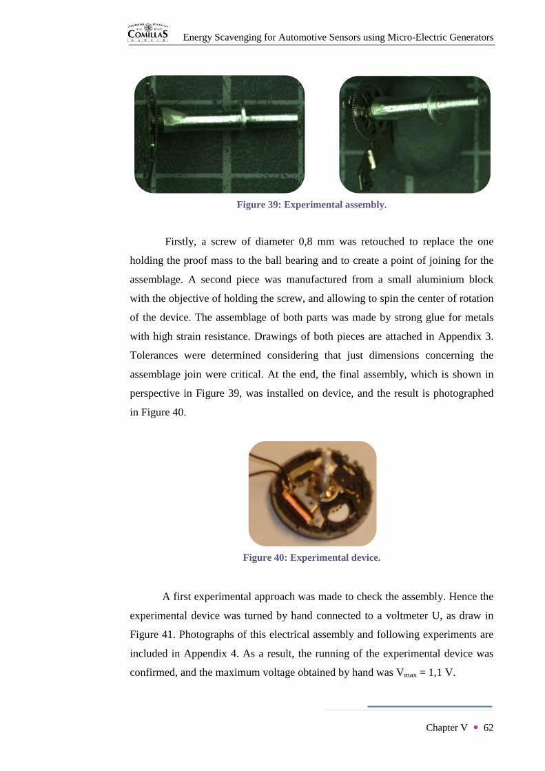
Energy Scavenging for Automotive Sensors using Micro-Electric Generators
Chapter V 62
Firstly, a screw of diameter 0,8 mm was retouched to replace the one
holding the proof mass to the ball bearing and to create a point of joining for the
assemblage. A second piece was manufactured from a small aluminium block
with the objective of holding the screw, and allowing to spin the center of rotation
of the device. The assemblage of both parts was made by strong glue for metals
with high strain resistance. Drawings of both pieces are attached in Appendix 3.
Tolerances were determined considering that just dimensions concerning the
assemblage join were critical. At the end, the final assembly, which is shown in
perspective in Figure 39, was installed on device, and the result is photographed
in Figure 40.
A first experimental approach was made to check the assembly. Hence the
experimental device was turned by hand connected to a voltmeter U, as draw in
Figure 41. Photographs of this electrical assembly and following experiments are
included in Appendix 4. As a result, the running of the experimental device was
confirmed, and the maximum voltage obtained by hand was Vmax = 1,1 V.
Figure 40: Experimental device.
Figure 39: Experimental assembly.

Energy Scavenging for Automotive Sensors using Micro-Electric Generators
Chapter V 63
2. Experiment 1
Subsequently, the experimental device was installed in a small lathe with
the purpose of spinning its handle piece at a constant known velocity.
Furthermore, the same previous circuit of Figure 41 was assembled again. The
experiment was about reading rms voltage measurements at steady state as
velocity of excitation was increased gradually. The rotational speed of the lathe
was precisely determined using a laser digital tachometer (Appendix 4).
Consequently, the open-circuit voltage of the device was obtained with respect to
constant excitation speed Ω in rpm. Resulting curve is illustrated in Figure 42.
Figure 42: Open-circuit generated voltage.
0
5
10
15
20
25
30
0 200 400 600 800 1000 1200 1400 1600 1800 2000
Vo
ltag
e (
V)
Speed (rpm)
Figure 41: Voltage measurement circuit.

Energy Scavenging for Automotive Sensors using Micro-Electric Generators
Chapter V 64
As observed in the graph, it can be concluded that the output voltage and the
angular velocity of the source are linearly related by
V = 0,01482π
60Ω = 0,00155Ω (V. 1)
3. Experiment 2
This second experiment aims for characteristic operational curves of Seiko
generator with respect to constant excitation speed. The lathe was then used again
as source of excitation. As demonstrated, the maximum power generation occurs
when the coil resistance Rc matches with the external load R. Thus the circuit of
Figure 43 was assembled using R2 = 327 Ω , an ammeter A and a voltmeter U
(Appendix 4).
Figure 43: Generation measurement circuit.
Along the experiment, rms current and rms voltage measurements were
read at a steady state as the lathe spindle speed was increased gradually. As a
result, curves of intensity and voltage generated by the device with respect to the
excitation speed were obtained, and drawn respectively in Figure 44 and Figure
45. Consequently, the maximum average power delivered by Seiko device was
directly deduced, since P = VI. This last graph is shown in Figure 46.

Energy Scavenging for Automotive Sensors using Micro-Electric Generators
Chapter V 65
Figure 44: Intensity generated.
Figure 45: Voltage generated.
0
0,5
1
1,5
2
2,5
3
3,5
0 200 400 600 800 1000 1200 1400 1600
Inte
nsit
y (
mA
)
Speed (rpm)
0
0,2
0,4
0,6
0,8
1
1,2
0 200 400 600 800 1000 1200 1400 1600
Vo
ltag
e (
V)
Speed (rpm)

Energy Scavenging for Automotive Sensors using Micro-Electric Generators
Chapter V 66
Figure 46: Power generation.
It can be observed that at high frequencies of excitation the device
generating behaviour becomes constant. Voltage and reactance of the harvesting
generator are proportional to the frequency of excitation. And their values are
given respectively by equation (V.1) and X = LΩ . Therefore the output
alternating current is expressed as
I =V
Z=
0,00155Ω
Rc + R 2 + LΩ 2
(V. 2)
Thus the generating saturation observed appears because the resistance term can
be neglected in comparison with the much higher inductance term at high speeds
of excitation. Hence, V and Z are proportional to the excitation speed at high
frequencies, and consequently its quotient I is constant.
4. Conclusion of chapter V
It has been proved that Seiko rotational harvester achieves a maximum
power around 3 mW. This power level is enough to feed a common TPMS sensor
0
0,5
1
1,5
2
2,5
3
3,5
0 200 400 600 800 1000 1200 1400 1600
Po
wer
(mW
)
Speed (rpm)

Energy Scavenging for Automotive Sensors using Micro-Electric Generators
Chapter V 67
package and permit its RF transmissions. However, it has to be determined if the
speed levels required to obtain that generation are reached while the harvester
operates in its application. A numerical discussion has then to be done using
previous experimental curves, dynamic formulations and scavenging methods
described about Seiko rotational electromagnetic generator.

Energy Scavenging for Automotive Sensors using Micro-Electric Generators
68
CHAPTER VI
Results
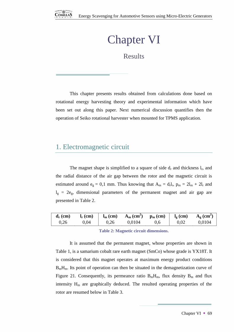
Energy Scavenging for Automotive Sensors using Micro-Electric Generators
Chapter VI 69
Chapter VI
Results
This chapter presents results obtained from calculations done based on
rotational energy harvesting theory and experimental information which have
been set out along this paper. Next numerical discussion quantifies then the
operation of Seiko rotational harvester when mounted for TPMS application.
1. Electromagnetic circuit
The magnet shape is simplified to a square of side dr and thickness lr, and
the radial distance of the air gap between the rotor and the magnetic circuit is
estimated around eg = 0,1 mm. Thus knowing that Am = drlr, pm = 2lm + 2lr and
lg = 2eg, dimensional parameters of the permanent magnet and air gap are
presented in Table 2.
dr (cm) lr (cm) lm (cm) Am (cm2) pm (cm) lg (cm) Ag (cm
2)
0,26 0,04 0,26 0,0104 0,6 0,02 0,0104
Table 2: Magnetic circuit dimensions.
It is assumed that the permanent magnet, whose properties are shown in
Table 1, is a samarium cobalt rare earth magnet (SmCo) whose grade is YX18T. It
is considered that this magnet operates at maximum energy product conditions
BmHm. Its point of operation can then be situated in the demagnetization curve of
Figure 21. Consequently, its permeance ratio BmHm, flux density Bm and flux
intensity Hm are graphically deduced. The resulted operating properties of the
rotor are resumed below in Table 3.

Energy Scavenging for Automotive Sensors using Micro-Electric Generators
Chapter VI 70
BmHm (G.Oe) Bm/Hm Bm (G) Hm (G)
1,80E+07 1 4243 4243
Table 3: Operational properties of the permanent magnet.
Furthermore, the leakage factor is obtained from equation (III.4). And finally the
flux density on the air gap Bg is calculated from equation (III.3). Those final
results are shown in Table 4.
K Bg (G) Bg (T) B (T)
2,13 1993 0,1993 0,1993
Table 4: Air gap results.
Neglecting reluctance in the ferromagnetic circuit Vf = 0, it can be
concluded that the magnetic field B going through the coil, with the permanent
magnet YX18T designed for a maximum harvesting generation, is equal to the
value of flux density on the air gap Bg (Table 4).
2. Oscillating operation
Firstly, common vehicle dimensions have been chosen for the external
radius of a wheel rmax and also its rim radius r, where the energy harvesting device
is placed. Those parameters are presented together with dynamic properties of the
proof mass in Table 5.
r (m) rmax (m) m (kg) Rp (m) Rg (m) I (kg.m2)
0,2032 0,205 0,0048 0,0135 0,00573 2,19E-07
Table 5: Parameter of wheel and oscillating weight.
Moreover, the vehicle speed v and the corresponding wheel speed Ω are related
by
Ω =v
3,6rmax (VI. 1)

Energy Scavenging for Automotive Sensors using Micro-Electric Generators
Chapter VI 71
Hence, the acceleration ϴr and restoring torque Tc of the proof mass for a certain
relative angle ϴr can be calculated respectively from equations (IV.27) and
(IV.40). Furthermore, the natural frequency of the mass wn, and consequently the
rotor frequency wr are deduced from equations (IV.41) and (III.1). Those
calculations have been done for ϴr = 30º until v = 120 km/h, and results are
shown in Figure 47, Figure 48, Figure 49 and Figure 50 below.
Figure 47: Natural frequency wn and wheel speed Ω with respect to vehicle velocity.
Figure 48: Rotor frequency wr regarding v.
0
1000
2000
3000
4000
5000
6000
7000
8000
0 20 40 60 80 100 120
Fre
qu
en
cy (
rpm
)
v (km/h)
Natural frequency Wheel velocity
0
100000
200000
300000
400000
500000
600000
700000
800000
0 20 40 60 80 100 120
Fre
qu
en
cy o
f ro
tor
(rp
m)
v (km/h)
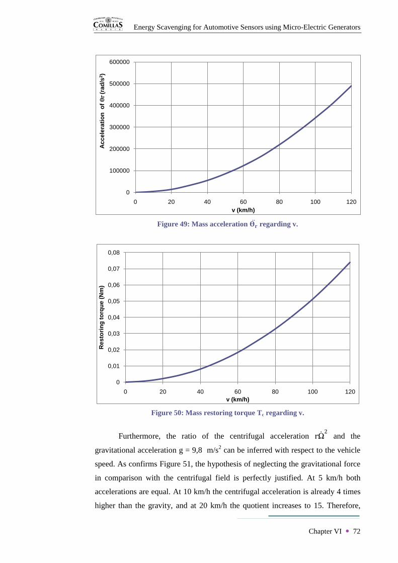
Energy Scavenging for Automotive Sensors using Micro-Electric Generators
Chapter VI 72
Figure 49: Mass acceleration 𝚹𝐫 regarding v.
Figure 50: Mass restoring torque Tc regarding v.
Furthermore, the ratio of the centrifugal acceleration rΩ 2 and the
gravitational acceleration g = 9,8 m/s2 can be inferred with respect to the vehicle
speed. As confirms Figure 51, the hypothesis of neglecting the gravitational force
in comparison with the centrifugal field is perfectly justified. At 5 km/h both
accelerations are equal. At 10 km/h the centrifugal acceleration is already 4 times
higher than the gravity, and at 20 km/h the quotient increases to 15. Therefore,
0
100000
200000
300000
400000
500000
600000
0 20 40 60 80 100 120
Ac
ce
lera
tio
n o
f ϴ
r (r
ad
/s2)
v (km/h)
0
0,01
0,02
0,03
0,04
0,05
0,06
0,07
0,08
0 20 40 60 80 100 120
Res
tori
ng
to
rqu
e (
Nm
)
v (km/h)

Energy Scavenging for Automotive Sensors using Micro-Electric Generators
Chapter VI 73
apart from very low speeds of the vehicle, Seiko rotational generator operates
definitely as an oscillating energy harvesting device.
Figure 51: 𝐫Ω 𝟐/g ratio regarding v.
Secondly, a Matlab model of the device operation in TPMS application has
been programmed with the purpose of obtaining the oscillating amplitude of the
proof mass from non linear equations of motion (IV.18) when Ω = 0. The
electromagnetic constant ke used has been estimated around 0,04 Vs/rad from
equation (IV.15). Consequently, the number of turns N of the coil results 100
from equation (II.7). Simulations of this model make a distinction again between
the stationary motion of the weight at very low speeds of the wheel and its more
common oscillating displacement.
Three different behaviours of the weight are then observed. At very low
speeds the harvesting method changes because of the mass stationary motion, and
therefore this particular case will be detailed on next section. From v = 5 km/h
(Ω = 65 rpm), where gravity and centrifugal force coincide, until v = 16 km/h
(Ω = 207 rpm), where centrifugal field is just one order of magnitude higher, a
zone of motion transition between stationary and sinusoidal large oscillations
takes place. In this particular zone, the mass response to a constant excitation
0
100
200
300
400
500
600
0 20 40 60 80 100 120
Ra
tio
ac
en
t./g
v (km/h)

Energy Scavenging for Automotive Sensors using Micro-Electric Generators
Chapter VI 74
speed progresses from random oscillations with small amplitudes, as the example
of Figure 52, to sinusoidal oscillations with progressively less dampening effect.
Figure 52: Mass relative angle ϴr(t) for v= 6 km/h.
Above those speeds of excitation, the mass motion follows large oscillating
amplitudes with high natural frequencies, as for instance the case of Figure 53.
0 0.1 0.2 0.3 0.4 0.5 0.6 0.7 0.8-250
-200
-150
-100
-50
0
50
Time (s)
Rela
tive a
ngle
(deg)
Relative Angular Position for Speed = 8 rad/s and Initial Condition = 0 degs
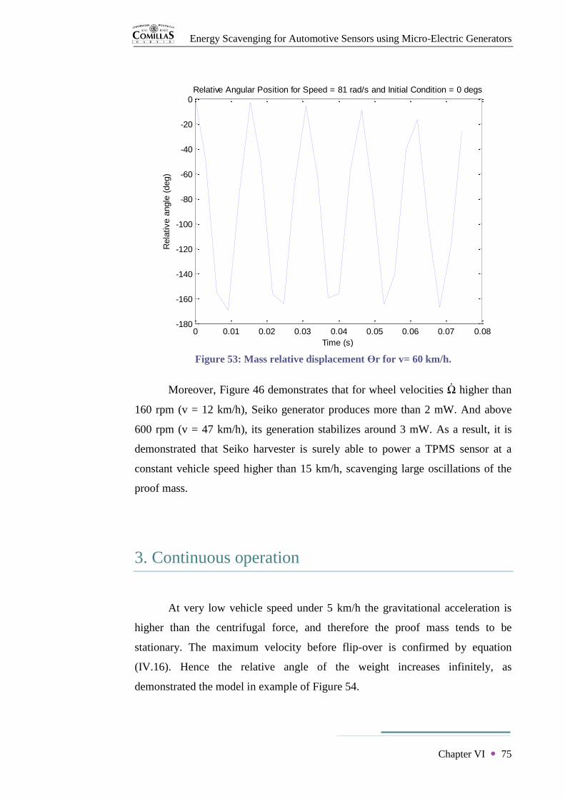
Energy Scavenging for Automotive Sensors using Micro-Electric Generators
Chapter VI 75
Figure 53: Mass relative displacement ϴr for v= 60 km/h.
Moreover, Figure 46 demonstrates that for wheel velocities Ω higher than
160 rpm (v = 12 km/h), Seiko generator produces more than 2 mW. And above
600 rpm (v = 47 km/h), its generation stabilizes around 3 mW. As a result, it is
demonstrated that Seiko harvester is surely able to power a TPMS sensor at a
constant vehicle speed higher than 15 km/h, scavenging large oscillations of the
proof mass.
3. Continuous operation
At very low vehicle speed under 5 km/h the gravitational acceleration is
higher than the centrifugal force, and therefore the proof mass tends to be
stationary. The maximum velocity before flip-over is confirmed by equation
(IV.16). Hence the relative angle of the weight increases infinitely, as
demonstrated the model in example of Figure 54.
0 0.01 0.02 0.03 0.04 0.05 0.06 0.07 0.08-180
-160
-140
-120
-100
-80
-60
-40
-20
0
Time (s)
Rela
tive a
ngle
(deg)
Relative Angular Position for Speed = 81 rad/s and Initial Condition = 0 degs

Energy Scavenging for Automotive Sensors using Micro-Electric Generators
Chapter VI 76
Figure 54: Mass relative displacement ϴr for v= 2 km/h.
Thus the Seiko generator operates in this zone as a continuous energy harvesting
device. The power generated on this situation is then calculated from equation
(III.21). Results, which are presented in Figure 55, show that the power level
along this behaviour is always under 2 mW. As a result, it is demonstrated that at
very low speeds, in which the mass oscillating motion do not occurs, the power
generation is not enough to feed directly a TPMS sensor package.
0 0.5 1 1.5 2 2.5-50
0
50
100
150
200
250
300
350
Time (s)
Rela
tive a
ngle
(deg)
Relative Angular Position for Speed = 3 rad/s and Initial Condition = 0 degs

Energy Scavenging for Automotive Sensors using Micro-Electric Generators
Chapter VI 77
Figure 55: Power generated under v = 5km/h.
All estimations of this project have been done considering constant the
wheel velocity Ω because of the appearance of the non linear chaotic behaviour.
In real application, the introduction of very high accelerations of the wheel mostly
at speeds lower than 15 km/h will increase the achieved power level. Hence,
generation difficulties of the zone of transition between 5 km/h and 15 km/h will
be certainly overcome. Furthermore, the addition of an energy processor and
storage interface will make available for use the energy harvested under 2 mW at
very low vehicle speeds. Finally, it has to be specified that an initial acceleration
perturbation is essential to provoke the required oscillating motion at high speeds.
If accelerations were not considered, the relative angle ϴr of proof mass would
stay nil along cycles at very high speeds, and no power would be generated. In
other words, the mass would always maintain a radial orientation, rotating at the
same speed of the wheel. Therefore, wheel perturbations and accelerations are
fundamental for scavenging suitable power levels from this environment.
Finally, the theoretical power levels discussed in this section have been
confirmed by a PSpice model built with ICES software. The simulations have
been carried out with the characteristics parameters defined for Seiko device.
Appendix 5 present the model utilized.
0
0,0002
0,0004
0,0006
0,0008
0,001
0,0012
0,0014
0,0016
0,0018
0,002
0 1 2 3 4 5
Po
we
r g
en
era
ted
(W
)
v (km/h)
Energy Scavenging for Automotive Sensors using Micro-Electric Generators
Chapter VI 78
4. Conclusion of chapter VI
It can be concluded that Seiko current wristwatch is prepared for
scavenging enough power for TPMS sensors above 15 km/h. A device redesign
will be able to overcome generation problems at low speeds trying to eliminate the
gravitational harvesting method introducing oscillating resonance at all operating
conditions. As in all harvesting devices, a storage system will manage and make
the most of zones of poor harvesting power. Moreover, optimizing as much as
possible the power needed by a TPMS wireless sensor system through power
management techniques is the first approach before improving a compact design.

Energy Scavenging for Automotive Sensors using Micro-Electric Generators
79
CHAPTER VII
Miniaturization

Energy Scavenging for Automotive Sensors using Micro-Electric Generators
Chapter VII 80
Chapter VII
Miniaturization
In the centimetre scale, the experimented wristwatch system can deliver
milliwatts required by sensor application through rotational motion conversion. A
micro-electro-mechanical system (MEMS) is the integration of mechanics and
electronics on a common silicon substrate. Thus electromechanical devices are
produces by a micro-fabrication technology that specifically adds structural layers
or etches away parts of a silicon wafer. Therefore, if miniaturization of Seiko
rotational electromagnetic device could be achieved, it would be possible to
develop a complete autonomous TPMS sensing system.
1. Scaling considerations
Dimensional factors of the harvesting device have to be discussed to
determine if the adoption of miniaturization design, whose cost is supported by
the commercial implication of the project, is accurate. Some parameters have to
be considered to keep the power generated at the level required by the application
as the device scale decreases. Even so, it do not exist any conclusive theory or
experimental studies about miniaturized rotational generators under a diameter
lower than 5 mm. Therefore, issues as dynamics of high rotation, winding
resistance or magnetism of permanent magnet are unexplored at those
microscopic levels.
It is defined that A is a characteristic length of the rotational harvesting
device. On one hand, permanent magnet magnetization Bm and consequently the
electromagnetic constant ke scale as A2. On the other hand, coil resistance Rc
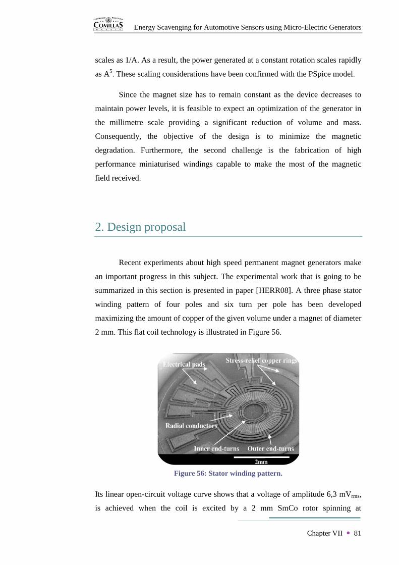
Energy Scavenging for Automotive Sensors using Micro-Electric Generators
Chapter VII 81
scales as 1/A. As a result, the power generated at a constant rotation scales rapidly
as A5. These scaling considerations have been confirmed with the PSpice model.
Since the magnet size has to remain constant as the device decreases to
maintain power levels, it is feasible to expect an optimization of the generator in
the millimetre scale providing a significant reduction of volume and mass.
Consequently, the objective of the design is to minimize the magnetic
degradation. Furthermore, the second challenge is the fabrication of high
performance miniaturised windings capable to make the most of the magnetic
field received.
2. Design proposal
Recent experiments about high speed permanent magnet generators make
an important progress in this subject. The experimental work that is going to be
summarized in this section is presented in paper [HERR08]. A three phase stator
winding pattern of four poles and six turn per pole has been developed
maximizing the amount of copper of the given volume under a magnet of diameter
2 mm. This flat coil technology is illustrated in Figure 56.
Figure 56: Stator winding pattern.
Its linear open-circuit voltage curve shows that a voltage of amplitude 6,3 mVrms,
is achieved when the coil is excited by a 2 mm SmCo rotor spinning at
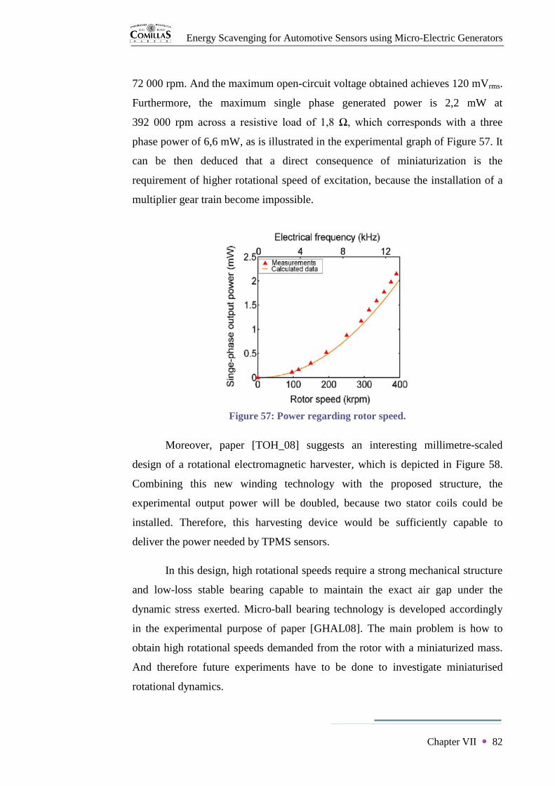
Energy Scavenging for Automotive Sensors using Micro-Electric Generators
Chapter VII 82
72 000 rpm. And the maximum open-circuit voltage obtained achieves 120 mVrms.
Furthermore, the maximum single phase generated power is 2,2 mW at
392 000 rpm across a resistive load of 1,8 Ω, which corresponds with a three
phase power of 6,6 mW, as is illustrated in the experimental graph of Figure 57. It
can be then deduced that a direct consequence of miniaturization is the
requirement of higher rotational speed of excitation, because the installation of a
multiplier gear train become impossible.
Figure 57: Power regarding rotor speed.
Moreover, paper [TOH_08] suggests an interesting millimetre-scaled
design of a rotational electromagnetic harvester, which is depicted in Figure 58.
Combining this new winding technology with the proposed structure, the
experimental output power will be doubled, because two stator coils could be
installed. Therefore, this harvesting device would be sufficiently capable to
deliver the power needed by TPMS sensors.
In this design, high rotational speeds require a strong mechanical structure
and low-loss stable bearing capable to maintain the exact air gap under the
dynamic stress exerted. Micro-ball bearing technology is developed accordingly
in the experimental purpose of paper [GHAL08]. The main problem is how to
obtain high rotational speeds demanded from the rotor with a miniaturized mass.
And therefore future experiments have to be done to investigate miniaturised
rotational dynamics.

Energy Scavenging for Automotive Sensors using Micro-Electric Generators
Chapter VII 83
Figure 58: Miniaturisation proposal.
3. Conclusion of chapter VII
In conclusion, current promising results indicate that a miniaturized
rotational electromagnetic generator is a reasonable and feasible approach for
generating milliwatts in a millimetre scale. Future experimentation will surely
overcome present ignorance and limitations about rotational micro-harvesting, and
consequently achieve the design of a new autonomous TPMS sensor package
(Figure 59) that will provide eagerly awaited environmental, safety and economic
advantages.
Figure 59: Autonomous TPMS.
Energy Scavenging for Automotive Sensors using Micro-Electric Generators
84
CHAPTER VIII
Conclusions

Energy Scavenging for Automotive Sensors using Micro-Electric Generators
Chapter VIII 85
Chapter VIII
Conclusions
Low pressure tyres cause important safety concerns, and Direct TPMS is
hugely beneficial alleviating those issues. This system will be highly improved
developing a reliable energy harvesting device that will make the wireless sensor
package truly autonomous, eliminating completely the need for battery changes.
This objective involves significant commercial and environmental advantages.
Rotational electromagnetic conversion is the most appropriate energy
harvesting method for powering this application from wheel motion. In particular,
kinetic wristwatch technology eliminates maintenance through rotational
inductive micro-generation and later storage in a rechargeable battery. Power is
scavenged from the relative displacement between the proof mass and the frame.
And the generation level relies on either a continuous or an oscillating motion of
the weight.
Powering TPMS sensors, that harvesting device has to be oriented with the
plane of rotation of the wheel. Generally, its operation is based on scavenging the
kinetic energy from high frequency oscillations caused by the centrifugal field,
which dominates tremendously facing gravity insignificant perturbations. At very
low speeds, its operation depends on scavenging the energy from the stationary
motion of the weight caused by predominant vertical opposition of the
gravitational field. Complying with this pattern, the device generates between
2 mW and 3 mW above a vehicle speed of 15 km/h. Under this limit, the
generation falls off into unsatisfactory power levels for TPMS radio frequency
modules.
The largest amplitudes of the internal permanent magnet and consequent
maximum output power are achieved for oscillating resonant motion of the

Energy Scavenging for Automotive Sensors using Micro-Electric Generators
Chapter VIII 86
weight. Therefore a device redesign will overcome poor generation at low speeds
deleting the gravitational harvesting method through the introduction of that
response at all operating constant conditions. The addition of an energy
management and storage system will definitely enable wireless pressure sensors to
accomplish their transmissions under all possible operating conditions during the
vehicle entire life with low cost and high reliability, thanks to rotational
electromagnetic energy harvesting.
Subsequent miniaturisation proposal is able to achieve a maximum single-
phase power of 4,4 mW. Whereas it is not conceived how to achieve the high
inertial excitations required by the rotor, experimental results encourage future
researches to focus on millimetre-scaled rotational electromagnetic generation as a
viable milliwatt powering technology. Consequently, future MEMS performance
will surely permit to introduce this infinite source unit into the pressure sensor
itself achieving an autonomous package that will contribute to important
environmental, economic and safety advantages.

Energy Scavenging for Automotive Sensors using Micro-Electric Generators
87
REFERENCES

Energy Scavenging for Automotive Sensors using Micro-Electric Generators
References 88
References
[WEST94] Automotive sensors, M H Westbrook & J D Turner, IOP, 1994.
[CHOW95] Automobile Electronics, Eric Chowanietz, BH, 1995.
[FREN89] Tyre Technology, Tom French, Adam Hilger, 1989.
[GILL92] Fundamentals of Vehicle Dynamics, Thomas D. Gillespie, Society of
Automotive Engineers, 1992.
[HEIN02] Advanced Vehicle Technology, HeinzHeisler, BH, 2002.
[NHTS00] Federal Motor Vehicle Safety Standards; Tire Pressure Monitoring
Systems; Controls and Displays, DOT, NHTSA, 49 CFR Part 571, Docket No.
NHTSA 2000-8572, RIN 2127-AI33.
[DIXO91] Tires, Suspension and Handling, 2nd
edition, John C. Dixon, SAE,
1991.
[OHBA92] Intelligent Sensor Technology, Ryoji Ohba, WILEY, 1992.
[BERN93] Maintenance-Free Batteries, D. Berndt, RSP, 1993.
[RIST94] Sensor technology and devices, Ljubisa Ristic, Artech House, 1994.
[NHTS01] Tire Safety Information; Proposed Rule, DOT, NHTSA, 49 CFR Parts
657, 571, 574 and 575, Docket No. NHTSA-01-11157, RIN 2127-AI32.
[VENK07] MEMS Pressure Sensors in the Automotive Industry, Prashanth
Venkatesh, Frost & Sullivan, 2007.
[REAB97] Batteries for automotive use, P.Reabeck & J.G. Smith, RSP, 1997.
[TORR05] Harvesting ambient energy will make embedded devices autonomous,
Erick O. Torres & Gabriel A. Rincon-Mora, EE Times, 2005.
[GOET05] Photovoltaic Solar Energy Generation, A. Goetzberger & V.U.
Hoffmann, Springer, 2005.
[MERR82] Sunlight to Electricity, 2nd
edition, Josepha Merrigan, MIT Press,
1982.
[ROWE94] Handbook of Thermoelectrics, D.M. Rowe, CRC, 1994.
[HARM67] Thermoelectric and Thermomagnetic Effects and Applications,
Harman & Honig, McGraw-Hill, 1967.

Energy Scavenging for Automotive Sensors using Micro-Electric Generators
References 89
[GAUT02] Piezoelectric Sensorics, G.Gautschi, Springer, 2002.
[CROS87] Electrostatics Principles, Problems and Applicacions, J.A. Cross,
Adam Hilger, 1987.
[SHEN87] Applied Electromagnetism, 2nd
edition, Liang Chi Shen & Jin Au
Kong, PWS, 1987.
[KRAU89] Electromechanical Motion Devices, Paul C. Krause & Oleg
Wasynczuk, McGraw-Hill, 1989.
[BISW__] Design of a MEMPS using a Microgenerator, Nipun Biswas, Nikhit
Nair, Rosa Ciprian & Anindita Bhattacharya.
[CHIN00] PCB Integrated Micro-generator for Wireless Systems, Neil N.H.
Ching, Gordon M.H. Chan, Wen J. Li, Hiu Yung Wong & Philip H.W. Leong,
The Chinese University if Hong Kong, 2000.
[BEEB08] Kinetic Energy Harvesting, S.P. Beeby, R.N. Torah & M.J. Tidor,
University of Southampton, 2008.
[GILB08] Comparison of Energy Harvesting Systems for Wireless Sensor
Networks, James M. Gilbert & Farooq Balouchi, University of Hull, 2008.
[JENS84] Fundamentals of Energy Storage, Johanness Jensen & Bent Sorensen,
Wiley-Iterscience, 1984. (Chapter 7: Electrochemical Energy Conversion and
Storage p. 141-205.)
[GABA83] Lithium Batteries, Jean-Paul Gabano, Academic Press, 1983.
[VULL08] Energy Harvesting or Micropower Generation for Wireless
Autonomous Sensors, Ruud Vullers, Holst Center/IMEC-NL, 2008.
[RAWL93] The Science of Clocks & Watches, 3rd
edition, A.L. Rawlings, British
Horological Institute, 1993.
[SEIK08] Parts Catalogue & Technical Guide, Cal. 5M62A, 5M63A, UK Seiko,
2008.
[WRIG06] Energy Scavenging/Harvesting, Paul Wright, ITRIS, 2006.
[NASA79] Electromechanics and Electric Machines, S.A. Nasar & L.E.
Unnewehr, John Wiley & Sons, 1979.
[WEAV82] Electrical and Electronic Clocks and Watches, J.D. Weaver, Newnes
Technical Books, 1982.
[YEAT07] Energy harvesting from motion using rotating and gyroscopic proof
masses, E.M. Yeatman, Imperial College London, 2007.

Energy Scavenging for Automotive Sensors using Micro-Electric Generators
References 90
[TOH_08] A continuously rotating energy harvester with maximum power point
tracking, Tzern T. Toh, Paul D. Mitcheson, Andrew S. Holmes & Eric M
Yeatman, Imperial College, 2008.
[GENT05] Dynamics of rotating systems, Giancarlo Genta, Springer, 2005.
[CONR05] Development of an Inertial Generator for Embedded Applications in
Rotating Environments, Stephen D. Conrad, University of Cincinnati,
Massachusetts Institute of Technology 2005.
[PARA05] Energy Harvesting for Mobile Computing, Joe Paradiso, Responsive
Environments Group, MIT Media Lab, 2005.
[MOOR88] The Modern Bicyble Dynamo, Guy S.M. Moore, Hatfield Polytechnic,
1988.
[COME86] Microprocessor-Based System Design, David J. Comer, HRW, 1986.
[RAO_08] Imperial College Energy-Harvesting Simulator (ICES), Kondala Rao,
Paul D. Mitcheson & Tim C. Green, Imperial College London, 2008.
[ARMS05] Power Management for Energy Harvesting Wireless Sensors, S.W.
Arms, C.P. Townsend, D.L. Churchill, J.H. Galbreath & S.W. Mundell,
MicroStrain, 2005.
[BROD82] The Physics of Microfabrication, Ivor Brodie & Julius J. Muray,
Plenum, 1982.
[HERR08] Ultraminiaturized High-Speed Permanent-Magnet Generators for
Milliwatt-Level Power Generation, Florian Herrault, Chang-Hyeon Ji & Mark G.
Allen, IEEE, 2008.
[GHAL08] Design, Fabrication, and Characterization of a Rotary Micromotor
Supported on Microball Bearings, Nima Ghalichechian, Alireza Modafe, Mustafa
Ilker Beyaz, & Reza Ghodssi, IEEE, 2008.

Energy Scavenging for Automotive Sensors using Micro-Electric Generators
APPENDIX
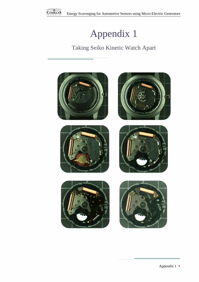
Energy Scavenging for Automotive Sensors using Micro-Electric Generators
Appendix 1
Appendix 1
Taking Seiko Kinetic Watch Apart

Energy Scavenging for Automotive Sensors using Micro-Electric Generators
Appendix 1
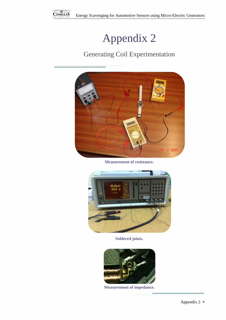
Energy Scavenging for Automotive Sensors using Micro-Electric Generators
Appendix 2
Appendix 2
Generating Coil Experimentation
Measurement of resistance.
Measurement of impedance.
Soldered joints.

Energy Scavenging for Automotive Sensors using Micro-Electric Generators
Appendix 3
Appendix 3
Assembly Drawings

Energy Scavenging for Automotive Sensors using Micro-Electric Generators
Appendix 4
Appendix 4
Watch Experimentation
Experimental assembly checking circuit. Digital tachometer.
Measurement of open-circuit voltage at a constant speed.
Measurement of current/voltage generated to an external load at a constant speed.
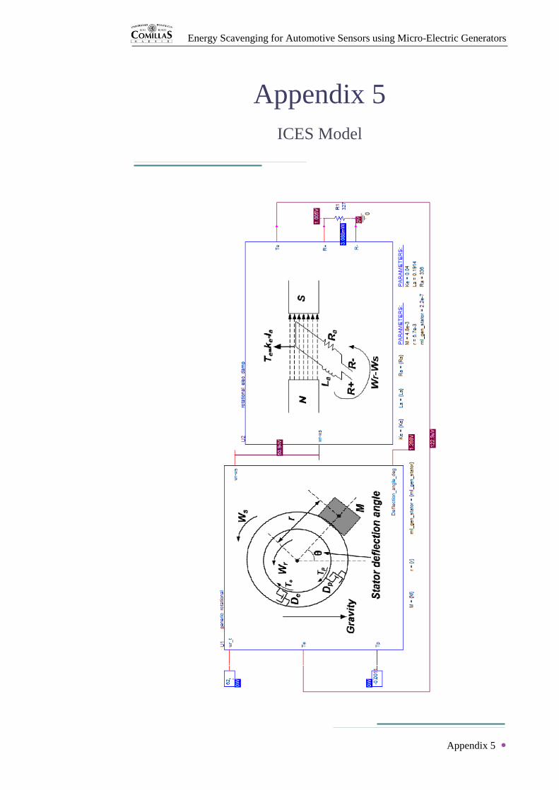
Energy Scavenging for Automotive Sensors using Micro-Electric Generators
Appendix 5
Appendix 5
ICES Model

Energy Scavenging for Automotive Sensors using Micro-Electric Generators
Appendix 6
Appendix 6
Previous Documents