
Energy saving and pollution control in urea plant though prilling tower and other equipments (1)
16
See discussions, stats, and author profiles for this publication at: https://www.researchgate.net/publication/304706538 Energy Saving and Pollution Control in Urea Plant Though Prilling Tower and Other Equipments Article · July 2016 DOI: 10.14445/22315381/IJETT-V36P266 2 authors, including: Prem Baboo National Fertilizers Ltd.,India 34 PUBLICATIONS 0 CITATIONS SEE PROFILE Available from: Prem Baboo Retrieved on: 02 July 2016
-
Upload
prem-baboo -
Category
Engineering
-
view
333 -
download
1
Transcript of Energy saving and pollution control in urea plant though prilling tower and other equipments (1)

Seediscussions,stats,andauthorprofilesforthispublicationat:https://www.researchgate.net/publication/304706538
EnergySavingandPollutionControlinUreaPlantThoughPrillingTowerandOtherEquipments
Article·July2016
DOI:10.14445/22315381/IJETT-V36P266
2authors,including:
PremBaboo
NationalFertilizersLtd.,India
34PUBLICATIONS0CITATIONS
SEEPROFILE
Availablefrom:PremBaboo
Retrievedon:02July2016

International Journal of Engineering Trends and Technology (IJETT) – Volume 36 Number 7- June 2016
ISSN: 2231-5381 http://www.ijettjournal.org Page 352
Energy Saving and Pollution Control in Urea
Plant Though Prilling Tower and Other
Equipments
Prem Baboo Sr. Manager (Prod)
National Fertilizers Ltd., Vijaipur, India
Abstract
The paper intended a case study of pollution control
through prilling tower and other equipment, in urea
plant the prilling tower is main pollution
contributors .In India urea production through
prilling rout is 100 % no granulation is used.A
mathematical hydrodynamics,heat, and mass transfer
between the urea and the cooling air aredeveloped in
natural prilling tower. The height of the prilling
tower is about 80 meter to 110 meter according to
plant load and weather condition. The formation of
biuret & triuret is the loss of ammonia is the source
of pollution in this process.The prilling tower is the
source of pollution in form of dust and ammonia and
that can be control by simple technic also energy
saving in terms of ammonia saving, ammonia is the
harmful pollutant if you vent and useful product if
you recovers. The company developed many
techniques to reduced pollution after establishment
of these modifications and techniques, prilling tower
emission are safer than the local environment
requirements and company were received many
environmental awards.
Key words-Pollution, ammonia, dust, Prilling
Tower, energy, NOx, crystallization,
INTRODDUCTION
The National Fertilizers Ltd. Vijaipur is located in
Madhya Pradesh (India). The Plant have two
ammonia plant M/S. Haldor Topsoe Technology,
Denmark capacity 1750 & 1864 TPD for line-I &
line-II respectively and four urea plant of M/S.
Saipem ammonia stripping process, Italy . The line-I
plant installed in 1988 and that of line –II in
1997.The capacity of Urea-I urea –II is 3030 & 3231
TPD respectively. The raw material used includes
natural gas, Naphtha, water and power. Three
Numbers Captive power plant of capacity 17 X 3
MW are used in this complex. The national
Fertilizers contribute 16 % to India’s total urea
production. The technology used to produced
ammonia and urea has been revamped over the years
and won the managements numerous productivity
excellence awards and accolades. In fertilizers
Industries the prilling tower is the main pollution
contributors that can be control by simple technique
and it can converts to energy saving.
Process of Vijaipur Plant
The process of Vijaipur followed for synthesis of the
ammonia is hydro desulfurization primary reforming
secondary reforming, CO shift converter, CO2
absorption and regeneration in GV (Giamarco-
Vetrocoke Section), Methanation-ammonia
synthesis. The line-1 plant also having carbon
Dioxide recovery plant for recovers CO2 from flue
gases to control greenhouse gases and these
greenhouse gases converts to useful product urea.
The plant is eco friendly having zero pollution
discharge.The urea synthesis process follows High
pressure CO2 compressor and liquid ammonia
pumping high pressure and stripping medium and
low pressure ammonium carbamate decomposition.
Ammonium recovery and recycles two stage vacuum
concentration with one additional stage of
Preconcentrator. The effluent generated in urea plant
is treated in waste water treatment section with urea
hydrolyzer and treated process condensate is sent to
the demineralized water plant for recycling after
polish water unit.
Prilling Tower
Prilling is defined as distribution of molten droplets
into a column of rising air which removes the heat of
fusion and yield a solid product.Two most important
aspect of prilling are droplet formation and
distribution of droplets over maximum cross-section
area of prilling tower. The jet coming out from the
hole on the prilling bucket becomes unstable and
becomes ready to disrupt when its length becomes
about 4.5 times as that of hole diameter and dia of
the prills becomes 1.89 times as that of hole
diameter.
International Journal of Engineering Trends and Technology (IJETT) – Volume 36 Number 7- June 2016
ISSN: 2231-5381 http://www.ijettjournal.org Page 353
• The tendency of jet to disrupt can be expressed
in terms of viscosity, density, surface tension
and jet size.
• Aside from technique of dividing the jets into
droplets other variables which control the urea
prills are feed temperature, pressure and
composition, tower diameter, forced or natural
draft, air velocity in tower, height of free fall,
ambient conditions and pollution control.
• At critical disturbance frequency, the jet is
disrupting to form a prills.This frequency is a
function of velocity of jet and distance between
drops.
• Frequency of distribution can be kept constant
by applying forced vibrations, which cooled
lead to more uniform prills.
• Some research work is going on abroad wherein
bucket will be getting forced vertical vibrations
as it rotation vibrations of undesired frequency
are to be masked.
• The disturbance that leads to break up of liquid
jets into small droplets must be as similar as
possible to produce urea prills of maximum
uniformity of size and shape.
• As increase in the static pressure will result in
small increase in average prills diameter.
• Prills size and distribution are function of three
parameters namely vibration frequency, orifice
diameter and static fluid pressure.
• The shape of the size distribution curve of a
product is not affected by the change in bucket
design. Size distribution is a natural
phenomenon and cannot be changed. Only mean
prills diameter can be changed.
Zones of free fall Height
Three zones of states take place for the prills
falling from top to bottom.In first zone droplet
loses its sensible heat and cools to the
temperature above crystallization temp. In the
second zone, the most outer layer of drop starts
to crystallize and latent heat of crystallization
transfers to the cooling air. In this zone most
innermost layer of prills gets solidified and
prills becomes completely solid.In third layer
prills further cools down to lower temperature.
Smaller particles would crystallize quickly and
reach zone three whereas large ones may never
approach zone three during their residency in
the tower.Air velocity increases along the height
of the tower due to the decrease in density of air
because of temperature rise.Humidity of air
along the height of tower increases due to
evaporation of moisturefrom prills. Rate of
change of humidity at the top is more than that
at thebottom indicates most of the moisture is
removed at the top when the prills is in the
liquid stage.
·

International Journal of Engineering Trends and Technology (IJETT) – Volume 36 Number 7- June 2016
ISSN: 2231-5381 http://www.ijettjournal.org Page 354
Figure No.1
Prills size varies inversely proportional to RPM of
bucket and feed liquid density but varies directly
proportional to feed rate, feed viscosity, feed
surface tension The Urea Melt inside the bucket
takes shape of a vortex, practically parallel to the
bucket wall. The Prills drum has an angle of about
5 deg to the vertical plane. This wall thickness of
liquid has to be consistent all over to ensure air is
not entrapped leading to hollow prills
Heat Balance in Prilling Tower (Date 22/5/2016)
Heat balance of prills within prilling tower is
extremely complicated phenomenon due to variable
sizes of prills and different distribution patterns at
different heights of tower and variable humidity
pattern. However some mathematical equations are
established. Following table No. 1 shows the
approximation heat balance not exact.

International Journal of Engineering Trends and Technology (IJETT) – Volume 36 Number 7- June 2016
ISSN: 2231-5381 http://www.ijettjournal.org Page 355
Table No.-1
Three kinds of forces exert on the prills during their
fall through tower. Gravity pulls the prills down
while drag and buoyancy forces resist against
gravity. Moisture is continuously removed from
urea particle and transferred to air until the
equilibrium is attained.
Control of pollution and energy saving
1. Control of Ammonia emission
The ammonia can be control by following
technique.
i. Internal Causes
ii. Controlling Causes.
i. Internal Caused
1. Such as decomposition of urea of
Prilling impact and attrition.High
temperature of urea melt
i.e.,>1360C and low partial
pressure cause urea to decompose
cynic acid.
NH2CONH2 = NH3+ HCNO
It is observe that under normal
condition the dust contain
isocynic acid (HNCO)
Formation of biuret takes place when urea is heated
to its melting point it starts decomposition with
evolution of ammonia presumably,urea first
isomerizes which dissociates into isocynic acid and
ammonia
CO (NH2)2= NH4CNO +NH3.
(UREA) (AMM.CYNATE) (ammonia)
The isocynic acid reacts with urea to form biuret.

International Journal of Engineering Trends and Technology (IJETT) – Volume 36 Number 7- June 2016
ISSN: 2231-5381 http://www.ijettjournal.org Page 356
NHCO + CO(NH2)2 = NH2CONHCONH2
In the presence of excess ammonia biuret is formed at substantially lower rate by direct reaction
between urea molecules.
2CO (NH2)2 = NH2CONHCONH2+NH3.
(UREA) BIURET AMMONIA
BIURET +UREA = TRIURET +AMMONIA
Biuret Favorable Conditions-
1. High temperature, low pressure.
2. High residence time.
3. High concentration.
4. Low Ammonia contents
Fig No.2
International Journal of Engineering Trends and Technology (IJETT) – Volume 36 Number 7- June 2016
ISSN: 2231-5381 http://www.ijettjournal.org Page 357
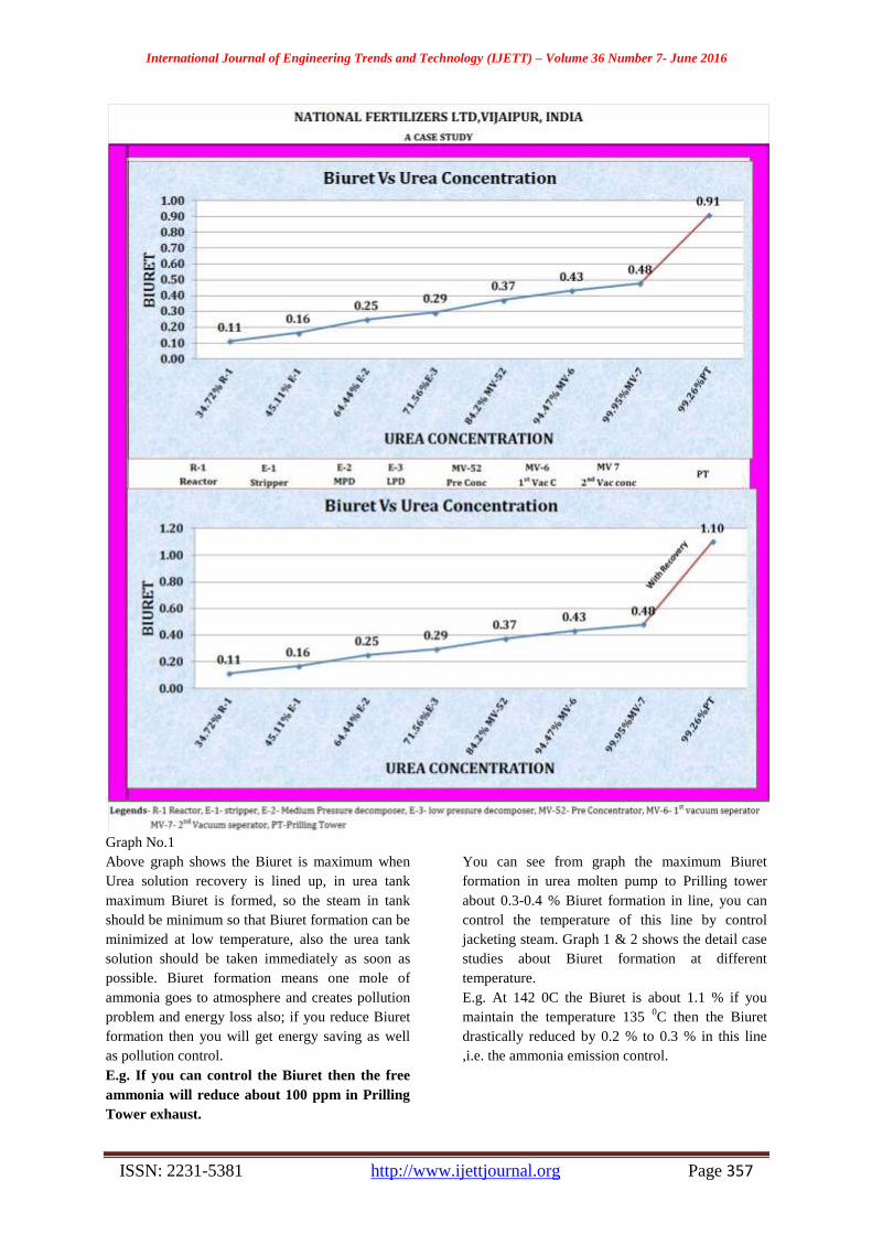
Graph No.1
Above graph shows the Biuret is maximum when
Urea solution recovery is lined up, in urea tank
maximum Biuret is formed, so the steam in tank
should be minimum so that Biuret formation can be
minimized at low temperature, also the urea tank
solution should be taken immediately as soon as
possible. Biuret formation means one mole of
ammonia goes to atmosphere and creates pollution
problem and energy loss also; if you reduce Biuret
formation then you will get energy saving as well
as pollution control.
E.g. If you can control the Biuret then the free
ammonia will reduce about 100 ppm in Prilling
Tower exhaust.
You can see from graph the maximum Biuret
formation in urea molten pump to Prilling tower
about 0.3-0.4 % Biuret formation in line, you can
control the temperature of this line by control
jacketing steam. Graph 1 & 2 shows the detail case
studies about Biuret formation at different
temperature.
E.g. At 142 0C the Biuret is about 1.1 % if you
maintain the temperature 135 0C then the Biuret
drastically reduced by 0.2 % to 0.3 % in this line
,i.e. the ammonia emission control.

International Journal of Engineering Trends and Technology (IJETT) – Volume 36 Number 7- June 2016
ISSN: 2231-5381 http://www.ijettjournal.org Page 358
Graph No.2
The above graph shows the Biuret is the function of Temperature and concentration.The controllable factor is
temperature.
International Journal of Engineering Trends and Technology (IJETT) – Volume 36 Number 7- June 2016
ISSN: 2231-5381 http://www.ijettjournal.org Page 359
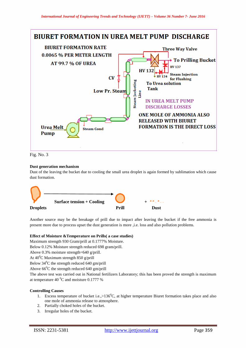
Fig. No. 3
Dust generation mechanism
Dust of the leaving the bucket due to cooling the small urea droplet is again formed by sublimation which cause
dust formation.
Surface tension + Cooling +
Droplets Prill Dust
Another source may be the breakage of prill due to impact after leaving the bucket if the free ammonia is
present more due to process upset the dust generation is more ,i.e. loss and also pollution problems.
Effect of Moisture &Temperature on Prills( a case studies)
Maximum strength 930 Gram/prill at 0.1777% Moisture.
Below 0.12% Moisture strength reduced 698 gram/prill.
Above 0.3% moisture strength=640 g/prill.
At 400C Maximum strength 850 g/prill
Below 340C the strength reduced 640 gm/prill
Above 660C the strength reduced 640 gm/prill
The above test was carried out in National fertilizers Laboratory; this has been proved the strength is maximum
at temperature 40 0C and moisture 0.1777 %
Controlling Causes
1. Excess temperature of bucket i.e.,>1360C, at higher temperature Biuret formation takes place and also
one mole of ammonia release to atmosphere.
2. Partially choked holes of the bucket.
3. Irregular holes of the bucket.
International Journal of Engineering Trends and Technology (IJETT) – Volume 36 Number 7- June 2016
ISSN: 2231-5381 http://www.ijettjournal.org Page 360
4. Overloading of plant.
5. Choking of louvers, lead to air flow restriction
6. Leakage of steam/condensate to melt line.
7. Prilling bucket overflowing due to holes chocked or less rpm of the bucket.
8. Inadequate vacuum, leading to high moisture contents.
9. Excessive pressure exerted by scrapper.
10. Dissolving of dirty urea.
Another Source of Losses.
In Urea plant lossesgenerally occurs from following sources.
1. Prilling Tower Dust & ammonia losses.(major losses & pollution contributor}
2. Losses from medium pressure vent
3. Losses from low pressure vent.
4. Losses from waste water section vent
5. Losses from urea handling area e.g. dissolving area.
6. Ammonia losses from blow down & vent stack
7. Other leakages in ammonia./Carbamate handling pumps etc.
8. Ammonia losses in floor washing basin.
9. Ammonia losses from atmospheric Tanks
(a) Urea Tank
(b) Waste water tank
(c) Tanks in vacuum sections
(d) Carbonate solution tank
Above losses are creates problem of pollution and also energy losses. These losses can be controlled, By
following method
1. Temperature of the Prilling bucket should be maintain 1340C
2. Vacuum of the both stage should be maintain as designed.
3. V-5 (urea solution tank) solution should be consumed immediately otherwise Biuret content will be
high. Biuret formation means one mole of ammonia loss)
4. Louvers opening should be maintain according as ambient condition.
5. RPM of the bucket should be maintain according to size, i.e., on the wall speed &overflow speed.
6. Visual checking of product quality on continuous basis.
7. Thorough cleaning of Prilling bucket before installation.
8. Maintaining proper vacuum in both the streams.
9. Adjusting Prilling Bucket speed based on visual
10. Checking and lab reports.
11. Regular cleaning of scrapper floor and top louvers. Flushing of vacuum condensers twice a shift for
maintaining proper vacuum. Flushing of vacuum separators on alternate days. Regular cleaning of Urea
recovery pump strainers and ensuring no bypassing in them.
12. The vacuum and temperature may be controlled as per figure No. 2.
13. The 2nd
vacuum must be controlled about 0.03 to 0.04 ata for proper concentration to avoid free
ammonia in prills and also PT exhaust. Temperature may control as per figure No. 2.

International Journal of Engineering Trends and Technology (IJETT) – Volume 36 Number 7- June 2016
ISSN: 2231-5381 http://www.ijettjournal.org Page 361
Table No.2
Above losses can be reduced by some modification in Heat exchangers & Process recently National Fertilizers
ltd. Carried out some modification as following.-

International Journal of Engineering Trends and Technology (IJETT) – Volume 36 Number 7- June 2016
ISSN: 2231-5381 http://www.ijettjournal.org Page 362
1. Modification in Heat exchanger (E-11)
Description:-
In Urea plant, C-3 off gases from medium pressure
section is being vented continuously to control the
loop pressure. Each stream of Urea Plant generates
around 700 -800 Nm³/h of C-3 off gases, so total
generation of C-3 off gases is around 2800 Nm³/h.
C-3 off gas comprises Hydrogen, Methane,
Ammonia, Nitrogen & Oxygen in the ratio of 25-
30%, 7-10%, 2.5-12%, 50-55% & 6-10%
respectively. Considering the heating value of C-3
off gases, it has been utilized these gases in HRU-I
&II as supplementary fuel. MP inerts washing tower
absorbs ammonia from it’s inlet vapour comprising
of inerts such as hydrogen, methane argon nitrogen
& oxygen in three numbers of valve trays fitted at
the top of the E-11 which is called as C-03 cold
condensate at 40 0C of about 0.5 -0.8 m
3/hr. is being
used as absorbent which is being introduced at the
top of the valve tray tower(C-3). The some amount
(30-50 sm3/hr) of natural gas feed in inlet of
medium pressure condenser (E-7) to avoid explosive
mixture in exit of control valve because the oxygen
about 8-10 % present in gases mixture.
The heat of absorption for formation of ammonical
solution is being taken out through vertically
installed cooling water exchanger E-11 for better
heat transfer by forming falling film; E-11 has been
equipped with ferrules at top having 02 numbers
tangential hole of 1.5 mm dia hole. Ammonical
solution while falling down through heat exchanger
(E-11) gets cooled after exchanger heat with cooling
water up to about 430C and recycles back into the
upstream equipment as economy of the process.
Inerts along with residual ammonia was being
vented to top of the prilling tower through 31/41 PV
108 and this removal of inerts are required to
maintain MP loop pressure at desired range. This
inerts gases along with residual ammonia is called
C-3 off gas having lower calorific value in the range
of 1500 Kcal/nm3.
Since commissioning of urea-II plant, C-3 off gas
comprising of about 4-5% of ammonia was vented
to atmosphere through prilling tower top stack
continuously with flow of about 600-800 nm3/hr.
from each stream of urea-II. In 2012 these gases had
been lined to HRU in CPP for recovers its energy.
However line-I ammonia in off gasses are 0.5-1.2
%, in line-II plant this figure is more than line-I so
the minor modification has been done to improved
efficiency of heat exchanger E-11. However since
October 2012, modification has been carried out for
utilization of C-3 off gas as supplementary fuel in
CPP HRSG burners as this gas having significant
calorific value. This modification became successful
with saving 2.8 G.cal /hr. resulted in financial
saving of `5.00 crore. Further during capacity
enhancement project of urea-II plant, process
Licenser M/S. Saipem had recommended certain
modification for the vapour inlet nozzle of 31/41 E-
11/C-3 and the same modification, vapour inlet
nozzle has been extended up to minimum bottom
level of C-3/E-11 bottom solution holder from its
original location of the equipment weld neck flange
position.
After implementation the modification proposed by
process licenser in July 2012, C-3 off gas ammonia
content reduced drastically from 4-6 to 3-5 % in
urea-II plant. Off gas is being used as supplementary
fuel in CPP HRSG burner with flow of about 600-
900 nm3/hr. from each stream with ammonia
contents of 3-6 % giving higher NOx level in the
flue gases of CPP, HRSG.
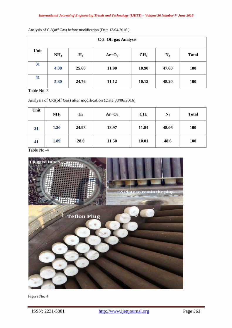
In May 2016 shut down cooling water exchanger of
MP Inerts washing tower (E-11) has been modified
by plugging about 110 peripheral tubes at top only
with press fitted Teflon plug as shown in the
attached photograph in figure No.4. Further one SS
plate has been welded to retain the press fitted plug
at its position firmly. After implementation of this
modification ammonia contents in C-3 off gas has
been come down to 1-2 % .Matter has been taken
up with M/S Saipem & process Licenser has been
agreed for proposed modification for plugging of E-
11 peripheral tubes. The water contents 0.5-0.8
m3/hr is the very less quantity within 400 tubes the
film in heat exchanger was not made, also the
sufficient hold up level up to ferrules tangential
holes on tube sheet, now the 27 % tubes has been
plugged and now no problem in heat exchanger heat
transfer.
International Journal of Engineering Trends and Technology (IJETT) – Volume 36 Number 7- June 2016
ISSN: 2231-5381 http://www.ijettjournal.org Page 363
Analysis of C-3(off Gas) before modification (Date 13/04/2016.)
C-3 Off gas Analysis
Unit NH3 H2 Ar+O2 CH4 N2 Total
31 4.00 25.60 11.90 10.90 47.60 100
41 5.80 24.76 11.12 10.12 48.20 100
Table No. 3
Analysis of C-3(off Gas) after modification (Date 08/06/2016)
Unit NH3 H2 Ar+O2 CH4 N2 Total
31 1.20 24.93 13.97 11.84 48.06 100
41 1.89 28.0 11.50 10.01 48.6 100
Table No -4
Figure No. 4
International Journal of Engineering Trends and Technology (IJETT) – Volume 36 Number 7- June 2016
ISSN: 2231-5381 http://www.ijettjournal.org Page 364
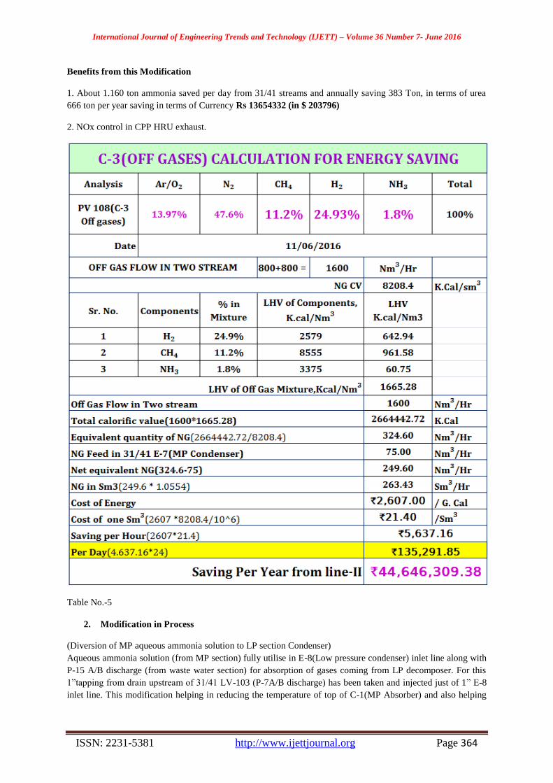
Benefits from this Modification
1. About 1.160 ton ammonia saved per day from 31/41 streams and annually saving 383 Ton, in terms of urea
666 ton per year saving in terms of Currency Rs 13654332 (in $ 203796)
2. NOx control in CPP HRU exhaust.
Table No.-5
2. Modification in Process
(Diversion of MP aqueous ammonia solution to LP section Condenser)
Aqueous ammonia solution (from MP section) fully utilise in E-8(Low pressure condenser) inlet line along with
P-15 A/B discharge (from waste water section) for absorption of gases coming from LP decomposer. For this
1”tapping from drain upstream of 31/41 LV-103 (P-7A/B discharge) has been taken and injected just of 1” E-8
inlet line. This modification helping in reducing the temperature of top of C-1(MP Absorber) and also helping

International Journal of Engineering Trends and Technology (IJETT) – Volume 36 Number 7- June 2016
ISSN: 2231-5381 http://www.ijettjournal.org Page 365
the controlling LP pressure, The cold water to C-4(low pressure inerts tower) now reduced to zero. The
modified flow diagram as shown in the figure No. -5
Figure No -5
In this modification the motor stopped and suction
/discharge lines connected to each other. The
solution transferred by differential of Low Pressure
& Medium Pressure, Pump stopped i.e. saving of
power.
Following advantages with this modification
1. Reflux to C-1(medium pressure absorber)
Reduced by 2.0 m3/hr.
2. Additional water to C-4(low pressure
inerts washing column) now fully stopped.
3. No limitation to increase the water flow to
C-3(medium pressure inerts washing
column) to minimize ammonia losses.
4. Ammonia drastically reduced in C-3
(medium pressure inerts washing column)
off gas. And NOx control in HRU exhaust.
5. Low Pressure section pressure easily
controlled and water reduced in C-4(low
pressure inerts washing column)
6. Power saving in one stream=VI Cos ø X
√3 =440 X15 X 0.9=10288 W =10.288
KWH and for both streams 2 X 10.288
KWH =20.567 KWH, Now Annually
saving 180245.8 KWH, in Currency
Rupees = Rs 901229 ($ 13665).
Conclusion
N.F.L.Vijaipur is very much committed to Energy
management. Considering that Fertilizer
manufacturing is an energy intensive process, we
have realized that a small step towards within the
premises of NFL shall be a great leap in the energy
front of the Country and shall help in materializing
the Targets. Urea prills are produced in the Prilling
towers where a solidification-cooling process takes
place. The ambient air is used as the cooling air
stream for this process. In hot days, the temperature
of the product at the bottom of the tower are hot
that cannot be packed directly. In addition, in hot/
humid days, prills form lamps and cakes with each
other and on the scrubber. The variation of average
particle temperature and moisture content is
produced along the tower height as well as for the
airside. The National Fertilizers Ltd, Vijaipur has
always made consistent Endeavour’s and efforts’
towards energy conservation and continual
International Journal of Engineering Trends and Technology (IJETT) – Volume 36 Number 7- June 2016
ISSN: 2231-5381 http://www.ijettjournal.org Page 366
improvement in the direction of energy reduction
and improvement in the direction of energy
reduction and improvement in energy efficiency.
The line-I and line-II plants have been revamped in
2012.After revamp the significant reduction of
energy have been noticed. After the
implementation of above modification in
equipments and process the significant energy has
been saved and also controls NOx in HRU exhaust
in captive power plant. Now after this modification
NOX was came down drastically in HRU exhaust.
Acknowledgement
We express sincere thanks to Mr. R.K. Chopra,
General Manager, National Fertilizers Ltd.,
Vijaipur Unit, for his support and guidance in
carrying out this modification & study.
References- The Energy saving in urea plant by
modification in Heat exchanger & Process, Author-
Prem Baboo. International Journal of Engineering
Research & Technology, Volume. 5, Issue. 06,
June – 2016.
Legends
LP- Low Pressure
MP- medium Pressure,
LS- Low pressure steam
MS- Medium Pressure Steam.
SS-Stain less steel (SS 316)
G. cal-Giga Calorie
CPP-captive power plant
HRSG-heat recovery steam generation
HRU-Heat recovery unit
INR-Indian Rupees
PT- Prilling Tower.
C-2 Distillation Tower.
**********************************************************************************


