
Energy-recovery System for Continuous Conveyors … · Energy-recovery System for ... allows an...
16
BulkEurope 2012 1 Energy-recovery System for Continuous Conveyors Dipl.-Ing. Dr.mont. Michael Prenner Univ.-Prof. Dipl.-Ing. Dr.mont. Franz Kessler Chair of Conveying Technology and Design Methods University of Leoben Franz-Josef-Straße 18 A8700 Leoben, Austria [email protected] Abstract Materials, which were transported by continuous conveying systems, have partly, depending on the speed of travel, a High - energy content. At transfer points from one conveyor to another or at discharge points from a conveyor to a storage area or to a discontinuous conveying system, it is possible to recover most of this energy and return it to the conveying system. At the chair of Conveying Systems and Design Methods at the University of Leoben an energy recovery system, which allows the recovery of a large percentage of the kinetic and the potential energy of the transported material, was developed. This energy could be returned to the conveyor in the form of electrical or mechanical power. The functional principle of the so called "Solid State Material Driven Turbine" could be already confirmed by experiments at a transfer point of a belt conveyor test rig for bulk material. Figure 1: Belt conveyor test rig with a "Solid State Material Driven Turbine" This simple test facility, which is shown in figure 1, allows an energy recovery of about 80% of the kinetic and potential energy of the bulk material. The energy is returned to the conveyor in the form of mechanical power. The experimental test results could also be confirmed by discrete element simulations (figure 2).
Transcript of Energy-recovery System for Continuous Conveyors … · Energy-recovery System for ... allows an...
BulkEurope 2012
1
Energy-recovery System for Continuous Conveyors
Dipl.-Ing. Dr.mont. Michael Prenner
Univ.-Prof. Dipl.-Ing. Dr.mont. Franz Kessler
Chair of Conveying Technology and Design Methods
University of Leoben
Franz-Josef-Straße 18
A8700 Leoben, Austria
Abstract
Materials, which were transported by continuous conveying systems, have partly, depending on the speed of travel, a
High - energy content. At transfer points from one conveyor to another or at discharge points from a conveyor to a storage
area or to a discontinuous conveying system, it is possible to recover most of this energy and return it to the conveying
system.
At the chair of Conveying Systems and Design Methods at the University of Leoben an energy recovery system, which
allows the recovery of a large percentage of the kinetic and the potential energy of the transported material, was developed.
This energy could be returned to the conveyor in the form of electrical or mechanical power.
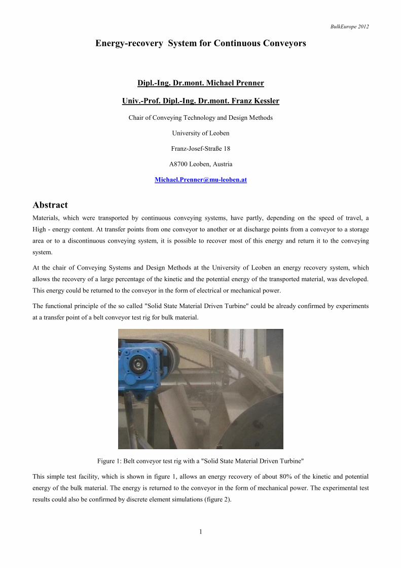
The functional principle of the so called "Solid State Material Driven Turbine" could be already confirmed by experiments
at a transfer point of a belt conveyor test rig for bulk material.
Figure 1: Belt conveyor test rig with a "Solid State Material Driven Turbine"
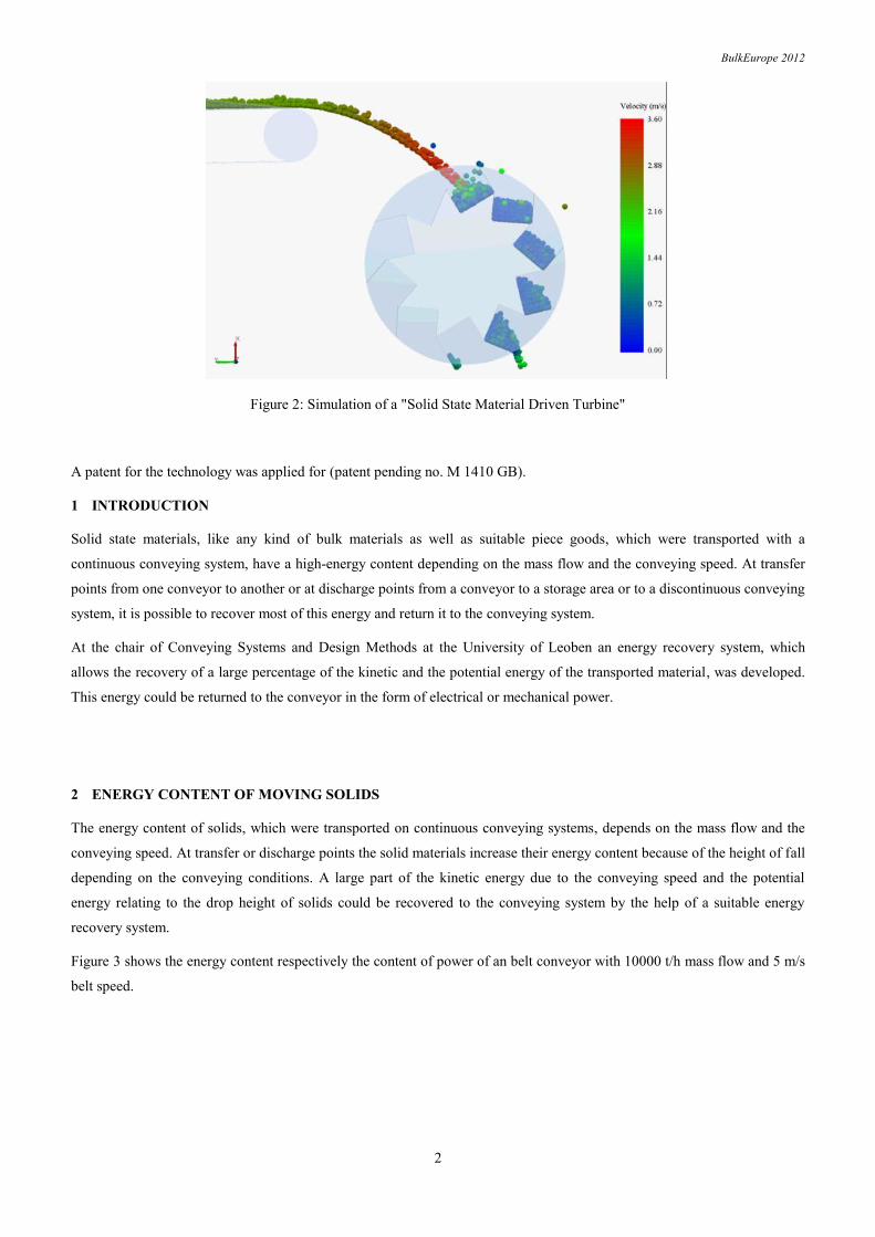
This simple test facility, which is shown in figure 1, allows an energy recovery of about 80% of the kinetic and potential
energy of the bulk material. The energy is returned to the conveyor in the form of mechanical power. The experimental test
results could also be confirmed by discrete element simulations (figure 2).
BulkEurope 2012
2
Figure 2: Simulation of a "Solid State Material Driven Turbine"
A patent for the technology was applied for (patent pending no. M 1410 GB).
1 INTRODUCTION
Solid state materials, like any kind of bulk materials as well as suitable piece goods, which were transported with a
continuous conveying system, have a high-energy content depending on the mass flow and the conveying speed. At transfer
points from one conveyor to another or at discharge points from a conveyor to a storage area or to a discontinuous conveying
system, it is possible to recover most of this energy and return it to the conveying system.
At the chair of Conveying Systems and Design Methods at the University of Leoben an energy recovery system, which
allows the recovery of a large percentage of the kinetic and the potential energy of the transported material, was developed.
This energy could be returned to the conveyor in the form of electrical or mechanical power.
2 ENERGY CONTENT OF MOVING SOLIDS
The energy content of solids, which were transported on continuous conveying systems, depends on the mass flow and the
conveying speed. At transfer or discharge points the solid materials increase their energy content because of the height of fall
depending on the conveying conditions. A large part of the kinetic energy due to the conveying speed and the potential
energy relating to the drop height of solids could be recovered to the conveying system by the help of a suitable energy
recovery system.
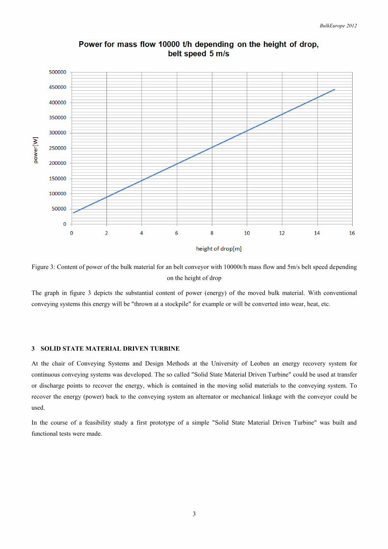
Figure 3 shows the energy content respectively the content of power of an belt conveyor with 10000 t/h mass flow and 5 m/s
belt speed.
BulkEurope 2012
3
Figure 3: Content of power of the bulk material for an belt conveyor with 10000t/h mass flow and 5m/s belt speed depending
on the height of drop
The graph in figure 3 depicts the substantial content of power (energy) of the moved bulk material. With conventional
conveying systems this energy will be "thrown at a stockpile" for example or will be converted into wear, heat, etc.
3 SOLID STATE MATERIAL DRIVEN TURBINE
At the chair of Conveying Systems and Design Methods at the University of Leoben an energy recovery system for
continuous conveying systems was developed. The so called "Solid State Material Driven Turbine" could be used at transfer
or discharge points to recover the energy, which is contained in the moving solid materials to the conveying system. To
recover the energy (power) back to the conveying system an alternator or mechanical linkage with the conveyor could be
used.
In the course of a feasibility study a first prototype of a simple "Solid State Material Driven Turbine" was built and
functional tests were made.
BulkEurope 2012
4
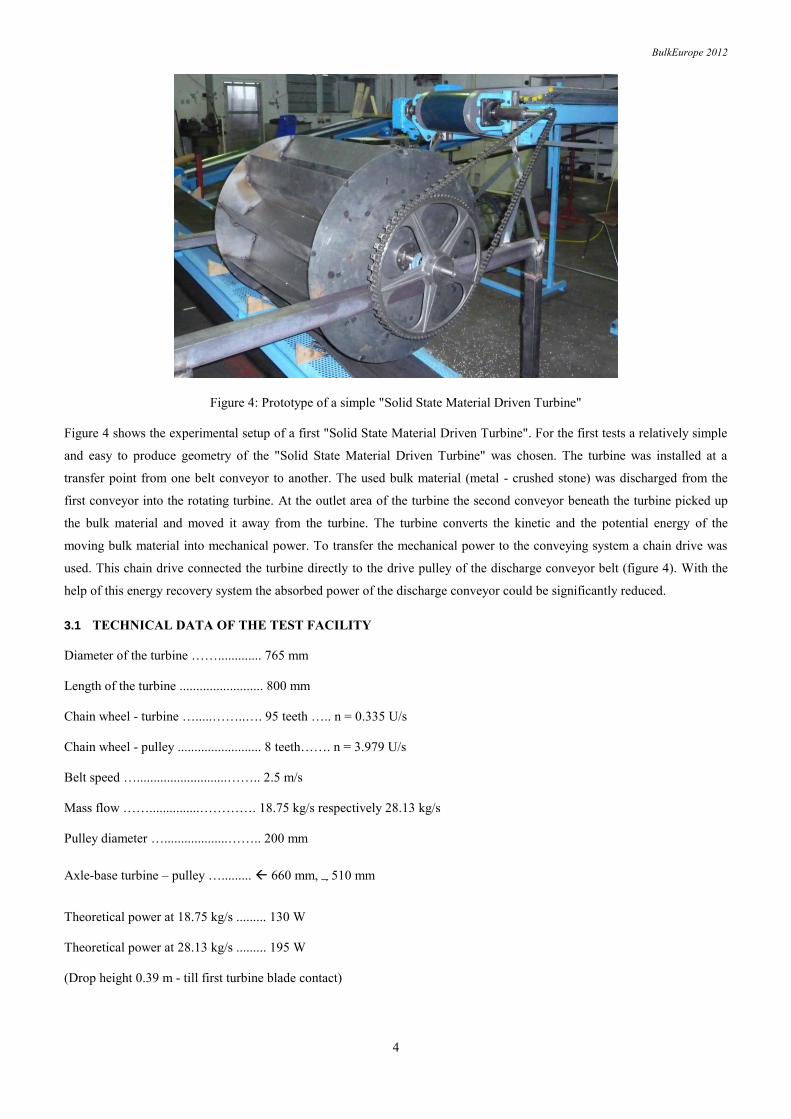
Figure 4: Prototype of a simple "Solid State Material Driven Turbine"
Figure 4 shows the experimental setup of a first "Solid State Material Driven Turbine". For the first tests a relatively simple
and easy to produce geometry of the "Solid State Material Driven Turbine" was chosen. The turbine was installed at a
transfer point from one belt conveyor to another. The used bulk material (metal - crushed stone) was discharged from the
first conveyor into the rotating turbine. At the outlet area of the turbine the second conveyor beneath the turbine picked up
the bulk material and moved it away from the turbine. The turbine converts the kinetic and the potential energy of the
moving bulk material into mechanical power. To transfer the mechanical power to the conveying system a chain drive was
used. This chain drive connected the turbine directly to the drive pulley of the discharge conveyor belt (figure 4). With the
help of this energy recovery system the absorbed power of the discharge conveyor could be significantly reduced.
3.1 TECHNICAL DATA OF THE TEST FACILITY
Diameter of the turbine ……............. 765 mm
Length of the turbine ......................... 800 mm
Chain wheel - turbine ….....……..…. 95 teeth ….. n = 0.335 U/s
Chain wheel - pulley ......................... 8 teeth……. n = 3.979 U/s
Belt speed …...........................…….. 2.5 m/s
Mass flow ……...............…………. 18.75 kg/s respectively 28.13 kg/s
Pulley diameter …...................…….. 200 mm
Axle-base turbine – pulley …......... 660 mm, 510 mm
Theoretical power at 18.75 kg/s ......... 130 W
Theoretical power at 28.13 kg/s ......... 195 W
(Drop height 0.39 m - till first turbine blade contact)
BulkEurope 2012
5
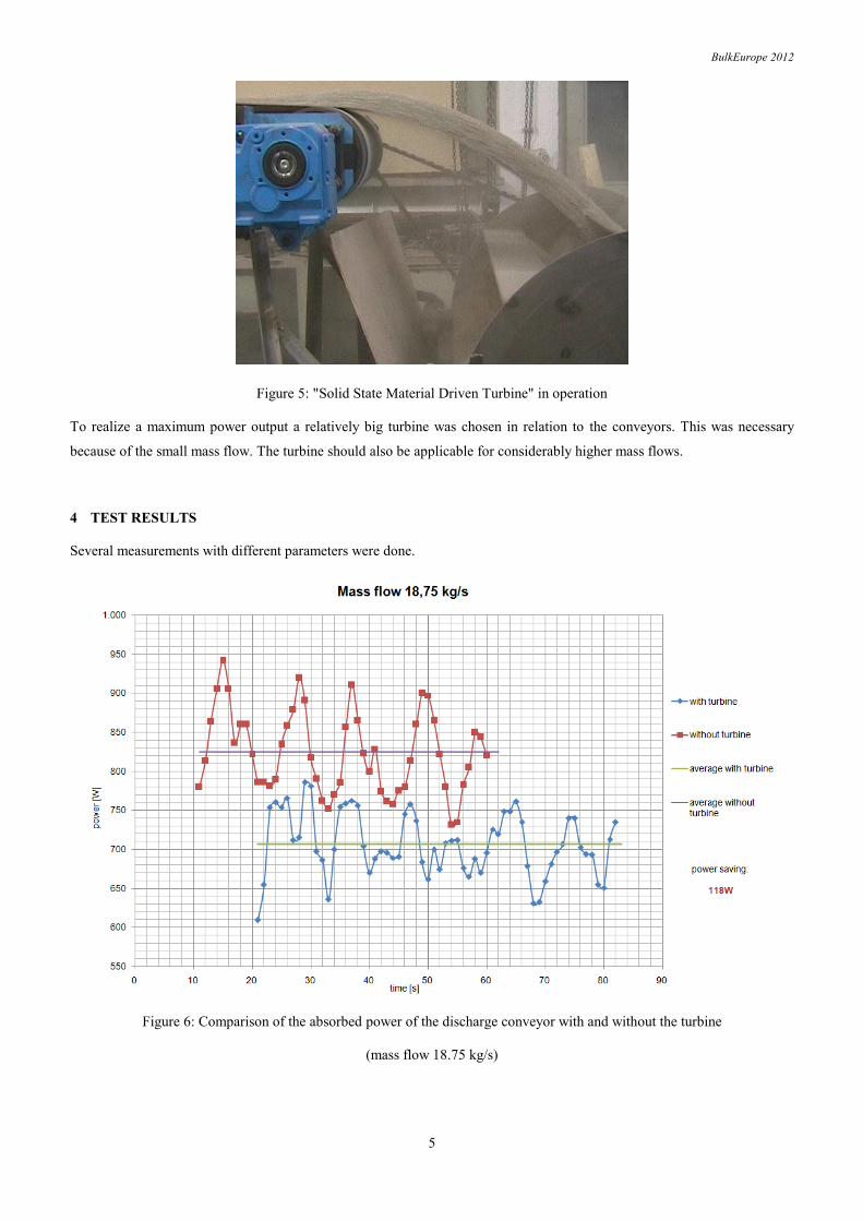
Figure 5: "Solid State Material Driven Turbine" in operation
To realize a maximum power output a relatively big turbine was chosen in relation to the conveyors. This was necessary
because of the small mass flow. The turbine should also be applicable for considerably higher mass flows.
4 TEST RESULTS
Several measurements with different parameters were done.
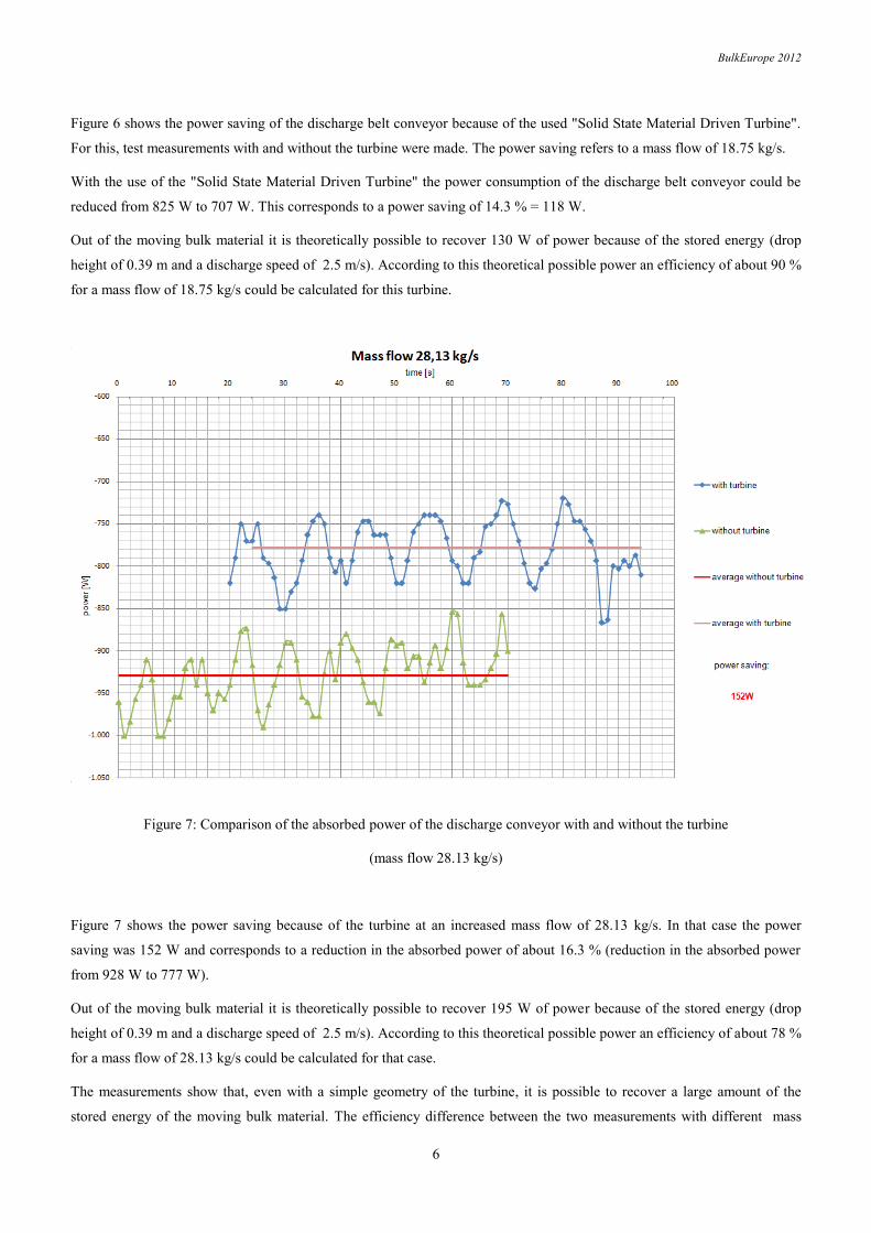
Figure 6: Comparison of the absorbed power of the discharge conveyor with and without the turbine
(mass flow 18.75 kg/s)
BulkEurope 2012
6
Figure 6 shows the power saving of the discharge belt conveyor because of the used "Solid State Material Driven Turbine".
For this, test measurements with and without the turbine were made. The power saving refers to a mass flow of 18.75 kg/s.
With the use of the "Solid State Material Driven Turbine" the power consumption of the discharge belt conveyor could be
reduced from 825 W to 707 W. This corresponds to a power saving of 14.3 % = 118 W.
Out of the moving bulk material it is theoretically possible to recover 130 W of power because of the stored energy (drop
height of 0.39 m and a discharge speed of 2.5 m/s). According to this theoretical possible power an efficiency of about 90 %
for a mass flow of 18.75 kg/s could be calculated for this turbine.
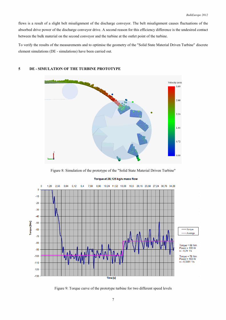
Figure 7: Comparison of the absorbed power of the discharge conveyor with and without the turbine
(mass flow 28.13 kg/s)
Figure 7 shows the power saving because of the turbine at an increased mass flow of 28.13 kg/s. In that case the power
saving was 152 W and corresponds to a reduction in the absorbed power of about 16.3 % (reduction in the absorbed power
from 928 W to 777 W).
Out of the moving bulk material it is theoretically possible to recover 195 W of power because of the stored energy (drop
height of 0.39 m and a discharge speed of 2.5 m/s). According to this theoretical possible power an efficiency of about 78 %
for a mass flow of 28.13 kg/s could be calculated for that case.
The measurements show that, even with a simple geometry of the turbine, it is possible to recover a large amount of the
stored energy of the moving bulk material. The efficiency difference between the two measurements with different mass
BulkEurope 2012
7
flews is a result of a slight belt misalignment of the discharge conveyor. The belt misalignment causes fluctuations of the
absorbed drive power of the discharge conveyor drive. A second reason for this efficiency difference is the undesired contact
between the bulk material on the second conveyor and the turbine at the outlet point of the turbine.
To verify the results of the measurements and to optimise the geometry of the "Solid State Material Driven Turbine" discrete
element simulations (DE - simulations) have been carried out.
5 DE - SIMULATION OF THE TURBINE PROTOTYPE
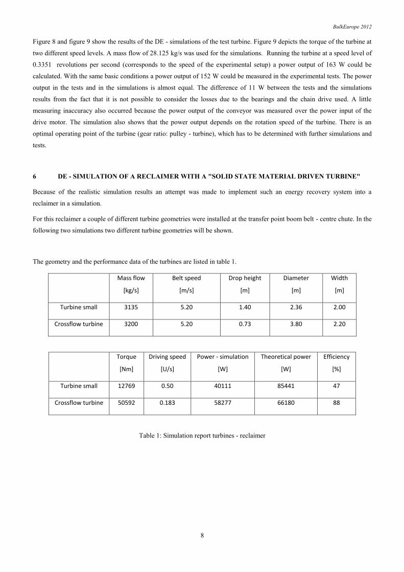
Figure 8: Simulation of the prototype of the "Solid State Material Driven Turbine"
Figure 9: Torque curve of the prototype turbine for two different speed levels
BulkEurope 2012
8
Figure 8 and figure 9 show the results of the DE - simulations of the test turbine. Figure 9 depicts the torque of the turbine at
two different speed levels. A mass flow of 28.125 kg/s was used for the simulations. Running the turbine at a speed level of
0.3351 revolutions per second (corresponds to the speed of the experimental setup) a power output of 163 W could be
calculated. With the same basic conditions a power output of 152 W could be measured in the experimental tests. The power
output in the tests and in the simulations is almost equal. The difference of 11 W between the tests and the simulations
results from the fact that it is not possible to consider the losses due to the bearings and the chain drive used. A little
measuring inaccuracy also occurred because the power output of the conveyor was measured over the power input of the
drive motor. The simulation also shows that the power output depends on the rotation speed of the turbine. There is an
optimal operating point of the turbine (gear ratio: pulley - turbine), which has to be determined with further simulations and
tests.
6 DE - SIMULATION OF A RECLAIMER WITH A "SOLID STATE MATERIAL DRIVEN TURBINE"
Because of the realistic simulation results an attempt was made to implement such an energy recovery system into a
reclaimer in a simulation.
For this reclaimer a couple of different turbine geometries were installed at the transfer point boom belt - centre chute. In the
following two simulations two different turbine geometries will be shown.
The geometry and the performance data of the turbines are listed in table 1.
Mass flow
[kg/s]
Belt speed
[m/s]
Drop height
[m]
Diameter
[m]
Width
[m]
Turbine small 3135 5.20 1.40 2.36 2.00
Crossflow turbine 3200 5.20 0.73 3.80 2.20
Torque
[Nm]
Driving speed
[U/s]
Power - simulation
[W]
Theoretical power
[W]
Efficiency
[%]
Turbine small 12769 0.50 40111 85441 47
Crossflow turbine 50592 0.183 58277 66180 88
Table 1: Simulation report turbines - reclaimer
BulkEurope 2012
9
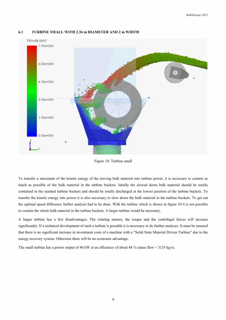
6.1 TURBINE SMALL WITH 2.36 m DIAMETER AND 2 m WIDTH
Figure 10: Turbine small
To transfer a maximum of the kinetic energy of the moving bulk material into turbine power, it is necessary to contain as
much as possible of the bulk material in the turbine buckets. Ideally the slowed down bulk material should be totally
contained in the mashed turbine buckets and should be totally discharged at the lowest position of the turbine buckets. To
transfer the kinetic energy into power it is also necessary to slow down the bulk material in the turbine buckets. To get out
the optimal speed difference further analysis had to be done. With the turbine which is shown in figure 10 it is not possible
to contain the whole bulk material in the turbine buckets. A larger turbine would be necessary.
A larger turbine has a few disadvantages. The rotating masses, the torque and the centrifugal forces will increase
significantly. If a technical development of such a turbine is possible it is necessary to do further analyses. It must be ensured
that there is no significant increase in investment costs of a machine with a "Solid State Material Driven Turbine" due to the
energy recovery system. Otherwise there will be no economic advantage.
The small turbine has a power output of 40 kW at an efficiency of about 48 % (mass flew = 3135 kg/s).
BulkEurope 2012
10
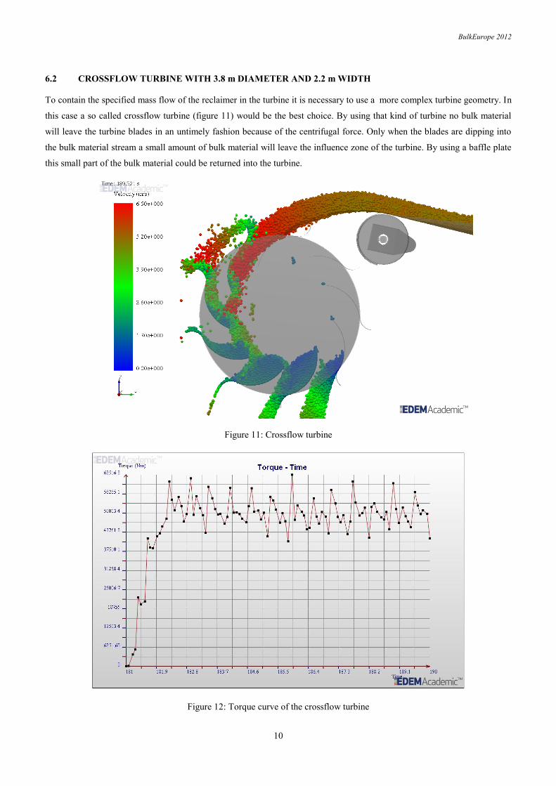
6.2 CROSSFLOW TURBINE WITH 3.8 m DIAMETER AND 2.2 m WIDTH
To contain the specified mass flow of the reclaimer in the turbine it is necessary to use a more complex turbine geometry. In
this case a so called crossflow turbine (figure 11) would be the best choice. By using that kind of turbine no bulk material
will leave the turbine blades in an untimely fashion because of the centrifugal force. Only when the blades are dipping into
the bulk material stream a small amount of bulk material will leave the influence zone of the turbine. By using a baffle plate
this small part of the bulk material could be returned into the turbine.
Figure 11: Crossflow turbine
Figure 12: Torque curve of the crossflow turbine
BulkEurope 2012
11
7 IMPLEMENTING A "SOLID STATE MATERIAL DRIVEN TURBINE" IN AN EXISTING CONVEYOR
To test the function of such an energy recovery system in practice a "Solid State Material Driven Turbine" will be installed
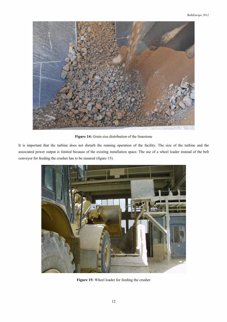
at a facility in the area of limestone in Austria. The operating conditions in this case are relatively critical. The bulk material
(limestone) has a grain size distribution between 10 % < 10 mm and 10 % > 70 mm with a maximum particle size of 300
mm (figure 14). For this kind of bulk material, critical wear conditions at the turbine should be expected. Furthermore, fine
material could stick in the turbine buckets. This could also affect the function of the turbine. These critical conditions should
give more insight into the limits of application of such an energy recovery system.
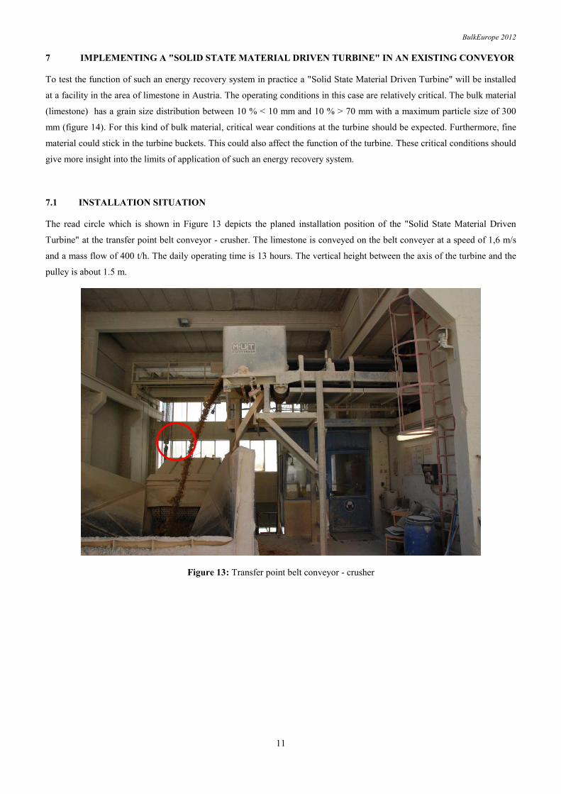
7.1 INSTALLATION SITUATION
The read circle which is shown in Figure 13 depicts the planed installation position of the "Solid State Material Driven
Turbine" at the transfer point belt conveyor - crusher. The limestone is conveyed on the belt conveyer at a speed of 1,6 m/s
and a mass flow of 400 t/h. The daily operating time is 13 hours. The vertical height between the axis of the turbine and the
pulley is about 1.5 m.
Figure 13: Transfer point belt conveyor - crusher
BulkEurope 2012
12
Figure 14: Grain size distribution of the limestone
It is important that the turbine does not disturb the running operation of the facility. The size of the turbine and the
associated power output is limited because of the existing installation space. The use of a wheel loader instead of the belt
conveyor for feeding the crusher has to be ensured (figure 15).
Figure 15: Wheel loader for feeding the crusher
BulkEurope 2012
13
7.2 DE - SIMULATION OF THE "LIMESTONE TURBINE"
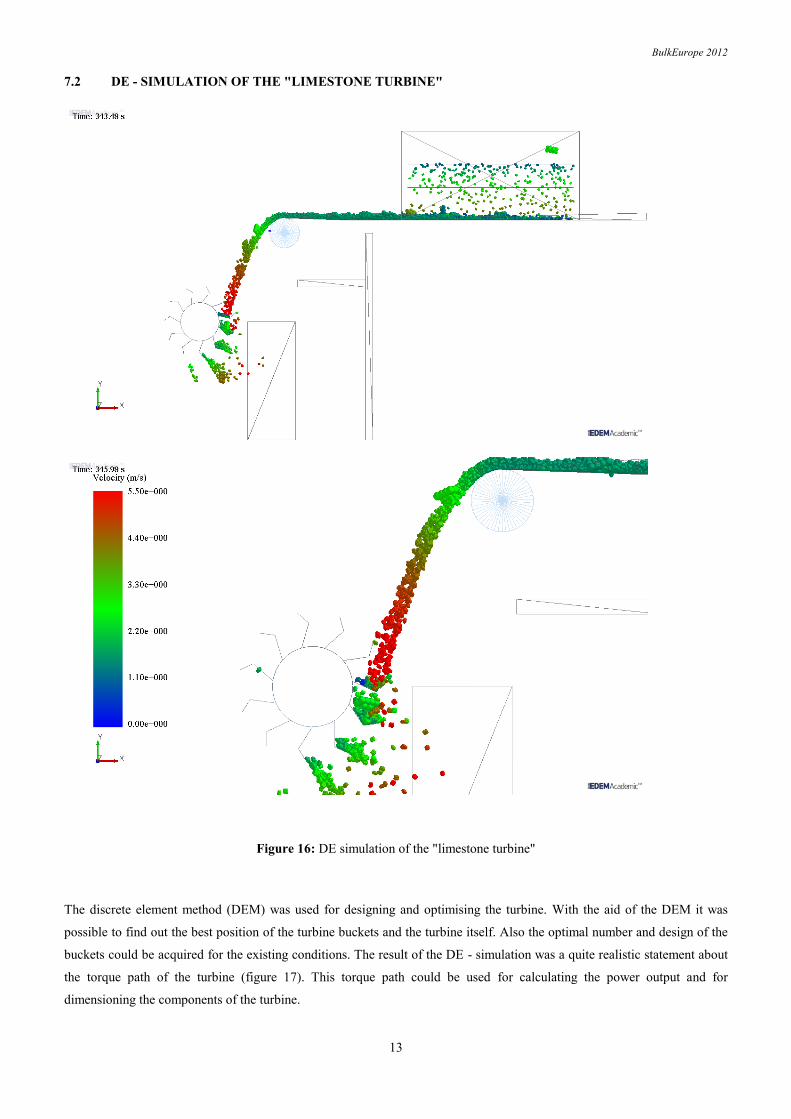
Figure 16: DE simulation of the "limestone turbine"
The discrete element method (DEM) was used for designing and optimising the turbine. With the aid of the DEM it was
possible to find out the best position of the turbine buckets and the turbine itself. Also the optimal number and design of the
buckets could be acquired for the existing conditions. The result of the DE - simulation was a quite realistic statement about
the torque path of the turbine (figure 17). This torque path could be used for calculating the power output and for
dimensioning the components of the turbine.
BulkEurope 2012
14
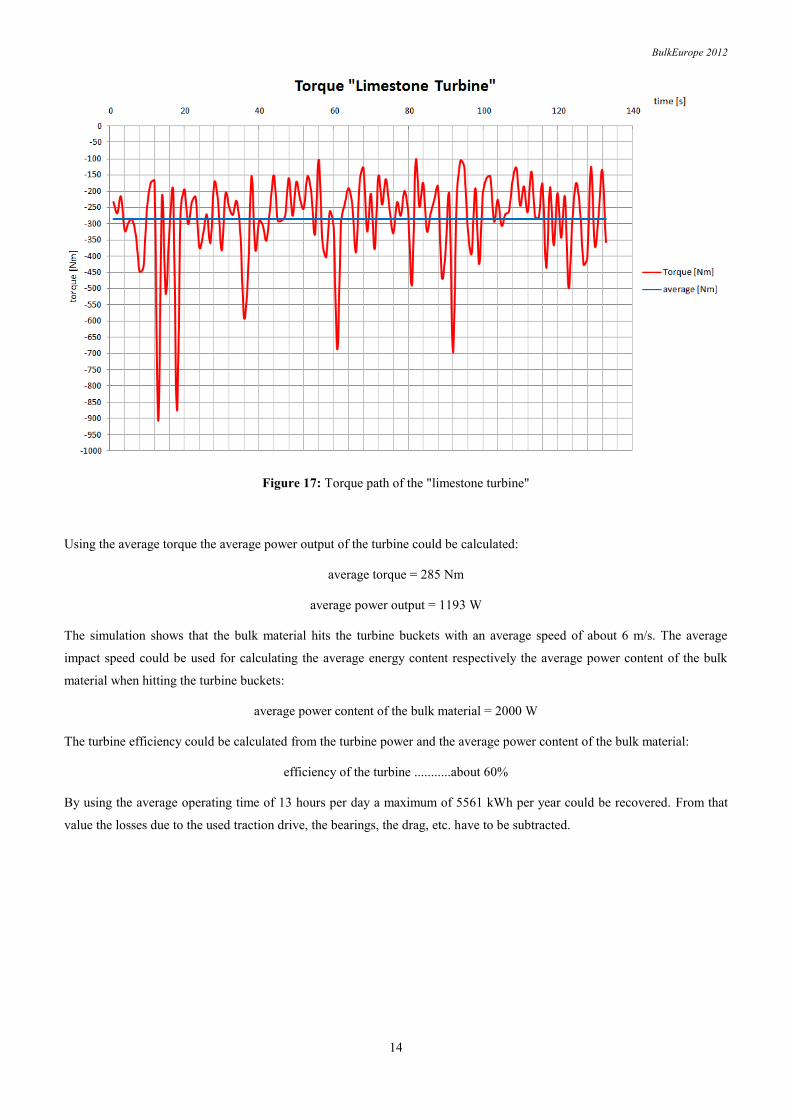
Figure 17: Torque path of the "limestone turbine"
Using the average torque the average power output of the turbine could be calculated:
average torque = 285 Nm
average power output = 1193 W
The simulation shows that the bulk material hits the turbine buckets with an average speed of about 6 m/s. The average
impact speed could be used for calculating the average energy content respectively the average power content of the bulk
material when hitting the turbine buckets:
average power content of the bulk material = 2000 W
The turbine efficiency could be calculated from the turbine power and the average power content of the bulk material:
efficiency of the turbine ...........about 60%
By using the average operating time of 13 hours per day a maximum of 5561 kWh per year could be recovered. From that
value the losses due to the used traction drive, the bearings, the drag, etc. have to be subtracted.
BulkEurope 2012
15
7.3 DESIGN OF THE "LIMESTONE TURBINE"
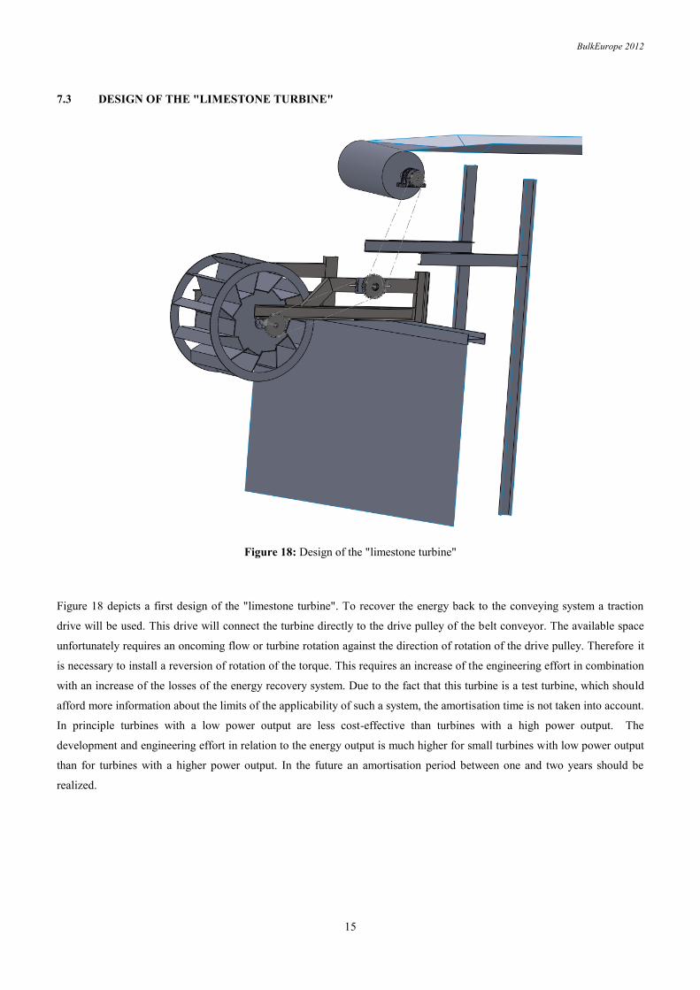
Figure 18: Design of the "limestone turbine"
Figure 18 depicts a first design of the "limestone turbine". To recover the energy back to the conveying system a traction
drive will be used. This drive will connect the turbine directly to the drive pulley of the belt conveyor. The available space
unfortunately requires an oncoming flow or turbine rotation against the direction of rotation of the drive pulley. Therefore it
is necessary to install a reversion of rotation of the torque. This requires an increase of the engineering effort in combination
with an increase of the losses of the energy recovery system. Due to the fact that this turbine is a test turbine, which should
afford more information about the limits of the applicability of such a system, the amortisation time is not taken into account.
In principle turbines with a low power output are less cost-effective than turbines with a high power output. The
development and engineering effort in relation to the energy output is much higher for small turbines with low power output
than for turbines with a higher power output. In the future an amortisation period between one and two years should be
realized.
BulkEurope 2012
16
8 CONCLUSION
First tests have confirmed that it is possible to recover energy from moving bulk materials. The so called "Solid State
Material Driven Turbine" could be used at discharge or transfer points to recover this energy, for example, to the conveying
system. It is possible to realize a high effectiveness with a relatively simple turbine geometry. For an efficient use of that
kind of technology it is necessary to use simple geometries and constructions. The turbine buckets are exposed to strong
wear depending on the bulk material used and have to be lined with removable wear plates. This is much easier and more
economic if the geometry of the turbine buckets is simple.
The "limestone turbine" is currently under construction and should show the wear behaviour of the turbine in a long-duration
test. Based on this test a "Solid State Material Driven Turbine" with a power output of more than 40 kW should be
developed and tested.
In the field of conveying technologies it is also important to act in an efficient manner. The described technology could make
a small contribution to reduce the energy consumption of conveying systems. In this case the energy which could be
recovered is freely available. At the present time this energy is thrown onto a stockpile or is converted into plant wear.


