![Untitled-4 [] · Standard lamineret (8 meter / *4 meter) Neon lamineret - 5 meter Mat lamineret - 8 meter / **5 meter) Metallic lamineret - 8 meter Ulamineret - 8 meter Fleksibel](https://static.fdocuments.net/doc/165x107/5f3a768af7b8e86a6437cff7/untitled-4-standard-lamineret-8-meter-4-meter-neon-lamineret-5-meter.jpg)
Energy Meter - davidsonsalesshop.com A20... · Hoyt Electrical Instrument Works Inc. Phone: (800)...
3
Hoyt Electrical Instrument Works Inc. Phone: (800) 258-3652 www.hoytmeter.com 23 Meter Street Fax: (603) 753-9592 H151111 Penacook, NH 03303 Email: [email protected] Page 1 of 3 DIRIS A20 Energy Meter DIRIS ® A20 Product presentation 5 4 3 2 1 Using electrical parameters means using several analog or digital single-function products such as ammeters, voltmeters or watt meters . DIRIS A20, with its four direct access keys and LCD displays, helps you use all the parameters in an LV installation. These parameters can be centralized on a PC or PLC through an RS 485 link using JBUS/MODBUS protocol. The casing is designed so that the installer To facilitate and optimize the operator’s work, the DIRIS A20 uses one of the most functional principles for integrating communications or metering. a function . In addition, DIRIS A20 has a function for correcting connection errors . 1. LCD display 2. Direct access key for instantaneous and max. currents values 3. Direct access key for voltages and frequency 4. Direct access key for active, reactive and apparent power (instantaneous and max . values) and power factor 5. Direct access key for energies Select a DIRIS ® r e b m u n g o l a t a C s U y l p p u s r e w o p y r a i l i x u A 110 … 400 VAC / 120 … 350 VDC (Product Limits) 110 ... 240 V DC / 120 ... 250 V DC (UL Approved) Select a module Description Catalog number Pulse output 4825 0080 1 Communication 4825 0082 RS 485 link with JBUS/MODBUS protocol (speed up to 38 400 bauds) DIRIS ® A20 Optional functions 4825 0A20
Transcript of Energy Meter - davidsonsalesshop.com A20... · Hoyt Electrical Instrument Works Inc. Phone: (800)...

Hoyt Electrical Instrument Works Inc. Phone: (800) 258-3652 www.hoytmeter.com23 Meter Street Fax: (603) 753-9592 H151111Penacook, NH 03303 Email: [email protected] Page 1 of 3
DIRIS A20Energy Meter
DIRIS ® A2 0Product presentation
54321
Using electrical parameters means using several analog or digital single-function products such as ammeters, voltmeters or watt meters.DIRIS A20, with its four direct access keys and LCD displays, helps you use all the parameters in an LV installation.These parameters can be centralized on a PC or PLC through an RS 485 link using JBUS/MODBUS protocol. The casing is designed so that the installer
To facilitate and optimize the operator’s work, the DIRIS A20 uses one of the most functional principles for integrating communications or metering.
a function .In addition, DIRIS A20 has a function for correcting connection errors .
1. LCD display
2. Direct access key for instantaneous and max. currents values
3. Direct access key for voltages and frequency
4. Direct access key for active, reactive and apparent power (instantaneous and max .values) and power factor
5. Direct access key for energies
Select a DIRIS®
rebmun golataCsU ylppus rewop yrailixuA
110 … 400 VAC / 120 … 350 VDC (Product Limits) 110 ... 240 V DC / 120 ... 250 V DC (UL Approved)
Select a moduleDescription Catalog number
Pulse output 4825 00801Communication 4825 0082RS 485 link with JBUS/MODBUS protocol (speed up to 38 400 bauds)
DIRIS ® A 2 0
Optional functions
4825 0A20
Hoyt Electrical Instrument Works Inc. Phone: (800) 258-3652 www.hoytmeter.com23 Meter Street Fax: (603) 753-9592 H151111Penacook, NH 03303 Email: [email protected] Page 2 of 3
DIRIS A20Energy Meter
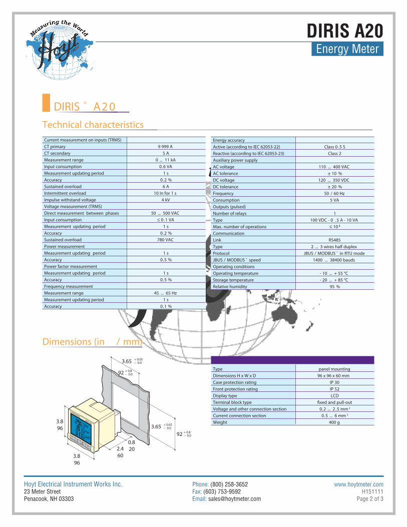
Technical characteristicsEnergy accuracyActive (according to IEC 62053-22) Class 0 .5 SReactive (according to IEC 62053-23) Class 2Auxiliary power supply
...011egatlov CA 400 VAC%01 ±ecnarelot CA
CDV 053 ...021egatlov CD%02 ±ecnarelot CD
zH 06/05ycneuqerFAV 5noitpmusnoC
Outputs (pulsed)1syaler fo rebmuN
AV 01 - A 5.0 - CDV 001epyTMax. number of operations ≤ 10 8
Communication584SRkniL
xelpud flah seriw 3 ...2epyTSUBDOM/SUBJlocotorP ® in RTU mode
JBUS / MODBUS ® sduab 00483 ...0041deeps Operating conditions
-erutarepmet gnitarepO 10 ... + 55 °CC° 58 + ... 02 -erutarepmet egarotS
%59ytidimuh evitaleR
Current measurement on inputs (TRMS)A 999 9yramirp TC
A 5yradnoces TCAk 11 ...0egnar tnemerusaeM
AV 6.0noitpmusnoc tupnIs 1doirep gnitadpu tnemerusaeM%2.0ycaruccA
A 6daolrevo deniatsuSs 1 rof nI 01daolrevo tnettimretnI
Vk 4egatlov dnatshtiw eslupmIVoltage measurement (TRMS)Direct measurement between phases 50 ... 500 VACInput consumption ≤ 0 .1 VAMeasurement updating s 1doirep
%2.0ycaruccACAV 087daolrevo deniatsuS
Power measurementMeasurement updating period 1 s
%5.0ycaruccAPower factor measurementMeasurement updating period 1 s
%5.0ycaruccAFrequency measurement
...54egnar tnemerusaeM 65 Hzs 1doirep gnitadpu tnemerusaeM%1.0ycaruccA
DIRIS ® A2 0
Dimensions (in / mm)
gnitnuom lenapepyTmm 06 x 69 x 69D x W x H snoisnemiD
03 PIgnitar noitcetorp esaC25 PIgnitar noitcetorp tnorF
DCLepyt yalpsiD
Voltage and other connection section 0.2 ... 2 .5 mm 2
mm 6 ...5.0noitces noitcennoc tnerruC 2
g 004thgieW3.896
3.896
2.460
0.820
3.65 + 0.05- 0.0
3.65 + 0.05- 0.0
92 + 0.8- 0.0
92 + 0.8- 0.0

Hoyt Electrical Instrument Works Inc. Phone: (800) 258-3652 www.hoytmeter.com23 Meter Street Fax: (603) 753-9592 H151111Penacook, NH 03303 Email: [email protected] Page 3 of 3
DIRIS A20Energy Meter
DIRIS ® A2 0Terminal blocks
DIRIS A20
A U XV3 VNV1 V2
I3I2I1
1S 2S1S 2S1S 2S
Connections
S1 - S2: current inputsAUX: auxiliary power supply UsV1, V2, V3 & VN: voltage inputs
RS485 linkR = 120 W: internal resistance for the RS485 link
Communication module
0 V - +
R = 120 ΩRS485
0n1
DIRIS A20
Low voltage balanced network
18 - 19: pulse output no . 1
Pulse output module
1 8 19
DIRIS A20OUT 1
Recommendation: when disconnecting the DIRIS, the secondaries of each current transformer must be short-circuited. This operation can be carried out automatically from a product in the SOCOMEC catalogue, PTI: please consult us.
V1 V2 V3 VN
S2
P1
S1
NL1L2L3
I3I2I1
1S 2S1S 2S1S 2S
= 0.5 A class CC1
1 1 1
• 3/4 wires with 1 CT
V1 V2 V3 VN
S2
P1
S1L1N
I3I2I1
1S 2S1S 2S1S 2S
1
1
= 0.5 A class CC
• Single phase
V1 V2 V3 VN
S2
P1
S1L1L2
I3I2I1
1S 2S1S 2S1S 2S
1
1 1
= 0.5 A class CC
• Two phases
Low voltage unbalanced network
NL1L2L3
S2
S2
P1
S1
P1
S1
V1 V2 V3 VN
I3I2I1
1S 2S1S 2S1S 2S
1
1 1 1
= 0.5 A class CC
• 3/4 wires with 3 CTs
L1L2L3
S2
S2
P1
S1
P1
S1
V1 V2 V3 VN
I3I2I1
1S 2S1S 2S1S 2S
1
1 1 1
= 0.5 A class CC
• 3 wires with 2 CTs
L1L2L3
S2
P1
S1
P1
S1
V1 V2 V3 VN
I3I2I1
1S 2S1S 2S1S 2S
1
1 1 1
= 0.5 A class CC
• 3 wires with 2 CTs
Other information
RS485
0 V - +
R = 120 ON
LIYCY-CY
• Communication via RS485 link
A U X
110 / 400 VAC120 / 350 VDC
= 0.5 A class CC
1 1
1
• AC & DC auxiliary power supply
It is recommended that the auxiliary power supply be protected by the use of 0 .5 A class CC fuses .
The use of 1 CT reduces by 0 .5 % the accuracy of the phases whose current is determined by vector calculation .
The use of 2 CTs reduces by 0 .5 % the accuracy of the phase whose current is determined by vector calculation .
The use of 2 CTs reduces by 0 .5 % the accuracy of the phase whose current is determined by vector calculation .