Energy Management System for Telecom Tower Management System for Telecom Tower (NEDO Demonstration...
21
Energy Management System for Telecom Tower (NEDO Demonstration Project in India) 29 th April, 2015 NEC Corporation
Transcript of Energy Management System for Telecom Tower Management System for Telecom Tower (NEDO Demonstration...

Energy Management System
for
Telecom Tower
(NEDO Demonstration Project in India)
29th April, 2015
NEC Corporation
Page 2 © NEC Corporation 2015
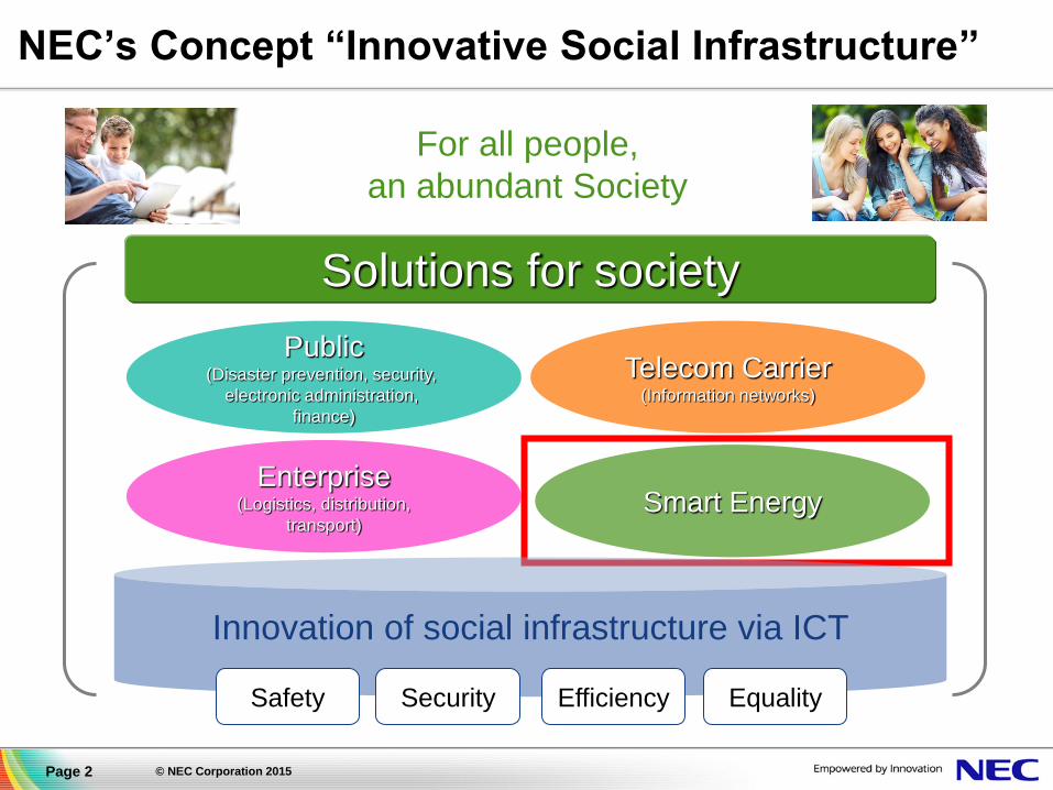
NEC’s Concept “Innovative Social Infrastructure”
Security Safety Efficiency Equality
For all people,
an abundant Society
Telecom Carrier (Information networks)
Public (Disaster prevention, security,
electronic administration,
finance)
Enterprise (Logistics, distribution,
transport) Smart Energy
Solutions for society
Innovation of social infrastructure via ICT

Page 3 © NEC Corporation 2015
Social Value Innovations by Smart Energy Business
Safety Protect the safety by
ensuring minimum power
required for disaster
Security Support safe life by stable
power supply connecting
with renewables and
other sources
Efficiency Utilize power effectively
by supply and demand
prediction and control
with high accuracy
Equality Create society where all
people can use energy
equally from downtown to
isolated islands
Contribute to realize an energy society friendly to humans and the earth by
providing solution with combination of state-of-art ICT and energy products
Energy
Products ICT
Energy Management System
(Energy Cloud)
Telecom carriers Utilities
Public
Buildings (BEMS)
Home (HEMS) Store (SEMS)
Next generation
service station
(EV Charging)
Information Electricity

Page 4 © NEC Corporation 2015
Growth of Renewable Energy in India
http://www.ey.com/Publication/vwLUAssets/Mapping_Indias_Renewable_Energy_growth_potential/$FILE/EY-Mapping-Indias-Renewable-Energy-growth-potential.pdf
Page 5 © NEC Corporation 2015
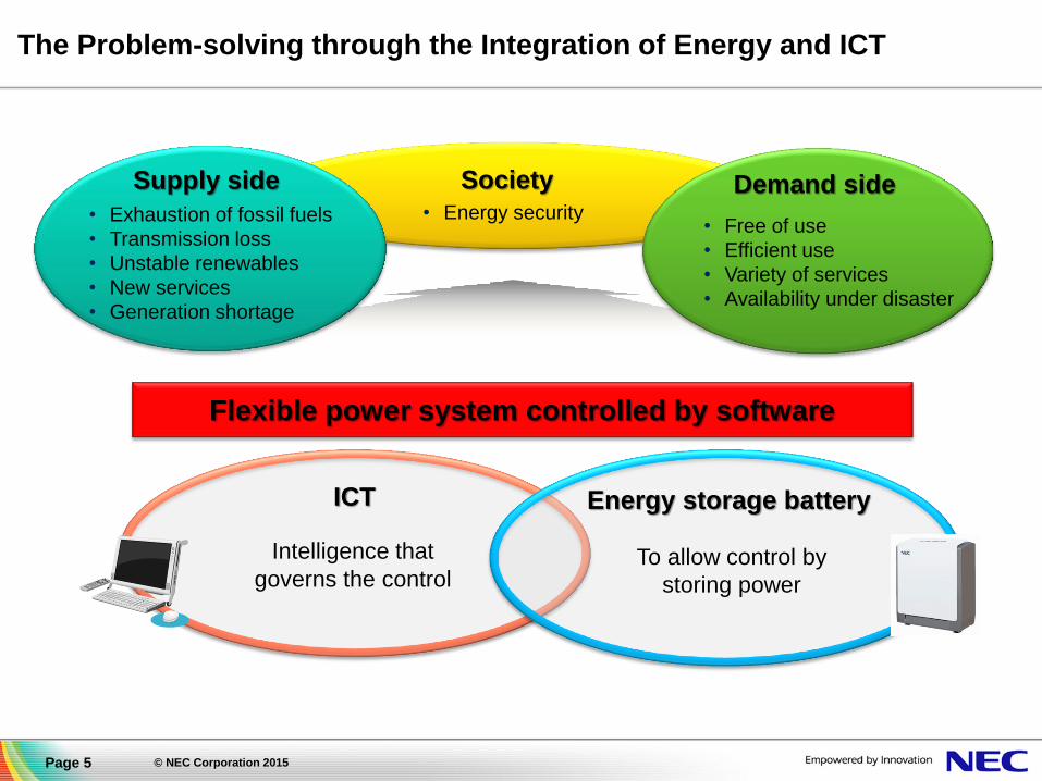
The Problem-solving through the Integration of Energy and ICT
• Exhaustion of fossil fuels
• Transmission loss
• Unstable renewables
• New services
• Generation shortage
• Free of use
• Efficient use
• Variety of services
• Availability under disaster
Supply side Demand side
Energy storage battery
To allow control by
storing power
ICT
Intelligence that
governs the control
Flexible power system controlled by software
Society
• Energy security

Page 6 © NEC Corporation 2015
BCP(Business Continuity Plan)
Solutions
Customers
Products
▌Contribute to the renewable energy development, power backup and energy supply-
demand balance
World top class technology and sales records
Various solutions can be offered by the substantial line-up.
System for the systems Lead-acid battery substitution
1-100MW class 10kW - - 10kW
Introduction of
Renewable energy
Frequency regulation
Backup
Power company,
developer,
power producer
Data center,
office building,
factory
Telecom
carrier
New market
(Emporium&
shelter)
System for data centers System for base station System for homes
5.53kWh
Backup
Peak cut &
Peak shift
Home,
store
10kW -
Already
commercialized
During demonstration
implementation Already
commercialized
Already
commercialized
Blackout measure
Peak cut & Peak shift
Backup
(BCP)
Blackout measure
Peak cut &
Peak shift
Already
commercialized
Energy Storage System Business

Page 7 © NEC Corporation 2015
NEDO Demonstration Project in India
◘ The project is under the energy dialogue joint statement between India (Planning Commission) & Japan (METI) governments.
◘ NEDO is sponsoring for EMS demonstration Project for Telecom Tower in India
◘ “NEC and PIXELA” are the trustee of NEDO. Two companies provide necessary technology for the Project.
◘ Demonstration Project; Execute the verification of EMS for diesel fuel
reduction of Telecom Tower with partner Tower companies, VIOM and GIL.
Japan India
MOF
NEC
(Owner)
PIXELA
NEDO MNRE, DOT
Telecom
Tower
Company
VIOM
GIL

Page 8 © NEC Corporation 2015
Objectives of this Demonstration project
◘ Evaluate energy efficiency improvement, i.e. fuel and
CO2 reduction, with our EMS/LiB and Photocatalyst coat.
◘ Evaluate the costs of installation, operation and
maintenance, to examine OPEX type business model.
◘ Evaluate LiB performance
under the Indian environmental
condition.
Tower
Diesel Generator Shelter
(Equipment inside)

Page 9 © NEC Corporation 2015
Overview of systems for this Project
Grid
Photovoltaic (PV)
EM
S c
on
tro
ller
BTS
Air
Conditioner
Diesel
Generator
Rectifier
EMS
remote
server
Operation
&
Monitoring
Center
Free Cooling
Unit (FCU)
Lithium Ion
Battery (LiB)
Photo-Catalyst
Coat on Shelter
Shelter
Key features for energy efficiency
◘ Combination of Li-Ion battery
and Server-Client model Energy
Management System (EMS).
◘ EMS manages the lowest cost
power source selection and
energy efficient charge to LiB.
◘ EMS remote server realizes
centralized monitoring and
analysis of operation data and
send energy control parameter
to EMS controllers.
◘ Photo-Catalyst Coat reflects
sunshine efficiently and mitigates
temperature rise in the shelter.
DC/AC

Page 10 © NEC Corporation 2015
LiB module and Photocatalyst Coat
▌ Photocatalyst Coating sample
▐ LiB module sample (3.3kWh)
6 units per site for this demonstration

Page 11 © NEC Corporation 2015
Power Generation Efficiency of Diesel Generator
▌ Power generation efficiency of DG is better with higher load.
▌ High rate charging characteristics of Lithium-Ion battery is suitable
for high load power generation of DG.
Load (%) Pow
er
Ge
nera
tion E
ffic
iency (
kW
h / L
itte
r)
Load with LiB (6.6kW)
Load with VRLA (4.3kW)
30% improvement of efficiency.
VRLA : Valve-Regulated Lead-Acid battery

Page 12 © NEC Corporation 2015
Expected Benefits- Fuel Consumption Reduction
▌ Simulation result of fuel consumption of Lead Acid and EMS/LiB.
▌ PV is not included in this simulation.
▌ At off-grid area, almost 40% of fuel consumption is reduced.

Page 13 © NEC Corporation 2015
Demonstration sites selection criteria for EMS/LiB
Expected OPEX reduction (w/o PV)
Grid Availability (Hours/Day)
▐Sites will be selected based on
their grid availability.
▐As shown in right side figure, fuel
reduction with our EMS is bigger
in poor grid area.
▐Five categories of grid availability.
Off grid: no grid availability.
Poor grid (1): grid is active about
3 hours per day in average.
Poor grid (2): grid is active about
6 hours per day in average.
Poor grid (3): grid is active about
9 hours per day in average.
Average grid: grid is active about
16 hours per day in average.
▐Select 4 sites for each category.
▐10 indoor and 10 outdoor sites.
Cost R
eduction (
Rupee/D
ay)

Page 14 © NEC Corporation 2015
The role of Photocatalyst Coat
KEY POINT;
• Reduction of the temperature rise of shelter by reflecting more than 85%
of sunlight.
• High reflectance can be maintained for more than 10 years by the
surface cleaning function.
• Pixela photocatalyst coat resists crack by wide temperature change.
Sun
85% of sunlight
Sunlight energy penetrates into house is less than 15%
Reflection
Photocatalyst Coat
Photocatalyst Coat
maintain high reflectance.

Page 15 © NEC Corporation 2015
Demonstration Site Distribution
• The effect of EMS and Photo-
catalyst coat are planed to be
verified at 60 sites.
• Area and site will be selected
based on climate and
grid availability.
Group EMS Photo-
catalyst
Site
configuration
Group A
(10 sites) ✔ ✔ Indoor.
Group A and
B is close to
each other. Group B
(10 sites) N/A ✔
Group C
(10 sites) ✔ N/A
Outdoor.
(enclosure)
Group D
(30 sites) N/A ✔
Indoor.
(shelter)

Page 16 © NEC Corporation 2015
Schedule of Demonstration Project
◘ Phase 1 Demonstration: EMS and Photo-catalyst evaluation on sites.
◘ Phase 2 Demonstration: Optimization of EMS parameters and algorithm.
FY2014 FY2015 FY2016
Preparation
Model Project
Phase 1
Analysis and
Optimization
Model Project
Phase 2
Analysis &
Report
Optimization
Analysis of Phase 2
Analysis of Phase 1
EMS parameters and algorithm
1H 2H 1H 2H 1H 2H
Reporting
Demo. Phase 2
Preparation of
Equipment
Installation MOU
System design
Demo. Phase 1
MoU Ceremony

Page 17 © NEC Corporation 2015
EMS Installation on the move
Outdoor type EMS with Lithium Ion Batteries
(Inside)
PV array installation

Page 18 © NEC Corporation 2015
Photocatalytic Coat Installation for Telecom Tower

Page 19 © NEC Corporation 2015
Conclusion
Through this demonstration project,
we will evaluate reduction of diesel fuel
consumption and CO2 emission
with our Energy Management System, LiB
and Photocatalyst coat.
Thank you.