ENERGY MANAGEMENT OF BATTERY TO DC MOTOR …umpir.ump.edu.my/id/eprint/175/1/shahir.pdf · vehicle...
24
ENERGY MANAGEMENT OF BATTERY TO DC MOTOR AHMAD SYAHIR BIN ZAINAL A report submitted in partial fulfillment of the requirements for the award of the degree Bachelor of Mechanical Engineering Faculty of Mechanical Engineering UNIVERSITI MALAYSIA PAHANG NOVEMBER 2008
Transcript of ENERGY MANAGEMENT OF BATTERY TO DC MOTOR …umpir.ump.edu.my/id/eprint/175/1/shahir.pdf · vehicle...

ENERGY MANAGEMENT OF BATTERY TO DC MOTOR
AHMAD SYAHIR BIN ZAINAL
A report submitted in partial fulfillment of the requirements for the award of the degree Bachelor of Mechanical Engineering
Faculty of Mechanical EngineeringUNIVERSITI MALAYSIA PAHANG
NOVEMBER 2008
ii
SUPERVISOR’S DECLARATION
We hereby declare that we have checked this project and in our opinion this project is
satisfactory in terms of scope and quality for the award of the degree of Bachelor of
Mechanical Engineering
Signature : _______________________________________
Name of Supervisor : _Associate Professor Dr Rosli Bin Abu Bakar__
Position : _Dean__________________________________
Date : _______________________________________
Signature : _______________________________________
Name of Panel : _Mr Devarajan A/L Ramasamy______________
Position : _Lecturer_______________________________
Date : _______________________________________

iii
STUDENT’S DECLARATION
I hereby declare that the work in this thesis is my own except for quotations and
summaries which have been duly acknowledged. The thesis has not been accepted for
any degree and is not concurrently submitted for award of other degree.
Signature : _______________________________________
Name : _Ahmad Syahir Bin Zainal_________________
ID Number : _MA05079______________________________
Date : _______________________________________

v
ACKNOWLEDGEMENTS
I would like to take this opportunity to express my deepest gratitude to Allah
because of His willingness to give me strength to finish this project successfully. First
and foremost, many warm thanks to my supervisor Associate Professor Dr Rosli bin
Abu Bakar and my co-supervisor Mr Vannebula Eka Indraguna for their constant help,
support and guidance which has steered me to finish my project. Their enthusiasm and
professional work has motivated me whenever I feel depress while doing my project.
Whenever I really need help, they always provide me with ideas which helped me
overcome the difficulties in doing my project. I am very grateful for their sincere help. I
would also like to thank Dr Yusnita Rahayu for her support and guidance with valuable
suggestion in doing my thesis and her strong passion always gave me a new hope. My
sincere thanks to Associate Professor Dr Wan Azhar bin Wan Yusoff for providing me
help and advice with SIMULINK model for this project. I thank Mr Devarajan A/L
Ramasamy who helped me in providing data from mechanical laboratory. Special
thanks to all my friends for taking the time to hear my problems during completing this
project. I am also thankful to all the staff of Mechanical Engineering Department,
University Malaysia Pahang (UMP), who helped me in many ways. My very special
thanks go to my housemates for their supports and encouragement.
My heartfelt thanks go to my beloved parents and my family who always
supported me and willing fully sacrifice themselves just to see me succeed. Last but not
the least, all the glory belonging to Allah. He is worthy of all praise.

vi
ABSTRACT
An electric vehicle (EV) is vehicles that use an electric as its power source.
Electricity can be generate by many ways like solar, wind and water. An EV will
produce almost zero emission. An EV used a direct current (DC) motor as exchange
with the internal combustion engine (ICE) in conventional vehicle and in hybrid electric
vehicle (HEV). A battery electric vehicle (BEV) is just using battery as its power source
which is different from HEV that are using ICE as a generator and as a secondary power
source that still produce pollution in the air. The energy for BEV is generated by battery
to DC motor. This part is known as energy management of battery to DC motor. There
is method to estimate the state of charge (SOC) from a battery. In this project, an
experiment have be done using 5 horsepower (HP) DC motor and a lead-acid battery to
estimate the SOC by using an open circuit voltage (OCV) of a battery. For charging
profile, a data is produced by using a 12V 20A charger that is connected to a series of
battery. A simulation for determining SOC of a battery to DC motor also have be done
by using a MATLAB software version 7.6.0 (R2008a). By an experiment, result of
charging and discharging profile are plotted into a graph and by a simulation using
MATLAB software, graph of discharging profile is plotted and by analyzed the result,
prediction of journey have been made and battery lifetime also can be determined. With
this both result, a comparison have been made to both result and an algorithm is been
produced consisting of an energy management of a battery to DC motor. With this
algorithm, an estimation of the energy left in the batteries that have been supply to
different load of DC motor should be easier. The new design of a battery charger also
been introduced in this thesis. By using a L200 component, the charger system should be
an intelligent circuit with additional features.
vii
ABSTRAK
Kenderaan elektrik (EV) ialah suatu kenderaan yang menggunakan tenaga
elektrik sebagai sumber tenaga utama. Tenaga elektrik boleh dihasilkan daripada
pelbagai cara seperti tenaga suria, angina dan air. EV hampir tidak mengeluarkan
sebarang pencemaran terhadap alam. EV menggunakan motor DC sebagai ganti kepada
internal combustion engine (ICE) yang digunakan dalam kenderaan konvensional dan
kenderaan elektrik hibrid (HEV). Kenderaan elektrik berbateri (BEV) hanya
menggunakan bateri sebagai sumber tenaga utama dimana berbeza dengan HEV yang
menggunakan ICE sebagai generator dan sebagai sumber tenaga kedua yang masih
menghasilkan pencemaran di dalam udara. Tenaga di dalam BEV dihasilkan dari bateri
ke motor DC. Bahagian ini dikenali sebagai pengurusan tenaga dari bateri ke motor DC.
Ada satu cara untuk mengukur state of charge (SOC) daripada bateri. Dalam projek ini,
satu eksperimen telah dilakukan dengan menggunakan 5 horsepower (HP) motor DC
dan lead-acid bateri untuk mengukur SOC melalui open circuit voltage (OCV) daripada
bateri. Untuk profil mengecas, data diperolehi dengan menggunakan pengecas 12V 20A
yang disambungkan kepada satu siri bateri. Simulasi untuk mengukur SOC daripada
bateri ke motor DC telah dilakukan menggunakan perisian MATLAB versi 7.6.0
(R2008a). Melalui satu eksperiment, satu keputusan profil pengecasan dan
pengediscasan telah dihasilkan dalam satu bentuk graf dan melalui simulasi dengan
menggunakan perisian MATLAB, hanya graf pengediscasan dapat dihasilkan dan
dengan menganalisa keputusan tersebut, ramalan tentang jarak perjalanan dapat dibuat
dan jangka hayat bateri turut dapat ditentukan. Dengan kedua-dua keputusan ini, satu
perbandingan telah dilakukan melauli kedua-dua keputusan ini dan satu algorithm telah
dapat dihasilkan tentang pengurusan tenaga daripada bateri ke motor DC. Dengan
terhasilnya algorithm ini, pengukuran tenaga yang masih berbaki di dalam bateri yang
telah diberi ke bebanan yang berlainan di dalam motor DC sepatutnya menjadi lebih
mudah. Rekaan baru sirkit pengecas bateri juga telah diperkenalkan di dalam tesis ini.

viii
Dengan menggunakan komponen L200, system pengecas sepatutnya menjadi sirkit yang
pintar dengan penambahan ciri-ciri lain.
ix
TABLE OF CONTENTS
Page
SUPERVISOR’S DECLARATION ii
STUDENT’S DECLARATION iii
DEDICATION iv
ACKNOWLEDGEMENTS v
ABSTRACT vi
ABSTRAK vii
TABLE OF CONTENTS ix
LIST OF TABLES xi
LIST OF FIGURES xii
LIST OF SYMBOLS xiv
LIST OF ABBREVIATIONS xv
CHAPTER 1: INTRODUCTION ……………………………………………………1
1.1 Introduction…………………………………………………… 1
1.2 Project Background…...………………………………………. 5
1.3 Project Objective……………………………………………… 5
1.4 Project Scope………………………………………………….. 5
1.5 Thesis Outline…………………………………………………. 6
CHAPTER 2: OVERVIEW OF ENERGY MANAGEMENT……………………..7
2.1 The Battery……………………………………………………. 7
2.1.1 Battery Management……………………………………. 7
2.1.2 Battery Modeling……………………………………...... 9
2.2 Battery or Cell Voltage……………………………………...... 11
x
2.2.1 Lead-Acid Battery…………………………………….. 11
2.2.2 NiMH Battery…………………………………………. 12
2.3 DC Motor…………………………………………………….. 12
CHAPTER 3: EXPERIMENT AND SIMULATION OF BATTERY TO DC
MOTOR USING MATHLAB……………………………………….14
3.1 Experiment Methods…………………………………………. 14
3.1.1 Charging Battery……………………………………….. 14
3.1.2 Discharging Battery…………………………………….. 15
3.2 Simulation Using Mathlab……………………………………. 15
3.2.1 Mathematical Calculation………………………………. 15
3.2.2 Step For Simulation…………………………………...... 16
CHAPTER 4: SOC ESTIMATION USING OCV…………………………………..22
4.1 Experimental Result…………………………………………... 22
4.1.1 Charging Profile………………………………………… 28
4.1.2 Prediction Journey by SOC…………………………….. 28
4.2 Simulation Using Mathlab Software………………………….. 33
4.3 Design Of Intelligent Charger Controller……………………... 35
CHAPTER 5: CONCLUSIONS AND FUTURE WORKS…………………………37
5.1 Conclusion……………………………………………………. 37
5.2 Future Works…………………………………………………. 38
LIST OF REFERENCES……………………………………………………………..39
APPENDICES A……………………………………………………………………....41
APPENDICES B………………………………………………………………………43
xi
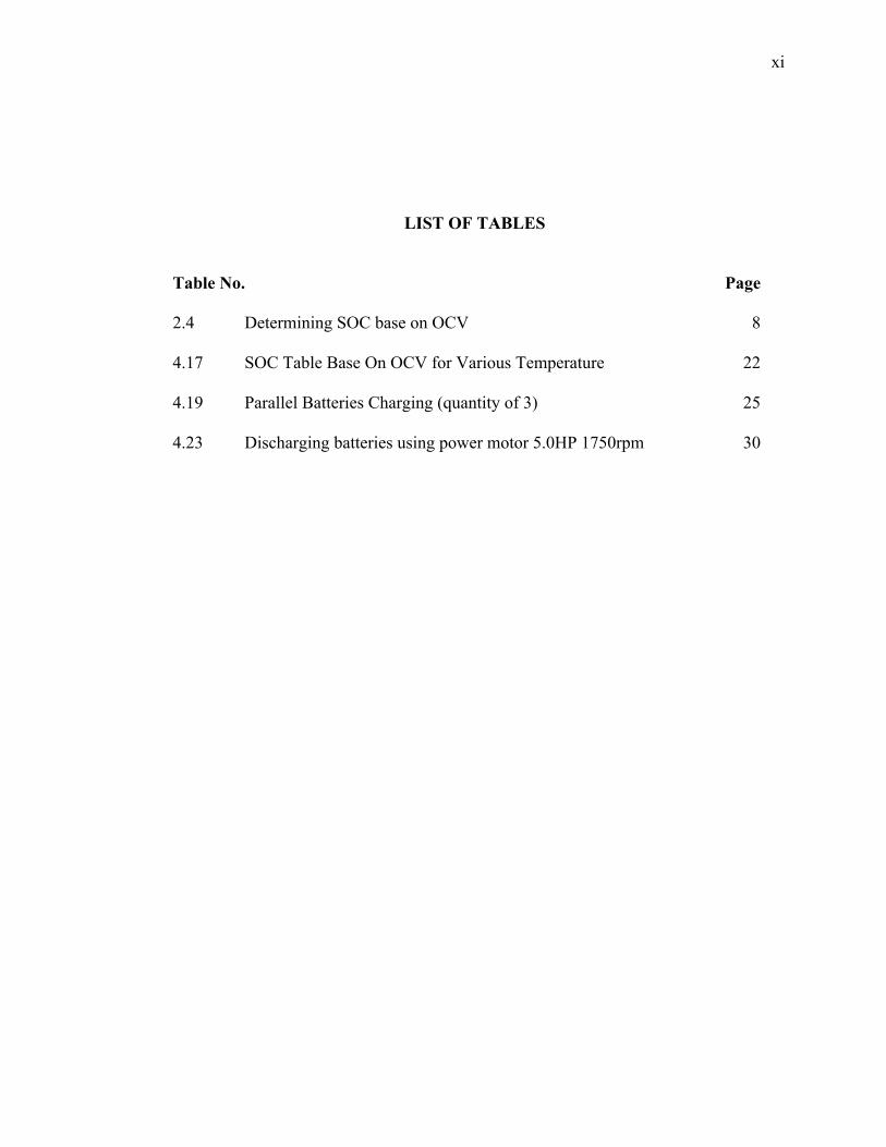
LIST OF TABLES
Table No. Page
2.4 Determining SOC base on OCV 8
4.17 SOC Table Base On OCV for Various Temperature 22
4.19 Parallel Batteries Charging (quantity of 3) 25
4.23 Discharging batteries using power motor 5.0HP 1750rpm 30
xii
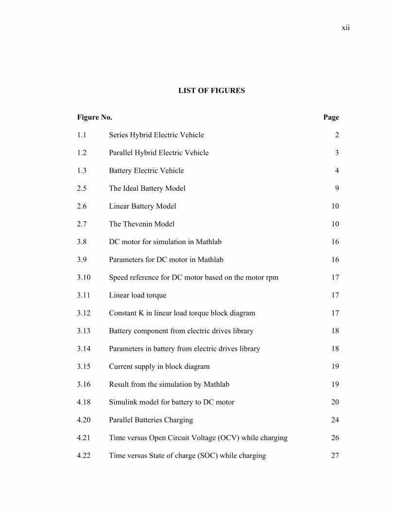
LIST OF FIGURES
Figure No. Page
1.1 Series Hybrid Electric Vehicle 2
1.2 Parallel Hybrid Electric Vehicle 3
1.3 Battery Electric Vehicle 4
2.5 The Ideal Battery Model 9
2.6 Linear Battery Model 10
2.7 The Thevenin Model 10
3.8 DC motor for simulation in Mathlab 16
3.9 Parameters for DC motor in Mathlab 16
3.10 Speed reference for DC motor based on the motor rpm 17
3.11 Linear load torque 17
3.12 Constant K in linear load torque block diagram 17
3.13 Battery component from electric drives library 18
3.14 Parameters in battery from electric drives library 18
3.15 Current supply in block diagram 19
3.16 Result from the simulation by Mathlab 19
4.18 Simulink model for battery to DC motor 20
4.20 Parallel Batteries Charging 24
4.21 Time versus Open Circuit Voltage (OCV) while charging 26
4.22 Time versus State of charge (SOC) while charging 27
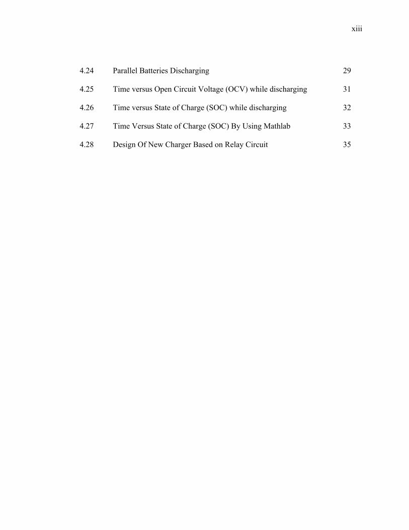
xiii
4.24 Parallel Batteries Discharging 29
4.25 Time versus Open Circuit Voltage (OCV) while discharging 31
4.26 Time versus State of Charge (SOC) while discharging 32
4.27 Time Versus State of Charge (SOC) By Using Mathlab 33
4.28 Design Of New Charger Based on Relay Circuit 35

xiv
LIST OF SYMBOLS
Pm Mechanical output power
ωm Omega, nominal speed in rad/s
Nm Nominal speed in rpm
π Pi, valued at 3.142
K Constant
Tm Mechanical load torque
xv
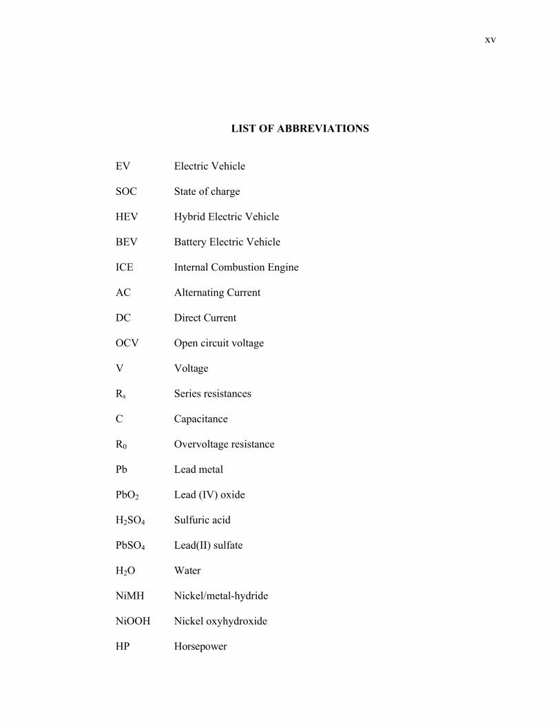
LIST OF ABBREVIATIONS
EV Electric Vehicle
SOC State of charge
HEV Hybrid Electric Vehicle
BEV Battery Electric Vehicle
ICE Internal Combustion Engine
AC Alternating Current
DC Direct Current
OCV Open circuit voltage
V Voltage
Rs Series resistances
C Capacitance
R0 Overvoltage resistance
Pb Lead metal
PbO2 Lead (IV) oxide
H2SO4 Sulfuric acid
PbSO4 Lead(II) sulfate
H2O Water
NiMH Nickel/metal-hydride
NiOOH Nickel oxyhydroxide
HP Horsepower
xvi
W Watt
A Ampere
Rpm Rotation per minute
Rad/s Radian per second
Ah Ampere-hour
Min/s Minute/s
SG Specific gravity
1
CHAPTER 1
INTRODUCTION
1.1 INTRODUCTION
An electric vehicle (EV) is the vehicle that use different source of energy from
the conventional vehicle. Power source of an EV gained from the electricity to supply
the energy to vehicle sub-system. An EV is produce to achieve zero emission vehicles.
A conventional vehicle produce a lot of environment pollution and this number are
raising rapidly as millions of people gain access to public and personal transportation.
Due to the oil price that now is unreasonable raise cause by lack of the petroleum from
all over the world, the automobile manufacturers find a ways to using others energy as
change to the petrol [1]. One of the energy that have being found is using the electricity
since 1931 in Paris [2]. Nowadays, the automobile manufacturers working harder to
improve the current EV to become more reliable and have a friendly use functions.
Many of the automobile manufacturers have produced an EV such as Daimler-Chrysler,
Ford, and General Motors that initially use Plumbum-acid batteries. Toyota and Honda
will use nickel metal-hydride batteries and Nissan will demonstrate vehicle using Li-ion
batteries as the energy [1]. As in the conventional vehicle, fuel gauge is use to
determine fuel left in the vehicle. In EV, the estimation of battery state of charge (SOC)
is important to determine the energy left in EV to predict journey that can reach by an
EV before empty and need to be charge [3]. Energy from the electricity is supplied by a
series of battery pack place in an EV. An EV divided by two categories that are Hybrid
Electric Vehicle (HEV) and Battery Electric Vehicle (BEV) [4].
2
HEV is an electric vehicle using both the petrol or diesel and battery as a power
source so hybrid mode can be change anytime necessary. In HEV there are also two kind
of HEV. Series HEV and parallel HEV.
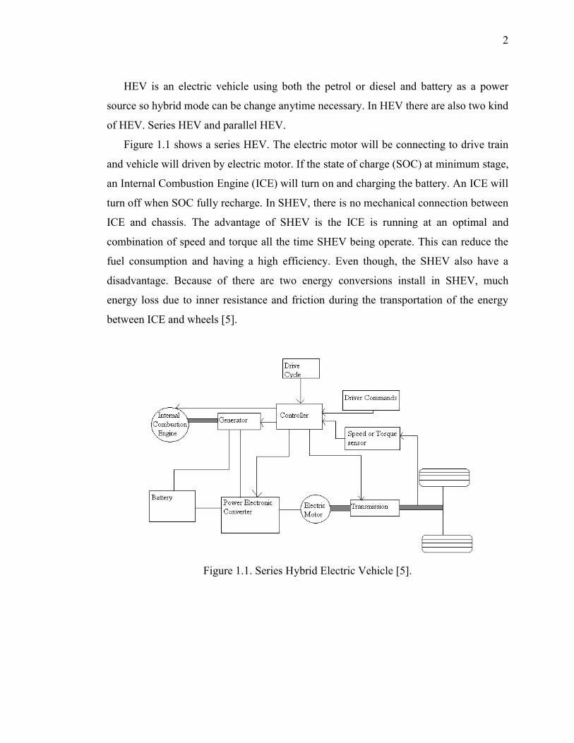
Figure 1.1 shows a series HEV. The electric motor will be connecting to drive train
and vehicle will driven by electric motor. If the state of charge (SOC) at minimum stage,
an Internal Combustion Engine (ICE) will turn on and charging the battery. An ICE will
turn off when SOC fully recharge. In SHEV, there is no mechanical connection between
ICE and chassis. The advantage of SHEV is the ICE is running at an optimal and
combination of speed and torque all the time SHEV being operate. This can reduce the
fuel consumption and having a high efficiency. Even though, the SHEV also have a
disadvantage. Because of there are two energy conversions install in SHEV, much
energy loss due to inner resistance and friction during the transportation of the energy
between ICE and wheels [5].
Figure 1.1. Series Hybrid Electric Vehicle [5].

3
Figure 1.2 shows a parallel HEV (PHEV). PHEV can be driven with both of ICE
and electric motor (EM) at the same time. This can make a PHEV to choose the
combination freely so the PHEV will be applied by the required torque at each time. To
combine these two ICE and EM is to use the EM alone at lower speed and leave ICE to
work at high speed so the EM will be more efficient than the ICE. When ICE is in
operate mode, an EM will act as a generator and charge the battery. When the power
demand is low, only the ICE will be use. When PHEV being accelerated and use high
speeds, the EM will be operate as a complement to ICE that will give extra power if
needed. An ordinary ICE is inefficient when operate at low speed so better to use EM at
low speeds [4].
Figure 1.2. Parallel Hybrid Electric Vehicle [4].
4
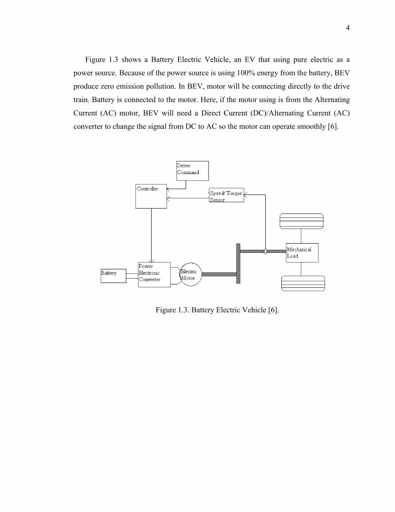
Figure 1.3 shows a Battery Electric Vehicle, an EV that using pure electric as a
power source. Because of the power source is using 100% energy from the battery, BEV
produce zero emission pollution. In BEV, motor will be connecting directly to the drive
train. Battery is connected to the motor. Here, if the motor using is from the Alternating
Current (AC) motor, BEV will need a Direct Current (DC)/Alternating Current (AC)
converter to change the signal from DC to AC so the motor can operate smoothly [6].
Figure 1.3. Battery Electric Vehicle [6].
5
1.2 PROJECT BACKGROUND
An EV has not been denied as one of the alternative effort to reduce the
environment pollution and cost that cause by a conventional vehicle. For an EV,
estimation of SOC is the important subject to be discussed. Methods for estimate SOC
have been done by [7] but this estimation is for Hybrid Electric Vehicle. An estimation
of SOC for lead-acid batteries also has been done by Ahmad Fasih [8]. Estimation of the
SOC for HEV is not a crime but the HEV still producing pollution and using a diesel as
its power source. World has tell that the petroleum producing is reducing each year and
even each month so, if the method of estimation SOC is for HEV then when the time has
come this method is not yet being approve if this method can be use by EV. This thesis
will define the energy management of BEV. This thesis want to define if the method of
estimation SOC for the HEV can also being applied to the BEV with various type of
load use.
1.3 PROJECT OBJECTIVE
The objective of this project is to develop an algorithm for the energy management
of Battery to DC motor based on the energy needed by the DC motor.
1.4 PROJECT SCOPE
Objective of this thesis is to develop an algorithm for energy management of BEV.
Thus, this thesis will consist:
1) Monitoring the state of charge (SOC) of battery for predictive battery lifetime
for different DC motor used.
2) Improving charger system to be more effective.
3) Design intelligent charger controller.

6
1.5 THESIS OUTLINE
Chapter 1 is about the introduction to the Electric Vehicle that used a DC motor
as a replace of an engine in conventional vehicle and the purpose of this thesis written to
give an explanation about this project.
Chapter 2 represented the battery modeling, the equation that will use to
complete this project and an overview on battery management of electric vehicle. This
chapter also will show on how the estimation of Voc and SOC will be determined.
Chapter 3 described the methods that are used to determine the Voc of the
battery and from this data, estimation of SOC can be done. This chapter also show the
experimental and simulation method.
Chapter 4 shows the result get from both of experiment and simulation method,
compared and will be discuss to get the algorithm of energy management of battery to
DC motor.
Chapter 5 presents the summary and conclusions to complete this project.
7
CHAPTER 2
OVERVIEW OF ENERGY MANAGEMENT OF ELECTRIC VEHICLE
From the research, estimation of the SOC is done by using the extended Kalman
filter (EKF) for the HEV [7]. So, this project wants to estimate the SOC by different
energy of battery and different kind of DC motor by using the experiment and
simulation using MATLAB software.
2.1 THE BATTERY
Battery is important in the BEV because it supply the energy to move the vehicle
and make it works. Thus, battery management is very important for energy management
in BEV.
2.1.1 Battery Management
The automotive is a passive standalone and very important component in the
Electric Vehicle (EV). Precise monitoring and active control of the battery are needed in
the energy management and powertrain hybridization. The battery monitoring are known
as a continuously calculating application-relevant battery state quantities based on
sensed physical quantities, typically current, voltage, and temperature. “Configurations
of this type have been common for traction batteries for some time, but have more
recently been introduced for demanding 12V SLI battery applications as well. Examples
for active control measures are state-of-charge (SOC) control by discharge/charge
management and thermal management that maintains upper and lower temperature
thresholds and limits temperature gradients within the battery.
8
Together with subsystems involving elements such as sensors, monitoring
algorithms, and cooling fans, the battery then forms an energy storage system that
interacts with the vehicle in a complex manner”. This is meant that state of charge
(SOC) is important to determining rate capacity of batteries. The SOC also needed to
determining end of the charging and discharging the batteries. To determining the SOC,
there are various methods such as direct measurement, specific gravity (SG)
measurement, voltage based SOC estimation and also current based SOC estimation.
The SOC calculation is important for the batteries in the battery management so the
power that will be deliver to the load in the maximum state.
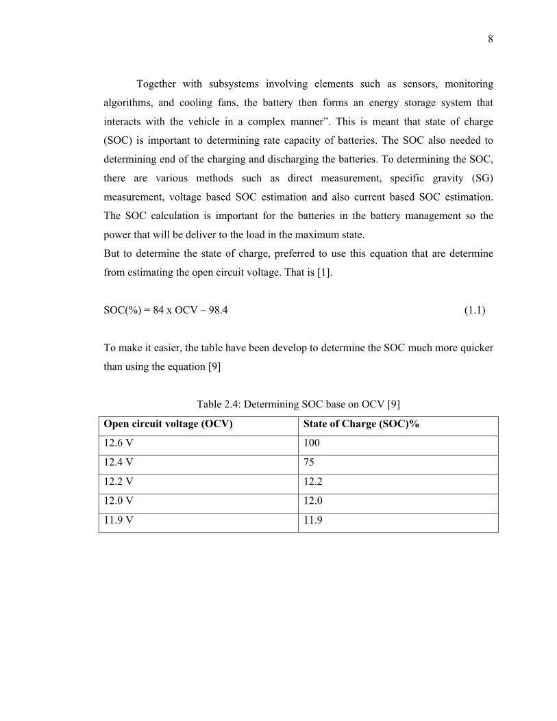
But to determine the state of charge, preferred to use this equation that are determine
from estimating the open circuit voltage. That is [1].
SOC(%) = 84 x OCV – 98.4 (1.1)
To make it easier, the table have been develop to determine the SOC much more quicker
than using the equation [9]
Table 2.4: Determining SOC base on OCV [9]
Open circuit voltage (OCV) State of Charge (SOC)%
12.6 V 100
12.4 V 75
12.2 V 12.2
12.0 V 12.0
11.9 V 11.9
9
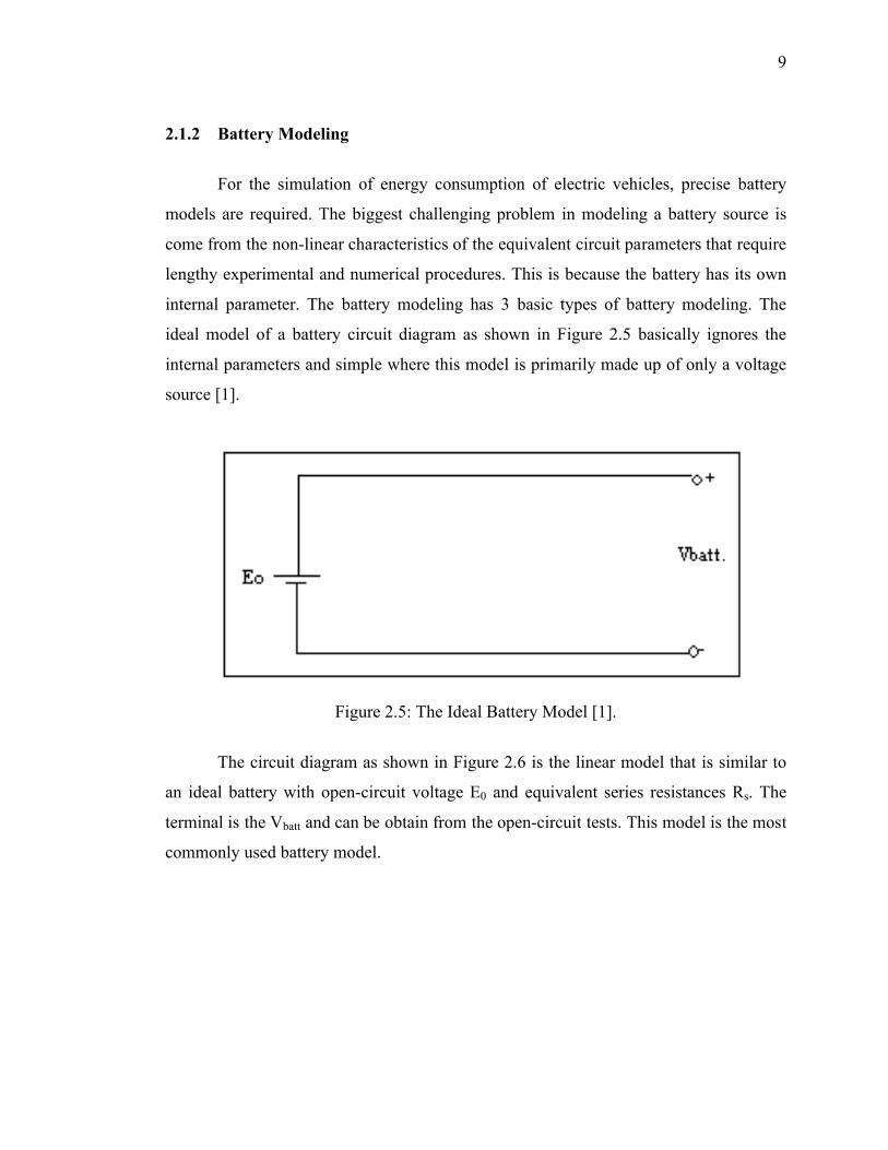
2.1.2 Battery Modeling
For the simulation of energy consumption of electric vehicles, precise battery
models are required. The biggest challenging problem in modeling a battery source is
come from the non-linear characteristics of the equivalent circuit parameters that require
lengthy experimental and numerical procedures. This is because the battery has its own
internal parameter. The battery modeling has 3 basic types of battery modeling. The
ideal model of a battery circuit diagram as shown in Figure 2.5 basically ignores the
internal parameters and simple where this model is primarily made up of only a voltage
source [1].
Figure 2.5: The Ideal Battery Model [1].
The circuit diagram as shown in Figure 2.6 is the linear model that is similar to
an ideal battery with open-circuit voltage E0 and equivalent series resistances Rs. The
terminal is the Vbatt and can be obtain from the open-circuit tests. This model is the most
commonly used battery model.