Amorphous Metal Ribbons and Metal Amorphous Nanocomposite ...
Upload
phungquynhCategory
view
233download
2
Energy Efficiency of Amorphous Metal Based Transformers
R. HasegawaMetglas, Inc
440 Allied Drive, SC 29526 USA
October 2004

OVERVIEW•Basics•Introduction
Amorphous versus crystalline magnetic materialProperties of amorphous magnet - why amorphous ?Exchange Interaction and MagnetizationMagnetic Anisotropy, Magnetostriction, Magnetic Domain and StructureB-H Characteristics and Magnetization ProcessesMagnetic Losses
•ApplicationsElectric Power TransformersHigh Frequency Power ElectronicsTelecommunicationPulse Transformers and Pulse Power DevicesMagnetic Sensors and Electronic Article SurveillanceAutomotive MagneticsMedical ApplicationsMagnetic Shielding
FUNDAMENTALS
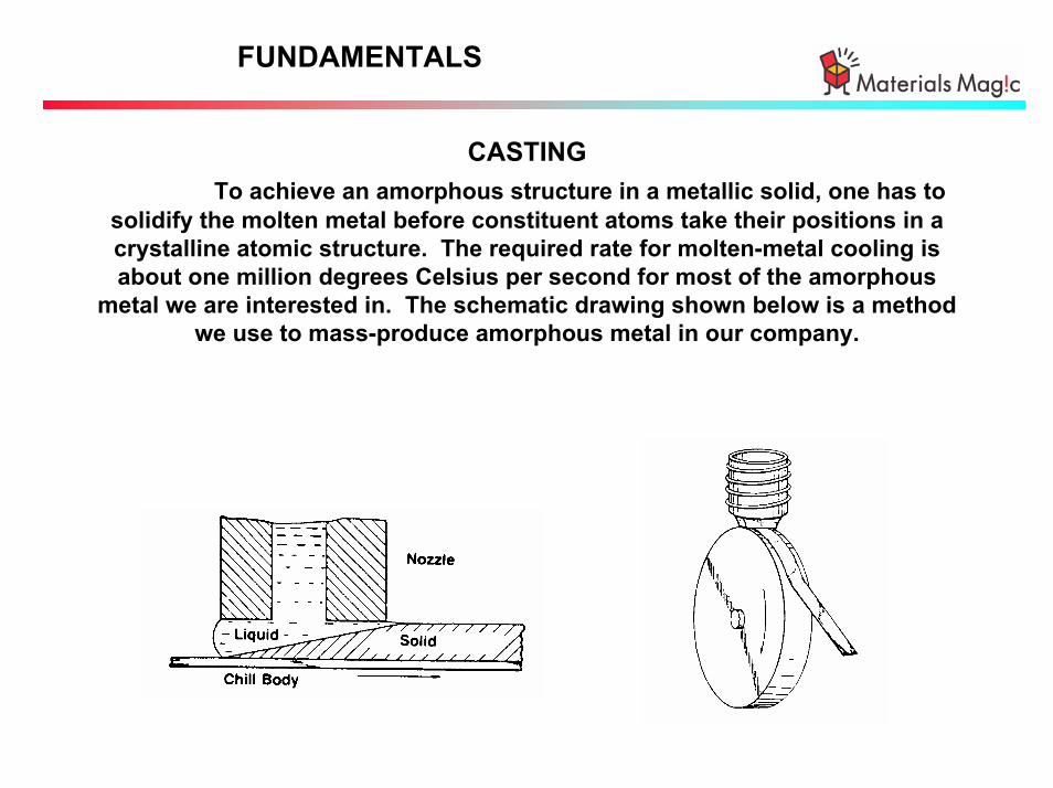
CASTINGTo achieve an amorphous structure in a metallic solid, one has to
solidify the molten metal before constituent atoms take their positions in a crystalline atomic structure. The required rate for molten-metal cooling is about one million degrees Celsius per second for most of the amorphous
metal we are interested in. The schematic drawing shown below is a method we use to mass-produce amorphous metal in our company.
FUNDAMENTALS
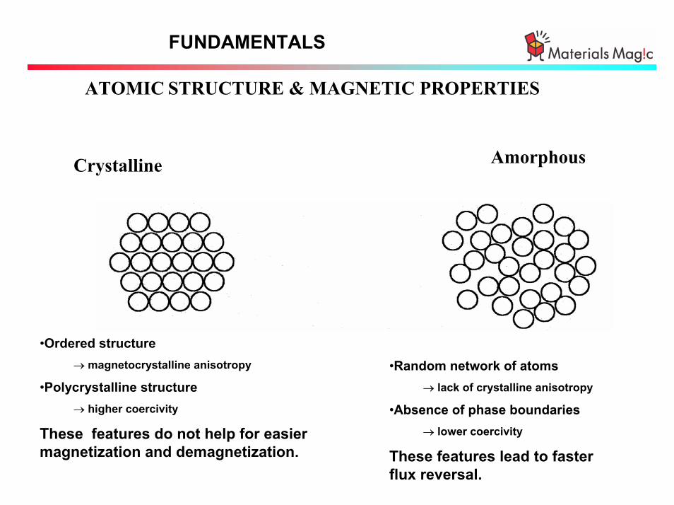
ATOMIC STRUCTURE & MAGNETIC PROPERTIES
AmorphousCrystalline
•Ordered structure→ magnetocrystalline anisotropy
•Polycrystalline structure→ higher coercivity
These features do not help for easier magnetization and demagnetization.
•Random network of atoms→ lack of crystalline anisotropy
•Absence of phase boundaries→ lower coercivity
These features lead to faster flux reversal.

ATOMIC STRUCTURE - AMORPHOUS

FUNDAMENTALS OF AMORPHOUS METAL
Electrical PropertiesThe electrical resistivity of many amorphous metals ranges from about 100 to 150 µΩ-cm. This is two-to-three times higher than
that of silicon steel or Fe50-Ni50 alloy, which is partially responsible for low core losses in these metals.
The temperature coefficient of the resistivity is relatively low and can reach nearly zero in some of the Fe-based alloys.
Mechanical PropertiesAmorphous metals are hard with Vickers hardness ranging from about 700 to 1000, but mechanically ductile in the as-cast state.
Elastic modulus is about 60x109 N/m2 .Thermal expansion coefficient is about 6-13 ppm/oC.

MAGNETIZATION PROCESS AND CORE LOSS
Magnetization processes are via uniform rotation ( high frequency limit) and domain wall motion (low frequency limit).Macroscopic magnetic loss (e.g. core loss) arises from eddy current (caused by magnetization rotation) and hysteresis behavior (caused by domain wall motion).
Empirically we find:
Core Loss = a B 1.5-2 f + b B 1.5-2.5 f 1.5-2
Core Loss /f = a B 1.5-2 + B 1.5-2 f 0.5-1.0
(loss separation)
0.1 1 10 100 10000.001
0.01
0.1
1
10
100
1000
Frequency (kHz)
Cor
e Lo
ss
(W/k
g)
Supermalloy25 µm
METGLAS 2714A25 µm
H7C4 (ferrite)(estimated)
Supermendur100 µm
Deltamax50 µm
METGLAS SA-125 µm
Bmax=0.2T

FUNDAMENTALS
SOFT MAGNETIC PROPERTIES
0.0
0.5
1.0
1.5
2.0
2.5
3.0
-3 -2 -1 0 1 210 10 10 10 10 10
Fe-50Co
Carbon SteelFe--
Soft Ferrites
PermalloyPowder
Fe-3SiFe-6.5Si
Fe-baseAM
Fe-(40-50)Ni
Fe & Fe
Alloy Powder
Fe-Ni base AM
Co-baseAM
Fe-(70-80)Ni
Coercivity (A/cm)
Saturation Induction (T)
⋅
2
3
4
5
6
7
-3 -2 -1 0 1 2
10
10
10
10
10
1010 10 10 10 10 10
• Supermalloy
• Sendust
• 78 Permalloy
Ni-Zn Ferrite• Fe-3Si
• Hipernik
Mg-ZnFerrite
• Fe
Co-base AM
Fe-Ni base AM
Fe-base AM
Coercivity (A/cm)
Relative Permeability

FUNDAMENTALS OF AMORPHOUS METAL
Why amorphous versus crystalline soft magnets ?
Examples: Effects of Field AnnealingB
H
LONGITUDINAL TRANSVERSE

FUNDAMENTALS OF MAGNETICS
• Why amorphous versus crystalline soft magnets ?
Amorphous Metals exhibit:- easier magnetization (low coercivity and high permeability);- lower magnetic loss (low coercivity, high permeability and high
resistivity);- faster flux reversal (as a result of low magnetic loss)- versatile magnetic properties resulting from post-fabrication
heat-treatments and a wide range of adjustable chemicalcompositions.

ELECTRICAL POWER APPLICATIONS
Three basic families of amorphous soft ferromagnets
Fe-Base (e.g. METGLAS2605SA1)Main Application: Distribution Transformer

ELECTRICAL POWER APPLICATIONS
• High saturation induction and low core losses at 50/60 Hz are
required for electrical transformer applications.
• Amorphous metal-based transformers have 75-80% lower core
losses than crystalline Fe-Si base units under linear loads. When
higher harmonics are present, the difference in core losses becomes
even greater.
• Load losses are still less than Fe-Si based transformers.
• Significant savings can be achieved when existing Fe-Si based
transformers are replaced by amorphous metal-based units.
• The energy efficiency translates to reduced emission of
hazardous gasses such as CO2, SO2, etc.

NO LOAD LOSSES
Amorphous vs SiFe Steel Transformers
Core Loss (W)Transformer
Rating Silicon SteelIn Service Best
Amorphous MetalLoss
Reduction%
50 kVA, 1-Phase
300 kVA, 3-Phase
210
1000
35
165
75 to80%
105
500

TRANSFORMER LOSS
Amorphous vs SiFe Steel Transformers
96.0%
96.5%
97.0%
97.5%
98.0%
98.5%
99.0%
99.5%
100.0%
0% 25% 50% 75% 100% 125% 150%
Load
% E
ffic
ien
cy
Amorphous Metal
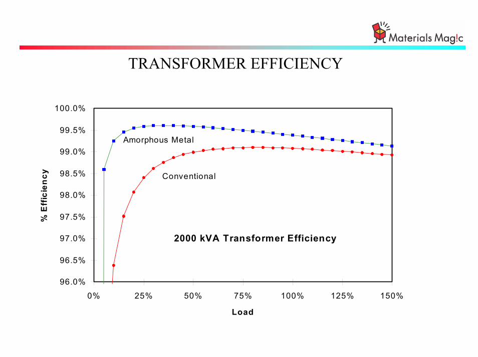
2000 kVA Transformer Efficiency
Conventional
TRANSFORMER EFFICIENCY

IMPACT ON Co2 GAS GENERATION
0
2 000
4 000
6 000
8 000
10 000
12 000
14 000
16 000
18 000
20 000
0% 25% 50% 75% 100%
Load
Wat
ts
UltraGlas Other Cast Coil
Other Cast CoilUltraGlas
2000 kVA ComparisonWatt Rating
Average LoadingRange - Commercialand Industrial


AMORPHOUS METAL TRANSFORMERS & TOTAL HARMONIC DISTORTION
“ Build-In” Superior Performance for Harmonic Conditions

What Are Harmonics And Where Are They Found ?
Adjustable Speed Motor Drives
UPSHID Lighting
PCs
“Pure” Power“Distorted” Power
-200
-150
-100
-50
0
50
100
150
200
0
0
Commercial &Industrial
Utility Generation
24 kV 765 - 236 kV
Transmission
230 - 34.5 kV
Subtransmission
Step Down
34.5 - 1.2 kV
Primary Distribution
Secondary Distribution
< 1.2 kV
Substation DistributionStep Up

Harmonics Basics
5th Harm(300 Hz) =79.5 Amp RMS
-150
-100
-50
0
50
100
150
0 0.004 0.008 0.012 0.016
fundamental =100 Amp RMS
-200
-150
-100
-50
0
50
100
150
200
0 0.004 0.008 0.012 0.016
7th Harm(420 Hz) =66 Amp RMS
-150
-100
-50
0
50
100
150
0 0.004 0.008 0.012 0.016
ASD Line Current =143.8 Amp RMS
-400
-300
-200
-100
0
100
200
300
400
0 0.004 0.008 0.012 0.016
Any periodic waveform can be considered as a summation of sinusoidal waveform of
different discrete frequencies

500 KVA Transformer Loss Study
0
2
4
6
8
10
12
14
16
18
20
22
24
0 0.2 0.4 0.6 0.8 1 1.2
Tota
l Los
ses
(kW
)
Actual hourly and weekday/weekend data
Expected losses based on laboratory NL and LL tests
AM AM
SiFe
SiFe
Total Loss Increase: ~100 % (Amorphous) ; ~300 % (SiFe)
Load Ratio

% o
f Fun
dam
enta
l2
67
40
7 7 4 20
20
40
60
80
100
3 5 7 9 11 13 15
Harmonic #
75 % THD
Laboratory Test Data on Harmonics Effects on No Load Losses(30 kVA Units with Identical Coils)
50 80
230
770
0
100
200
300
400
500
600
700
800
900
"Pure" Power w/ 75% THD
No
Load
Los
s (W
)
AMTSiFe
No-Load Loss Increase: 60% (Amorphous) ; 235% (Silicon Steel)

250 KVA Transformer Losses @ ~56% Loading ERDA Industrial Site Field Tests
966
1553
1084
1671
155
155
33
74
311
698
99
99
0
500
1000
1500
2000
2500
3000
Expected AMT Actual AMT Expected CRGO Actual CRGO
Loss
es (W
)
Core Eddy CurrentCore HysterisisCoil
AM Increase - 41 W SiFe Increase - 387 W
AMT Performance under Harmonics
Eddy Current Losses Increase in Both the Core and Coil, but Much Less for the Amorphous Core
Harmonic Impact on Transformer Losses
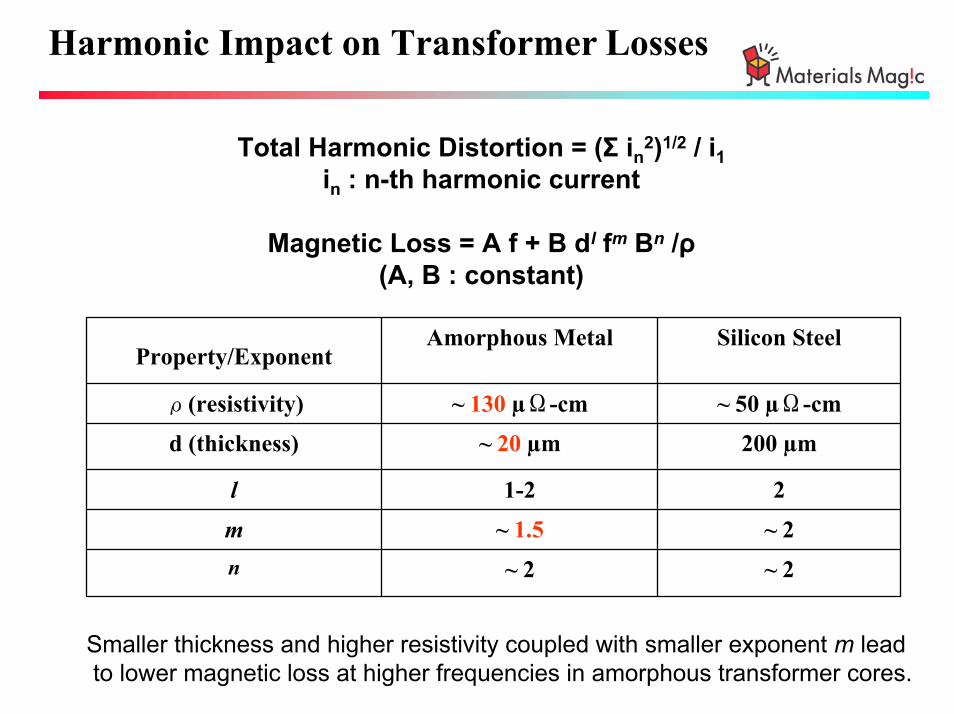
Total Harmonic Distortion = (Σ in2)1/2 / i1in : n-th harmonic current
Magnetic Loss = A f + B dl fm Bn /ρ(A, B : constant)
~ 2~ 2n
~ 2~ 1.5m
21-2l
200 µm~ 20 µmd (thickness)
~ 50 µΩ-cm~ 130 µΩ-cmρ(resistivity)
Silicon SteelAmorphous MetalProperty/Exponent
Smaller thickness and higher resistivity coupled with smaller exponent m leadto lower magnetic loss at higher frequencies in amorphous transformer cores.

Harmonic Impact on Transformer Losses -250 kVA
A. Harmonic Content (THD~25%)
5169110201100Content (%)
1715131197531Harmonics
B. Transformer Losses without Harmonic Distortion
1,5501,098Total Transformer Loss
5855Loading Level (%)
1,084966Coil Loss
466132Total Core Loss
31133Eddy Current
15599Hyteresis
Silicon SteelAmorphous MetalLoss (W)
C. Transformer Losses with Harmonic Distortion of Table A
2,5241,726Total Transformer Loss
5855Loading Level (%)
1,6711,553Coil Loss
853173Total Core Loss
69874Eddy Current
15599Hyteresis
Silicon SteelAmorphous MetalLoss (W)

Harmonic Impact on Transformer LossesTwofold Effect
• INCREASES NO-LOAD LOSS• DECREASES POWER FACTORVOLTAGE DISTORTION
• INCREASES WINDNG LOSS• INDUCES VOLTAGE DISTORTION,INCREASING NO-LOAD LOSS
CURRENT DISTORTION
Direct Consequences:
• Very High Total Transformer Losses – much higher than spec values
• Transformer Failure / Electrical Fire
Associated Problems:
• Deterioration of Electrical Power Quality
• Extra Energy Cost – Decreased Distribution Capacity
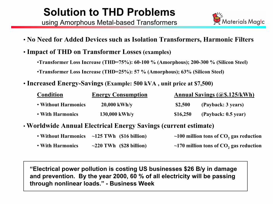
• No Need for Added Devices such as Isolation Transformers, Harmonic Filters
• Impact of THD on Transformer Losses (examples) •Transformer Loss Increase (THD=75%): 60-100 % (Amorphous); 200-300 % (Silicon Steel)
•Transformer Loss Increase (THD=25%): 57 % (Amorphous); 63% (Silicon Steel)
• Increased Energy-Savings (Example: 500 kVA , unit price at $7,500)
Condition Energy Consumption Annual Savings (@$.125/kWh)• Without Harmonics 20,000 kWh/y $2,500 (Payback: 3 years)
• With Harmonics 130,000 kWh/y $16,250 (Payback: 0.5 year)
• Worldwide Annual Electrical Energy Savings (current estimate)• Without Harmonics ~125 TWh ($16 billion) ~100 million tons of CO2 gas reduction
• With Harmonics ~220 TWh ($28 billion) ~170 million tons of CO2 gas reduction
Solution to THD Problemsusing Amorphous Metal-based Transformers
“Electrical power pollution is costing US businesses $26 B/y in damage and prevention. By the year 2000, 60 % of all electricity will be passing through nonlinear loads.” - Business Week

CONCLUSIONS
• Under pure ‘sinusoidal’ excitation, amorphous metal-based transformers exhibit about ¼ of the no-load loss of a high-grade silicon-steel. This corresponds to an annual worldwide potential savings of about 125 TWh and annual reduction of CO2 emission of about 100 million tons.
•Under harmonic conditions which are the actual conditions we are in, potential energy savings are considerably higher than the above. The energy savings is estimated at ~220 TWh.
•Worldwide use of amorphous metal-based transformers, therefore, will help us reduce fossil-fuel dependency and create cleaner environment with higher air quality.