Energetic Efficiency of Evaporation Plants · Project Management, ... Orange and other citrus ......
24
GEA Process Engineering Applications, Types, Components, Economic and Energetic Efficiency of Evaporation Plants Evaporation Technology engineering for a better world
Transcript of Energetic Efficiency of Evaporation Plants · Project Management, ... Orange and other citrus ......
GEA Process Engineering
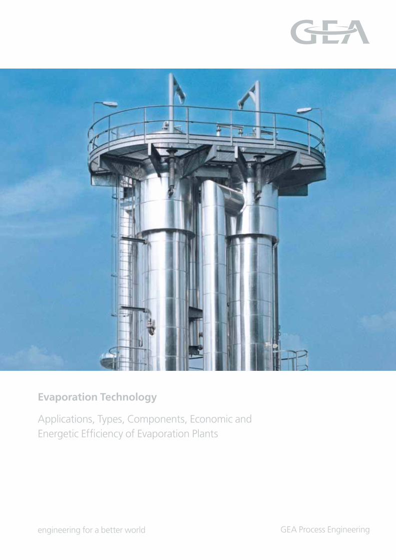
Applications, Types, Components, Economic and Energetic Efficiency of Evaporation Plants
Evaporation Technology
engineering for a better world
2
Research and Development
GEA Wiegand has its own Research and Development Centre,
where numerous laboratory and pilot plants are available for
detailed analyses and testing in the field of evaporation and
distillation. At the R&D Centre, important physical character
istics such as boiling point elevation, surface tension, solubi
lity and maximum achievable concentration are determined.
Certain pilot plants are available as mobile units and can there
fore be installed at a customer’s site. Data is captured and plant
operating behaviour modelled by means of the latest com puter
programs.
The tests are performed in different types of tubular and plate
evaporators and distillation columns. To date, more than 3,000
product categories have been tested through our plants. The
alphabetical list of products tested ranges from acetone/alcohol
mixtures to zinc dichloride.
Evaporation Technology
Contents
Research and Development 2
Reference Products from GEA Wiegand Evaporation Plants 3
Evaporator Types 4
Special Evaporator Types 11
Quantities and Concentration Ratios in Evaporation Plants 14
Energy Efficiency of Evaporation Plants 15
Criteria for the Design Selection, Arrangement and
Operating Modes of Evaporation Plants 19
Evaporation Plant Components 19
Measuring and Control Equipment 22
Project Management, Commissioning and After-Sales Service 23
Due to ongoing research and de-
velopment work spanning many
decades, and the experience of
several thousand installed refer-
en ces, GEA Wiegand continues to
provide the broadest technical ex-
pertise and the respected ability
to offer the best solution for almost
any product, evaporation rate,
operating condition or application.
Evaporation plants are used as a thermal separation technol
ogy, for the concentration or separation of liquid solutions,
suspensions and emulsions.
A liquid concentrate that can still be pumped is generally the
desired final product. Evaporation may however also aim
at separating the volatile constituents, or distillate, as would
be the case in a solvent separation system. During these pro
cesses, it is usual that product qualities are maintained and
pre served.
These, together with many other requirements result in a wide
variety of evaporator types, operating modes and arrangements.
GEA Wiegand has substantially contributed to the develop
ment of evaporation technology. The first Wiegand evaporator,
built in 1908, was a patented multipleeffect circulation eva
porator. This concentrated liquids in a gentle and efficient man
ner in a way unparalleled in its time. It was easy to control and
had a compact arrangement.
Further technical developments led to the first Wiegand falling
film evaporator, built in 1952, which combined these consider
ably improved, essential characteristics with new process
possibilities, especially in the field of evaporating heatsensitive
products. At the same time, the thermal efficiency of evapora
tion plants was considerably improved.
Thanks to its advantages, the falling film evaporator has virtu
ally replaced other evaporator types in many fields. Forced
circulation and circulation evaporators still have some signifi
cance, whereas special types such as spiral tube, counterflow or
stirrer evaporators are only used in special circumstances.
3
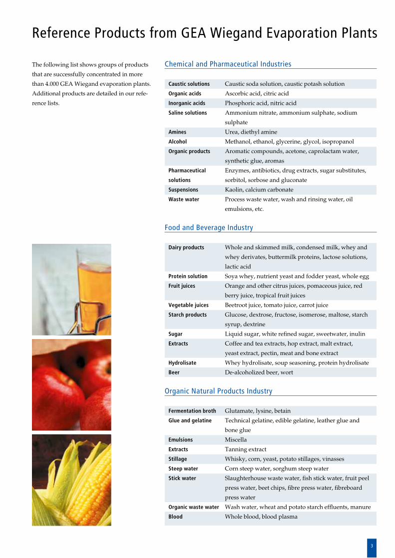
The following list shows groups of products
that are successfully concentrated in more
than 4.000 GEA Wiegand evaporation plants.
Additional products are detailed in our refe
rence lists.
Reference Products from GEA Wiegand Evaporation Plants
Chemical and Pharmaceutical Industries
Caustic solutions Caustic soda solution, caustic potash solution
Organic acids Ascorbic acid, citric acid
Inorganic acids Phosphoric acid, nitric acid
Saline solutions Ammonium nitrate, ammonium sulphate, sodium
sulphate
Amines Urea, diethyl amine
Alcohol Methanol, ethanol, glycerine, glycol, isopropanol
Organic products Aromatic compounds, acetone, caprolactam water,
synthetic glue, aromas
Pharmaceutical Enzymes, antibiotics, drug extracts, sugar substitutes,
solutions sorbitol, sorbose and gluconate
Suspensions Kaolin, calcium carbonate
Waste water Process waste water, wash and rinsing water, oil
emulsions, etc.
Food and Beverage Industry
Dairy products Whole and skimmed milk, condensed milk, whey and
whey derivates, buttermilk proteins, lactose solutions,
lactic acid
Protein solution Soya whey, nutrient yeast and fodder yeast, whole egg
Fruit juices Orange and other citrus juices, pomaceous juice, red
berry juice, tropical fruit juices
Vegetable juices Beetroot juice, tomato juice, carrot juice
Starch products Glucose, dextrose, fructose, isomerose, maltose, starch
syrup, dextrine
Sugar Liquid sugar, white refined sugar, sweetwater, inulin
Extracts Coffee and tea extracts, hop extract, malt extract,
yeast extract, pectin, meat and bone extract
Hydrolisate Whey hydrolisate, soup seasoning, protein hydrolisate
Beer Dealcoholized beer, wort
Organic Natural Products Industry
Fermentation broth Glutamate, lysine, betain
Glue and gelatine Technical gelatine, edible gelatine, leather glue and
bone glue
Emulsions Miscella
Extracts Tanning extract
Stillage Whisky, corn, yeast, potato stillages, vinasses
Steep water Corn steep water, sorghum steep water
Stick water Slaughterhouse waste water, fish stick water, fruit peel
press water, beet chips, fibre press water, fibreboard
press water
Organic waste water Wash water, wheat and potato starch effluents, manure
Blood Whole blood, blood plasma
4
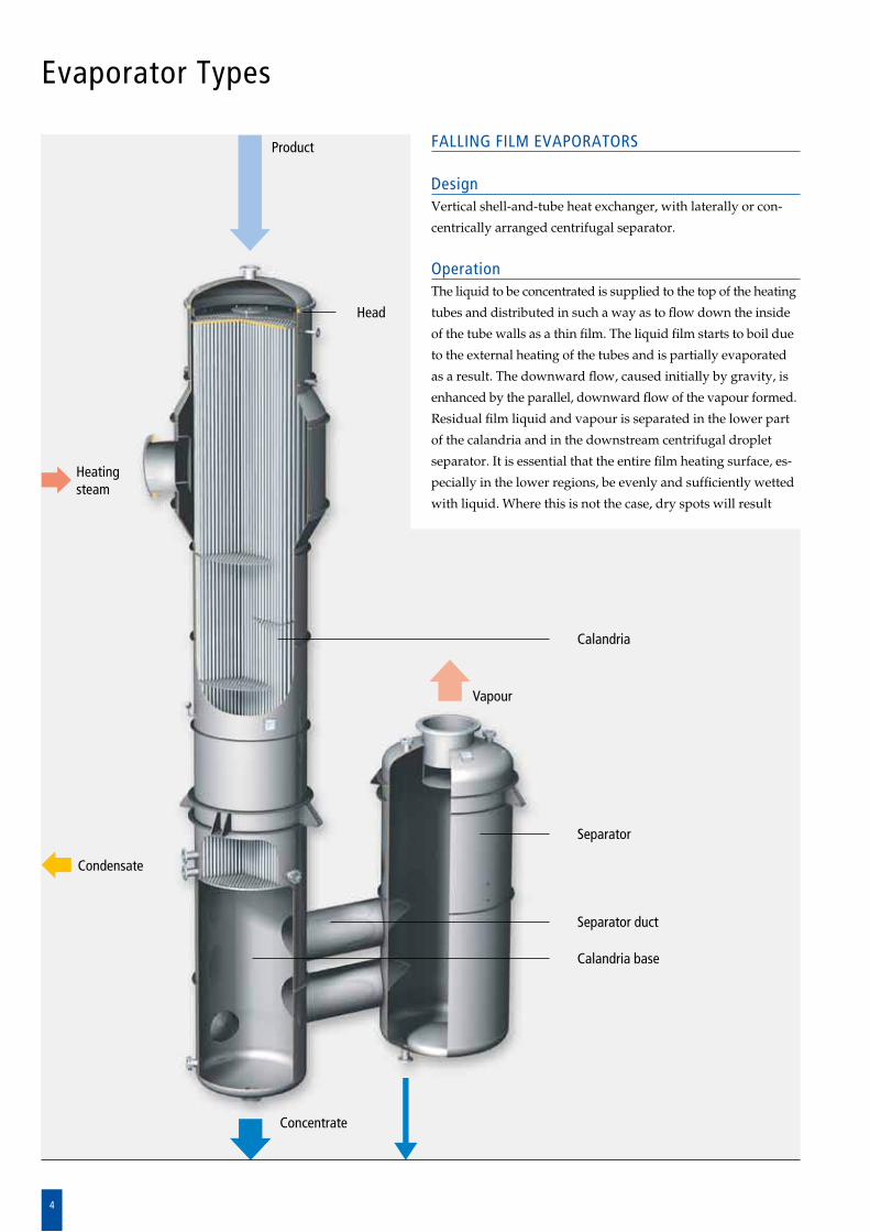
Evaporator Types
FALLING FILM EVAPORATORS
DesignVertical shellandtube heat exchanger, with laterally or con
cen trically arranged centrifugal separator.
OperationThe liquid to be concentrated is supplied to the top of the heating
tubes and distributed in such a way as to flow down the inside
of the tube walls as a thin film. The liquid film starts to boil due
to the external heating of the tubes and is partially evaporated
as a result. The downward flow, caused initially by gravity, is
enhanced by the parallel, downward flow of the vapour formed.
Residual film liquid and vapour is separated in the lower part
of the calandria and in the downstream centrifugal droplet
separator. It is essential that the entire film heating surface, es
pe cially in the lower regions, be evenly and sufficiently wetted
with liquid. Where this is not the case, dry spots will result
Vapour
Head
Calandria
Separator
Separator duct
Calandria base
Concentrate
Heating steam
Condensate
Product
5
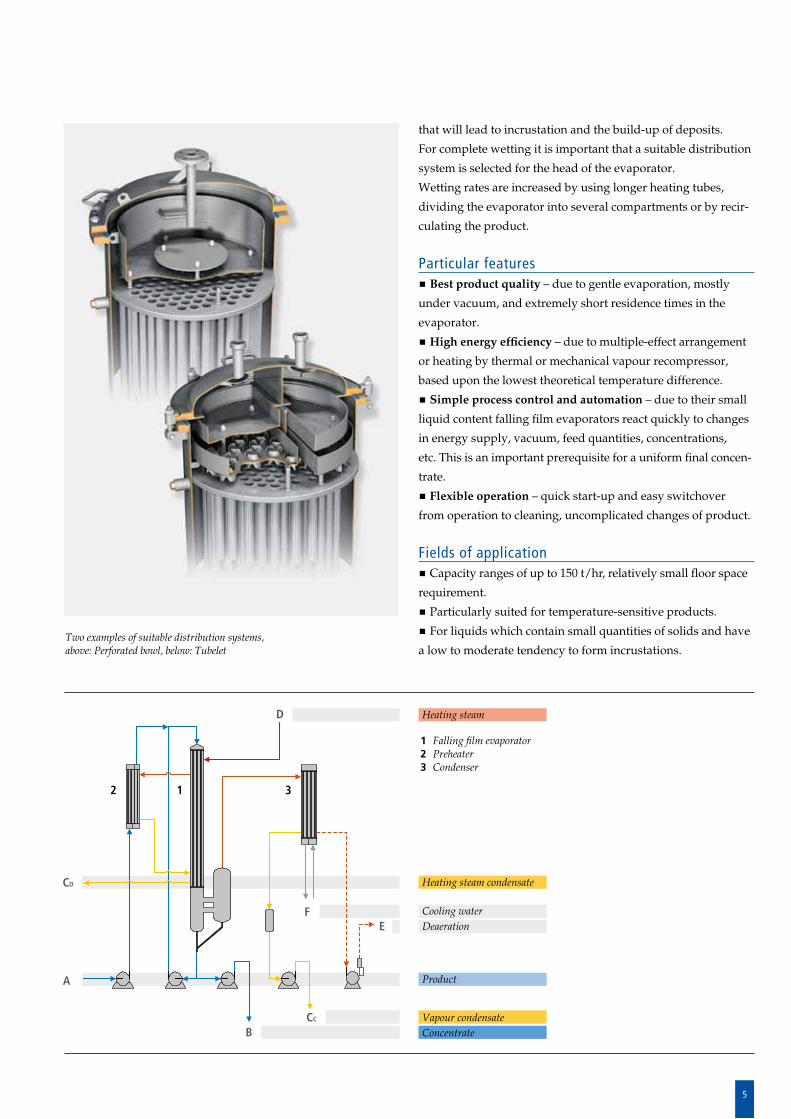
Two examples of suitable distribution systems,above: Perforated bowl, below: Tubelet
Heating steam
Heating steam condensate
Cooling waterDeaeration
Product
Vapour condensateConcentrate
1 Falling film evaporator2 Preheater3 Condenser
A
B
12 3
F
CC
CD
E
that will lead to incrustation and the buildup of deposits.
For complete wetting it is important that a suitable distribution
system is selected for the head of the evaporator.
Wetting rates are increased by using longer heating tubes,
divi ding the evaporator into several compartments or by re c ir
culating the product.
Particular features Best product quality – due to gentle evaporation, mostly
under vacuum, and extremely short residence times in the
evaporator.
High energy efficiency – due to multipleeffect arrangement
or heating by thermal or mechanical vapour recompressor,
based upon the lowest theoretical temperature difference.
Simple process control and automation – due to their small
liquid content falling film evaporators react quickly to changes
in energy supply, vacuum, feed quantities, concentrations,
etc. This is an important prerequisite for a uniform final concen
trate.
Flexible operation – quick startup and easy switchover
from operation to cleaning, uncomplicated changes of product.
Fields of application Capacity ranges of up to 150 t/hr, relatively small floor space
requirement.
Particularly suited for temperaturesensitive products.
For liquids which contain small quantities of solids and have
a low to moderate tendency to form incrustations.
D
6
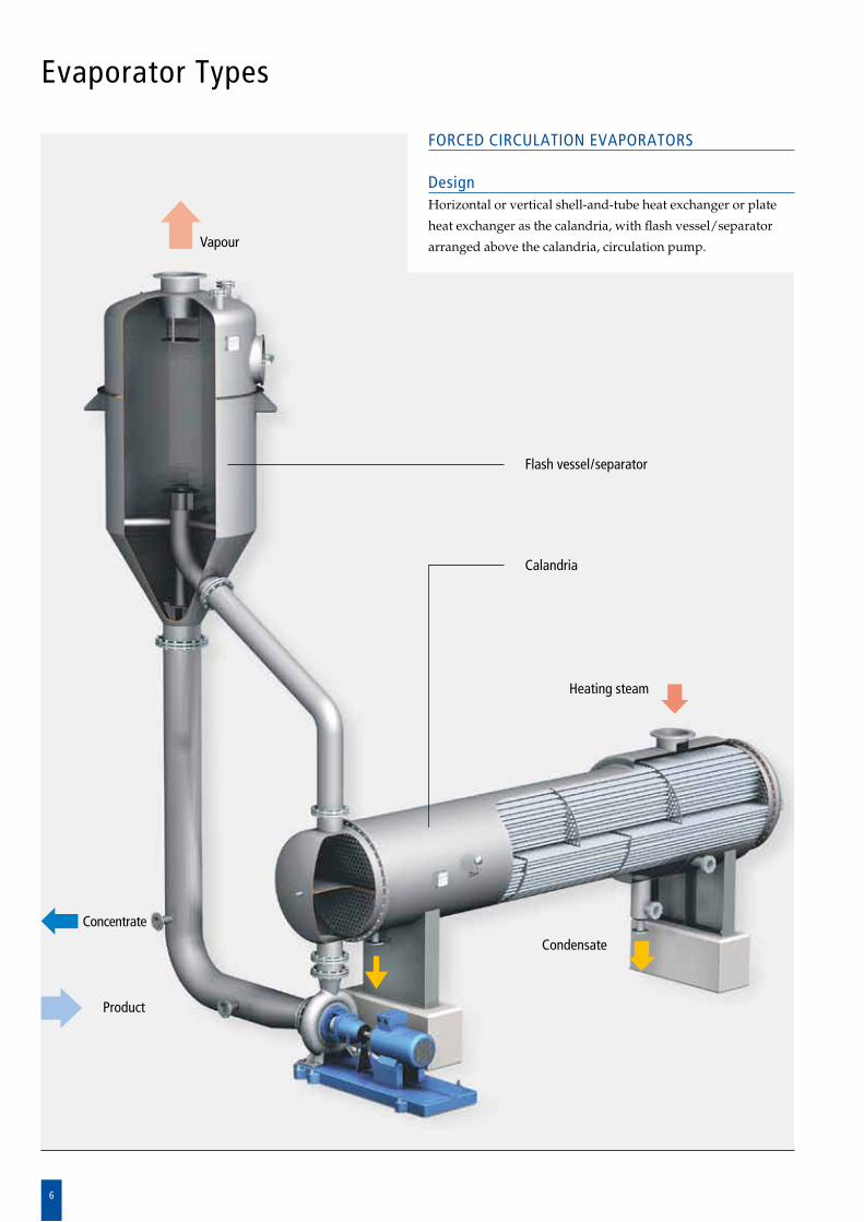
Evaporator Types
FORCED CIRCULATION EVAPORATORS
DesignHorizontal or vertical shellandtube heat exchanger or plate
heat exchanger as the calandria, with flash vessel/sepa rator
arranged above the calandria, circulation pump.Vapour
Heating steam
Condensate
Product
Concentrate
Flash vessel/separator
Calandria
7
CD
AB
CC
D
EF
3
1c1b
2
OperationThe liquid is circulated through the calandria by means of a
circulation pump, where it is superheated at an elevated pres
sure, higher than its normal boiling pressure. Upon entering
the separator, the pressure in the liquid is rapidly reduced
resulting in some of the liquid being flashed, or rapidly boiled
off. Since liquid circulation is maintained, the flow velocity in
the tubes and the liquid temperature can be controlled to suit
the product requirements independently of the preselected
temperature difference.
Particular features Long operating periods – boiling/evaporation does not take
place on the heating surfaces, but in the separator. Fouling due
to incrustation and precipitation in the calandria is therefore
minimised.
Optimised heat exchange surface – flow velocity in the tubes
determined by the circulation pump.
Fields of application Liquids with a high tendency for fouling, highly viscous
liquids, as the high concentration step in multipleeffect eva
poration plants.
Forced circulation evaporators are optimally suited as
crystallising evaporators for saline solu tions.
Heating steam
Cooling waterDeaeration
Vapour condensateHeat. steam cond.ConcentrateProduct
1a Calandria – plate heat exchanger1b Calandria – vertical shell-and-tube heat exchanger1c Calandria – horizontal shell-and- tube heat exchanger2 Separator 3 Condenser
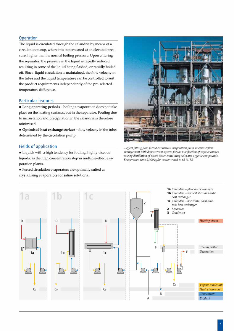
2-effect falling film, forced circulation evaporation plant in counterflow arrangement with downstream system for the purification of vapour conden-sate by distillation of waste water containing salts and organic compounds.Evaporation rate: 9,000 kg/hr concentrated to 65 % TS
1b 1c
D
CDCD
1a
D
1a
8
Evaporator Types
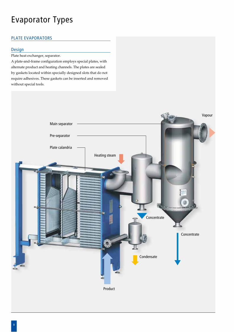
PLATE EVAPORATORS
DesignPlate heat exchanger, separator.
A plateandframe configuration employs special plates, with
alternate product and heating channels. The plates are sealed
by gaskets located within specially designed slots that do not
require adhesives. These gaskets can be inserted and removed
without special tools.
Vapour
Heating steam
Condensate
Product
Concentrate
Concentrate
Main separator
Pre-separator
Plate calandria
9
Heating steam
Cooling water
Deaeration
Vapour condensateHeating steam condensateConcentrateProduct
D
AB
CD
CC
E
F
OperationProduct and heating media are transferred in counterflow
through their relevant passages. Defined plate distances in
con junction with special plate shapes generate strong turbu
lence, resulting in optimum heat transfer.
Intensive heat transfer causes the product to boil while the
vapour formed drives the residual liquid, as a rising film, into
the vapour duct of the plate package. Residual liq uid and
va pours are separated in the downstream centri fugal separator.
The wide inlet duct and the upward movement ensure
op timum distribution over the total crosssection of the heat
ex changer.
Particular features Use of different heating media – due to plate geometries,
the system can be heated with both hot water as well as with
steam.
High product quality – due to especially gentle and uniform
evaporation during singlepass operation.
Little space required – due to compact design, short connec
ting lines and small overall height of max. 3 4 m.
Easy installation requiring little time – due to preassem
bled, transportable construction units.
Flexible evaporation rates – by adding or removing plates.
Ease of maintenance and cleaning – as plate packages can be
easily opened.
Fields of application For low to medium evaporation rates.
For liquids containing only small amounts of undissolved
solids and with no tendency to fouling.
For temperaturesensitive products, for highly viscous
products or extreme evaporation conditions, a product circula
tion design is chosen.
1 Plate calandria2 Separator3 Condenser
2
1 3
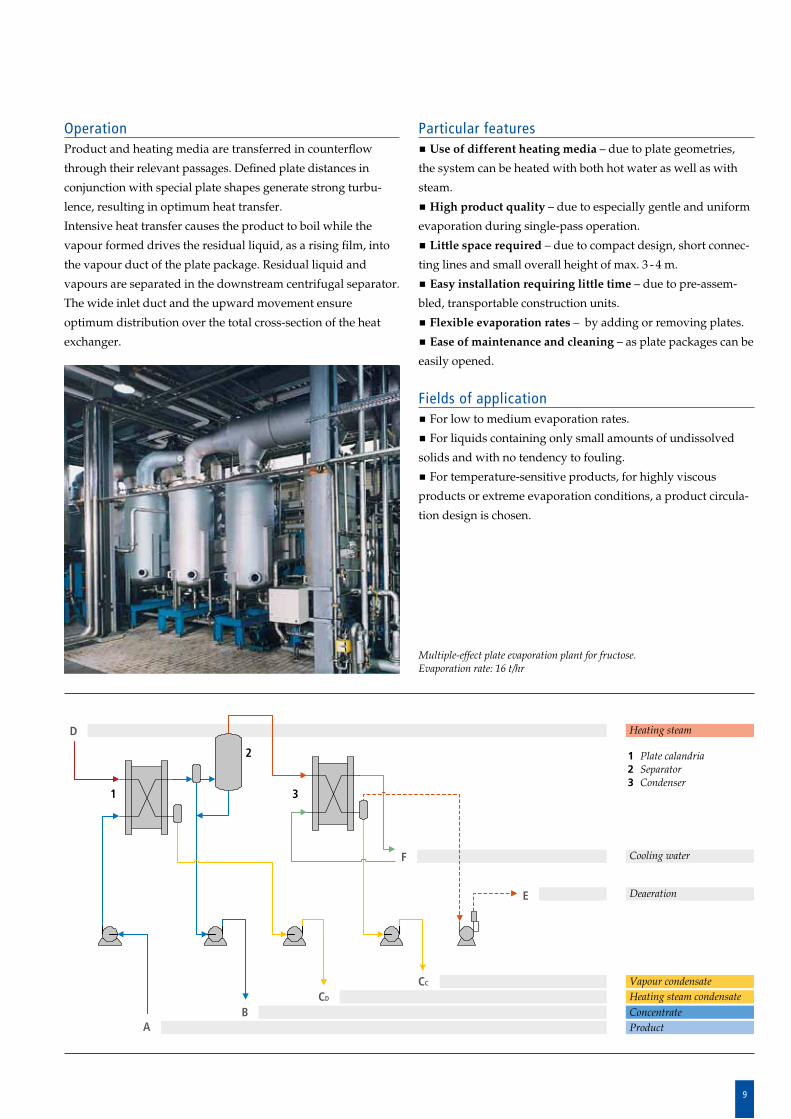
Multiple-effect plate evaporation plant for fructose.Evaporation rate: 16 t/hr
10
Evaporator Types
OperationThe liquid to be concentrated is supplied to the bottom and
rises to the top of the heating tubes in accordance with the
“mammoth pump” or rising film principle. Due to the external
heating of the tubes the liquid film on the inside walls of the
tubes starts to boil releasing vapour. The liquid is carried to
the top of the tubes as a result of the up ward movement of the
vapours.
The liquid is separated from the vapours in the downstream
separator and flows through a circulation pipe back into the
evaporator, ensuring stable and uniform circulation. The larger
the temperature difference between the heating chamber and
the boiling chamber, the greater the intensity of evaporation
and, consequently, the liquid circulation and heat transfer
rates.
Where the boiling chamber of the circulation evaporator is
divided into several separate chambers, each one equipped
with its own liquid circulation system, the heating surface
required for high final concentrations can be considerably
reduced compared to an undivided system.
The final concentration is only reached in the last chamber. In
other chambers, the heat transfer is considerably higher due to
the lower viscosities and boiling point elevations.
CIRCULATION EVAPORATORS
DesignVertical shellandtube heat exchanger of
short tube length, with lateral separator
ar ranged at the top.
Heating steam
DeaerationCooling waterHeating steam condensate
Product
Vapour condensateConcentrate
1 Calandria2 Separator3 Condenser
A
FE
CC
CD
D
2
1
3
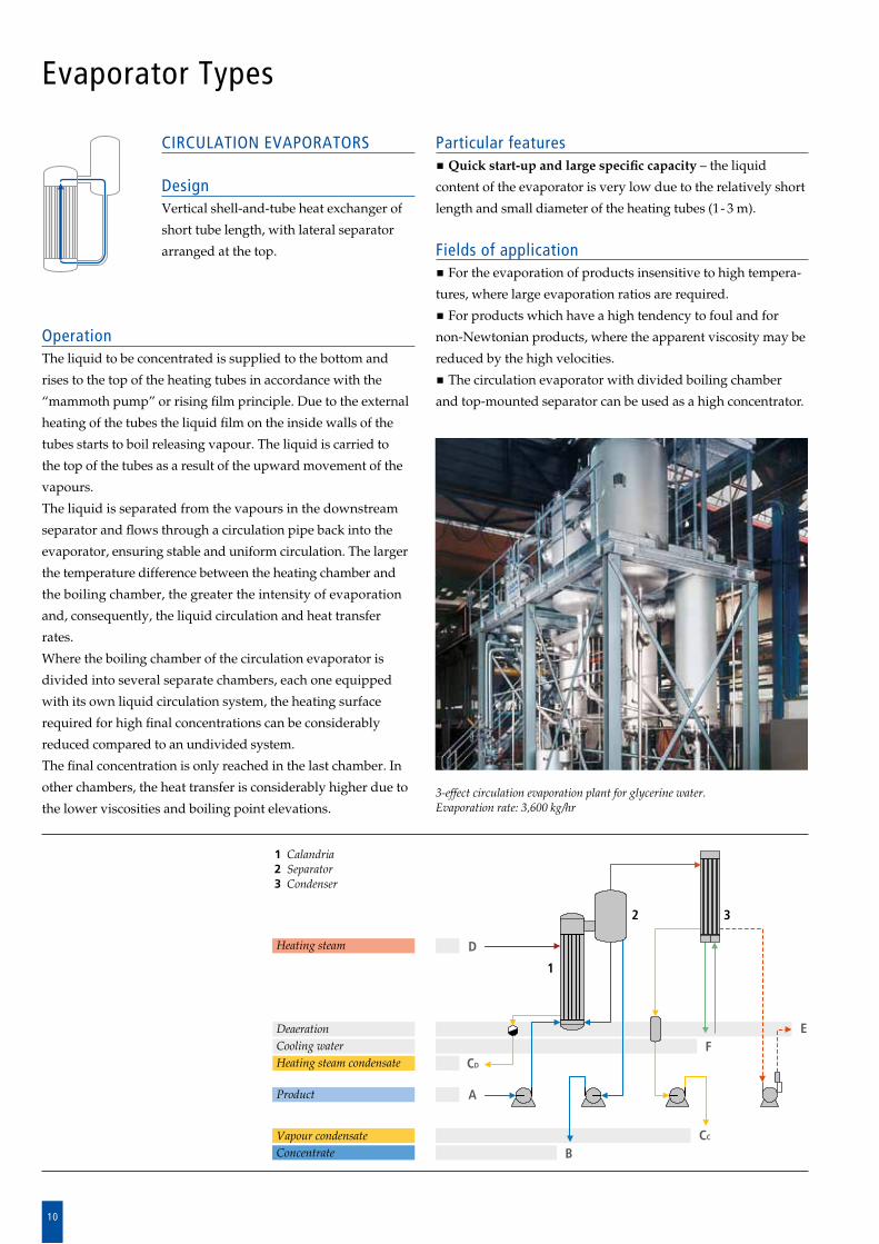
3-effect circulation evaporation plant for glycerine water.Evaporation rate: 3,600 kg/hr
B
Particular features Quick start-up and large specific capacity – the liquid
content of the evaporator is very low due to the relatively short
length and small diameter of the heating tubes (1 3 m).
Fields of application For the evaporation of products insensitive to high tempera
tures, where large evaporation ratios are required.
For products which have a high tendency to foul and for
nonNewtonian products, where the apparent viscosity may be
reduced by the high velocities.
The circulation evaporator with divided boiling chamber
and topmounted separator can be used as a high concentrator.
11
OperationThe liquid is evenly distributed over the heating tubes by
means of a distribution system and flows as a thin film down
the inside walls. The external heating of the tubes causes the
liquid film to boil. The vapours formed are condensed as distil
late on the external walls of the condensate tubes and flow
downwards. Distillate and bottom product are separately kept
and discharged from the lower part of the evaporator.
Particular features Particularly gentle product treatment – due to very low
pressure/temperature processing, short product residence
times and single pass operation. Distillation possible at vacuum
pressures ranging from 1 mbar to below 0.001 mbar. Due to the
integrated condenser tubes, there is no vapour flow pressure
loss.
Optimised design – no mechanical wear and tear, as the
system has no rotating internal parts.
Low investment cost.
Also suitable for high evaporation rates.
Fields of application Particularly temperature sensitive, nonaqueous solutions.
Special Evaporator Types
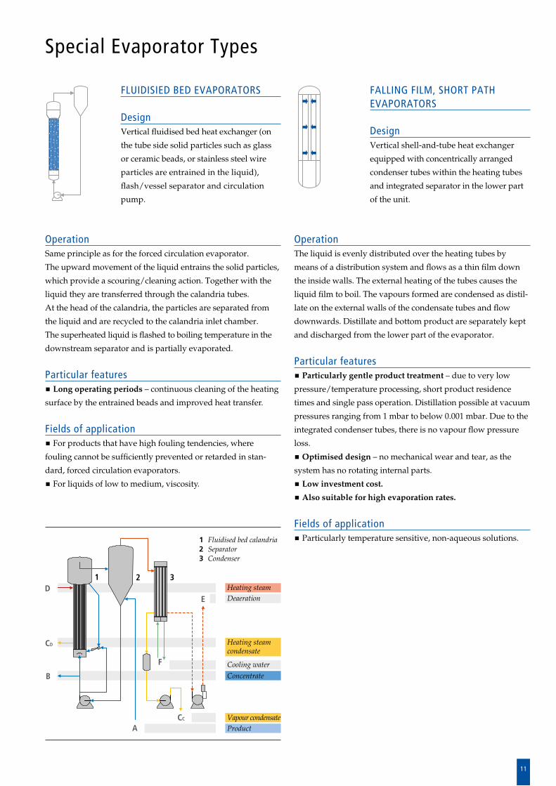
FALLING FILM, SHORT PATH EVAPORATORS
DesignVertical shellandtube heat exchanger
equipped with concentrically arranged
condenser tubes within the heating tubes
and integrated separator in the lower part
of the unit.
FLUIDISIED BED EVAPORATORS
DesignVertical fluidised bed heat exchanger (on
the tube side solid particles such as glass
or ceramic beads, or stainless steel wire
particles are entrained in the liquid),
flash/vessel se parator and circulation
pump.
OperationSame principle as for the forced circulation evaporator.
The upward movement of the liquid entrains the solid particles,
which provide a scouring/cleaning action. Together with the
liquid they are transferred through the calandria tubes.
At the head of the calandria, the particles are separated from
the liq uid and are recycled to the calandria inlet chamber.
The super heated liquid is flashed to boiling temperature in the
downstream separator and is partial ly evaporated.
Particular features Long operating periods – continuous cleaning of the heating
surface by the entrained beads and improved heat transfer.
Fields of application For products that have high fouling tendencies, where
fouling cannot be sufficiently prevented or retarded in stan
dard, forced circulation evaporators.
For liquids of low to medium, viscosity.
Heating steamDeaeration
Heating steamcondensate
Cooling water
Concentrate
Vapour condensateProduct
1 Fluidised bed calandria2 Separator 3 Condenser
A
E
F
B
CC
CD
D21 3
12
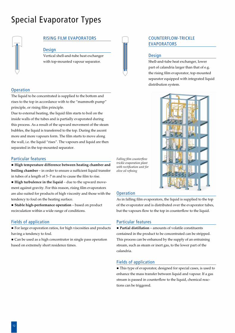
OperationAs in falling film evaporators, the liquid is supplied to the top
of the evaporator and is distributed over the evaporator tubes,
but the vapours flow to the top in counterflow to the liquid.
Particular features Partial distillation – amounts of volatile con stituents
con tained in the product to be concentrated can be stripped.
This process can be enhanced by the supply of an en training
stream, such as steam or inert gas, to the lower part of the
ca lan dria.
Fields of application This type of evaporator, designed for special cases, is used to
enhance the mass transfer between liq uid and vapour. If a gas
stream is passed in counterflow to the liquid, chemical reac
tions can be triggered.
COUNTERFLOW-TRICKLE EVAPORATORS
DesignShellandtube heat exchanger, lower
part of calandria larger than that of e.g.
the rising film evaporator, topmounted
separator equipped with integrated liquid
dis tribution system.
RISING FILM EVAPORATORS DesignVertical shellandtube heat exchanger
with topmounted vapour separator.
Special Evaporator Types
OperationThe liquid to be concentrated is supplied to the bottom and
rises to the top in accordance with to the “mammoth pump”
principle, or rising film principle.
Due to external heating, the liquid film starts to boil on the
in side walls of the tubes and is partially evaporated during
this process. As a result of the upward movement of the steam
bubbles, the liquid is transferred to the top. During the ascent
more and more vapours form. The film starts to move along
the wall, i.e. the liquid “rises”. The vapours and liquid are then
separated in the topmounted separator.
Particular features High temperature difference between heating chamber and
boiling chamber – in order to ensure a sufficient liquid transfer
in tubes of a length of 5 7 m and to cause the film to rise.
High turbulence in the liquid – due to the upward move
ment against gravity. For this reason, rising film evaporators
are also suited for products of high viscosity and those with the
tendency to foul on the heating surface.
Stable high-performance operation – based on product
re circulation within a wide range of conditions.
Fields of application For large evaporation ratios, for high viscosities and pro ducts
having a tendency to foul.
Can be used as a high concentrator in single pass operation
based on extremely short residence times.
Falling film counterflow trickle evaporation plant with rectification unit for olive oil refining
13
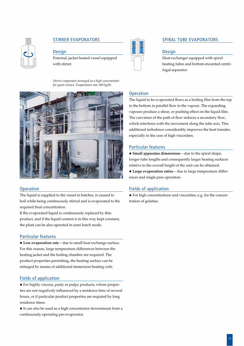
OperationThe liquid to be evaporated flows as a boiling film from the top
to the bottom in parallel flow to the vapour. The expanding
vapours produce a shear, or pushing effect on the liquid film.
The curvature of the path of flow induces a secondary flow,
which interferes with the movement along the tube axis. This
additional turbulence considerably improves the heat transfer,
especially in the case of high viscosities.
Particular features Small apparatus dimensions – due to the spiral shape,
longer tube lengths and consequently larger heating surfaces
relative to the overall height of the unit can be obtained.
Large evaporation ratios – due to large temperature differ
ences and single pass operation.
Fields of application For high concentrations and viscosities, e.g. for the concen
tration of gelatine.
OperationThe liquid is supplied to the vessel in batches, is caused to
boil while being continuously stirred and is evaporated to the
re quired final concentration.
If the evaporated liquid is continuously replaced by thin
pro duct, and if the liquid content is in this way kept constant,
the plant can be also operated in semibatch mode.
Particular features
Low evaporation rate – due to small heat exchange surface.
For this reason, large temperature differences between the
heating jacket and the boiling chamber are required. The
pro duct properties permitting, the heating surface can be
en larged by means of additional immersion heating coils.
Fields of application For highly viscous, pasty or pulpy products, whose proper
ties are not negatively influenced by a residence time of several
hours, or if particular product properties are required by long
residence times.
It can also be used as a high concentrator downstream from a
continuously operating preevaporator.
SPIRAL TUBE EVAPORATORS
DesignHeat exchanger equipped with spiral
heating tubes and bottommounted centri
fugal separator.
STIRRER EVAPORATORS
DesignExternal, jacket heated vessel equipped
with stirrer.
Stirrer evaporator arranged as a high concentrator for yeast extract. Evaporation rate 300 kg/hr
14
Quantities and Concentration Ratios in Evaporation Plants
To calculate continuous evaporation processes, mass
flow rates rather than volumetric quantities are used.
The unit kg/hr is used for A, B and C. The ratios
indicated above do not change.
A C
BInitial concentration cA
of the product flow A kg/hrcA
cB
Evaporated product, concentrate
Final concentration cB
of concentrate flow B kg/hr
The evaporation ratio is a measure for
the concentration process:e The evaporation ratio can also be defined as the ratio of the
initial and final concentrations (% weight dry substance).
Part of the solvent (C), is evaporated from the
product flow (A). The residual amount (B), is
the evaporated product (concentrate):
A = B + C
The evaporated quantity C, can therefore be
defined as the difference between the quantity
of thin solution and concentrate:
C = A – B
Vapour flow C [kg/hr]: Evaporated water,
solvent
e = A = cB
B cA
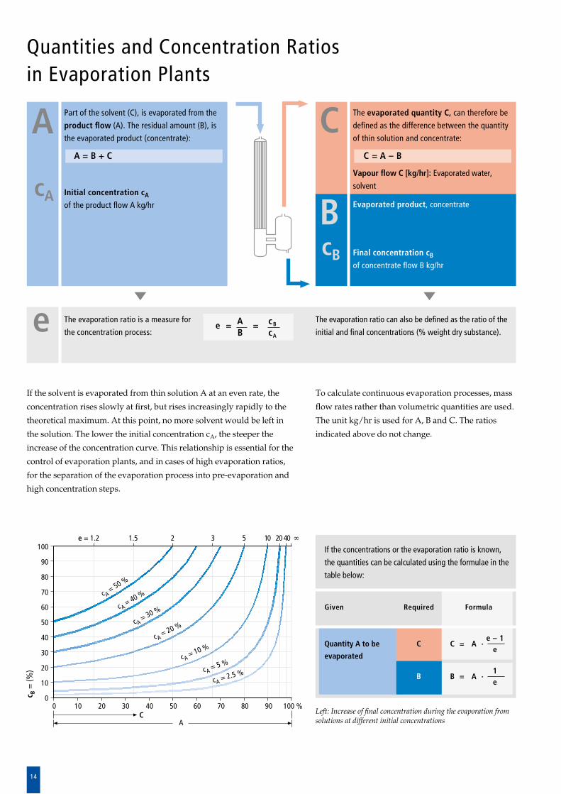
If the solvent is evaporated from thin solution A at an even rate, the
concentration rises slowly at first, but rises increasingly rapidly to the
theoretical maximum. At this point, no more solvent would be left in
the solution. The lower the initial concentration cA, the steeper the
increase of the concentration curve. This relationship is essential for the
control of evaporation plants, and in cases of high evaporation ratios,
for the separation of the evaporation process into preevaporation and
high concentration steps.
Left: Increase of final concentration during the evaporation from solutions at different initial concentrations
Given
Quantity A to be
evaporated
Formula
C = A · e – 1
e
B = A · 1
e
If the concentrations or the evaporation ratio is known,
the quantities can be calculated using the formulae in the
table below:
Required
C
B
15
Energy Efficiency of Evaporation Plants
The operating costs of an evaporation plant are largely deter
mined by the energy consumption.
Under steadystate conditions there must be a balance between
the energy entering and leaving the system.
The energy consumption of the system can be tailored to meet the
customer’s individual requirements by intelligent thermal configura-
tions of the evaporation plant.
There are three basic possibilities to save energy:
Multipleeffect evaporation
Thermal vapour recompression
Mechanical vapour recompression
Application of one of these techniques will considerably de
crease the energy consumption. Often it is feasible to combine
two of these possibilities to minimise capital and operating
costs. In highly sophisticated evaporation plants all three tech
niques may be applied.
5-effect falling film evaporation plant for apple juice concentrate, directly heated, with aroma recovery. Evaporation rate: 12,000 kg/hr
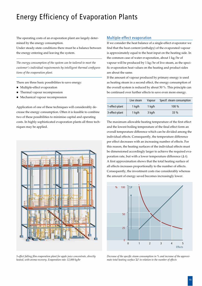
Decrease of the specific steam consumption in % and increase of the approxi-mate total heating surface SF in relation to the number of effects
Multiple-effect evaporationIf we consider the heat balance of a singleeffect evaporator we
find that the heat content (enthalpy) of the evaporated vapour
is approximately equal to the heat input on the heating side. In
the common case of water evaporation, about 1 kg/hr of
vapour will be produced by 1 kg/hr of live steam, as the speci
fic evaporation heat values on the heating and product sides
are about the same.
If the amount of vapour produced by primary energy is used
as heating steam in a second effect, the energy consumption of
the overall system is reduced by about 50 %. This principle can
be continued over further effects to save even more energy.
The maximum allowable heating temperature of the first effect
and the lowest boiling temperature of the final effect form an
overall temperature difference which can be divided among the
individual effects. Consequently, the temperature difference
per effect decreases with an increasing number of effects. For
this reason, the heating surfaces of the individual effects must
be dimensioned accordingly larger to achieve the required eva
poration rate, but with a lower temperature difference (D t).
A first approximation shows that the total heating surface of
all effects increases proportionally to the number of effects.
Consequently, the investment costs rise considerably whereas
the amount of energy saved becomes increasingly lower.
Live steam Vapour Specif. steam consumption
1-effect-plant 1 kg/h 1 kg/h 100 %
3-effect-plant 1 kg/h 3 kg/h 33 %
16
Energy Efficiency of Evaporation Plants
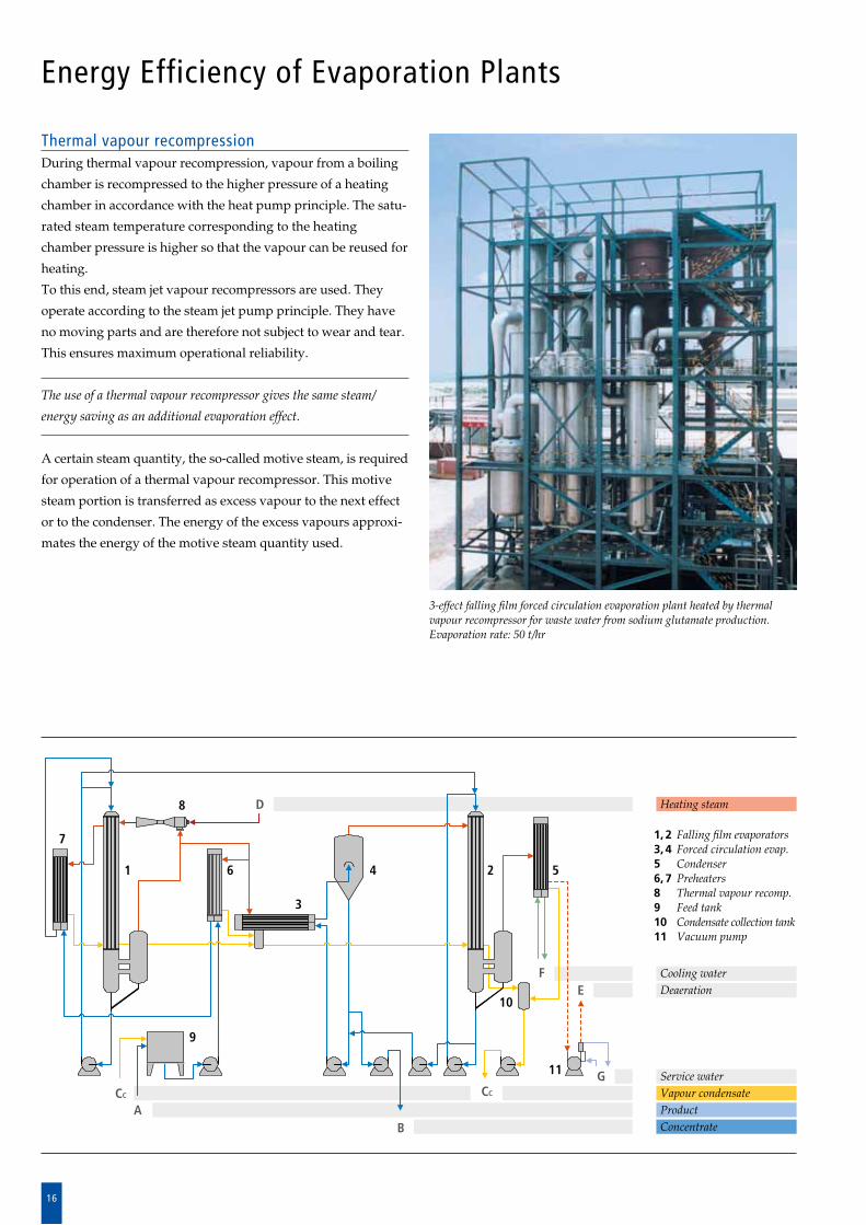
Thermal vapour recompressionDuring thermal vapour recompression, vapour from a boiling
chamber is recompressed to the higher pressure of a heat ing
chamber in accordance with the heat pump principle. The sat u
rated steam temperature corresponding to the heating
chamber pressure is higher so that the vapour can be reused for
heating.
To this end, steam jet vapour recompressors are used. They
operate according to the steam jet pump principle. They have
no moving parts and are therefore not subject to wear and tear.
This ensures maximum operational reliability.
The use of a thermal vapour recompressor gives the same steam/
energy saving as an additional evaporation effect.
A certain steam quantity, the socalled motive steam, is re quired
for operation of a thermal vapour recompressor. This motive
steam portion is transferred as excess vapour to the next effect
or to the condenser. The energy of the excess vapours approxi
mates the energy of the motive steam quantity used.
3-effect falling film forced circulation evaporation plant heated by thermal vapour recompressor for waste water from sodium glutamate production. Evaporation rate: 50 t/hr
Heating steam
Cooling waterDeaeration
Service waterVapour condensateProduct Concentrate
1, 2 Falling film evaporators3, 4 Forced circulation evap.5 Condenser6, 7 Preheaters8 Thermal vapour recomp.9 Feed tank10 Condensate collection tank11 Vacuum pump
1 2
3
4 5
11
6
7
8
9
10
F
D
E
CCCC
BA
G
17
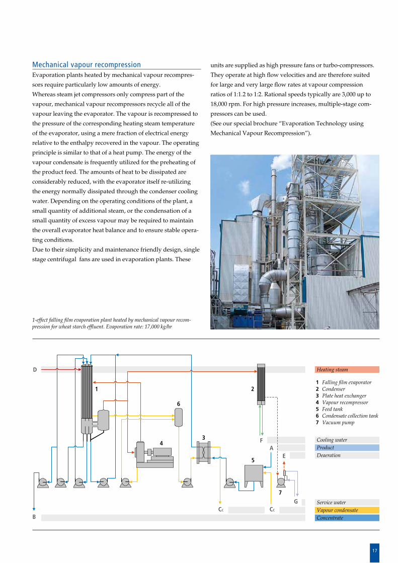
Mechanical vapour recompressionEvaporation plants heated by mechanical vapour recompres
sors require particularly low amounts of energy.
Whereas steam jet compressors only compress part of the
vapour, mechanical vapour recompressors recycle all of the
vapour leaving the evaporator. The vapour is recompressed to
the pressure of the corresponding heating steam temperature
of the evaporator, using a mere fraction of electrical energy
relative to the enthalpy recovered in the vapour. The operating
principle is similar to that of a heat pump. The energy of the
vapour condensate is frequently utilized for the preheating of
the product feed. The amounts of heat to be dissipated are
considerably reduced, with the evaporator itself reutilizing
the energy normally dissipated through the condenser cooling
water. Depending on the operating conditions of the plant, a
small quantity of additional steam, or the condensation of a
small quantity of excess vapour may be required to maintain
the overall evaporator heat balance and to ensure stable opera
ting conditions.
Due to their simplicity and maintenance friendly design, single
stage centrifugal fans are used in evaporation plants. These
units are supplied as high pressure fans or turbocompressors.
They operate at high flow velocities and are therefore suited
for large and very large flow rates at vapour compression
ratios of 1:1.2 to 1:2. Rational speeds typically are 3,000 up to
18,000 rpm. For high pressure increases, multiplestage com
pressors can be used.
(See our special brochure “Evaporation Technology using
Mechanical Vapour Recompression”).
1-effect falling film evaporation plant heated by mechanical vapour recom-pression for wheat starch effluent. Evaporation rate: 17,000 kg/hr
Heating steam
Cooling waterProduct Deaeration
Service waterVapour condensateConcentrate
1 Falling film evaporator2 Condenser3 Plate heat exchanger4 Vapour recompressor5 Feed tank6 Condensate collection tank7 Vacuum pump
AE
B
1 2
34
5
6
7
F
CC
D
GCC
18
Directly heated Thermal vapour recompression
2-effect design
Mechanical vapour recompression
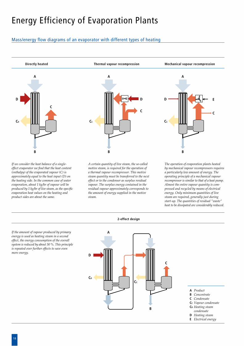
Mass/energy flow diagrams of an evaporator with different types of heating
A
D
B
CD
CC
A
D
B
CD
C
C
D
A
B
CC
C
D
A
B
CC
C
E
A ProductB ConcentrateC CondensateCC Vapour condensateCD Heating steam
condensateD Heating steamE Electrical energy
If we consider the heat balance of a single-effect evaporator we find that the heat content (enthalpy) of the evaporated vapour (C) is ap prox imately equal to the heat input (D) on the heating side. In the common case of water eva poration, about 1 kg/hr of vapour will be pro duced by 1 kg/hr of live steam, as the specific eva poration heat values on the heating and product sides are about the same.
If the amount of vapour produced by primary energy is used as heating steam in a second effect, the energy consumption of the overall system is reduced by about 50 %. This principle is repeated over further effects to save even more energy.
A certain quantity of live steam, the so-called motive steam, is required for the operation of a thermal vapour recompressor. This motive steam quantity must be transferred to the next effect or to the condenser as surplus residual vapour. The surplus energy contained in the residual vapour approximately corresponds to the amount of energy supplied in the motive steam.
The operation of evaporation plants heated by mechanical vapour recompressors requires a particularly low amount of energy. The operating principle of a mechanical vapour recompressor is similar to that of a heat pump. Almost the entire vapour quantity is com -pressed and recycled by means of electrical energy. Only minimum quantities of live steam are re quired, generally just during start-up. The quantities of residual “waste“ heat to be dissipated are considerably reduced.
Energy Efficiency of Evaporation Plants
19
Criteria for the Design Selection, Arrangement and Operating Modes of Evaporation Plants
Evaporation Plant Components
The core of any evaporation plant is the calandria. For the
opera tion of the plant, several additional components are
re quired.
The most important of these are condensers, pre heaters,
pumps, fittings, vents, vacuum systems and cleaning systems.
If substances are to be separated, the plants are also equipped
with rectification columns, membrane filtration units, scrub
bing and aroma recovery systems.
To guarantee troublefree operation of the plant, stateofthe
art measuring, control and computer monitoring systems are
used.
Attention to detail, safety and protective equipment and ther
mal and sound insulation ensure safe operation of the plant.
GEA Wiegand designs, builds and supplies turnkey evaporation
plants. Our experience and expert knowledge of the performance of
each individual component enables us to select the right equipment
for each application so that the requirements of the entire evapora -
tion plant will be met.
Capacity and operating data such as quantities, concentra tions,
temperatures, annual operating hours, change of product,
control, automation.
Product properties such as temperature sensitivity, viscosity
and flow properties, tendency to foaming, fouling and
pre cipitation, boiling properties.
Utility Requirements such as steam, cooling water, electricity,
cleaning agents, parts exposed to wear and tear.
Selection of materials and surface finish.
The most important requirements are as follows:
Capital costs for interest and repayments.
Personnel costs for operation and maintenance.
Site conditions such as space availability, climate for outdoor
installations, connections for energy and product, service
platforms.
Legislative framework regarding health and safety, prevention
of accidents, sound propagation, environmental protection
and others, depending on the specific project.
When designing evaporation plants, various and often contra
dictory requirements must be taken into consideration. These
determine the type of design, arrangement and the resulting
process and cost data.
GEA Wiegand evaporation plants are characterised by their
high quality, efficiency and design refinements. Careful atten
tion is paid to the above mentioned criteria in view of the indi
vidual requirements. In addition, a strong emphasis is placed
on reliability and ease of operation.
20
Evaporation Plant Components
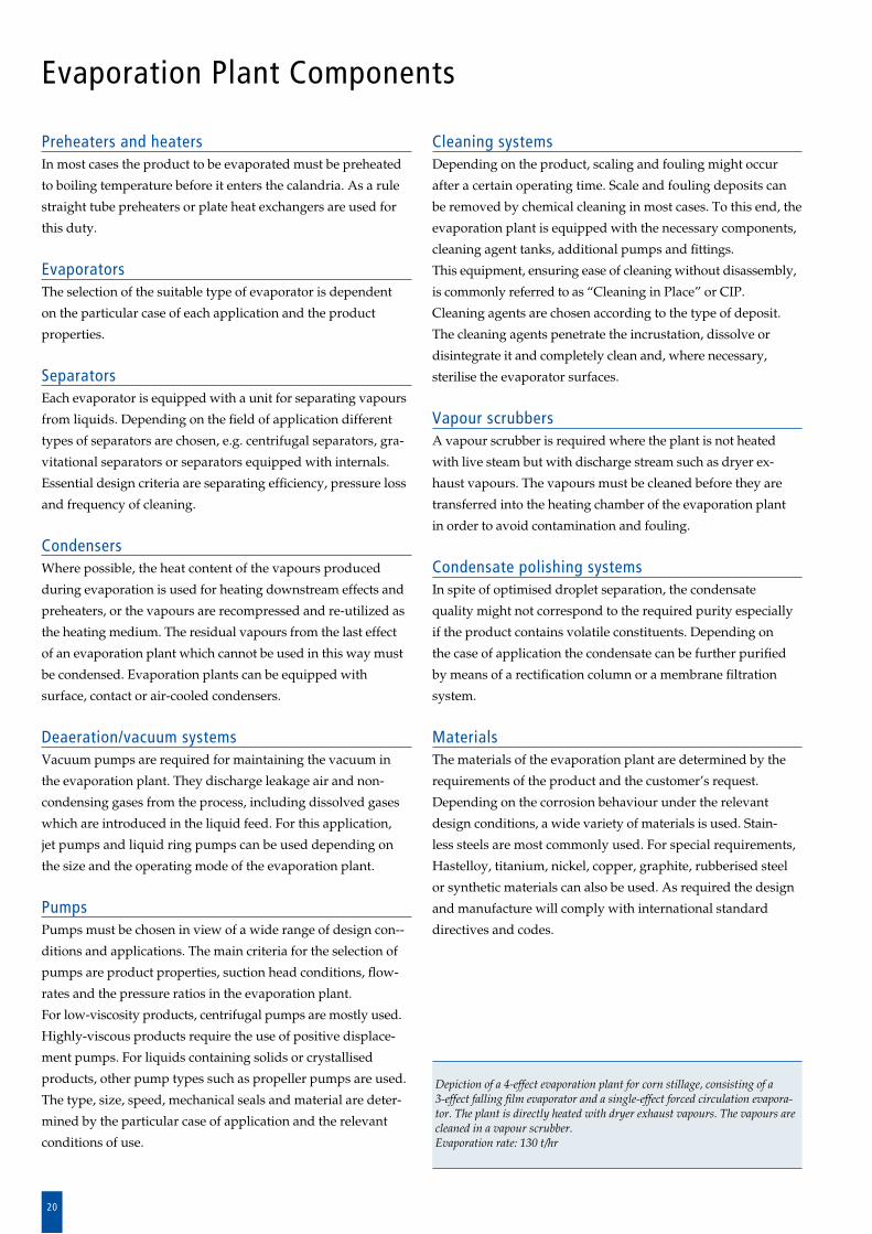
Preheaters and heaters In most cases the product to be evaporated must be preheated
to boiling temperature before it enters the calandria. As a rule
straight tube preheaters or plate heat exchangers are used for
this duty.
EvaporatorsThe selection of the suitable type of evaporator is dependent
on the particular case of each application and the product
pro perties.
Separators Each evaporator is equipped with a unit for separating vapours
from liquids. Depending on the field of application different
types of separators are chosen, e.g. centrifugal separators, gra
vitational separators or separators equipped with internals.
Essential design criteria are separating efficien cy, pressure loss
and frequency of cleaning.
CondensersWhere possible, the heat content of the vapours produced
during evaporation is used for heating downstream effects and
preheaters, or the vapours are recompressed and reutilized as
the heating medium. The residual vapours from the last effect
of an evaporation plant which cannot be used in this way must
be condensed. Evaporation plants can be equipped with
surface, contact or aircooled condensers.
Deaeration/vacuum systemsVacuum pumps are required for maintaining the vacuum in
the evaporation plant. They discharge leakage air and non
con den sing gases from the process, including dissolved gases
which are introduced in the liquid feed. For this application,
jet pumps and liquid ring pumps can be used depending on
the size and the operating mode of the evaporation plant.
Pumps Pumps must be chosen in view of a wide range of design con
ditions and applications. The main criteria for the selection of
pumps are product properties, suction head conditions, flow
rates and the pressure ratios in the evaporation plant.
For lowviscosity products, centrifugal pumps are mostly used.
Highlyviscous products require the use of positive displace
ment pumps. For liquids containing solids or crystallised
products, other pump types such as propeller pumps are used.
The type, size, speed, mechanical seals and material are deter
mined by the particular case of application and the relevant
conditions of use.
Cleaning systemsDepending on the product, scaling and fouling might occur
after a certain operating time. Scale and fouling deposits can
be removed by chemical cleaning in most cases. To this end, the
evaporation plant is equipped with the necessary components,
cleaning agent tanks, additional pumps and fittings.
This equipment, ensuring ease of cleaning without disassembly,
is commonly referred to as “Cleaning in Place” or CIP.
Cleaning agents are chosen according to the type of deposit.
The cleaning agents penetrate the incrustation, dissolve or
disintegrate it and completely clean and, where necessary,
ste rilise the evaporator surfaces.
Vapour scrubbersA vapour scrubber is required where the plant is not heated
with live steam but with discharge stream such as dryer ex
haust vapours. The vapours must be cleaned before they are
transferred into the heating chamber of the evaporation plant
in order to avoid con tamination and fouling.
Condensate polishing systemsIn spite of optimised droplet separation, the condensate
quality might not correspond to the required purity especially
if the product contains volatile constituents. Depending on
the case of application the condensate can be further purified
by means of a rectification column or a membrane filtration
system.
MaterialsThe materials of the evaporation plant are determined by the
requirements of the product and the customer’s request.
Depending on the corrosion behaviour under the relevant
de sign condi tions, a wide variety of materials is used. Stain
less steels are most commonly used. For special requirements,
Hastelloy, titanium, nickel, copper, graphite, rubberised steel
or synthetic materials can also be used. As required the design
and manufacture will comply with international standard
directives and codes.
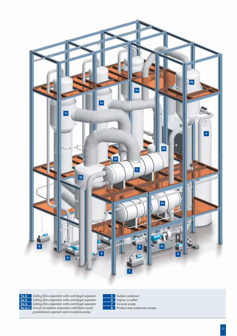
Depiction of a 4-effect evaporation plant for corn stillage, consisting of a3-effect falling film evaporator and a single-effect forced circulation evapora-tor. The plant is directly heated with dryer exhaust vapours. The vapours are cleaned in a vapour scrubber.Evaporation rate: 130 t/hr
21
1a
2a
3a
4b
6
3b
5
2b
1b
4a
4c
8
8
88
8
7
1a,b Falling film evaporator with centrifugal separator2a,b Falling film evaporator with centrifugal separator3a,b Falling film evaporator with centrifugal separator4a,b,c Forced circulation evaporator with flash vessel/
gravitational separator and circulation pump
5 Surface condenser6 Vapour scrubber7 Vacuum pump8 Product and condensate pumps
22
Measuring and Control Equipment
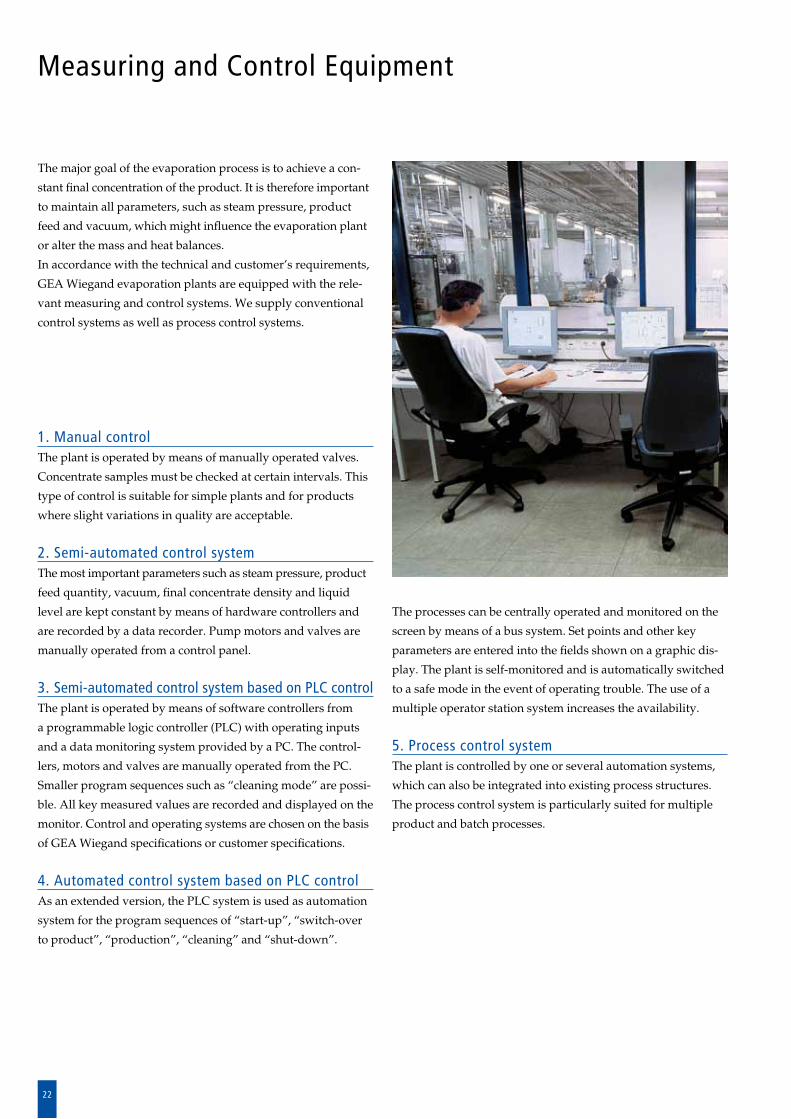
The major goal of the evaporation process is to achieve a con
stant final concentration of the product. It is therefore important
to maintain all parameters, such as steam pressure, pro duct
feed and vacuum, which might influence the evaporation plant
or alter the mass and heat balances.
In accordance with the technical and customer’s requirements,
GEA Wiegand evaporation plants are equipped with the rele
vant measuring and control systems. We supply conventional
control systems as well as process control systems.
1. Manual controlThe plant is operated by means of manually operated valves.
Concentrate samples must be checked at certain intervals. This
type of control is suitable for simple plants and for products
where slight variations in quality are acceptable.
2. Semi-automated control systemThe most important parameters such as steam pressure, product
feed quantity, vacuum, final concentrate density and liquid
level are kept constant by means of hardware controllers and
are recorded by a data recorder. Pump motors and valves are
manually operated from a control panel.
3. Semi-automated control system based on PLC controlThe plant is operated by means of software controllers from
a pro grammable logic controller (PLC) with operating inputs
and a data mo n itoring system provided by a PC. The control
lers, motors and valves are manually operated from the PC.
Smaller program se quences such as “cleaning mode” are possi
ble. All key measured values are recorded and displayed on the
monitor. Control and ope rating systems are chosen on the basis
of GEA Wiegand specifications or customer specifications.
4. Automated control system based on PLC controlAs an extended version, the PLC system is used as automation
system for the program sequences of “startup”, “switchover
to product”, “production”, “cleaning” and “shutdown”.
The processes can be centrally operated and monitored on the
screen by means of a bus system. Set points and other key
parameters are entered into the fields shown on a graphic dis
play. The plant is selfmonitored and is automatically switched
to a safe mode in the event of operating trouble. The use of a
multiple operator station system increases the availability.
5. Process control systemThe plant is controlled by one or several automation systems,
which can also be integrated into existing process structures.
The process control system is particularly suited for multiple
product and batch processes.
23
Project Management, Commissioning and After-Sales Service
Our scope of services starts with engineering and ends up
with delivery, erection, commissioning and aftersales service
just upon your request.
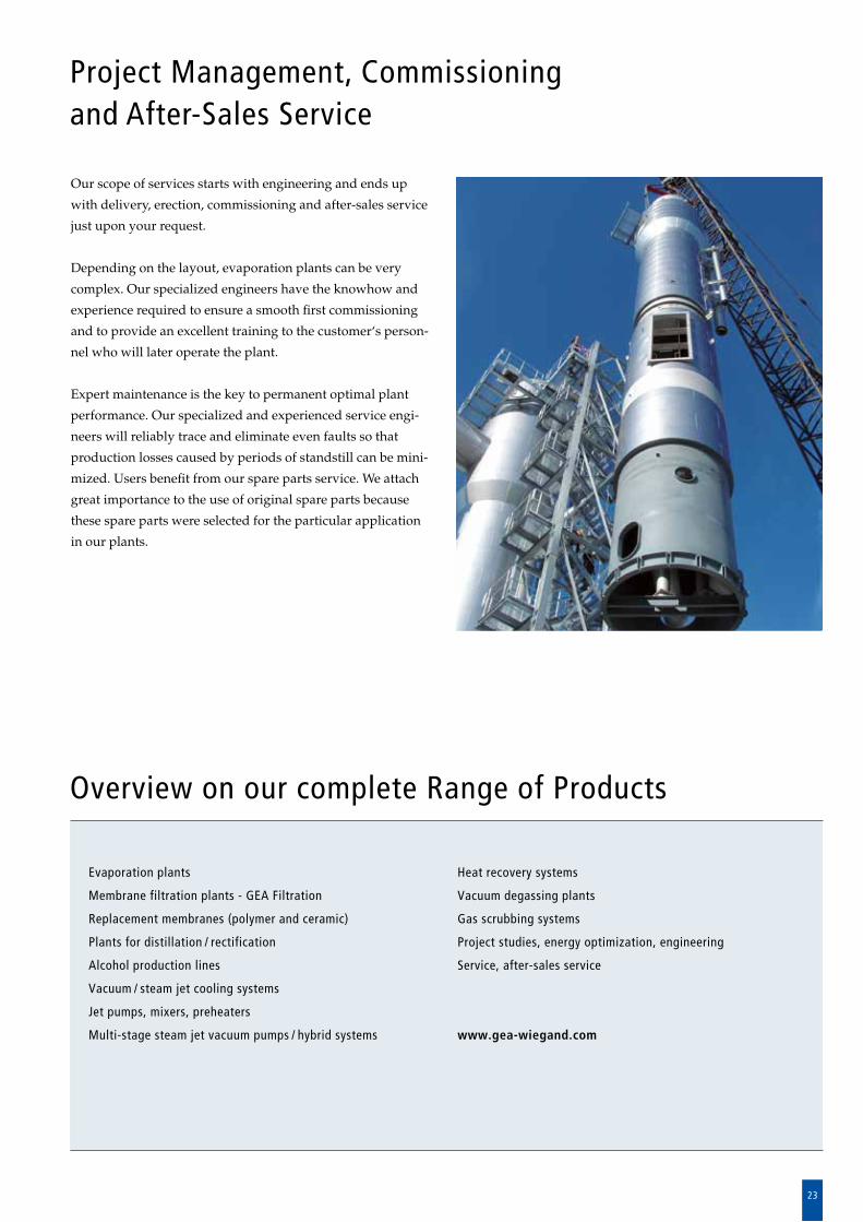
Depending on the layout, evaporation plants can be very
complex. Our specialized engineers have the knowhow and
experience required to ensure a smooth first commissioning
and to provide an excellent training to the customer‘s person
nel who will later operate the plant.
Expert maintenance is the key to permanent optimal plant
performance. Our specialized and experienced service engi
neers will reliably trace and eliminate even faults so that
production losses caused by periods of standstill can be mini
mized. Users benefit from our spare parts service. We attach
great importance to the use of original spare parts because
these spare parts were selected for the particular application
in our plants.
Overview on our complete Range of Products
Evaporation plants
Membrane filtration plants - GEA Filtration
Replacement membranes (polymer and ceramic)
Plants for distillation / rectification
Alcohol production lines
Vacuum / steam jet cooling systems
Jet pumps, mixers, preheaters
Multi-stage steam jet vacuum pumps / hybrid systems
Heat recovery systems
Vacuum degassing plants
Gas scrubbing systems
Project studies, energy optimization, engineering
Service, after-sales service
www.gea-wiegand.com
© G
EA W
iega
nd G
mbH
. All
right
s re
serv
ed. P
03E
1220
14 HINKEL360
GEA Process Engineering
GEA Wiegand GmbH
Am Hardtwald 1, 76275 Ettlingen, GermanyPhone: +49 7243 705-0, Fax: +49 7243 [email protected]
GEA Group is a global engineering company with multi-billion euro sales and operations in more than 50 countries. Founded in 1881, the company is one of the largest providers of innovative equipment and process technology. GEA Group is listed in the STOXX® Europe 600 Index.
We live our values.Excellence • Passion • Integrity • Responsibility • GEA-versity