Automotive Aftermarket Boîtes de vitesses / Embrayage Gearbox ...

1
Endurance testing of automotive gearbox
Ing. Ondřej Miláček
Supervisor: Doc.Dr.Ing. Gabriela Achtenová
Abstract The presentation will deal with the lifetime of gears, the theories of linear accumulation of fatigue damage and various types of tests. The presentation deals with the methodology of one-level tests, general principles of open and closed test bench, the specific description of the test bench in the laboratory of the CTU in Prague - the possibility of using the planet pre-tensioning mechanism for the realization of the load spectrum torque change which is used in Juliska laboratories. Keywords Gearbox, HCR gear, endurance test, closed loop stand, equivalent load torque, linear damage accumulation, pitting
1. Introduction In car gearboxes there are very often used teeth with a non-standard tooth profile. It has been proved by means of extensive researches and frequent applications, that the involute gearing with high contact ratio has much better properties in comparison with standard tooth forms. In this paper, the basic principle of HCR gear is performed, which is characterized by integer coefficient of transverse contact ratio at helical teeth. The limitations of this gearing are mentioned and the basic defects during the realizations are defined.
2. Involute gear geometry Involute is a curve which arises by generating of a line around a circle. In case o gearwheels so called “base circle” (db). nb dd αcos⋅= (1)
d…pitch diameter
Also two gearwheels that are in a mesh are touching only along the line – so called “mesh line” – in the figure 1. from the point A to the point E. Figure 1 shows the basic geometry parameters of the standard involute gear in the transverse plane.

2
Fig. 1. Profile of standard involute gear in transverse plane
The meaning of the transverse contact ratio is evident from following fig.2.
Fig. 2. Parameters of involute gear
and is given with the equation (2). By standard gear is εα< 2.
(2) By standard involute gear the value of the mesh angle in normal plane is αn = 20°. The second very important parameter of the gear set is the overlap ratio εεεεββββ. The meaning of this parameter is explained in the figure 3. Its value can be count by using formula (2). Without greater limitations, the integer overlap ratio εβ can be designed very easily, when suitable angle β and tooth width b are selected

3
Fig. 3. Overlap ratio
.
(2)
3. HCR gear geometry (High Contact Ratio) HCR gears are usually used in car gearboxes. This is possible due to the amount of these gearwheels that are produced in great series. Also, it is possible to manufacture a special instrument for cutting these gearwheels. The standard procedures for load capacity calculating of gears are in most cases normalized for gears with standard profile. There is written that standard can be used only for gears with contact ratio εεεεαααα < 2 in Czech standard ČSN [1]. There is included non-standard shape of teeth only for calculating stiffness and strength in standards ISO [2] and DIN [3]. The gearing HCR with integer contact ratio εεεεαααα = 2 has another properties then gearing formed with the standard shape profile. Basic differences are in figure 1.
Fig. 4 . Differences between standard(left picture) and HCR (eα = 2) cylindrical gearset
4
There are shown mesh fields for cylindrical gears. While two or one teeth pair in contact are changing at mesh of the standard gear, two teeth pairs are permanently in contact at mesh of HCR gear with εεεεαααα = 2. Advantages of HCR gear with εεεεαααα = 2 are based on smoother change of stiffness at mesh and smooth dividing of total carried force between two teeth pairs. When parameters are changed according to tab. 1, there exist some limitations, because the toothed gearing properties are deteriorated or its function is lost. The main risks are as follows: - too small tooth thickness on the pinion head - undercutting the pinion tooth dedendum - inadmissible increase of relative slidings (note: in order to minimize the relative slidings, it is useful to select the addendum modification coefficients for their equalizing)
Table 1. Influence of basic spur gear parameters on contact ratios
In table 2, the changes of parameters are shown according to tab. 1, which reduce (increase) the risks.
Table 2. Influence of basic spur gear parameters on the risks limiting its function
5
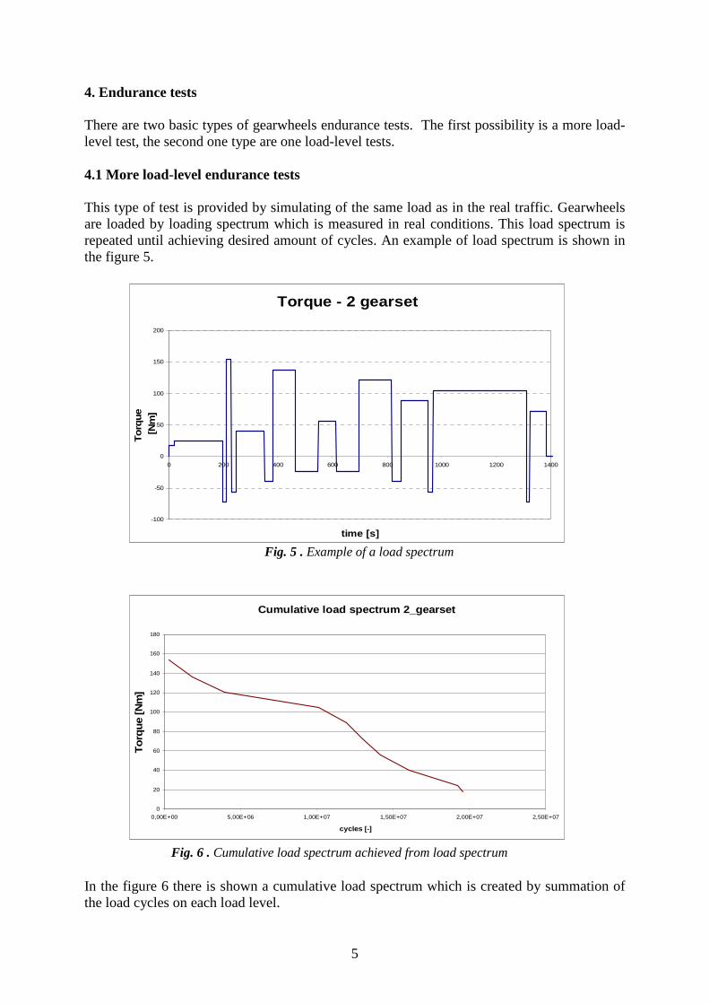
4. Endurance tests There are two basic types of gearwheels endurance tests. The first possibility is a more load-level test, the second one type are one load-level tests. 4.1 More load-level endurance tests This type of test is provided by simulating of the same load as in the real traffic. Gearwheels are loaded by loading spectrum which is measured in real conditions. This load spectrum is repeated until achieving desired amount of cycles. An example of load spectrum is shown in the figure 5.
Fig. 5 . Example of a load spectrum
Fig. 6 . Cumulative load spectrum achieved from load spectrum In the figure 6 there is shown a cumulative load spectrum which is created by summation of the load cycles on each load level.
Torque - 2 gearset
-100
-50
0
50
100
150
200
0 200 400 600 800 1000 1200 1400
time [s]
To
rque
[N
m]
Cumulative load spectrum 2_gearset
0
20
40
60
80
100
120
140
160
180
0,00E+00 5,00E+06 1,00E+07 1,50E+07 2,00E+07 2,50E+07
cycles [-]
To
rqu
e [N
m]

6
q k
xii
k
xii
qi
E
n
nMM
∑
∑
=
=
⋅=
4.2 One load-level endurance tests One load-level tests are provided mostly as a comparative test to more load-level tests. This whole method is based on an idea that the gear set is loaded only at one load level which causes same damage DC as the whole real more load-level spectrum. This load-level is called as equivalent load (torque, strength). This load is defined by a formula 3. (3)
i……..index of load level M i ….torque at each level ni…….amount of cycles at each level q……..exponent of S-N curve
Example of an equivalent torque achieved from a load spectrum is shown in the figure 7 by red line at the level 125 Nm.
Fig. 7. Load spectrum and its equivalent torque
Very positive on this kind of test is that it is possible to use overloading. An appropriate overloading is possible without exceeding the maximal allowed torque. Maximal recommended overloading is approximately 25%. By higher overloading there arises a problem with bending of the shafts which has major influence at the parameters in the mesh.
Torque 2 gearset
-100
-50
0
50
100
150
200
0 200 400 600 800 1000 1200 1400
time [s]
To
rqu
e [N
m]

7
5. Linear damage accumulation (DC) hypotheses Each gear set is designed for specific type of load spectrum. At the load spectrum can be evaluated fullness and aggressiveness. These properties are explained in figure 8.
Fig. 8. Fullness and aggressiveness of the load spectrum
Fig. 9. Linear damage accumulation (DC) hypotheses Miner´s hypothesis is recommended for spectra with high aggressiveness, Haibach’s hypothesis is recommended for spectra with low aggressiveness, and Corten-Dolan’s is recommended for spectra with low fullness.
Aggressiveness High Low Fullness
High Low
Fatigue limit
Miner
Haibach
Corten-Dolan

8
6. Scheme and principle of the closed loop stand So called closed stands are commonly used due to energy saving. Scheme of such a stand is shown in the picture 10.
Fig. 10. Scheme of a closed loop stand
These stands work at the principle of power circulation. The load torque is evoked by turning the shafts also we need energy just for overruling of passive resistances. The gear lifetime test are very time demanding and so the power saving is a very important aspect. In this closed loop, there have to be two identical gear sets. One of them is the tested one while the second one is only technological – for closing the loop. See figure 10.
Fig. 11. Scheme of power flow in closed loop stand.
In picture 11, there is shown a scheme of power flow with circulation in such a closed loop. The direction of the power flow depends on the direction of turning and pre-tensioning. In this figure there is shown only power loss PfA1 and PfA2 . These two losses are simulating bearings and friction in gear mesh and heat loss. There are not included power losses in jointed shafts which connect these two gearboxes. It is evident from this scheme that one gearbow is more loaded than the second one. The more loaded gearbox is the tested one (A1).
Tested gear Technological
gear

9
In our laboratory at Juliska, CTU in Prague is such a kind of closed loop testing stand which was designed on TU in Ostrava for testing of the gearboxes for Skoda, a.s.. The advantage of the testing stand is that the placement of the gearbox is the same as in a real car – see figure 12. This stand allows to provide one load-level tests. The pre-tensioning mechanism with the worm gear is shown in the figure 13.
Fig. 12. Closed bench in the laboratory at Juliska at CTU in Prague
Fig. 13. Pre-tensioning mechanism with the warm gear for one load level tests,
laboratory at Juliska at CTU in Prague If there is instead of this worm gear used a pre-tensioning mechanism with the planetary gear set, it is possible to provide also more load-level endurance tests.
Fig. 14. Pre-tensioning mechanism with the warm gear for one load level tests,
laboratory at Juliska at CTU in Prague

10
Scheme and principle of this planetary gear set with two degrees of freedom is shown in the figure 14 and the real design is shown in the figure 15.
Fig. 15. Pre-tensioning mechanism with the warm gear for one load level tests,
laboratory at Juliska at CTU in Prague 7. Results of the endurance tests There are two possible damages of the gears – pitting or breakage. As a result of our testing we have received following data. The equivalent torque to the spectrum was MEH=124,7Nm. After 96 hours, the pitting appeared in the tested gear set which was the aim of our test. See picture 16.
Fig. 16. Pitting at the tested gearwheel after 96 hours
8. Conclusion The best kind of a gear set testing are more level tests because they are very good simulating the real load spectrum. One load endurance tests are commonly used as comparative tests loaded with an equivalent torque which causes same damage as the whole load spectrum. The loading is not same as in real car but with overloading can be achieved markable shortening of the tests.

11
List of Abbreviations
I index of load level [-] M i torque at each level [Nm] ni amount of cycles at each level [-] q exponent of S-N curve [-] d pitch diameter [mm] db base diameter [mm]
Bibliography [1] ČSN 01 4686: Pevnostní výpočet čelních a kuželových ozubených kol. [2] ČSN-ISO 6336: Výpočet únosnosti čelních ozubených kol s přímými a šikmými zuby (návrh). [3] DIN 3990: Tragfähigkeitsberechnung von Stirnrädern. [4] Horyl P. (2001). Numerická studie kontaktních tlaků pro nestandardní ozubení. ICESA, Ostrava. [5] Havlík T. (2005). Teze k rigorózní zkoušce: Pevnostní výpočet soukolí HCR. Ostrava. [6] Havlík T. (2003). Diplomová práce: Vliv geometrických odchylek tvaru na mechanické
namáhání zubu ozubeného kola. VŠB-TU Ostrava. [7] Linke H. (1996). Stirnradverzahnung. Berechnung. Werkstoffe. Fertigung. Karl Hanser Verlag München, Vien. [8] Miller, R.: Schwingungs – und Geräuschanregung bei Stirn-radgetrieben. Dissertation, 1990,Technische Universität München. [9] Moravec V. (2001). Výsledky únavových běhových zkoušek evolventního ozubeného
soukolí s prodlouženým trváním záběru profilu . Výzkumná zpráva VŠB-TU Ostrava č.11 –CEZ č.J17/98-347, Ostrava.
[10] Moravec V. (2004). Návrh programu běhových zkoušek ozubení HCR s počty zubů 21/51 a 35/37. Katedra 347, VŠB-TU Ostrava. [11] Němček M. (2003). Vybrané problémy geometrie čelních ozubených kol, Montanex a.s., Ostrava.