EnDuraLast 450w Charging System Installation Guide · EnDuraLast 450w Charging System Installation...
32
EnDuraLast 450w Charging System Installation Guide Table of Contents Product Overview/Warranty Page 2-7 Kit Contents Page 5 Mechanical Installation of Components Page 7 Electrical Installation of Charging System Page 18 Electrical Wiring Connections Page 20 Testing Charging System Page 28 Typical Regulator/Rectifier Install Locations Page 32 Thank you for your purchase! This kit, when properly fitted, is extremely reliable and efficient. Please read the installation guidelines carefully. For clearer images, download the .pdf file from our website. To view these installation instructions online visit our website and search for “EDL450-ALTKIT” in the search box. You will then need to click the product link and click the “Extended Info” tab.
Transcript of EnDuraLast 450w Charging System Installation Guide · EnDuraLast 450w Charging System Installation...

EnDuraLast 450w Charging SystemInstallation Guide
Table of ContentsProduct Overview/Warranty Page 2-7Kit Contents Page 5Mechanical Installation of Components Page 7Electrical Installation of Charging System Page 18Electrical Wiring Connections Page 20Testing Charging System Page 28Typical Regulator/Rectifier Install Locations Page 32
Thank you for your purchase!This kit, when properly fitted, is extremely reliable and efficient. Please read the installation guidelines carefully. For clearer images, download the .pdf file from our website. To view these installation instructions online visit our website and search for “EDL450-ALTKIT” in the search box. You will then need to click the product link and click the “Extended Info” tab.
Page 2 www.euromotoelectrics.com
Original Equipment NewNew Permanent Magnet Rotor, Brushless Design
EnDuraLast Alternator Kit 29 Amps / 400 Watts @ 5000 RPM (450 Watts Total Max Rating)
25 Amps / 350 Watts @ 3000 RPM 20 Amps / 280 Watts @ 2000 RPM
• Increases amperage by up to 80% over stock Bosch systems
• Stable voltage production under all load conditions• Electronic voltage regulator/rectifier combination remotely
mounted for increased cooling and reliability, replaces diode board rectifier
• High-tech permanent magnet rotor will never overheat or short out
• Brushless design eliminates worn out rotor slip rings and brushes
• Eliminates “burnt out warning light” no-charge condition of Bosch systems
• Will retrofit all BMW R Airhead applications between 1970-1995 and Moto Guzzi 1975-1992, bolts right on and wires up simply
• Designed and manufactured to modern OEM specifica-tions

Page [email protected]
Warranty This kit is warranted from defects in material and workmanship for 1 year from date of purchase. Due to the cooling requirements of the Rectifier/Regulator unit, installation of this unit must be documented with photos for warranty claims. Euro MotoElectrics disclaims all other warranties, either expressed or implied. This includes any implied warranty of merchantability of fitness for a non-specific use, and neither assumes nor authorizes any other person or professional installer to assume for it any liability in connection with the sale of this product, or for any consequen-tial damages or incidents arising from its use. Any unauthorized modifications or substitutions to the system components will void the warranty.
Notes & Disclaimers:• The components of this kit are manufactured by a major original
equipment charging system parts manufacturer and adapted for fitment to BMW R-Series and Moto Guzzi motorcycles. The com-ponents were computer tested prior to being shipped from the ISO certified factory. They are a matched set in terms of electro-me-chanical electrical production and electronic voltage regulation, as well as AC / DC rectification. Do not drill or modify the Rectifier / Voltage Regulator. Any unauthorized modifications or substitutions to the system components will void the warranty.
• The installation of this charging system assumes the installing technician has basic mechanical and electrical skills. Please understand the intricacies of working on 10-35 year old vehicles may require additional work to the wiring and fitment of this kit not specifically covered in the below guidelines.
• Due to the variety of motorcycles to which this kit can be fitted, it is not possible to cover all the potential options for alternative rectifier/regulator mounting and wiring. The included instructions cover most BMW motorcycles. Special notes for Moto Guzzi bikes or specific BMW years/models are made when available, but are NOT to be considered all-inclusive. When your model is not covered, use these instructions as a guideline for proper mounting/wiring procedures.
• Develop an installation plan prior to initiating your retrofitment, with special focus to mounting the rectifier / regulator module {item 1}.
• IMPORTANT: Read through this set of installation instructions completely and make sure you understand all steps to be per-formed prior to starting any work !

Page 4 www.euromotoelectrics.com
Before beginning work, confirm that youhave the correct stator frame diameter:
Bosch Alternator # Stator Frame Size (Diameter mm)
0 120 340 001 1050 120 340 002 1050 120 340 003 1050 120 340 004 1070 120 340 005 1070 120 340 006 1050 120 340 008 107
There may be some cross-over on BMW applications;so please be careful!
BMW 1970-1976 ~ 105mmBMW 1974-1975 ~ 105mm or 107mmBMW 1976-1995 ~ 107mm Moto Guzzi – ALL: 105mm
If label is not there you can measure the stator frame where it inserts into the timing chain cover. (see Mech. Assy. instructions step #25)
After Installation:Do not overload the system! Although you will have dramatically increased your wattage amperage output, you must still observe the laws of physics and electromagnetism. Please review the watt-age demands of all additional accessories prior to installation and / or use. To protect the reliability of the charging system, there should be a 10-20% buffer margin between demand and output capacity at your engine operating speed. { Refer to charge system output chart on page 2 } Total wattage demand should NEVER exceed the wattage capac-ity of the system. The original equipment Bosch charging system needs to have an operating charge warning light because the rotor field excitation current is initiated thru the warning lamp circuit. If the charge lamp is burnt out, the rotor does not get any startup current, so no charging occurs. The EnDuraLast system uses a permanent magnet rotor and needs no excitation current. So, unlike the original charging system, the condition of the charge warning lamp has no effect on the operation of the EnDuraLast charging system.

Page [email protected]
Kit Contents:
1. Rectifier / Voltage Regulator2. Rear Stator Frame3. Stator Windings4. Front Stator Frame5. Rotor6. Rotor Attachment Bolt, M8 7. Locking Washer, M8 (may be
already on rotor)8. Rotor Removal Drift Pin Tool9. Rectifier/Regulator Lower
Mounting “L” Bracket10. 3/4”x1”dia. Pipe Strap11. Rectifier/Regulator Upper
Mounting Stud, M6 Coupling Nut
12. Wire Clamp13. Locking Washers, M514. Stator Frame Screws15. Dielectric Grease16. EME Sticker17. M6 Flat Washer18. M6 Lock Washer
19. M6 Hex Nut20. M5x25mm Socket Head Cap
Screw21. M6 x 16mm Hex Head Cap
Screw22. Wire Loom Sheathing23. Nylon wire ties24. Heat Shrink Insulation25. Female Barrel Connector26. Male Barrel Connector27. Male 1/4” Blade Connector 28. Female 1/4” Blade Connector29. Ring Terminal, Crimp style30. “Piggyback 1/4” blade connector31. White Connector32. Black Wire33. White Wire34. Yellow Wire35. Green Wire36. Red Wire37. 30 Amp Blade Fuses38. In-Line Fuse Holder (optional)
1
2 3 4
5
6 7 8
910 11 12
1314
15
161718192021
22
2324
25 26 27 28 29 30
32
31333435363738

Page 6 www.euromotoelectrics.com
Recommended Good Working Practices:• Ensure that the motorcycle is clean and dry before
beginning any work to ensure that dirt and moisture do not get into internal areas of motorcycle, and to ease identification, removal, and installation of parts.
• Make sure all your tools are in good repair and fit fas-teners properly. This prevents damage to fasteners that might prevent their removal or cause injury to yourself or the bike if the tool slips.
• Don’t force a stuck fastener!!! Apply a good penetrating lubricant and come back to it later. Heat may also be applied if there is no risk of damaging the component or surrounding items.
• Use a good anti-seize paste on fasteners before reas-sembling parts to ensure ease of future maintenance.
• Work in a well-lit and comfortable location with a mini-mum of distractions to allow you to focus on the task.
• When in doubt, ASK ! It is better to be safe than $$$ poorer from required repairs or rework.
Required Tools & Supplies• Set of metric hex key wrenches ( Allen wrenches for
machine head screws or aka socket head screws )• Set of metric open and box end wrenches• Electrical wire cutter & wire stripper• DC voltmeter capable of reading up to 15 volts DC• Torque wrench with 2.5–20 ft-lbs(3.4–27 N-m) range
Recommended Tools & Supplies:• Set of metric hex sockets & ratchet• Set of flat tip & Phillips screwdrivers• DC ammeter capable of reading up to 40 amps DC
current • Anti-seize paste for assembly of bolted/screwed con-
nections

Page [email protected]
Mechanical Installation of Components:NOTE: The following mechanical installation steps are typical for most BMW models. However, your motorcycle can be different from the vehicle used in the photographs for these instructions. Also, given the age of our motorcy-cles, previous owners might have performed mechanical or electrical modifications to your motorcycle that might affect the installation of this charging system.
For Moto Guzzi owners, use these instructions as a guide-line to the steps to be performed to install the charging system on your motorcycle. Many steps will be identical. However, due to differences between the two makes of motorcycles, some steps might need to be modified to accommodate your specific application.
Read through both the mechanical and electrical instal-lation instructions before you begin any work to ensure that you understand and are capable of completing all the steps. If you are unsure about any part of these instruc-tions, consult a knowledgeable source about your vehicle before proceeding.
1. To ease working in the front area of the vehicle, we highly recommended that the motorcycle be placed on cen-ter stand or safely jacked with front wheel off of the ground before you begin work.
2. Ensure that vehicle ignition is turned to OFF, and disconnect ALL wires from the Negative battery terminal to ensure against shorting of current during installation of com-ponents.
CAUTION:All wires at the negative battery terminal must be discon-nected to prevent any grounding path back to the battery before you remove the engine covers to prevent against an accidental short. If a short occurs, electrical components and wiring in the motorcycle can be destroyed.

Page 8 www.euromotoelectrics.com
3. Open or remove the seat, and remove the fuel tank from the motorcycle. Support the fuel tank so it is not rest-ing on the taps when set down, and is clear of your working area. (If the tank is full, fuel can drip from the vent if the tank is sloshed too much.)
4. If your motorcycle has any kind of lower fairing panel or protection bars that interfere with removal of engine front cover, remove these and set them aside.
5. If so equipped, remove the oil cooler from mount in front of engine and move it to the side. (The oil lines do not need to be disconnected, just secure the cooler out of the way to the side)
6. Remove the screws securing the front cover (timing cover) and pull the cover straight forward to remove it from the engine.
7. For flat air cleaner models, remove the air cleaner cover and the filter element. For round air cleaner models, remove left carburetor air tube and left air cleaner housing. Remove the filter element, and then remove right side air cleaner housing.
8. Remove the screws securing the top (starter) cover as shown above, and pull cover up and slide to rear to remove the cover from the engine.
9. Disconnect the plug from voltage regulator and re-move regulator from motorcycle.

Page [email protected]
10. Disconnect the wires from the diode board, and re-move the diode board from its mounts. (Be especially careful not to lose the hardware into the timing cover.)
NOTE: Diode board is behind front cover on BMW cycles; for Moto Guzzi it is under the seat near the left side cover.
For BMW motorcycles: If the diode board is mounted on separate posts, remove these mounting posts as well. For the rubber diode mount models, the two short brown grounding wires need to be also removed from the timing case once the diode board is out.
11. Remove all the wiring from the alternator stator. 12. Loosen and remove the three screws holding the stator frame to the engine, and pull the stator straight off of the engine. The stator may be tight and need tapping with a rubber mal-let to loosen.
13. The wiring of the original charging system is no lon-ger used and needs to be removed or properly secured prior to proceeding to installation of the new components. Total removal is better and recommended.

Page 10 www.euromotoelectrics.com
NOTES for BMW motorcycles:
Items to be removed from BMW Motorcycles beforefitting new charging parts
• Completely remove the heavy charging wire that ran from the large blade connector on the side of the diode board to the starter solenoid (under top engine cover).
• Remove the three- wire plug that runs from the back of the diode board to the stator, and the single wire that runs from the left side of the diode board to the “Y” terminal on the stator if so equipped.
• The wiring harness that connects the Regulator, Diode Board, Stator Brushes, and Starter Solenoid also needs to be removed. This harness also connects into the motor-cycle wiring harness at a white plug above the front of the motor. You can reach the white plug more easily by tem-porarily removing the starter relay and its mounting plug from the frame of the bike. This plug will be connected back into during the wiring of the new charging system.

Page [email protected]
• NOTE - For models that preceded the ignition bean can; the wire between the condenser and the ignition coil needs to be retained. Unfortunately, this may be part of the old removed wiring loom, so the loom must be split open and this wire rescued and replaced on the engine.
• The white two conductor plug on the left side of the frame tube just below the relays may not be on your specific BMW model. On some model years there are two, single conductor plugs, or on /5s, no plug at all. Please refer to your specific wiring schematic for more details.
• Remove the oblong rubber wire grommet from this last wiring har-ness. You will use the grommet later to protect the yellow wiring from the new stator.
Moto Guzzi motorcycle wiring should be treated similarly. You MUST COMPLETELY DISCONNECT the wire from the diode board to the positive terminal of the battery to prevent shorts. Do NOT leave this wire connected to the positive battery terminal. Any wiring that cannot be removed needs to be insulated against shorting and securely fastened out of the way.
14. Place the engine in gear to assist in the next steps. You may need an assistant to hold the rear brake while turn-ing the rotor bolt to hold the engine against turning. (or wedge a block between the depressed brake lever and the foot peg to hold rear wheel if needed)

Page 12 www.euromotoelectrics.com
15. Loosen and remove the bolt securing the rotor to the end of the crankshaft.
16. Place rotor removal drift pin {item #8} into the rotor bolt hole tapered end first. (Install tapered end of drift pin towards crankshaft end as shown to the right.)• Tapping the rotor with a rubber mallet after tightening
bolt against the removal drift pin can assist in releasing the rotor from the crankshaft. Keep repeating to increase tension on the bolt / removal drift and tapping with rubber mallet from different sides and angles for stubborn rotors.
• The rotor can “pop” off the end of the crankshaft. Be prepared to catch it as you tighten the bolt, or have soft padded material under the front of the motor to catch the rotor if it falls.
17. Reinstall rotor bolt and tighten the bolt against the removal drift to unseat the rotor from the crankshaft taper.Do not tighten bolt to more than 14 ft-lbs (19N-m) of torque or bolt may break off in crankshaft.
18. Thoroughly clean off the three seating surfaces of the stator frame, and inspect the oil seal where the rotor installs into the timing cover. If the seal is hard, cracked, or even suspect, replace it now with a new one.

Page [email protected]
Replacements can be purchased from EME:BMW # 11 14 1 255 011 EME Part # BMWSeal-011Moto Guzzi # 904 028 40 EME Part # MGSeal-840(Available from www.euromotoelectrics.com)
19. Thoroughly clean the tapered surface of the crank-shaft with an evaporating solvent to remove ALL traces of dirt, oil, fingerprints, etc. You want bare, dry metal.
20. Carefully remove the blue plastic protective cap from end of rotor.
IMPORTANT:Be very careful not to damage the polished seal contact
surface below cap. We recommend you use compressed air blown through bolt hole to remove the cap.
21. Thoroughly clean the inner tapered surface of the ro-tor with an evaporating solvent to remove ALL traces of dirt, oil, fingerprints, etc. You want bare, dry metal on this surface.
22. Apply a thin film of clean engine oil to the rubber lip of the oil seal and the polished seal-contact surface of the rotor.
IMPORTANT:DO NOT apply any oil to the tapered inner surface of the rotor bore or to the crankshaft. This is a DRY friction fit.
23. Carefully insert rotor {item #5} onto crankshaft and into seal. Keep the rotor straight and centered as you insert it to prevent damage to the oil seal.24. Tighten the rotor on the crankshaft using the new bolt and lock washer {items #6 & 7}. Torque the bolt to 14 ft-lbs (19 N-m). Do not over-tighten.
25. Ensure that you have the correct stator frame for your application. If you are unsure, measure the original equip-ment stator and the new rear stator frame {item #2}.
(See the chart on page 4 for size and application information.)

Page 14 www.euromotoelectrics.com
26. Assemble the rear (stepped) stator frame ring {item #2} into place in the front of the engine. The small stepped ring should fit snuggly into the three seating surfaces where the stock stator was removed from. Align frame holes to the threaded holes in the timing cover of the engine and install the three shorter M5 screws included {item #20} finger tight. Alternate the tightening of the screws a little at a time to evenly draw the frame squarely into the timing cover. After
confirming that rear frame ring is fully seated properly re-move and discard the three screws.
27. Install the stator windings {item #3} and front stator frame ring {item #4} onto the rear sta-tor ring. Align them carefully to ensure a straight and proper fit. Rotate the windings to align wire leads towards the top. Secure the stator using the three new bolts and split washers provided {items #13 & 14}. Torque bolts to 2.5-3.6 ft-lbs (3.4-4.9 N-m). If the stator frame holes do not align perfectly, they can be elongated with a drill to accommodate insertion and torquing of the stator frame bolts.28. Using the grommet you saved from the stock wiring harness earlier, route the wire out at top of timing case as shown in photo. Secure the stator wire using the wire clamp and one M6 bolt to the center threaded timing case stud as shown. {items #12 & 21}

Page [email protected]
NOTE: On most BMW motor-cycles the combination current rectifier/voltage regulator unit may be mounted at the rear of the battery box behind the side cover. This is the location recom-mended by Euro MotoElectrics, and is detailed in the following steps #29-32.This location offers excellent air circulation, close proximity of DC current transfer to the battery, and rubber isolation vibration dampening, all important to lon-gevity of the unit.• Alternate mounting locations
for BMW motorcycles include the original voltage regulator mounting location, inside of any frame-mounted fairing, or other well-ventilated area.
• On Moto Guzzi motorcycles the unit may be mounted where the original diode board was located or other well ventilated area.
• Regardless of the mounting location, the rectifier/regulator must be well grounded through the body of the unit to the vehicle chassis for the charging system to function properly. Separate grounding wiring {item #35} is provided for this purpose.
29. For BMW motorcycles, where there is space for mounting the rectifier/regulator behind the battery box, remove side battery covers. To remove the left side battery cover, remove the front bolt from the lift handle and rotate the handle up until it clears the cover.
IMPORTANT: Locating the electronic rectifier/regulator is CRITICAL to the reliability of the system. All electronic components require cooling. Heat is a major cause of fail-ure. Therefore, it is imperative that the rectifier/regulator be mounted in a location that is well ventilated. Warranty claims for rectifier/regulator must be accompanied by a photo of mounting location.
Page 16 www.euromotoelectrics.com
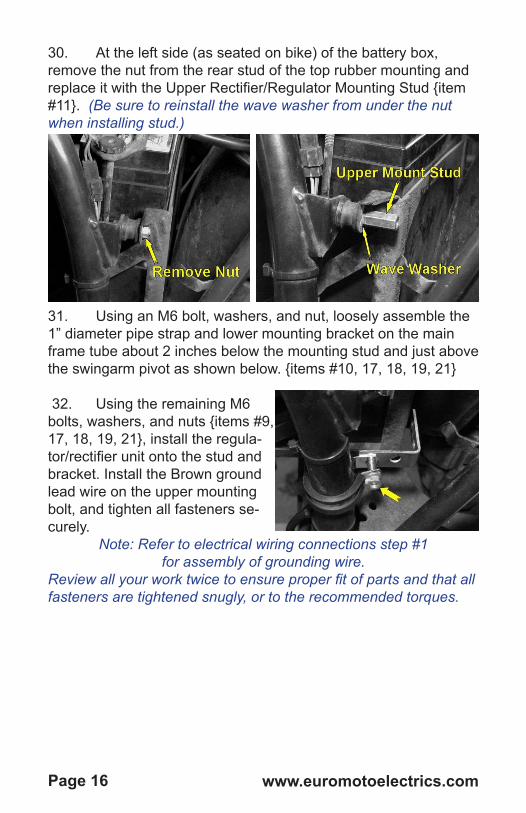
30. At the left side (as seated on bike) of the battery box, remove the nut from the rear stud of the top rubber mounting and replace it with the Upper Rectifier/Regulator Mounting Stud {item #11}. (Be sure to reinstall the wave washer from under the nut when installing stud.)
31. Using an M6 bolt, washers, and nut, loosely assemble the 1” diameter pipe strap and lower mounting bracket on the main frame tube about 2 inches below the mounting stud and just above the swingarm pivot as shown below. {items #10, 17, 18, 19, 21}
32. Using the remaining M6 bolts, washers, and nuts {items #9, 17, 18, 19, 21}, install the regula-tor/rectifier unit onto the stud and bracket. Install the Brown ground lead wire on the upper mounting bolt, and tighten all fasteners se-curely.
Note: Refer to electrical wiring connections step #1for assembly of grounding wire.
Review all your work twice to ensure proper fit of parts and that all fasteners are tightened snugly, or to the recommended torques.

Page 18 www.euromotoelectrics.com
Electrical Installation of Charging System:Recommended good working practices when installing wiring:• Do not reuse old wires or connectors when assembling
wiring harnesses. The pennies saved will cost you time and frustration down the road with poor connections and hard-to-trace symptoms.
• Size wire gauge properly based on the current load that will be carried by that wire. When in doubt, it is always better to go up to a heavier gauge wire.
• Use cable sheathing over wires in areas subject to motion or abrasion to protect the insulation from being worn through.
• Route wires to avoid pinching and moving parts.• Ensure that there is enough wire length to prevent ten-
sion at connections.• For crimped connections, be sure to use a quality
crimping tool that properly stakes the wires into the connector. Dielectric grease should be used in crimped connections.
• When possible we recommend that you solder all per-manent connections.
• Use dielectric silicone grease (included item # 15) for both crimped and removable connections. This resists corrosion in the connections, assisting in maintaining better long-term conductivity in the wiring. Coat wires with dielectric grease before inserting into connectors to be crimped, and fill female half of all quick-connect plugs and connectors.
• Use heat-shrink tubing on connections to seal against moisture and prevent shorts. Do not use electrical tape because the adhesive eventually fails and can expose the connection.
• The use of LI IR and Dry Cell batteries are not reccomended or supported for warranty. Due to the higher internal plate resistance damage to the regulator/rectifier may occur. AGM wet acid batteries are reccomended and original equipment on your motorcycle.
Page [email protected]
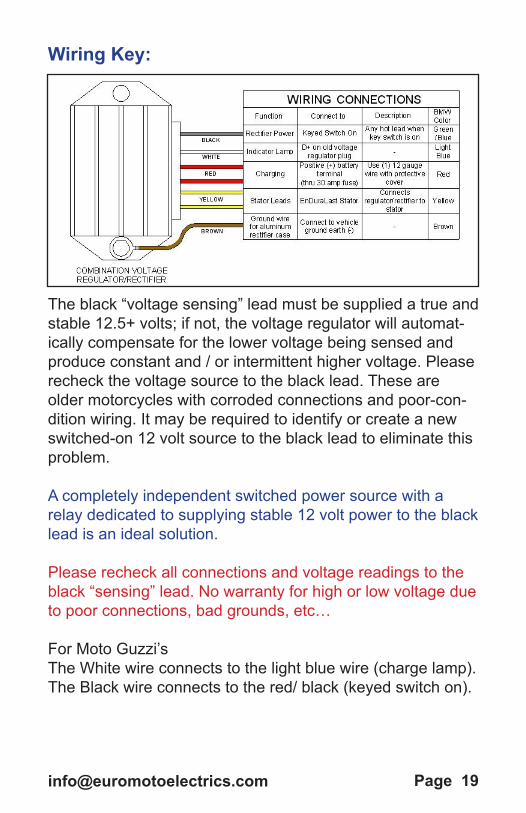
Wiring Key:
The black “voltage sensing” lead must be supplied a true and stable 12.5+ volts; if not, the voltage regulator will automat-ically compensate for the lower voltage being sensed and produce constant and / or intermittent higher voltage. Please recheck the voltage source to the black lead. These are older motorcycles with corroded connections and poor-con-dition wiring. It may be required to identify or create a new switched-on 12 volt source to the black lead to eliminate this problem.
A completely independent switched power source with a relay dedicated to supplying stable 12 volt power to the black lead is an ideal solution.
Please recheck all connections and voltage readings to the black “sensing” lead. No warranty for high or low voltage due to poor connections, bad grounds, etc…
For Moto Guzzi’sThe White wire connects to the light blue wire (charge lamp).The Black wire connects to the red/ black (keyed switch on).
Page 20 www.euromotoelectrics.com
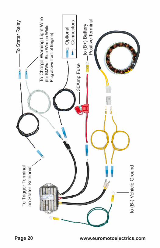
to (B
-) V
ehic
le G
roun
d
30A
mp
Fuse
Opt
iona
l C
onne
ctor
s
To T
rigge
r Ter
min
al
on S
tate
r Sol
enoi
d
To S
tate
r Rel
ay
To C
harg
e W
arni
ng L
ight
Wire
(for B
MW
s - B
lue
Wire
on
Whi
te
Plu
g ab
ove
front
of E
ngin
e)
to (B
+) B
atte
ryP
ositi
ve T
erm
inal

Page [email protected]
Com
bina
tion
Volta
ge R
egul
ator
/ R
ectifi
er W
ire
Col
or
# of
w
ires
Con
nect
or
Col
or C
ode
Func
tion
Con
nect
to o
n M
otor
cycl
eD
esig
natio
n /
Des
crip
tion
BM
W
Col
or
Bla
ck1
Blu
e C
rimp
Fit b
arre
lR
ec/R
eg c
ontro
l P
ower
Key
sw
itche
d po
wer
Any
hot
lead
w
hen
key
switc
h is
on
Gre
en /
blue
Whi
te1
Blu
e C
rimp
Fit b
arre
lC
harg
e W
arni
ng
Lam
p
D +
on
old
volt-
age
regu
lato
r pl
ug
Cha
rge
Indi
cato
r Li
ght
Ligh
t bl
ue
Red
1
Blu
e C
rimp
Fit b
arre
l /
Yello
w R
ing
Term
inal
D/C
Cha
rgin
g C
urre
nt
Bat
tery
Pos
itive
P
ost (
B +
)(thr
u 30
am
p fu
se)
Use
(1) 1
2 ga
uge
wire
with
pr
otec
tive
cove
rR
ed
Yello
w2
Blu
e C
rimp
Fit b
arre
lA
/C p
ower
to
Rec
/Reg
Sta
tor
Use
(2) 1
2 ga
uge
Wire
sN
/A
Gre
en1
Yello
w R
ing
Term
inal
s
Gro
und
for
alum
inum
rect
ifier
cas
e
Bat
tery
neg
ativ
e te
rmin
al (B
-) o
r ve
hicl
e fra
me
/ eng
ine
bolt
Bro
wn

Page 22 www.euromotoelectrics.com
Electrical wiring connections:1) The case of the Rectifier/Regulator unit must be well grounded to function properly. Use two ring terminals {item # 29},to connect the green ground wire lead {item # 35} to one of the mounting bolts of the rectifier/regulator unit and a good solid vehicle ground and/or battery. Possible vehicle ground locations include: The battery’s Negative terminal, a coil mounting bracket screw, another welded frame tab, or a solid non-painted engine or transmission bolt. Route the wire to avoid strain and chafing.
2) The two yellow wires from the rectifier/regulator unit need to be connected to the matching yellow wires from the alternator stator. Use the two yellow 12GA wires {items #34} crimp and heat shrink two blue female barrel connectors {item #25} to one end of each of the yellow wires. Attach to the regulator/rectifier yellow wires and route the wires to avoid pinching or chafing. Cut to length as needed to avoid excessive runs of wiring. Connect the molded white female plug to the other end of the yellow wires. NOTE: The wires from the stator have no sequence and can be attached to either side of the molded white plug {item # 31}. Apply the dielectric silicone grease inside the connectors when making final connections.
3) The two red wires from the rectifier/regulator combine to a single barrel connection. Crimp and heat shrink a blue barrel connector {item # 25} to the in-line fuse holder {item #38}. Attach a yellow ring terminal {item #29} to the other

Page [email protected]
end of the fuse holder and connect to the positive (B+) termi-nal of the battery. Insert a 30 amp blade fuse into the holder.IMPORTANT:
The positive charging current is fused to protect the charging system. Install the enclosed in-line 30 amp fuse holder between the rectifier/regulator and the battery. Route the wires to the battery, using protec-tive sheathing {item #22} to protect from chafing.Note: If the rectifier/regulator unit was mounted in a different location than shown in these instructions, use the red 12-gauge wire {item # 36} and a pair of blue wire connectors {item # 25&26} to reach the battery. Keep the positive red wire run as short as possible for DC efficiency.
4) Cut to length the black wire {item # 32} to extend the black rectifier/regulator wire and connect it to a key-switched hot (positive) wire from the motorcycle’s wiring harness.
• For BMW motorcycles, any wire that is GREEN with a BLUE stripe is powered when the key is switched on.
• The surest place to find switched power on 1970-1984 BMW’s is at terminal #15 (fused terminal) on the terminal board inside the headlamp. This connection is clean and well protected.
• On most models the ignition coils are located conveniently and have a switched pow-er terminal. On BMW dual coil models there is even an
This black wire is the voltage sensing lead and must accurately and consistently sense healthy battery voltage of 12.5+ volts. If this black wire senses low battery voltage the regulator/rectifier can overheat and be damaged.

Page 24 www.euromotoelectrics.com
extra male blade terminal on the coil where the green w/blue wire connects. You can connect to this using a female blade connector {item # 27}.
• For single coil models this wire may be tapped into. If needed, a “piggyback” connector {item # 30} can be used to avoid cutting into the existing wiring harness.
5) Connect the white wire from the rectifier/regulator to the charge warning lamp circuit on the motorcycle. On BMW motorcycles, this is the blue wire in the white two-conductor plug left empty earlier during removal of the original charging system wiring. Connect the ¼” male blade connector {item # 28} to the white wire {item # 33} and insert it into the white plug in the correct location. (use additional heat-shrink tub-ing on the connector if needed to ensure that no conductive areas are exposed outside of the plug, which could cause a short) This white wire is then routed and attached to the white wire on the rectifier/regulator using one of the BLUE barrel connectors {item # 25}.
6) For BMW models: cut and use a section of the black wire {item #32} and one each of the male and female blade connectors {items #27 & 28} to reconnect the starter relay to the starter solenoid trigger terminal. This connection was lost

Page [email protected]
when the original wiring harness was disconnected at the white plug above the engine. • Connect the male end of the wire into the black wire ter-
minal of the white plug. (Use additional heat-shrink tubing on the blade connector if needed to ensure no conductive area is exposed beyond the plug to prevent the chance of a short.)
• Connect the female connector to the starter solenoid trig-ger terminal. It is a male connector on the starter solenoid near the large bolt at the front. It might be hard to see.
• Route the wire through the grommet at the top of the engine to prevent it from being pinched or chaffed and grounding out.
• Secure the white plug and the two wires just attached to it with wire ties so that they will not pull or fall out during operation.
7) Use tie wraps to hold any loose wires in place and to prevent rubbing from vibrations. Ensure that wires do not chafe against sharp objects or make extreme bends.
8) Review the above and inspect work. Twice. Maybe three times.• Ensure that all wiring is connected to the proper loca-
tions! Check the wire colors.• Check that all connections are clean and snug.• Check wire routing to ensure that wires are not pinched,
have no sharp bends, and are not in danger of chafing.

Page 26 www.euromotoelectrics.com
• Ensure that any remaining unused electrical wiring and connectors from the original charging system are properly secured out of the way and insulated against shorting.
Electrical installation is now complete!
IMPORTANT: The vehicle must have a good, fully charged battery for the electrical system to operate properly !• Using a digital voltmeter, the voltage reading MUST be
12.43 Volts or higher,• If your battery is over 3 years old, it should be replaced.• If your battery has been discharged 3 times or more, it is
sulfated and MUST be replaced ! A sulfate damaged battery will not;
1. accept a charge and may damage your charging system.
2. provide sufficient voltage and / or current to turn the starter motor.
• Make sure the positive and negative cables are free of corrosion, and have clean tight fit.
Battery Voltage State of Charge / Battery Condition
Recommended Action
12.7 V 100 % Battery Good12.6 V 90% Battery Good12.4 V 75 % Charge Battery12.2 V 50 % Replace Battery12.0 V 25 % Replace Battery
11.9 V or less Discharged Replace BatteryDue to older battery high internal battery resistance the charging system has to work harder. While good batteries absorb voltage spikes, older and/or defective batteries may produce voltage spikes that can cause damage to the voltage regulator and / or rectifier, etc. This would create a high voltage and / or low voltage output and may cause the charging system to ultimately fail. The use of LI IR and Dry Cell batteries are not supported for warranty. Due to the higher internal plate resistance damage to the regula-tor/rectifier may occur.

Page 28 www.euromotoelectrics.com
Testing of your new Charging System:1. Review all work done during the installation process.
Ensure that all components are mounted correctly and securely. Check all wiring to make sure that the com-ponents are interconnected properly and that wires are routed to avoid pinching, binding, and rubbing.
2. With the ignition switch still off and transmission in gear (release the brake), have an assistant turn rear wheel while you watch the rotor to ensure that it runs true and straight in the stator without touching.
3. If needed, temporarily reinstall the fuel tank or provide an alternate temporary fuel supply to the engine.
4. After confirming all work, reconnect battery.NOTE: It is highly recommended that both the positive and negative battery terminals and wire connections
be thoroughly cleaned and coated with dielectric grease to ensure good conductivity
5. Start the motorcycle engine and visually check that the rotor runs true in the stator ring without contact.
CAUTION! Stop the engine immediately if there is any rubbing/contact between the rotor and stator!
6. While the engine is running, connect the voltmeter across the battery terminals to check for charging voltage.
7. Watch for 14.2 volts at the battery over a range of engine speeds and electrical loads. Stable 14.2 volts should be maintained with all electrical loads turned on at once.
8. If a DC ammeter capable of reading at least 40 amps is available, shut down engine and connect ammeter into charging wire from regulator/rectifier. Restart engine and check for charging current under various engine speeds and electrical loads.
9. After confirming correct operation of your new charging system, turn off the engine and remove the fuel tank or temporary fuel supply from motorcycle to allow the rest of the engine / motorcycle to be reassembled properly.

Page [email protected]
Trouble Shooting - Intermittent, Low, or High VoltageThe Voltage Regulator / Rectifier was computer
tested at the factory to ISO standards.A) If the voltage regulator is showing intermittent or unstable voltage production the problem is with the soldering process or connector. Re-solder or use a suitable connector for an improved connection.
B) If there is continuous high voltage (over 15 volts) the problem is the not perfect contact in black cable with the igni-tion-on “hot” lead, or a faulty ground. If in these connections there is a loss of voltage, the regulator automatically increas-es the recharging voltage.
C) The black “voltage sensing” lead must be supplied a true and stable 12.5+ volts; if not, the voltage regula-tor will automatically compensate for the lower voltage being sensed and produce constant and / or intermittent higher voltage. Please recheck the voltage source to the black lead. These are older motorcycles with cor-roded connections and poor-condition wiring. It may be required to identify or create a new switched-on 12 volt source to the black lead to eliminate this problem.A completely independent switched power source with a relay dedicated to supplying stable 12 volt power to the black lead is an ideal solution. Please recheck all connections and voltage readings to the black “sensing” lead. No warranty for high or low voltage due to poor connections, bad grounds, etc…
Important Notes:Do not overload the system! Although you will have dra-matically increased your wattage & amperage output, you must still observe the laws of physics and electromagnetism. Please review the wattage demands of all additional acces-sories before installation and use. To increase the reliability of the charging system, there should be a 10-20% buffer

Page 30 www.euromotoelectrics.com
margin between demand and output capacity at your engine operating speed. (Refer to the charge system output chart on page 2)• Total wattage demand should NEVER exceed the
wattage capacity of the system.
Final Reassembly:NOTES:• To ensure ease of future service, we highly recom-
mend that all fasteners be thoroughly cleaned and that a good quality anti-seize paste be used during reassembly of parts.
• With the EnDuraLast charging system installed there is no longer any risk of shorting out electrical compo-nents when removing/installing the engine front cover. Therefore you no longer need to worry about discon-necting the battery before working with the front cover.
• Replace engine front cover and secure the cover bolts; Some early models may require modification of the right lower reinforcing cast rib & lug to allow clearance of the lower stator bolt. NOTE: Make sure that no wires are pinched or restricted where they exit through the grommets at the top of the engine when the front & top engine covers are installed.
1. Replace engine top cover and secure the cover bolts. 2. Reinstall air cleaner element and housing.3. Replace fuel tank, ensuring that it is properly seated in
mounting locations and all fuel & vent tubes are recon-nected properly.
4. Reinstall the oil cooler if so equipped.5. Reinstall any fairing or engine protection bars removed
during disassembly.6. Replace battery side covers and reattach left side lift
handle.7. If removed earlier, reinstall the seat.8. Before restarting the engine, move the steering through

Page [email protected]
its complete range to check for binding or pinching of ca-bles or wires. Roll the throttle open and closed, watching each carburetor to ensure proper operation, and feel for any binding in the throttle.
9. Restart engine and check again for proper charging.10. Suit up and Ride !!!
Credits & Thanks:Euro MotoElectrics wishes to thank all the members of the Airheads BMW club www.airheads.org for their input and assistance in the devel-opment of this kit.
In addition, thanks go out to Karl Kugler of www.EvolutionCycles.com for his work providing the photos and text of these installation instructions, and Scott Lydiard for his fine-tuning edits.
Installation Notes:

Page 32 www.euromotoelectrics.com
Battery agein Months months
Battery voltageat rest volts
Battery voltagewith Ignition key ON volts
Voltage at BLACK wire to Regulator/Rectifier volts
Prior to calling for technical assistance, please identify the following so we can bet-ter assist you:
Typical Voltage Regulator/Rectifier install locations: