ENCE717 – Bridge Engineering Concrete Bridges Reinforced...
10
1 ENCE717 – Bridge Engineering Reinforced and Prestressed Concrete Bridges Chung C. Fu, Ph.D., P.E. (http: www.best.umd.edu) Concrete Bridges 1. Reinforced Concrete (RC) Bridges (4.0) 2. Prestressed Concrete (PC) Bridges (5.0) i. Precast Pre-tensioned Concrete Bridges ii. Precast/Cast-in-place post-tensioned Concrete Bridge iii. PC Bridge Modeling iv. PC Bridge Load Rating 3. Curved Concrete Bridges (6.0) Portland Cement Types in Bridges The AASHTO Specification M85 lists ten types of portland cement : 1. Type I Normal 2. Type IA Normal, air-entraining 3. Type II Moderate sulfate resistance 4. Type IIA Moderate sulfate resistance, air-entraining 5. Type II(MH) Moderate heat of hydration, moderate sulfate resistance 6. Type II(MH)A Moderate heat of hydration, moderate sulfate resistance, air-entraining 7. Type III High early strength 8. Type IIIA High early strength, air-entraining 9. Type IV Low heat of hydration 10. Type V High sulfate resistance High-Performance Concrete in Bridges • High-Strength Concrete – in excess of 8.0 ksi specified at 56 days to achieve longer span lengths, wider beam spacing, or the use of shallower sections. • Low-Permeability Concrete - beneficial in reducing the rate of penetration of chlorides into the concrete; most high-strength concretes have a low permeability but not all low permeability concretes have high strength. • Self-Consolidating Concrete (SCC) - a highly flowable, nonsegragating concrete that can spread into place, fill the formwork, and encapsulate the reinforcement without any mechanical consolidation; using a high- rangewater-reducing admixture, and, in some cases, including a viscosity-modifying admixture; more expensive due to more stringent quality control • Ultra-High-Performance Concrete (UHPC) - compressive strength greater than 21.7 ksi; a cementitious composite material that contains cement, fine sand, silica fume, ground quartz, superplasticizer, steel or plastic fibers, and water
Transcript of ENCE717 – Bridge Engineering Concrete Bridges Reinforced...
1
ENCE717 – Bridge EngineeringReinforced and Prestressed
Concrete Bridges
Chung C. Fu, Ph.D., P.E.(http: www.best.umd.edu)
Concrete Bridges1. Reinforced Concrete (RC) Bridges (4.0)
2. Prestressed Concrete (PC) Bridges (5.0)
i. Precast Pre-tensioned Concrete Bridges
ii. Precast/Cast-in-place post-tensioned Concrete Bridge
iii. PC Bridge Modeling
iv. PC Bridge Load Rating
3. Curved Concrete Bridges (6.0)
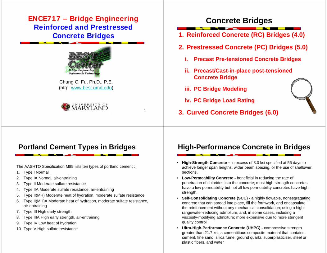
Portland Cement Types in Bridges
The AASHTO Specification M85 lists ten types of portland cement :1. Type I Normal2. Type IA Normal, air-entraining3. Type II Moderate sulfate resistance4. Type IIA Moderate sulfate resistance, air-entraining5. Type II(MH) Moderate heat of hydration, moderate sulfate resistance6. Type II(MH)A Moderate heat of hydration, moderate sulfate resistance,
air-entraining7. Type III High early strength8. Type IIIA High early strength, air-entraining9. Type IV Low heat of hydration10. Type V High sulfate resistance
High-Performance Concrete in Bridges
• High-Strength Concrete – in excess of 8.0 ksi specified at 56 days to achieve longer span lengths, wider beam spacing, or the use of shallower sections.
• Low-Permeability Concrete - beneficial in reducing the rate of penetration of chlorides into the concrete; most high-strength concretes have a low permeability but not all low permeability concretes have high strength.
• Self-Consolidating Concrete (SCC) - a highly flowable, nonsegragatingconcrete that can spread into place, fill the formwork, and encapsulate the reinforcement without any mechanical consolidation; using a high-rangewater-reducing admixture, and, in some cases, including a viscosity-modifying admixture; more expensive due to more stringent quality control
• Ultra-High-Performance Concrete (UHPC) - compressive strength greater than 21.7 ksi; a cementitious composite material that contains cement, fine sand, silica fume, ground quartz, superplasticizer, steel or plastic fibers, and water

UHPC applications to footbridges and roadbridges
110’
32’-52’-30’
400’
UHPC Application
The first UHPC bridge constructed in the United States. The bridge includes three UHPC prestressed I-girders spanning a creek in rural Iowa.
curing at ambient temperatures, or steam curing up to 115ºF (46ºC), until the compressive strength of match-cured cylinders attained 14,500 psi (100 MPa).thermal treatment of approximately 190ºF (88ºC) along with relative humidity of at least 95% for at least 48 hours [5400 psi (37 MPa) at 28 hours, 14,900 psi (103 MPa) at 50 hours, and 32,400 psi (223 MPa) after the second stage curing./
养护
Concrete and Steel Material Properties
• Stress-strain relation for monotonic loading of confined and unconfined concrete based on Mander, et al. model
• True and Idealized steel stress-strain relationships
• Stress-strain response of SFRC
• FRP uniaxial stress-strain curve for carbon and glass FRP composites in the fiber direction
Behavior of Non-skewed/Skewed Concrete Beam-Slab Bridges

Principle and Modeling of Concrete Beam-Slab Bridges
• Linear elastic modeling – production purposes It can be simplified as a beam or a grid The equivalent stiffness can be calculated from equation 2.6 for rectangular void
block or equation 2.7 for circular block. The most common types of finite element used are flat shell elements A beam-and-slab or cellular bridge deck may require a three-dimensional (3D)
finite element analysis.• Nonlinear modeling – research/study purposes
as an equivalent uniaxial material which is distributing throughout the finite element. It is often referred as “smeared” steel (smeared model);
as discrete bars connected to the nodes in the finite element model (discrete model);
as a uniaxial element which is embedded in a larger finite element (embedded model).
• FRC/FRP modeling – research/study purposes The FE model uses a smeared cracking approach for the concrete and three-
dimensional layered elements to model FRP composites
Prestressing steel, Strand Anchors and Couplers
Ref: “PCI Bridge Design Manual”
Pretensioning Method –Prestress loading stages
Tensile Stress Release of Precast Prestressed Concrete Girders
Prestressing strand profiles (a) harped strands (b) debonded strands (the dashed lines indicate debonding material around prestressing strand)

Precast Prestressed Concrete Girders
(a) Mid section (b) End section
Figure 5.35 - Section of the AASHTO beams with strands
Precast Prestressed Concrete Girders
Nonprestressed Reinforcement Configurations for Precast Prestressed Concrete Girders
Box Beam I- & Bulb-Tee Beam
Deck Bulb-TeeRef: “PCI Bridge Design Manual”
Precast Prestressed Concrete Girders
Figure 5.35 - Section of the AASHTO beams with strands

Post-tensioning Strand Anchors & Couplers
Ref: “PCI Bridge Design Manual”
Post-tensioning Method
• Figure 5.4 illustrates a post-tensioned beam before concrete pouring and post-tensioning to show its rebar cages and conduits.
• Figure 5.5 shows a perspective of a typical precast balanced cantilever segment with the various types of tendons
Post-tensioning Method –Typical Layout
• Figure 5.6 – Cantilever Post-Tensioning Tendons Anchored on the Segment Faces
• Figure 5.7 – Interior Span Post-Tensioning for Span-By-Span Construction
Principle and Modeling of Prestressing
The four most critical conditions in the structural modeling of tendons are:• Immediate loss of stress in tendon - Friction between the
strand and its sheathing or duct causes two effects: (1) curvature friction, and (2) wobble friction.
• Elastic shortening of the concrete • Long-term losses - (1) relaxation of the prestressing steel, (2)
shrinkage in concrete, and (3) creep in concrete. • Change in stress due to bending of the member under
applied loading Pretensioning/Post-tensioning tendon modeling• Tendon modeled as applied loading• Tendon modeled as load resisting elements
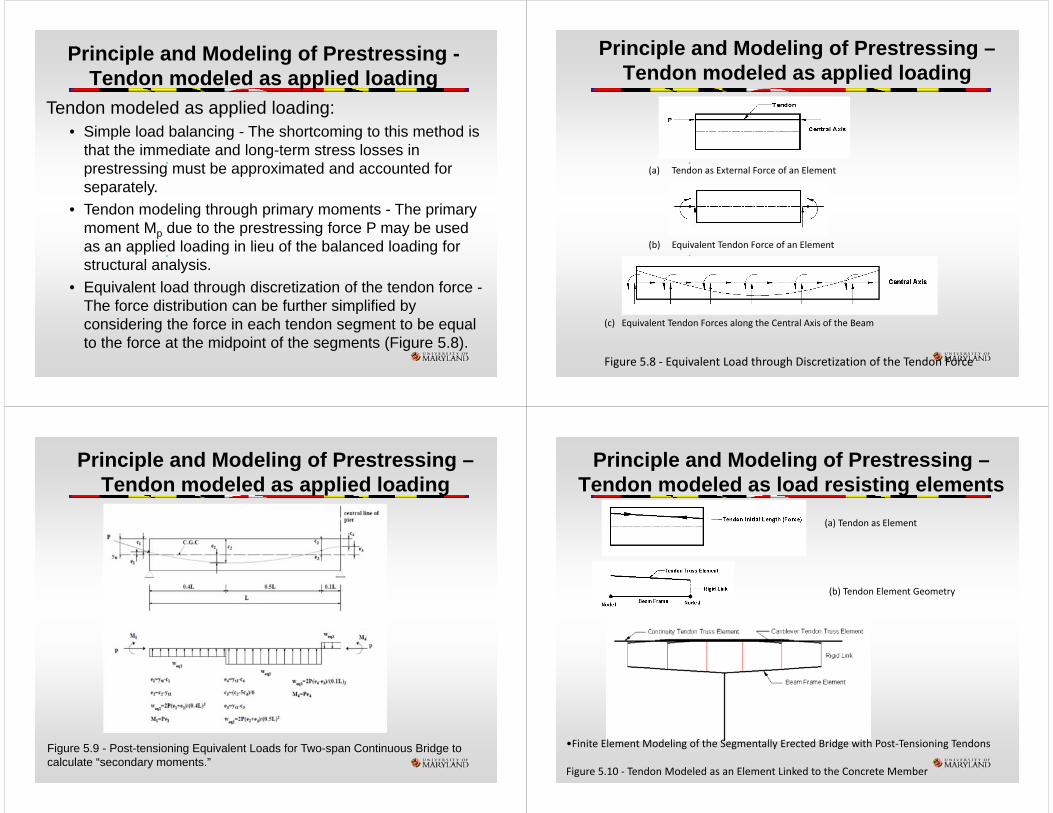
Principle and Modeling of Prestressing -Tendon modeled as applied loading
Tendon modeled as applied loading:• Simple load balancing - The shortcoming to this method is
that the immediate and long-term stress losses in prestressing must be approximated and accounted for separately.
• Tendon modeling through primary moments - The primary moment Mp due to the prestressing force P may be used as an applied loading in lieu of the balanced loading for structural analysis.
• Equivalent load through discretization of the tendon force -The force distribution can be further simplified by considering the force in each tendon segment to be equal to the force at the midpoint of the segments (Figure 5.8).
Principle and Modeling of Prestressing –Tendon modeled as applied loading
(a) Tendon as External Force of an Element
(b) Equivalent Tendon Force of an Element
(c) Equivalent Tendon Forces along the Central Axis of the Beam
Figure 5.8 ‐ Equivalent Load through Discretization of the Tendon Force
Principle and Modeling of Prestressing –Tendon modeled as applied loading
Figure 5.9 - Post-tensioning Equivalent Loads for Two-span Continuous Bridge to calculate “secondary moments.”
Principle and Modeling of Prestressing –Tendon modeled as load resisting elements
(a) Tendon as Element
(b) Tendon Element Geometry
•Finite Element Modeling of the Segmentally Erected Bridge with Post‐Tensioning Tendons
Figure 5.10 ‐ Tendon Modeled as an Element Linked to the Concrete Member
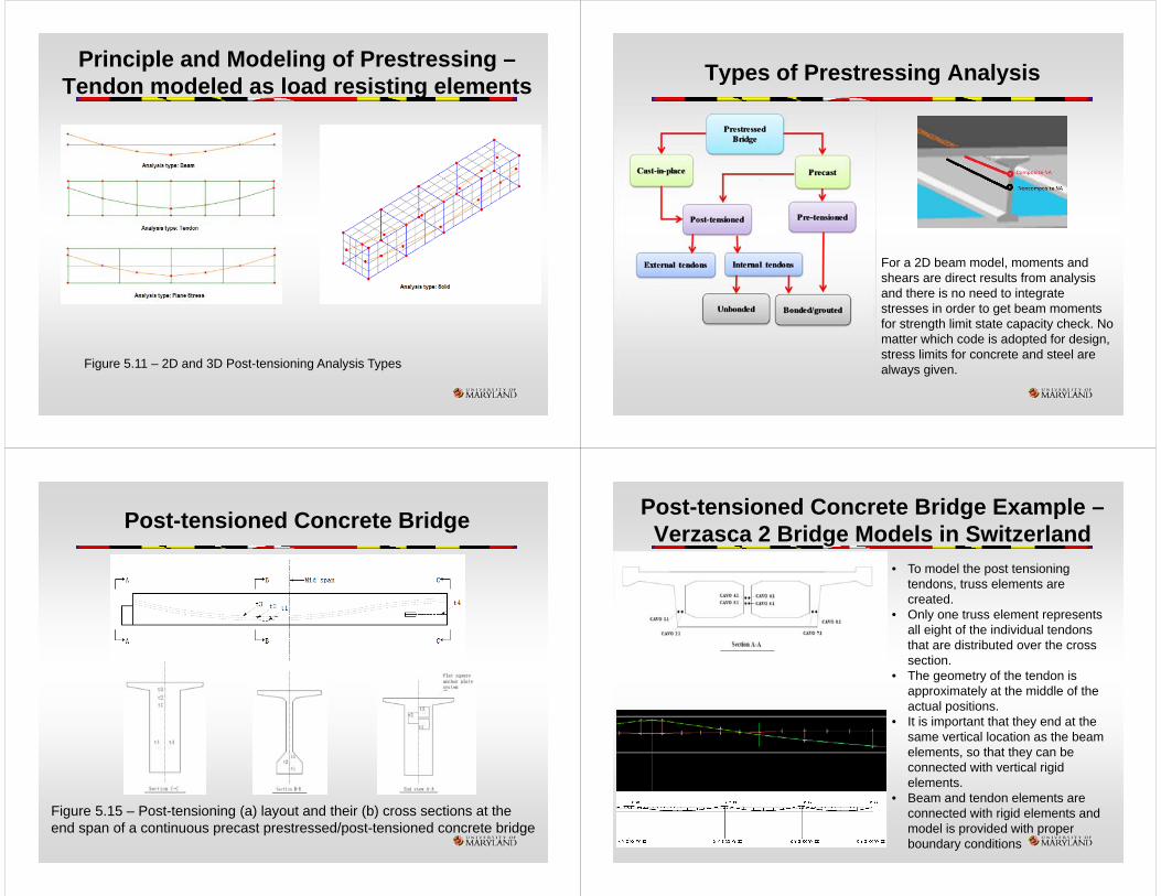
Principle and Modeling of Prestressing –Tendon modeled as load resisting elements
Figure 5.11 – 2D and 3D Post-tensioning Analysis Types
Types of Prestressing Analysis
For a 2D beam model, moments and shears are direct results from analysis and there is no need to integrate stresses in order to get beam moments for strength limit state capacity check. No matter which code is adopted for design, stress limits for concrete and steel are always given.
Post-tensioned Concrete Bridge
Figure 5.15 – Post-tensioning (a) layout and their (b) cross sections at the end span of a continuous precast prestressed/post-tensioned concrete bridge
Post-tensioned Concrete Bridge Example –Verzasca 2 Bridge Models in Switzerland
• To model the post tensioning tendons, truss elements are created.
• Only one truss element represents all eight of the individual tendons that are distributed over the cross section.
• The geometry of the tendon is approximately at the middle of the actual positions.
• It is important that they end at the same vertical location as the beam elements, so that they can be connected with vertical rigid elements.
• Beam and tendon elements are connected with rigid elements and model is provided with proper boundary conditions

Segmental Post-tensioned Concrete Bridge
Figure 5.38 - Bridge Elevation Profile, Bottom Slab Thickness Variation and Segment Division
Figures 5.40 & 5.41 – Top flange stresses before and after closure
Post-tensioned Concrete Bridge Example –Sutong Bridge approach spans in China
1640/2 1640/2
18 18
375
375
100
45
170
32
32
1500
450
Section at midspan Section at piers
• The continuous rigid frame of Sutong Bridge approach spans is a segmental, cast-in-place concrete cantilever bridge completed in 2007
• The span distribution is 140m+268m+140m (460’+880’+460’), among the longest spans in the world
Figure 5.44 ‐ Conventional layout of longitudinal tendons
Figure 5.45 ‐ Straight layout of longitudinal tendons (end of 1980s)
Figure 5.46 ‐ Current layout of longitudinal tendons with the webs’ bent‐down tendons (early 2000s)
Post-tensioned Concrete Bridge Example –Sutong Bridge approach spans in China
T1 T31
F1
F27 F31
Z1Z15
T1T31
F1
F27F31Cantilever tendons in top slabs
Cantilever tendons in webs Closure tendons in central spanPiers
T32 T33
B1~4,B6 B1B7B7B5
Closure tendons in side span
Figure 5.49 ‐ Segments and layout of
Figure 5.50 ‐ Layout of the preparatory external tendons
Post-tensioned Concrete Bridge Example –Sutong Bridge approach spans in China
Figure 5.52 - Increment of deflections of the bridge after completion with the pre-setting internal tendons
Figure 5.53 - Increment of deformations of the bridge after completion without the pre-setting internal tendons
0 100 200 300 400 500
-250
-200
-150
-100
-50
0
50
Def
orm
atio
n (m
m)
Distance from the left support of side span(m)
One year after completion Tensioning pre-setting tondons Two years after completion Three years after completion Ten years after completion thirty years after completion
0 100 200 300 400 500
-250
-200
-150
-100
-50
0
50
Def
orm
atio
n (m
m)
Distance from the left support of side span(m)
One year after completion Two years after completion Three years after completion Ten years after completion Thirty years after completion

PC Bridge LRFR Rating Equation
33
PC Bridge LRFR Rating Equation• LFR moment
34
Inventory rating Operating rating
• LRFR moment
Inventory rating Operating rating
• LRFR shearWhere, , , and are the shear resistance components due to the concrete, shear reinforcement, and the inclined prestressing strand, respectively.
PC Bridge LRFR Rating Equation
35
Service III Load Rating
Service I Load RatingCase I: The stress at the top of girder under 0.5 (permanent + transient loads)
Case II: The stress at the top of girder under permanent + transient loads
Case III: The stress at the top of slab under 0.5 (permanent + transient loads)
Case IV: The stress at the top of slab under permanent + transient loads
PC Bridge LFR and LRFR Comparison
36
Ref: “PCI Bridge Design Manual”

Curved Concrete Bridges
Figure 6.2 – Hollow box subjected to torsion
Figure 6.3 - Shear stresses in multi-cell section
Principle and Modeling of Curved Concrete Bridges
(a) Typical spine beam model
(b) Typical grillage model
3D FEM model of example 3
Linn Cove Viaduct, NC
Principle and Modeling of Curved Concrete Bridges
(a) Bearing supported connection
(b) Monolithic connection
Figure 6.6 – Super‐ and sub‐structure connection
Principle and Modeling of Curved Concrete Bridges
Figure 6.8 – Grillage modeling of a longitudinal box cross section
Figure 6.7 – Box sectional property calculation