EnaSolar GT Series Solar Inverter Manual v2.3 Page 1
28
EnaSolar GT Series Solar Inverter Manual v2.3 Page 1
Transcript of EnaSolar GT Series Solar Inverter Manual v2.3 Page 1
EnaSolar GT Series Solar Inverter Manual v2.3 Page 1

EnaSolar GT Series Solar Inverter Manual v2.3 Page 2
About EnaSolar EnaSolar is a division of Enatel Limited, based in Christchurch, New Zealand. EnaSolar designs, manufactures and distributes efficient, cost effective, sustainable and upgradeable solar inverters to the global market.
EnaSolar and the EnaSolar ‘e’ are both registered trademarks. Copyright © 2012 EnaSolar. No part of this document may be reproduced in any form or disclosed to third parties without the express written consent of EnaSolar Limited, 66 Treffers Road, Christchurch 8042, New Zealand.
EnaSolar reserves the right to revise this document and to periodically make changes to the content without obligation to give prior notification of such changes, unless required to do so by prior arrangement.
Exclusion for Documentation Unless specifically agreed to in writing, EnaSolar makes no warranty as to the accuracy, sufficiency, or suitability of any technical or other information provided in its manuals or other documentation.
EnaSolar assumes no responsibility or liability for losses, damages, costs or expenses, whether special, direct, indirect, consequential or incidental, which might arise out of the use of such information. The use of any such information will be entirely at the user’s risk.
Manual Version DN120166D EnaSolar GT Series Solar Inverter Manual - MAN-ESENG-v2.3
Applicable for Products 1.5KWGT-AUNZ-UK(E) 2KWGT-AUNZ-UK(E) 3KWGT-AUNZ-UK(E) 3.8KWGT-AUNZ-UK(E) 4KWGT-AUNZ-UK(E) 5KWGT-AUNZ-UK(E) 5KWGT-AU4.6(E) Installation Details The following table must be filled in by the installer:
Installer’s Company:
Installer’s Name:
Installer’s Tel/Email:
Inverter Model:
Inverter Serial Number:
Installation Date:
Panel Manufacturer:
Panel Model:
Panel Configuration: No. of strings: No. of panels per string:
EnaSolar GT Series Solar Inverter Manual v2.3 Page 3
Contents
1. ABOUT THIS MANUAL ............................................................................................................. 4Purpose and Audience .............................................................................................................. 4Safety Instructions .................................................................................................................... 4 Important Notice to the Installer ................................................................................................ 4 Warranty Information ................................................................................................................ 4
2. INTRODUCTION ........................................................................................................................ 5About the Inverter ..................................................................................................................... 5
3. INSTALLATION .......................................................................................................................... 5Mechanical Specifications ......................................................................................................... 5Installation Options ................................................................................................................... 5Location Requirements ............................................................................................................. 7Installing the Wall Mount ........................................................................................................... 8
4. WIRING ...................................................................................................................................... 8Wall Mount ................................................................................................................................ 8Earthing of Solar Arrays .......................................................................................................... 10Inverter Module ....................................................................................................................... 12Testing the Voltages ............................................................................................................... 13
5. CONFIGURATION ................................................................................................................... 13Configuration Overview ........................................................................................................... 13Configuration Details ............................................................................................................... 14Inverter Configuration Software .............................................................................................. 15Configuration through the Inverter Web Page ........................................................................ 16Ethernet Connection ............................................................................................................... 17Ad-hoc Wi-Fi Connection ........................................................................................................ 17Default Ad-hoc Wi-Fi Settings: ................................................................................................ 18Infrastructure Wi-Fi Connection .............................................................................................. 18Infrastructure Wi-Fi Setup through a USB Connection ........................................................... 18Infrastructure Wi-Fi Setup through an Ad-hoc Wi-Fi Connection ............................................ 19
6. COMMISSIONING THE SYSTEM ........................................................................................... 20Fitting the Display Module ....................................................................................................... 20Using the Inverter .................................................................................................................... 20Stopping the Inverter ............................................................................................................... 21Maintenance ........................................................................................................................... 21 Warranty Information .............................................................................................................. 21
7. ADVANCED USAGE ................................................................................................................ 21Advanced Settings .................................................................................................................. 22Advanced Settings - Network .................................................................................................. 22Advanced Settings - Grid Connect .......................................................................................... 22Advanced Settings - Other ...................................................................................................... 22
8. TROUBLESHOOTING ............................................................................................................. 23Installer Serviceable Components .......................................................................................... 23General Troubleshooting ........................................................................................................ 24
9. UNDERSTANDING THE PART NUMBER .............................................................................. 2610. GLOSSARY ............................................................................................................................. 2611. TECHNICAL SPECIFICATIONS .............................................................................................. 27
EnaSolar GT Series Solar Inverter Manual v2.3 Page 4
1. ABOUT THIS MANUAL
Purpose and Audience
The purpose of this manual is to explain the procedures for installing and troubleshooting the EnaSolar GT Series Solar Inverter.
The inverter must be installed by suitably qualified solar technician. Please read this manual thoroughly before installing the inverter.
Safety Instruct ions
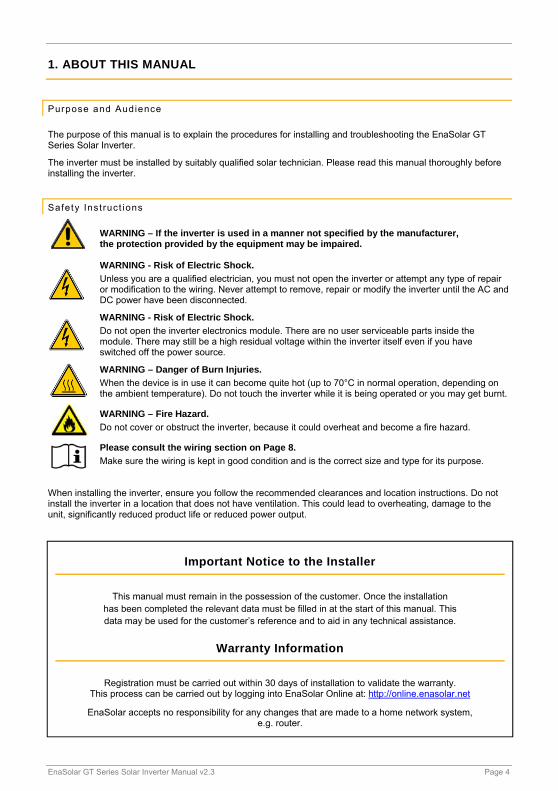
WARNING – If the inverter is used in a manner not specified by the manufacturer, the protection provided by the equipment may be impaired.
WARNING - Risk of Electric Shock.
Unless you are a qualified electrician, you must not open the inverter or attempt any type of repair or modification to the wiring. Never attempt to remove, repair or modify the inverter until the AC and DC power have been disconnected.
WARNING - Risk of Electric Shock.
Do not open the inverter electronics module. There are no user serviceable parts inside the module. There may still be a high residual voltage within the inverter itself even if you have switched off the power source.
WARNING – Danger of Burn Injuries.
When the device is in use it can become quite hot (up to 70°C in normal operation, depending on the ambient temperature). Do not touch the inverter while it is being operated or you may get burnt.
WARNING – Fire Hazard.
Do not cover or obstruct the inverter, because it could overheat and become a fire hazard.
Please consult the wiring section on Page 8.
Make sure the wiring is kept in good condition and is the correct size and type for its purpose.
When installing the inverter, ensure you follow the recommended clearances and location instructions. Do not install the inverter in a location that does not have ventilation. This could lead to overheating, damage to the unit, significantly reduced product life or reduced power output.
Important Notice to the Installer
This manual must remain in the possession of the customer. Once the installation has been completed the relevant data must be filled in at the start of this manual. This data may be used for the customer’s reference and to aid in any technical assistance.
Warranty Information
Registration must be carried out within 30 days of installation to validate the warranty. This process can be carried out by logging into EnaSolar Online at: http://online.enasolar.net
EnaSolar accepts no responsibility for any changes that are made to a home network system, e.g. router.
EnaSolar GT Series Solar Inverter Manual v2.3 Page 5
2. INTRODUCTION
About the Inverter
The EnaSolar GT Series Solar Inverter is designed to convert DC solar power to AC (mains) power, which can be used to power appliances in a home or business.
Inverter Features: Built-in Wi-Fi as standard for web based PV system monitoring & reporting.
Optional Ethernet version available. Integrated lockable AC and DC isolating switches. Wide operating voltage range starting at 120V, allowing you to install with a minimal panel array. 5 year warranty included as standard, upgradeable to 10 years. Front mounted heat sink allows more airflow, easy care and cleaning. A more efficient design means longer product life and less call outs.
3. INSTALLATION
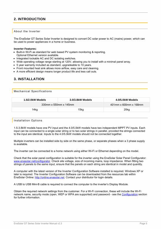
Mechanical Speci f icat ions
1.5/2.0kW Models 3.0/3.8kW Models 4.0/5.0kW Models
330mm x 550mm x 145mm 401mm x 600mm x 168mm
14kg 15kg 20kg
Insta l la t ion Opt ions
1.5-3.8kW models have one PV input and the 4.0/5.0kW models have two independent MPPT PV inputs. Each input can be connected to a single solar string or to two solar strings in parallel, provided the strings connected to the input are identical. Inputs to the 4.0/5.0kW models should not be connected together.
Multiple inverters can be installed side by side on the same phase, or separate phases when a 3 phase supply is available.
The inverter can be connected to a home network using either Wi-Fi or Ethernet depending on the model.
Check that the solar panel configuration is suitable for the inverter using the EnaSolar Solar Panel Configurator: www.enasolar.net/configurator. Check site voltage, size of incoming mains, loop impedance. When fitting two strings of panels to the same input, ensure that the panels on each string are identical in model and quantity.
A computer with the latest version of the Inverter Configuration Software installed is required. Windows XP or later is required. The Inverter Configuration Software can be downloaded from the resources tab within EnaSolar Online: http://online.enasolar.net. Contact your distributor for login details.
A USB to USB Mini-B cable is required to connect the computer to the inverter’s Display Module.
Obtain the required network settings from the customer. For a Wi-Fi connection, these will include the Wi-Fi network name, security mode (open, WEP or WPA are supported) and password - see the Configuration section for further information.
EnaSolar GT Series Solar Inverter Manual v2.3 Page 6
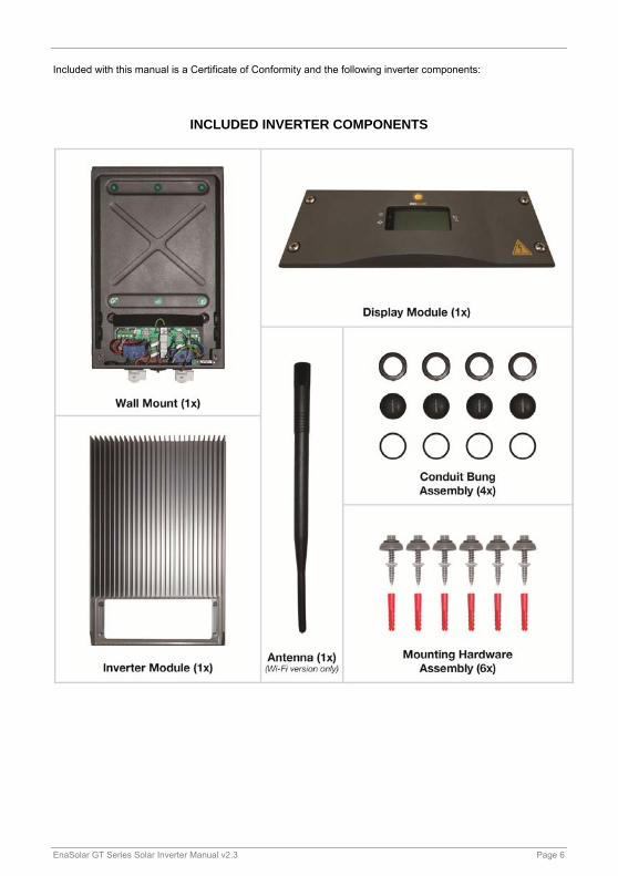
Included with this manual is a Certificate of Conformity and the following inverter components:
INCLUDED INVERTER COMPONENTS
EnaSolar GT Series Solar Inverter Manual v2.3 Page 7
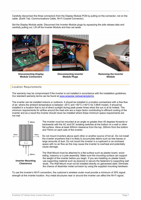
Carefully disconnect the three connectors from the Display Module PCB by pulling on the connector, not on the cable. (Earth Tab, Communications Cable, Wi-Fi Coaxial Connector).
Set the Display Module aside. Disconnect the Inverter Module plugs by squeezing the side release tabs and carefully pulling out. Lift off the Inverter Module and then set aside.
Locat ion Requi rements
The warranty may be compromised if the inverter is not installed in accordance with the installation guidelines. Our standard warranty terms can be found at www.enasolar.net/warrantyterms
The inverter can be installed indoors or outdoors. It should be installed in a location somewhere with a free flow of air, where the ambient temperature is between -25°C and +50°C (+40°C for 3.8kW model). It should be installed in a location that is out of direct sunlight during peak power times when the sun is at its hottest. The minimum requirements for airflow around the heat sink are a major factor contributing to efficient cooling of the inverter and as a result the inverter should never be installed where these minimum space requirements are not met.
The inverter must be mounted at an angle no greater than 45 degrees forwards or backwards with the AC and DC isolating switches at the bottom on a wall or other flat surface. Allow at least 400mm clearance from the top, 300mm from the bottom and 70mm on each side of the inverter.
Do not mount inverters above each other or another source of hot air. Do not install the inverter anywhere that it is likely to accumulate debris such as tree leaves or large amounts of dust. Do not mount the inverter in a cupboard or an enclosed space with no air flow as this may cause the inverter to overheat and potentially cause damage.
The Wall Mount must be attached to a flat surface such as plaster board, wood siding, masonry or a pole assembly. Make sure the mounting surface can support the weight of the inverter before you begin. If you are installing on plaster board, use supporting material such as plywood or secure the fasteners to supporting wall studs. The Wall Mount must not be installed directly on galvanised steel. Eliminate the chance of dissimilar metal corrosion by using the supplied mounting hardware.
To use the inverter’s Wi-Fi connection, the customer’s wireless router must provide a minimum of 30% signal strength at the inverter location. Any metal structures near or around the inverter can affect the Wi-Fi signal.
Disconnecting Display Module Connectors
Disconnecting Inverter Module Plugs
Removing the Inverter Module
Inverter Mounting Clearances
EnaSolar GT Series Solar Inverter Manual v2.3 Page 8
Insta l l ing the Wal l Mount
The Wall Mount comes with six pre-drilled 8mm holes for attaching it to the wall, as well as eight conduit holes for electrical wires.
Mark and drill at least four mounting holes, fit the Wall Mount with the supplied Mounting Hardware, ensuring it is attached securely.
Inspect the installation for any potential water leaks. Seal using an appropriate silicone sealant if required.
Note: If the inverter is incorrectly installed, this will invalidate the warranty. Please see our warranty terms and conditions on our website.
4. WIRING
Wall Mount
WARNING - Risk of Electric Shock. Before you begin ensure that the: Inverter’s AC and DC switches are locked in the ‘OFF’ position. Incoming DC wires are disconnected at the solar array. Inverter’s circuit breaker on the distribution board is in the ‘OFF’ position.
WARNING - Fire Hazard. Using undersized wiring can result in a fire hazard.
All wiring must be carried out in accordance with local regulations by suitably qualified technicians.Wire size is critical as undersized wiring can lead to significant power losses and a reduction in system efficiency. Use outdoor rated wiring if the inverter is installed outside.
PLEASE READ – Wiring Instructions.
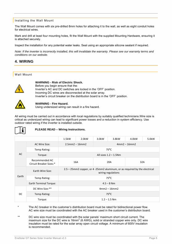
1.5kW 2.0kW 3.0kW 3.8kW 4.0kW 5.0kW
AC
AC Wire Size: 2.5mm2 – 16mm2 4mm2 – 16mm2
Temp Rating: 75⁰C
Torque: All sizes 1.2 – 1.5Nm
Recommended AC Circuit Breaker Sizes:*
16A 20A 32A
Earth
Earth Wire Size: 2.5 – 25mm2 copper, or 4 ‐25mm2 aluminum, or as required by the electrical
wiring regulations
Temp Rating: 75⁰C
Earth Terminal Torque: 4.5 – 8 Nm
DC
DC Wire Size:** 4mm2 – 16mm2
Temp Rating: 75⁰C
Torque: 1.2 – 1.5 Nm
* The AC breaker in the customer’s distribution board must be rated for bidirectional power flow.
AC wire size must be coordinated with the AC breaker used in the customer’s distribution board. ** DC wire size must be coordinated with the solar panels’ maximum short circuit current. The
maximum size for the DC wire is 16mm2 (6 AWG), solid or stranded copper wire only. DC wire insulation must be rated for the solar array open circuit voltage. A minimum of 600V insulation is recommended.

EnaSolar GT Series Solar Inverter Manual v2.3 Page 9
Wall Mount Sample Wiring - 1.5 to 3.8kW Models. This Wall Mount has an Earth Fuse fitted.
Wall Mount Sample Wiring - 4.0/5.0kW Models. This Wall Mount does not have an Earth Fuse fitted.
EnaSolar inverters are fitted with mechanically interlocked AC and DC switches which prevent access to the wiring behind the front panel while the switches are in the “on” position.
The Wall Mount has eight conduit holes. Choose appropriate conduit holes depending on the installation location. Mark DC wires to differentiate between positive and negative and between panel strings if multiple strings are being used (e.g. PV1+, PV1-, PV2+, PV2-). Route the AC wires, DC wires and Ethernet cable (if fitted) through separate conduits to the Wall Mount. Ensure all unused conduit entry points are fitted with the supplied Conduit Bungs.
Front Panel Interlocks

EnaSolar GT Series Solar Inverter Manual v2.3 Page 10
1.5-3.8kW models have one MPPT PV input and the 4.0/5.0kW models have two independent MPPT PV inputs. Each MPPT input can be connected to a single solar string or to two solar strings in parallel, provided the strings connected to the input are identical. Inputs to the 4.0/5.0kW models should not be connected together.
If multiple inverters are installed it is recommended that inverters are wired to different phases.
Strip 9mm of insulation from the AC and DC wires.
The DC terminals marked ‘-PV’ and ‘+PV’ allow wiring of two strings of panels in parallel per MPPT input. Connect the DC wires to the terminals and tighten to 1.2-1.5 Nm (10.6-13.3 Lb-In). The earth wire from the solar array frame should be connected to the earthing bar.
Screw in the antenna (Wi-Fi version) to the bottom of the Wall Mount.
If you are not installing the Inverter Module at this stage an additional Service Cover can be fitted to maintain fixed wiring protection. The Service Cover is available from your EnaSolar distributor.
Earth ing of Solar Arrays
WARNING - Risk of Electric Shock. Before you begin ensure that the inverter’s AC and DC switches are locked in the ‘OFF’ position.
Note: This section refers to earthing the positive or negative of the solar array. The panel frames should always be connected to earth.
Earth Positions – 1.5 – 3.8kW inverter
Earth Positions – 4, 4.6, 5.0kW inverter
Isolated Earth Position
Positive Earth Position
Negative Earth Position
Isolated Earth Position
Positive Earth Position
Negative Earth Position

EnaSolar GT Series Solar Inverter Manual v2.3 Page 11
Earthing Block Diagram
Some solar panels require earthing of either positive or negative DC, check with the panel manufacturer to see if this is necessary. The EnaSolar GT Series Solar Inverter provides isolated, negative or positive earthing options. Inverters use an internal 100kΩ resistence to provide functional positive or negative earthing of the panels.
Isolated Earth System (Default): The positive and negative from the solar array are isolated from earth. On startup, the inverter verifies there is >50kΩ impedance between each DC input and earth. If the inverter detects lower impedance, it will display ‘PV Earth Fault’ and the red LED will light. Depending on the inverter configuration, the inverter may continue generating in this state – see the Configuration Details section.
Any earth fault identified by the inverter must be resolved. If concurrent earth faults occur, an electrically unsafe situation exists and could result in fire. See ‘PV Earth Fault’ in the Troubleshooting section.
EnaSolar GT Series Solar Inverter Manual v2.3 Page 12
Negative or Positive Earth System: Some panels (particularly thin film) require the negative or positive wire from the solar array to be connected to earth. The electrical connection is made through a 100kΩ resistance. (Functional earth).
The functional earthing configuration is changed by moving a jumper between connectors labelled +VE Earth, -VE Earth and Isolated PV.
When configuring the inverter using the Inverter Configuration Software, be sure to select the appropriate option based on the position of the earthing jumper and whether the Earth Fuse is fitted.
Inverter Module
WARNING - Risk of Electric Shock. Before you begin ensure that the inverter’s AC and DC switches are locked in the ‘OFF’ position.
Before installing the Inverter Module ensure: Every ingress point of water and dust is sealed. No loose items, wire strands or debris
are left inside the Wall Mount. The Mounting Hardware is not over-torqued.
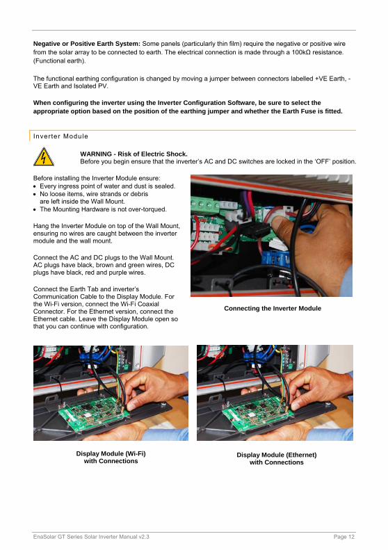
Hang the Inverter Module on top of the Wall Mount, ensuring no wires are caught between the inverter module and the wall mount.
Connect the AC and DC plugs to the Wall Mount. AC plugs have black, brown and green wires, DC plugs have black, red and purple wires.
Connect the Earth Tab and inverter’s Communication Cable to the Display Module. For the Wi-Fi version, connect the Wi-Fi Coaxial Connector. For the Ethernet version, connect the Ethernet cable. Leave the Display Module open so that you can continue with configuration.
Connecting the Inverter Module
Display Module (Wi-Fi) with Connections
Display Module (Ethernet) with Connections
EnaSolar GT Series Solar Inverter Manual v2.3 Page 13
Test ing the Vol tages
WARNING - Risk of Electric Shock. Before you begin ensure that the inverter’s AC and DC switches are locked in the ‘OFF’ position.
Re-connect the solar array or arrays and measure the voltage across the DC input terminals in the Wall Mount, when the array is exposed to daylight. To prevent damage to the Inverter this voltage must be greater than 150V DC and less than 500V DC for the 1.5-3.8kW models or 600V DC for all other models. Turn on the DC switch and measure the voltage at the DC terminals. If the DC voltage drops below 10V this indicates reversed polarity wiring from the solar array which must be resolved.
Switch on the inverter’s circuit breaker at the customer’s AC distribution board and measure the voltage at the AC terminals in the Wall Mount. The nominal voltage should be approximately 230/240V AC.
5. CONFIGURATION
Conf igurat ion Overview
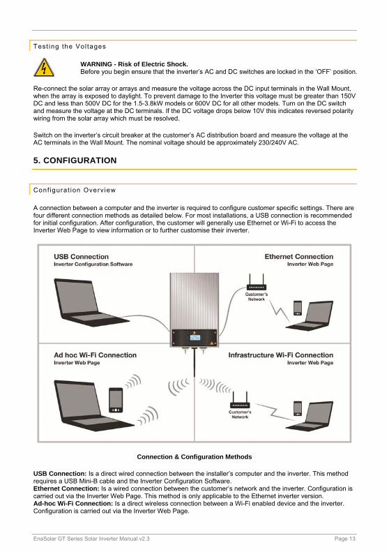
A connection between a computer and the inverter is required to configure customer specific settings. There are four different connection methods as detailed below. For most installations, a USB connection is recommended for initial configuration. After configuration, the customer will generally use Ethernet or Wi-Fi to access the Inverter Web Page to view information or to further customise their inverter.
Connection & Configuration Methods
USB Connection: Is a direct wired connection between the installer’s computer and the inverter. This method requires a USB Mini-B cable and the Inverter Configuration Software. Ethernet Connection: Is a wired connection between the customer’s network and the inverter. Configuration is carried out via the Inverter Web Page. This method is only applicable to the Ethernet inverter version. Ad-hoc Wi-Fi Connection: Is a direct wireless connection between a Wi-Fi enabled device and the inverter. Configuration is carried out via the Inverter Web Page.

EnaSolar GT Series Solar Inverter Manual v2.3 Page 14
Infrastructure Wi-Fi Connection: Is a wireless connection between the customer’s network and the inverter. Initial configuration is required via either USB or Ad-hoc Wi-Fi connection. Further setup can be carried out using the Inverter Web Page.
Configuration is carried out to enable the customer to view the inverter’s web page. The inverter will still operate without configuration.
When an inverter is connected to the customer’s network, data will be sent to EnaSolar Online, providing performance information to the customer and installer. Limited bandwidth is used when sending this data (approximately 1MB per month). This feature can be disabled through the Advanced section in the Inverter Configuration Software.
Regardless of the connection method used, the following settings should be configured. There are also advanced settings available which are explained later in this manual.
Date, Time and Time Zone: The inverter contains a clock that is used to generate charts on the Inverter Web Page and internal log files. Network Settings: Depending on your connection method and customer’s network, some settings may need to be set/changed so that the inverter can connect to the customer’s network. Solar Panel Earthing: The required PV panel earth reference. See Configuration Details. Inverter Name: Is a personalised name to be displayed at the top of the inverter’s web page. If multiple inverters are installed on a site, each name must be unique.
Once the inverter has been configured, the inverter should be commissioned - see the Commissioning the System section.
Conf igurat ion Detai ls
The DC switch should be turned ‘ON’ during configuration.
Solar Panel Earthing and advanced Grid Connect settings can only be changed using the Inverter Configuration Software through a USB connection.
Solar Panel Earthing options must be set as appropriate for each installation. See the Earthing of Solar Arrays section for more information: Earth Fault Detection Enabled – Provided for diagnostic purposes only, should be left enabled. Earthing Position – Set to either Positive, Negative, or Isolated, corresponding to the solar panel earthing selected in the Earthing of Solar Arrays section. Inverter Generates With Fault – If this is selected, then the inverter will display an error, but continue to operate, if there is less than 50kΩ earth impedance detected.
The settings section of the Inverter Web Page requires a username and password known as the “Web Administrator Username/Password”. The default username is ‘Admin’ and password ‘Admin1’, but these can be changed in the Network section of the Inverter Web Page, or in the Advanced Network tab in the Inverter Configuration Software. If the username or password is lost, see instructions for resetting the Web Administrator Username/Password in the Troubleshooting section.
An IP address is a numerical label assigned to each device on a network. From a device connected to the customer’s network or directly to the inverter via Ad-hoc, the Inverter Web Page can be accessed by entering the inverter’s IP address into a web browser (such as Chrome, Safari, Internet Explorer, etc.) as four numbers separated by dots e.g. http://192.168.1.105. When the inverter is connected to a network, its IP address will be displayed on the Network Screen – see the Using the Inverter section.
Most networks use DHCP to automatically assign an IP address to new devices connected to the network. The inverter is configured to use DHCP by default, so an IP address will generally not need to be manually set. If a static IP address needs to be assigned, this can be done in the Advanced Settings Network section of the Inverter Configuration Software.
EnaSolar GT Series Solar Inverter Manual v2.3 Page 15
The hostname is an alternative to entering the inverter’s IP address. By default the hostname is ENASOLAR-GT, meaning the customer can enter http://ENASOLAR-GT into a web browser to view the Inverter Web Page. A hostname may be up to 15 characters long and cannot contain spaces. If multiple inverters are being installed the hostname should be unique for each inverter.
Inverter Conf igurat ion Sof tware
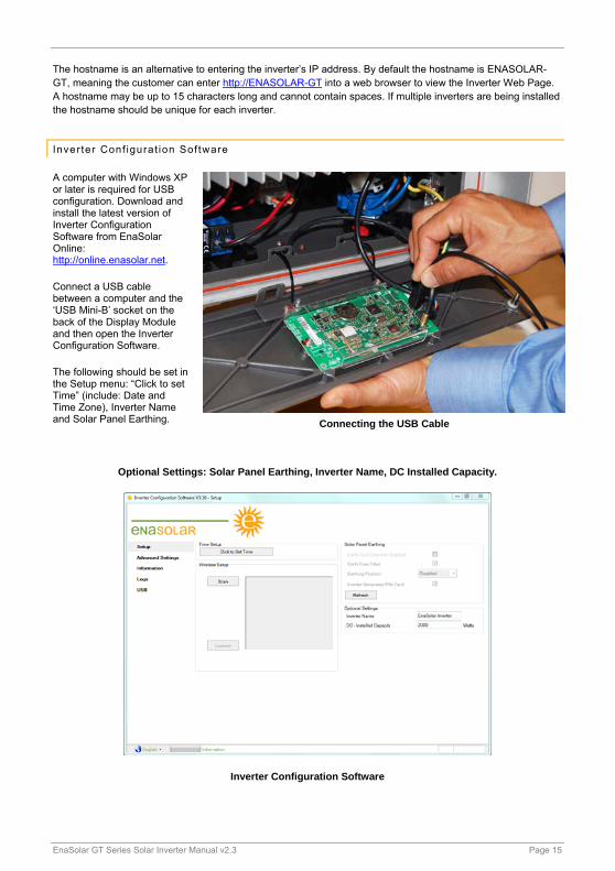
A computer with Windows XP or later is required for USB configuration. Download and install the latest version of Inverter Configuration Software from EnaSolar Online: http://online.enasolar.net.
Connect a USB cable between a computer and the ‘USB Mini-B’ socket on the back of the Display Module and then open the Inverter Configuration Software.
The following should be set in the Setup menu: “Click to set Time” (include: Date and Time Zone), Inverter Name and Solar Panel Earthing.
Optional Settings: Solar Panel Earthing, Inverter Name, DC Installed Capacity.
Inverter Configuration Software
Connecting the USB Cable
EnaSolar GT Series Solar Inverter Manual v2.3 Page 16
If a Wi-Fi inverter version is being installed, click the Scan button on the Setup page. A list of wireless networks within range of the inverter will be displayed. Select the customer’s wireless network from the list and click the Connect button. The Inverter Configuration Software will prompt for any required Wi-Fi passwords.
If an Ethernet inverter version is being installed, further settings can be found in the Advanced Settings.
Conf igurat ion through the Inverter Web Page
Most settings in the inverter can be configured through the Inverter Web Page. Either of the three network connection methods can be used to access the Inverter Web Page; see the Ethernet Connection, Ad-hoc Wi-Fi Connection or Infrastructure Wi-Fi Connection section for more information.
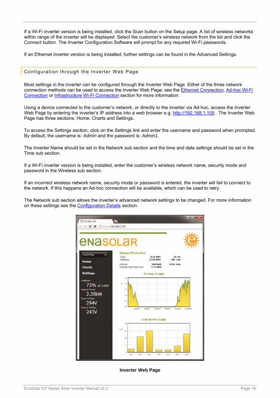
Using a device connected to the customer’s network, or directly to the inverter via Ad-hoc, access the Inverter Web Page by entering the inverter’s IP address into a web browser e.g. http://192.168.1.105 . The Inverter Web Page has three sections; Home, Charts and Settings.
To access the Settings section, click on the Settings link and enter the username and password when prompted. By default, the username is: Admin and the password is: Admin1.
The Inverter Name should be set in the Network sub section and the time and date settings should be set in the Time sub section.
If a Wi-Fi inverter version is being installed, enter the customer’s wireless network name, security mode and password in the Wireless sub section.
If an incorrect wireless network name, security mode or password is entered, the inverter will fail to connect to the network. If this happens an Ad-hoc connection will be available, which can be used to retry.
The Network sub section allows the inverter’s advanced network settings to be changed. For more information on these settings see the Configuration Details section.
Inverter Web Page

EnaSolar GT Series Solar Inverter Manual v2.3 Page 17
Ethernet Connect ion
An Ethernet connection is a direct wired connection between the customer’s network and the inverter. Ethernet connections require the Ethernet version of the inverter, rather than the standard Wi-Fi version.
Generally, there will be no additional network setup required for Ethernet connected inverters as the inverter is configured by default to common network settings (DHCP enabled). If the Display Module displays an IP Address in the Network Screen, the inverter has successfully connected to a network and configuration can proceed - see the Configuration through the Inverter Web Page section.
If the inverter fails to connect to an Ethernet network, use a USB connection to set the network settings as required by the customer’s network administrator. Relevant settings are located in the Advanced Network section of the Inverter Configuration Software.
Ad-hoc Wi-Fi Connect ion
An Ad-hoc Wi-Fi connection is a direct wireless connection between a Wi-Fi enabled device and the inverter. Ad-hoc connections give access to the Inverter Web Page. For general use, an Infrastructure Wi-Fi connection (detailed below) is preferred, because only one device at a time can be connected to the inverter via Ad-hoc.
If the inverter fails to connect to a Wi-Fi network, or none is available, the inverter will become available for connection via Ad-hoc. When the inverter is available for Ad-hoc connection, a unique 5 digit key will be displayed on the inverter’s Network Screen.
Ad-hoc Wi-Fi Connection Key
Ad-hoc Wi-Fi Connection (Mac OS)
EnaSolar GT Series Solar Inverter Manual v2.3 Page 18
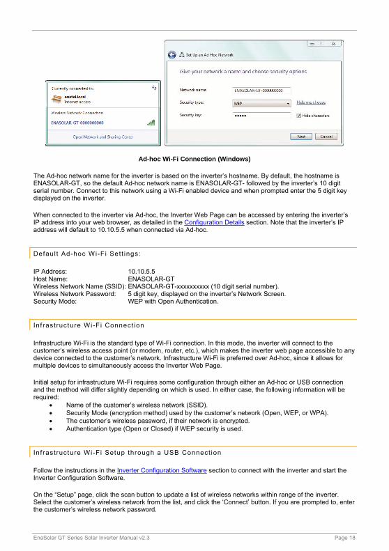
Ad-hoc Wi-Fi Connection (Windows)
The Ad-hoc network name for the inverter is based on the inverter’s hostname. By default, the hostname is ENASOLAR-GT, so the default Ad-hoc network name is ENASOLAR-GT- followed by the inverter’s 10 digit serial number. Connect to this network using a Wi-Fi enabled device and when prompted enter the 5 digit key displayed on the inverter.
When connected to the inverter via Ad-hoc, the Inverter Web Page can be accessed by entering the inverter’s IP address into your web browser, as detailed in the Configuration Details section. Note that the inverter’s IP address will default to 10.10.5.5 when connected via Ad-hoc.
Defaul t Ad-hoc Wi-Fi Set t ings:
IP Address: 10.10.5.5 Host Name: ENASOLAR-GT Wireless Network Name (SSID): ENASOLAR-GT-xxxxxxxxxx (10 digit serial number). Wireless Network Password: 5 digit key, displayed on the inverter’s Network Screen. Security Mode: WEP with Open Authentication.
Inf rastructure Wi-Fi Connect ion
Infrastructure Wi-Fi is the standard type of Wi-Fi connection. In this mode, the inverter will connect to the customer’s wireless access point (or modem, router, etc.), which makes the inverter web page accessible to any device connected to the customer’s network. Infrastructure Wi-Fi is preferred over Ad-hoc, since it allows for multiple devices to simultaneously access the Inverter Web Page.
Initial setup for infrastructure Wi-Fi requires some configuration through either an Ad-hoc or USB connection and the method will differ slightly depending on which is used. In either case, the following information will be required:
Name of the customer’s wireless network (SSID). Security Mode (encryption method) used by the customer’s network (Open, WEP, or WPA). The customer’s wireless password, if their network is encrypted. Authentication type (Open or Closed) if WEP security is used.
Inf rastructure Wi-Fi Setup through a USB Connect ion
Follow the instructions in the Inverter Configuration Software section to connect with the inverter and start the Inverter Configuration Software.
On the “Setup” page, click the scan button to update a list of wireless networks within range of the inverter. Select the customer’s wireless network from the list, and click the ‘Connect’ button. If you are prompted to, enter the customer’s wireless network password.

EnaSolar GT Series Solar Inverter Manual v2.3 Page 19
WEP authentication type will be required when connecting to a network that uses WEP. If the WEP authentication type is unknown, Open will be correct in most cases
When the inverter has successfully connected to the Wi-Fi network, a message including the inverter’s IP address will be displayed in the Inverter Configuration Software.
Infrastructure Wi-Fi Connection
Inf rastructure Wi-Fi Setup through an Ad-hoc Wi-Fi Connect ion
Connect to the inverter as detailed in the Ad-hoc Wi-Fi Connection section. Once connected, access the Inverter Web Page as in the Configuration through the Inverter Web Page section. Fill in the appropriate information in the Wireless Network section of the Inverter Web Page. The inverter will attempt to connect to the newly specified network after the Apply Settings button is clicked. If the connection fails, the inverter will again be available for an Ad-hoc connection.
Note: If any of the above fails - refer to the Network Troubleshooting section. More advanced settings can be found on the advanced settings page.
EnaSolar GT Series Solar Inverter Manual v2.3 Page 20
6. COMMISSIONING THE SYSTEM
Fit t ing the Display Module
Remove the USB cable and place the Display Module on the Inverter Module, ensuring that no wires are pinched between the Wall Mount and the Display Module.
Tighten the top two screws on the Display Module then press in the bottom of the inverter before tightening the bottom two screws. Turn the AC and DC switches to the ‘ON’ position. If there is power from the solar array, the inverter will start generating. See the Troubleshooting section if an error is displayed.
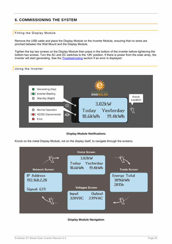
Using the Inverter
Display Module Notifications
Knock on the metal Display Module, not on the display itself, to navigate through the screens.
Display Module Navigation

EnaSolar GT Series Solar Inverter Manual v2.3 Page 21
The navigation screens show different aspects of the inverter’s operation as detailed below: Home Screen: Current power production or status, today and yesterday’s energy production. Totals Screen: Lifetime energy production and generating time. Voltages Screen: Input and output voltages. Network Screen: Inverters IP address, networking state,
Ad-hoc password and/or Wi-Fi signal strength as appropriate. Event Screen: If an abnormal event occurs, an additional screen
detailing the event will be displayed prior to the Home Screen.
Stopping the Inverter
Turn the AC and DC switches ‘OFF’. The inverter will stop generating and the red LED will flash.
Maintenance
The inverter requires very little maintenance. Use a soft damp cloth to clean the outside of the inverter as required. Keep the Inverter Module free of cobwebs, leaves etc.
If the inverter is installed in a salty environment, gently rinse the inverter with a low pressure hose.
7. ADVANCED USAGE
The inverter maintains three log files internally, to track output and to aid in diagnostics in the event of a failure:
Daily Log: The amount of power produced each day and the amount of time spent exporting power to the grid.
5 Minute Log: Logs the output power every 5 minutes.
Event Log: Logs any unusual events that occur to diagnose potential faults. Blank lines mean that all events were cleared at that time.
The Daily Log and 5 Minute Log are available to the customer through the Inverter Web Page. The Event Log is intended only for use by EnaSolar and certified installers. All three logs are available through the Inverter Configuration Software in the Logs page.
To read logs through the Inverter Web Page, click the Export Daily Log or Export 5 Minute Log button at the bottom of the Charts section. The log file will be downloaded to your computer as a Comma Separated Value (.CSV) file, which can be opened in spread sheet software.
Warranty Information
To validate the warranty all inverters must be registered within 30 days of installation, by completing the new installation form within EnaSolar Online: http://online.enasolar.net.
EnaSolar will not be held responsible for indirect or consequential damages or lost profits, even if EnaSolar has been advised of the possibility of such damages. EnaSolar’s sole
obligation to you shall be the repair or replacement of a non-conforming product.
Standard warranty terms and conditions are available at: www.enasolar.net/warrantyterms
EnaSolar GT Series Solar Inverter Manual v2.3 Page 22
Advanced Set t ings
Several tabs are available in the Advanced Settings page of the Inverter Configuration Software. These tabs contain settings that might be relevant in certain circumstances. These settings will generally not need to be changed:
Advanced Sett ings - Network
The Network Connection Details section shows the current details for the inverter’s network interface. The Network Settings section allows the inverter network interface settings to be changed.
If DHCP is disabled then the Default IP Address, Default Subnet Mask, Default Gateway, Default Primary DNS Server and Default Secondary DNS Server will need to be set manually. The Gateway and DNS should usually be set to the local IP address of the router or access point.
The Web Administrator Username and Password that are used to log into and gain access to the settings web pages can be changed using this screen. Consult the customer for their preference.
The Wireless Settings section allows the wireless settings to be changed at a lower level than is generally required. Changing the region and deselecting scan channels is not advised.
Remote monitoring can be disabled by selecting the check box. By doing this there will be no performance or event information sent to EnaSolar Online.
Advanced Sett ings - Gr id Connect
Grid connect settings control the limits of AC mains quality where the inverter will output power. The inverter will disconnect if it detects that the AC voltage or frequency goes outside the limits defined for specified amounts of time.
Default grid connect settings are based on regulations in effect for the country where the inverter is sold. These limits can usually be changed, but permission from the relevant electricity distributor will be required. Contact EnaSolar ([email protected] or +64-3-366 4550) for more information on changing Grid Connect Settings, if required.
Advanced Set t ings - Other
Stop Red LED Flashing – After the inverter is powered on for the first time, if both AC mains and the DC supply are disconnected (or switched ‘OFF’), the red LED on the Display Module will periodically flash. Normally, this indicates that there is a mains fault and no DC supply. If, however, the Display Module needs to be stored for several weeks, this flashing would eventually drain the small battery in the Display Module. When long term storage of the Display Module is required, the “Stop LED” button can be pressed, which will prevent the red LED from flashing once power is disconnected. The red LED will resume normal operation upon next power up.
Totals section - Two boxes allow the total energy output and time generating to be changed. This feature is useful if the Display Module requires replacement.
Copy Display Module Settings and Daily Log - This section is used to backup and restore the settings from the inverter’s Display Module. Use the Read button to store these settings as a file on your computer, or the Write button to write the file back to a Display Module. This feature is intended for duplicating network settings for multi-inverter installs, or for backing up the Daily Log in case the Display Module requires replacement.
Several settings pertaining to MPPT are available on newer inverters, see the enasolar website for application notes as required.
EnaSolar GT Series Solar Inverter Manual v2.3 Page 23
8. TROUBLESHOOTING
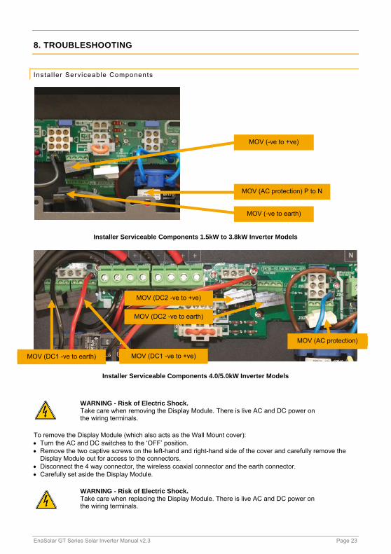
Insta l ler Serviceable Components
Installer Serviceable Components 1.5kW to 3.8kW Inverter Models
Installer Serviceable Components 4.0/5.0kW Inverter Models
WARNING - Risk of Electric Shock. Take care when removing the Display Module. There is live AC and DC power on the wiring terminals.
To remove the Display Module (which also acts as the Wall Mount cover): Turn the AC and DC switches to the ‘OFF’ position. Remove the two captive screws on the left-hand and right-hand side of the cover and carefully remove the
Display Module out for access to the connectors. Disconnect the 4 way connector, the wireless coaxial connector and the earth connector. Carefully set aside the Display Module.
WARNING - Risk of Electric Shock. Take care when replacing the Display Module. There is live AC and DC power on the wiring terminals.
MOV (-ve to +ve)
MOV (AC protection) P to N
MOV (-ve to earth)
MOV (DC1 -ve to earth) MOV (DC1 -ve to +ve)
MOV (DC2 -ve to +ve)
MOV (DC2 -ve to earth)
MOV (AC protection)
EnaSolar GT Series Solar Inverter Manual v2.3 Page 24
To replace the Display Module: Ensure the AC and DC switches are in the ‘OFF’ position. Connect the 4 way connector, the wireless coaxial connector and the earth connector. Place the cover on the Inverter Module, ensuring that no wires are pinched between the Wall Mount and the
cover. Replace the two captive screws on the left-hand and right-hand side of the cover and tighten securely.
If a replacement Display Module is required to be fitted, the historic data that has been saved on the older unit can be transferred by using the transfer function on the Inverter Configuration Software. This can be found within the ‘Advanced Settings’ page under the tab labelled ‘Other’.
Genera l Troubleshoot ing
NO DC: Check that the DC switch is turned ‘ON’, the solar array is fully exposed to sunlight and the polarity of the DC input.
NO AC: Check that the AC switch is turned ‘ON’ and the AC circuit breaker is on at the switchboard.
PV Earth Fault: Isolated Earth - this means there is less than 50kΩ between the positive or negative DC input and earth. That is the cabling for the solar array has developed a fault from either the positive or negative input to ground. This will display the message ‘PV Earth Fault’ and will continue to operate.
Although the inverter will continue to operate as an isolated earth installation, this is a fault that needs to be urgently addressed. A ‘PV Earth Fault’ does not necessarily indicate an unsafe situation, but a subsequent fault could result in a fire and safety risk.
Possible causes: Faulty cell in one of the solar modules. Cracked/corroded/damage solar module. Chaffed or damaged wiring. Incorrect wiring or configuration. Water between connections.
The inverter has internal impedances, so before making any impedance measurements ensure the DC switch is turned ‘OFF’. To help diagnose where the problem lies, while the inverter is running, measure the following voltages: positive to negative, positive to ground and negative to ground. By comparing these values, this will give an indication where the problem lies.
PV Earth Fuse: Positive or negative earth - If this alarm is generated, a current greater than 1A has blown the Earth Fuse. Once the fault has been rectified, the fuse will need to be replaced. See below for the procedure.
WARNING - Risk of Electric Shock. The PV Earth Fuse must only be replaced by a trained solar technician.
Ensure the AC and DC switches are turned ‘OFF’. De-energise both the AC (from the switchboard) and DC (Solar array) feeds into the inverter. Gain access to the Wall Mount by removing the Display Module. Check if the Earth Fuse is open and leave the fuse holder open. Inspect the solar array for any possible cause of the fault and remedy as required. Replace the fuse with - 1A, 600V DC Littlefuse KLKD 1 Refit the Display Module and re-energise the system.
EnaSolar GT Series Solar Inverter Manual v2.3 Page 25
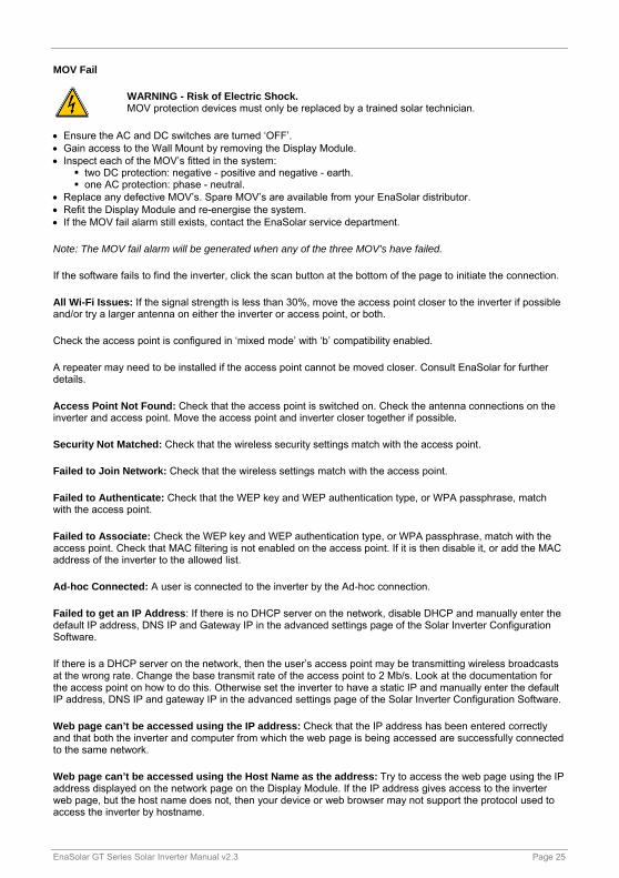
MOV Fail
WARNING - Risk of Electric Shock. MOV protection devices must only be replaced by a trained solar technician.
Ensure the AC and DC switches are turned ‘OFF’. Gain access to the Wall Mount by removing the Display Module. Inspect each of the MOV’s fitted in the system:
two DC protection: negative - positive and negative - earth. one AC protection: phase - neutral.
Replace any defective MOV’s. Spare MOV’s are available from your EnaSolar distributor. Refit the Display Module and re-energise the system. If the MOV fail alarm still exists, contact the EnaSolar service department.
Note: The MOV fail alarm will be generated when any of the three MOV’s have failed.
If the software fails to find the inverter, click the scan button at the bottom of the page to initiate the connection.
All Wi-Fi Issues: If the signal strength is less than 30%, move the access point closer to the inverter if possible and/or try a larger antenna on either the inverter or access point, or both.
Check the access point is configured in ‘mixed mode’ with ‘b’ compatibility enabled.
A repeater may need to be installed if the access point cannot be moved closer. Consult EnaSolar for further details.
Access Point Not Found: Check that the access point is switched on. Check the antenna connections on the inverter and access point. Move the access point and inverter closer together if possible.
Security Not Matched: Check that the wireless security settings match with the access point.
Failed to Join Network: Check that the wireless settings match with the access point.
Failed to Authenticate: Check that the WEP key and WEP authentication type, or WPA passphrase, match with the access point.
Failed to Associate: Check the WEP key and WEP authentication type, or WPA passphrase, match with the access point. Check that MAC filtering is not enabled on the access point. If it is then disable it, or add the MAC address of the inverter to the allowed list.
Ad-hoc Connected: A user is connected to the inverter by the Ad-hoc connection.
Failed to get an IP Address: If there is no DHCP server on the network, disable DHCP and manually enter the default IP address, DNS IP and Gateway IP in the advanced settings page of the Solar Inverter Configuration Software.
If there is a DHCP server on the network, then the user’s access point may be transmitting wireless broadcasts at the wrong rate. Change the base transmit rate of the access point to 2 Mb/s. Look at the documentation for the access point on how to do this. Otherwise set the inverter to have a static IP and manually enter the default IP address, DNS IP and gateway IP in the advanced settings page of the Solar Inverter Configuration Software.
Web page can’t be accessed using the IP address: Check that the IP address has been entered correctly and that both the inverter and computer from which the web page is being accessed are successfully connected to the same network.
Web page can’t be accessed using the Host Name as the address: Try to access the web page using the IP address displayed on the network page on the Display Module. If the IP address gives access to the inverter web page, but the host name does not, then your device or web browser may not support the protocol used to access the inverter by hostname.
EnaSolar GT Series Solar Inverter Manual v2.3 Page 26
Lost or Forgotten Password: The username and password ‘Admin’ and ‘Admin1’ will always allow access to the Settings section of the Inverter Web Page when connected via Ad-hoc - see Ad-hoc Wi-Fi Connection section. Once connected, the web administrator username and password can be changed in the Network Settings section.
Since the inverter will not be available for Ad-hoc connections while it is connected to an Infrastructure Wi-Fi network, the inverter may first need to be disconnected from the customer’s Wi-Fi network. The simplest approach is to turn off the customer’s Wi-Fi access point (router, modem, etc.) until an Ad-hoc connection with the inverter has been established.
9. UNDERSTANDING THE PART NUMBER
Example: 1.5kWGT-AUNZE
1.5kW: Nominal output power.
GT: Grid tied.
AUNZ: This is the country identifier which has the specific parameters for the grid connect settings for that country. AUNZ (Australia/New Zealand) uses the same settings as they are both governed by the AS4777 regulations. For the UK (United Kingdom) the settings are governed by the G83/1-1 regulations.
E: Identifies the inverter is fitted with the Ethernet version of Display Module. There are two versions of Display Module: Ethernet and Wi-Fi. Wi-Fi is standard and if fitted there will be no ‘E’ in the part number. E.g. 1.5kWGT-AUNZ.
10. GLOSSARY
Nm Newton metre.
LED Light emitting diode.
Lb-In Pounds-inches.
LCD Liquid crystal display.
PV Photovoltaic.
AC Alternating current.
DC Direct current.
MOV Metal oxide varistor.
GFDI Ground fault detector interrupter. A fuse between earth and a solar panel DC output that interrupts excessive fault current.
EnaSolar GT Series Solar Inverter Manual v2.3 Page 27
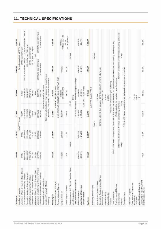
11. TECHNICAL SPECIFICATIONS

EnaSolar GT Series Solar Inverter Manual v2.3 Page 28