EN Installation & Operating Instructions WATER …€¦ · ES Instrucciones de Instalación &...
136
© 2018 erie water treatment OM-PF-SOF-Rev2018.01 EN Installation & Operating Instructions WATER SOFTENER FR Instructions d’Installation & Emploi ADOUCISSEUR D’EAU DE Installation- & Gebrauchsanleitung WASSERENTHÄRTER NL Installatie & Gebruiksinstructies WATERONTHARDER ES Instrucciones de Instalación & Servicio DESCALCIFICADOR DE AGUA PL Instrukcja Instalacji i Eksploatacji ZMIĘKCZANIA WODY Models: PF-SOF1-SIM PF-SOF1-ALT PF-SOF1-PRL PF-SOF1,5-SIM PF-SOF1,5-ALT PF-SOF1,5-PRL PF-BTA
Transcript of EN Installation & Operating Instructions WATER …€¦ · ES Instrucciones de Instalación &...

© 2018 erie water treatment OM-PF-SOF-Rev2018.01
EN Installation & Operating Instructions
WATER SOFTENER
FR Instructions d’Installation & Emploi
ADOUCISSEUR D’EAU
DE Installation- & Gebrauchsanleitung
WASSERENTHÄRTER
NL Installatie & Gebruiksinstructies
WATERONTHARDER
ES Instrucciones de Instalación & Servicio
DESCALCIFICADOR DE AGUA
PL Instrukcja Instalacji i Eksploatacji
ZMIĘKCZANIA WODY
Models: PF-SOF1-SIM PF-SOF1-ALT PF-SOF1-PRL PF-SOF1,5-SIM PF-SOF1,5-ALT PF-SOF1,5-PRL PF-BTA

EN English .......................................................................................................................... Page 3
FR Français ........................................................................................................................ Page 25
DE Deutsch ........................................................................................................................ Seite 47
NL Nederlands ................................................................................................................... Pagina 69
ES Español ......................................................................................................................... Página 98
PL Polski ............................................................................................................................ Strona 123

TABLE OF CONTENT & INSTALLATION RECORD
Page 3 EN - English
Table of content & Installation record ..................................................................................... Page 3
Warning & Safety instructions ................................................................................................. Page 4
Operating conditions & Requirements .................................................................................... Page 5
Assembly .................................................................................................................................. Page 6
Installation ............................................................................................................................... Page 8
Commissioning ......................................................................................................................... Page 10
Electronic control panel ........................................................................................................... Page 11
Maintenance ............................................................................................................................ Page 18
Composition overview ............................................................................................................. Page 19
Technical data - PF-SOF1 .......................................................................................................... Page 20
Technical data - PF-SOF1,5 ....................................................................................................... Page 22
Technical data - PF-BTA ............................................................................................................ Page 24
For future reference, fill in the following data
INSTALLATION RECORD Serial number: _______________________________________________
Model: ________________________________________________________ Water hardness-inlet: _______________________________________ Water hardness-outlet: _____________________________________ Water pressure-inlet: ________________________________________
Date of installation: __________________________________________
Company name: _____________________________________________
Installer name: _______________________________________________ Phone number: ______________________________________________

WARNING & SAFETY INSTRUCTIONS
EN - English Page 4
• Before you begin the installation of the appliance, we advise you read and carefully follow the instructions contained in this manual. It contains important information about safety, installation, use and maintenance of the product. The actual system that you have received, may differ from the pictures/illustrations/descriptions in these Instructions.
• Failure to follow the instructions could cause personal injury or damage
to the appliance or property. Only when installed, commissioned and serviced correctly, the appliance will offer you many years of trouble-free operation.
• The appliance is intended to 'soften' the water, meaning it will remove
hardness minerals; it will not necessarily remove other contaminants present in the water. The appliance will not purify polluted water or make it safe to drink!
• Installation of the appliance should only be undertaken by a competent
person, aware of the local codes in force. All plumbing and electrical connections must be done in accordance with local codes.
• Before setting up the appliance, make sure to check it for any externally
visible damage; do not install or use when damaged. • Use a hand truck to transport the appliance. To prevent accident or
injury, do not hoist the appliance over your shoulder. Do not lay the appliance on its side.
• Keep these Instructions in a safe place and ensure that new users are
familiar with the content. • The appliance is designed and manufactured in accordance with current
safety requirements and regulations. Incorrect repairs can result in unforeseen danger for the user, for which the manufacturer cannot be held responsible. Therefore repairs should only be undertaken by a competent technician, familiar and trained for this product.
• In respect of the environment, this appliance should be disposed of in
accordance with Waste Electrical and Electronic Equipment requirements. Refer to national/local laws and codes for correct recycling of this appliance.

OPERATING CONDITIONS & REQUIREMENTS
Page 5 EN - English
• OPERATING PRESSURE MIN-MAX: 1,4-8,0 bar / 20-116 psi this appliance is configured to perform optimally at an
operating pressure of 3 bar (45 psi) ±½ bar (7 psi); in case of a lower or higher operating pressure the performance may be affected negatively!
check water pressure regularly; it may fluctuate severely depending on the time of day, the day of the week or even the season of the year.
take into account that night time water pressure may be considerably higher than day time water pressure.
install a pressure reducer ahead of the appliance if necessary.
install a pressure booster, if it is likely that water pressure may drop below the minimum.
• OPERATING TEMPERATURE MIN-MAX: 2-48 °C / 35-120 °F do not install the appliance in an environment where high
ambient temperatures (e.g. unvented boiler house) or freezing temperatures can occur.
the appliance cannot be exposed to outdoor elements, such as direct sunlight or atmospheric precipitation.
do not install the appliance too close to a water heater; keep at least 3 m (10 ft) of piping between the outlet of the appliance and the inlet of the water heater; water heaters can sometimes transmit heat back down the cold pipe into the appliance; always install a check valve at the outlet of the appliance.
• ELECTRICAL CONNECTION: this appliance only works on 24 V; always use it in combination
with the supplied transformer.
in case of damage to the power supply cable of the transformer, immediately disconnect the transformer from the power outlet and replace the transformer.
make sure to plug the transformer into a power outlet, which is installed in a dry location, with the proper rating and over-current protection.

ASSEMBLY
EN - English Page 6
CONTENT CHECK
Actual parts that you have received, may differ from the pictures/illustrations in these Instructions!
For ease of transportation and installation, the softening resin is NOT loaded in the pressure tank, but delivered in separate bags of 25 ltr; it must be loaded on-site, after positioning of the pressure tank.
Check the content of the system, using the Composition Overview at the end of these Instructions. Identify and lay-out the different components to facilitate the assembly.
SIMPLEX (PF-SOF1-SIM & PF-SOF1,5-SIM)
A Simplex system consists of 1 single softening module (pressure tank, resin, control valve and accessories).
During normal operation, the Simplex system delivers softened water. As soon as it initiates a regeneration, it automatically goes into hard water bypass, guaranteeing uninterrupted supply of untreated water It is possible to upgrade a Simplex system to a Duplex Parallel system, by adding a second Simplex system.
DUPLEX ALTERNATING (PF-SOF1-ALT & PF-SOF1,5-ALT)
A Duplex ALTERNATING system consists of 2 Simplex systems, that: - are hydraulically installed in parallel; - are electronically interconnected by means of an
InterConnect cable; - have a Normally Closed solenoid operated diaphragm
valve (so called Service Valve) in the outlet of each Simplex system; this Service Valve is controlled by the electronic timer of the Simplex system and is activated during the service cycle to open the outlet of the respective Simplex system;
- share 1 brine tank, that contains 2 brine valves. During normal operation, only 1 of the 2 Simplex systems is in service, while the other one is regenerating or ‘in standby’! As soon as the first Simplex system initiates a regeneration, the second system goes into service, guaranteeing uninterrupted supply of treated water. In case of a power failure, both Service Valves will be deactivated, meaning the outlet of both Simplex systems will be closed off, cutting off the water supply (potentially hard water!) to the application.
DUPLEX PARALLEL (PF-SOF1-PRL & PF-SOF1,5-PRL)
A Duplex PARALLEL system consists of 2 Simplex systems, that: - are hydraulically installed in parallel; - are electronically interconnected by means of an
InterConnect cable; - have a Normally Open solenoid operated diaphragm valve
(so called Service Valve) in the outlet of each Simplex
system; this Service Valve is controlled by the electronic timer of the Simplex system and is activated during the entire duration of the regeneration, to close-off the control valve's standard 'hard water bypass during regeneration';
- share 1 brine tank, that contains 2 brine valves. During normal operation, both Simplex systems are in service, doubling the service flow rate! When one of the Simplex systems initiates a regeneration, it immediately communicates it's status to the other Simplex system via the InterConnect cable, to make sure the other Simplex system remains in service, guaranteeing uninterrupted supply of treated water. In case of a power failure, both Service Valves will be deactivated, meaning the outlet of both Simplex systems will be open, guaranteeing uninterrupted supply of water. For correct assembly, repeat the different assembly steps, until both Simplex systems are assembled and positioned correctly. For large installations, with an important need for treated water, 2 or more Duplex systems can easily be installed in parallel hydraulically, to double/triple/... the flow rate and softening capacity.
RESIN LOADING
1. Move the pressure tank to the correct installation
location; position it on a flat and level surface. Make sure to leave enough space for ease of service.
2. Position the riser assembly upright and centred in the pressure tank; plug the top of the riser tube with a piece of tape or clean rag, to prevent resin from entering the tube.
3. Add water to the pressure tank to a height of ±30 cm from the bottom; this water will protect the bottom of the pressure tank and the bottom distributor, during filling of the pressure tank.
4. Place a funnel on the pressure tank opening and fill the pressure tank with resin; make sure the riser assembly remains centered in the pressure tank.
5. Rinse the pressure tank opening to remove any resin beads from the threaded section.
6. Unplug the top of the riser tube.
CONTROL VALVE
only for PF-SOF1
1. Make sure the O-ring in the riser insert and the tank O-
ring (around the threaded section of the control valve) are in the correct position.
2. Screw the top distributor onto the control valve. 3. Lubricate the threaded section of the pressure tank, the
top of the riser tube and the tank O-ring of the control valve; use a silicon-based lubricant.
4. Lower the control valve straight down onto the riser tube, until the riser tube is correctly inserted in the riser insert; then push it down firmly and screw it onto the pressure tank.

ASSEMBLY
Page 7 EN - English
only for PF-SOF1,5
Picture 1
1. On the brass valve seat:
• make sure the O-ring in the riser insert is in the correct position;
• install the top distributor and fix it by means of the 2 stainless steel screws;
• install the tank O-ring in the groove on the flange around the threaded section.
2. Lubricate the threaded section of the pressure tank, the top of the riser tube and the tank O-ring of the valve seat; use a silicon-based lubricant.
3. Lower the valve seat straight down onto the riser tube, until the riser tube is correctly inserted in the riser insert inside the valve seat; then push it down firmly and screw it onto the pressure tank.
4. Install the valve seat O-ring in the groove on the valve seat.
5. Install the control valve onto the valve seat; mind the alignment pin!
6. Bolt the control valve to the valve seat by means of the 4 stainless steel bolts; tighten firmly.
BRINE TANK ASSEMBLY (PF-BTA) (optional)
Picture 2&3
1. Move the brine tank to the correct installation location; position it on a flat and level surface. Make sure to leave enough space for ease of service.
2. Insert the polytube into the brine line connection on the control valve (); make sure to push the polytube in all the way; tighten the nut.
3. Remove the lid from the brine tank. 4. Remove the lid from the brine well. 5. Make sure the correct elbow connection is installed on
the brine valve (⅜” for PF-SOF1 or ½” for PF-SOF1,5); replace if necessary.
6. Run the polytube from the control valve through the hole in the sidewall of the brine tank, to the inside of the brine tank.
7. Only for PF-SOF1,5: insert the reinforcement tube in the end of the ½” polytube.
8. Insert the polytube into the elbow connection on the brine valve; make sure to push the polytube in all the way.
9. Only for PF-SOF1,5: tighten the nut. 10. Install the lid on the brine well. 11. Add water to the brine tank to a height of ±10 cm from
the bottom. 12. Add salt to the brine tank. 13. Install the lid on the brine tank.

INSTALLATION
EN - English Page 8
INLET & OUTLET
In case of high concentration of impurities in the inlet water, we recommend the installation of a sediment filter, ahead of the appliance.
We strongly recommend the use of flexible hoses to connect the appliance to the water distribution system; use hoses with a large diameter in order to limit the pressure loss.
We strongly recommend the installation of a bypass system (not included with this product!) to isolate the appliance from the water distribution system in case of repairs. It allows to turn off the water to the appliance, while maintaining full-flow (untreated) water supply to the user.
only for PF-SOF1-SIM: SIMPLEX with factory bypass (optional)
Picture 4
= mains water supply (untreated water) ❖ = inlet of control valve (untreated water) = outlet of control valve (treated water) = application (treated water) 1. Screw the factory bypass onto the in/out ports on the
control valve (❖&); make sure to install the gasket seals. Tighten the nuts firmly by hand.
2. Screw the connection kit with nuts onto the factory bypass (&); make sure to install the gasket seals. Tighten the nuts firmly by hand.
3. Connect the mains water supply to the adaptor on the inlet port of the factory bypass ().
4. Connect the application to the adaptor on the outlet port of the factory bypass ().
only for PF-SOF1-SIM: SIMPLEX with 3-valve connection kit (not included)
Picture 5
= inlet of control valve (untreated water) ❖ = outlet of control valve (treated water) 1. Install the 3-valve connection kit. 2. Screw the connection kit with nuts onto the in/out ports
on the control valve (&❖); make sure to install the gasket seals. Tighten the nuts firmly by hand.
3. Connect the IN valve of the 3-valve connection kit to the adaptor on the in port of the control valve ().
4. Connect the OUT valve of the 3-valve connection kit to the adaptor on the out port of the control valve (❖).
5. Connect the mains water supply to the inlet of the 3-valve connection kit.
6. Connect the application to the outlet of the 3-valve connection kit.
only for PF-SOF1-ALT and PF-SOF1-PRL: DUPLEX with multiple valve connection kit (not incl.)
Picture 6
= inlet of control valve (untreated water) ❖ = outlet of control valve (treated water) = Service Valve
1. Install the multiple valve connection kit. 2. Screw the connection kit with nuts onto the in/out ports
on the control valve (&❖); make sure to install the gasket seals. Tighten the nuts firmly by hand.
3. Screw the Service Valve () onto the adaptor at the out port of the control valve (❖); make sure to respect the flow direction (see indication arrow on the bottom of the Service Valve); use an appropriate sealant.
4. Connect the IN valve of the multiple valve connection kit to the adaptor on the in port of the control valve ().
5. Connect the OUT valve of the multiple valve connection kit to the outlet of the Service Valve ().
6. Repeat steps 2-5 for both Simplex systems. 7. Connect the mains water supply to the inlet of the
multiple valve connection kit. 8. Connect the application to the outlet of the multiple valve
connection kit.
only for PF-SOF1,5-SIM: SIMPLEX with 3-valve connection kit (not incl.)
Picture 7
= inlet of control valve (untreated water) ❖ = outlet of control valve (treated water) = PVC elbow = inlet of flow meter = outlet of flow meter 1. Install the 3-valve connection kit. 2. Insert the adaptors in the in/out ports on the control valve
(&❖); make sure not to damage the O-rings. Install the nuts and tighten them firmly by hand.
3. Screw the PVC elbow () onto the adaptor at the out port of the control valve (❖); use an appropriate sealant.
4. Insert the adaptors in the in/out ports on the flow meter (&); make sure not to damage the O-rings. Install the nuts and tighten them firmly by hand.
5. Screw the flow meter () into the PVC elbow (); make sure to respect the flow direction (see indication arrow); use an appropriate sealant.
6. Connect the flow meter cable from the control valve to the flow meter; secure it by means of the screw.
7. Connect the IN valve of the 3-valve connection kit to the adaptor on the in port of the control valve ().
8. Connect the OUT valve of the 3-valve connection kit to the adaptor on the out port of the flow meter ().
9. Connect the mains water supply to the inlet of the 3-valve connection kit.
10. Connect the application to the outlet of the 3-valve connection kit.
only for PF-SOF1,5-ALT and PF-SOF1,5-PRL: DUPLEX with multiple valve connection kit (not incl.)
Picture 8
= inlet of control valve (untreated water) ❖ = outlet of control valve (treated water) = PVC elbow = inlet of flow meter = outlet of flow meter = Service Valve 1. Install the multiple valve connection kit. 2. Insert the adaptors in the in/out ports on the control valve
(&❖); make sure not to damage the O-rings. Install the nuts and tighten them firmly by hand.

INSTALLATION
Page 9 EN - English
3. Screw the PVC elbow () onto the adaptor at the out port of the control valve (❖); use an appropriate sealant.
4. Insert the adaptors in the in/out ports on the flow meter (&); make sure not to damage the O-rings. Install the nuts and tighten them firmly by hand.
5. Screw the flow meter () into the PVC elbow (); make sure to respect the flow direction (see indication arrow); use an appropriate sealant.
6. Connect the flow meter cable from the control valve to the flow meter; secure it by means of the screw.
7. Screw the Service Valve () onto the adaptor on the out port of the flow meter (); make sure to respect the flow direction (see indication arrow on the bottom of the Service Valve); use an appropriate sealant.
8. Connect the IN valve of the multiple valve connection kit to the adaptor on the in port of the control valve ().
9. Connect the OUT valve of the multiple valve connection kit to the outlet of the Service Valve ().
10. Repeat steps 2-8 for both Simplex systems. 11. Connect the mains water supply to the inlet of the
multiple valve connection kit. 12. Connect the application to the outlet of the multiple valve
connection kit.
DRAIN
We recommend the use of a stand pipe with P-trap.
To prevent backflow from the sewerage system into the appliance, always ensure sufficient air gap between the end of the drain hose or pipe and the sewerage system.
Always use separate drain hoses for the control valve(s) (discharge of rinse water) and the brine tank overflow.
Lay-out the drain hoses in such a way that pressure loss is minimized; avoid kinks and unnecessary elevations.
Make sure that the sewerage system is suitable for the rinse water flow rate of the appliance.
only for PF-SOF1
Picture 9
1. Connect the 19 mm hose to the drain connection of the control valve (); secure it by means of the clamp.
2. Run the drain hose to the sewerage system and connect it, ensuring sufficient air gap between the end of the hose and the sewerage system. This drain line operates under pressure, so it may be installed higher than the appliance.
3. For Duplex: repeat steps 1-2 for both Simplex systems.
only for PF-SOF1,5
Picture 10
1. Connect a pipe to the 1” BSP Male drain connection of the control valve (); use an appropriate sealant.
2. Run the pipe to the sewerage system and connect it, ensuring sufficient air gap between the end of the pipe and the sewerage system. This drain line operates under pressure, so it may be installed higher than the appliance.
3. For Duplex: repeat steps 1-2 for both Simplex systems.
PF-BTA: brine tank assembly (optional)
1. Connect the 19 mm hose to the overflow elbow on the brine tank; secure it by means of the clamp.
2. Run the drain hose to the sewerage system and connect it, ensuring sufficient air gap between the end of the hose and the sewerage system. This drain line does NOT operate under pressure, so it may NOT be installed higher than the brine tank.
SERVICE VALVES
(only for Duplex)
Picture 11
1. Plug the DIN plug on the connection cable of the Service Valve into the DIN socket at the back of the electronic timer head of the respective control valve ().

COMMISSIONING
EN - English Page 10
ELECTRICAL
1. Connect the appliances power cord to the transformers
output. 2. Plug the transformer into an electrical outlet.
PRESSURIZING 1. Put the bypass system in 'bypass' position. 2. Make sure the electronic controller(s) of the appliance is
(are) in service mode. 3. Open the mains water supply. 4. Open a cold treated water faucet nearby the appliance
and let the water run for a few minutes until all air is purged and all foreign material that may have resulted from the installation is washed out; close the tap.
5. Gently pressurize the appliance, by putting it into service:
• close the 'BYPASS' valve;
• open the 'OUT' valve;
• slowly open the 'IN' valve. 6. After 2-3 minutes, open a cold treated water faucet
nearby the appliance and let the water run for a few minutes until all air is purged from the installation and the resin bed is rinsed (it is normal for the rinse water to show some discoloration!); close the tap.
7. Check the appliance and all hydraulic connections for leaks.
8. For Duplex: repeat steps 5-7 for both Simplex systems.
ELECTRONIC CONTROL PANEL
1. Program the electronic controller. 2. For Duplex: repeat step 1 for both Simplex systems.
ADJUSTMENT RESIDUAL HARDNESS (only for PF-SOF1)
In practice the residual hardness is influenced by the inlet pressure, flow rate and hardness of the incoming untreated water. When adjusting the residual hardness, make sure these conditions are similar to the actual operating conditions.
ON CONTROL VALVE
Picture 12.a
1. Adjust the residual hardness of the water that leaves the softener, by means of the adjusting screw, incorporated at the right side of the control valve:
• to raise the residual hardness: turn the screw counter clockwise;
• to reduce the residual hardness: turn the screw clockwise.
2. Measure the residual water hardness with a water hardness test kit; readjust if necessary.
WITH FACTORY BYPASS (optional)
Picture 12.b
1. Adjust the residual hardness of the water that leaves the softener, by means of the adjusting screw, incorporated in the 'outlet' valve of the factory bypass:
• to raise the residual hardness: turn the screw counter clockwise.
• to reduce the residual hardness: turn the screw clockwise.
2. Measure the residual water hardness with a water hardness test kit; readjust if necessary.
INITIATE A REGENERATION
1. Manually initiate a regeneration, by pressing the scroll
button; the display will show: 2. Leave the appliance in this position; the count-down
timer will count down to 0 sec and start a regeneration; to save time you may skip, or terminate prematurely, the second cycle of the regeneration by pressing the scroll button once, as soon as the display indicates that the system is in the second regeneration position.
3. For Duplex: repeat steps 1-2 for both Simplex systems.
INTERCONNECT CABLE (only for Duplex)
Picture 13
1. Connect the control valves to each other by means of the InterConnect cable; simply plug the DIN plugs on the InterConnect cable in the DIN sockets at the back of the electronic timer of each control valve ().
INITIATE ALTERNATING MODE (only for Duplex Alternating)
1. On one of the 2 control valves, manually initiate a
regeneration, by pressing the scroll button; the display will show:
2. Leave the appliance in this position; the count-down
timer will count down to 0 sec and start a regeneration. 3. Press the scroll button repeatedly, to advance the
control valve through the regeneration cycles and put it in Standby mode, until the display shows:
Regen in 10 sec
Regen in 10 sec
Stdby 1000 L –
TotVol: 1234567L

ELECTRONIC CONTROL PANEL
Page 11 EN - English
Picture 14
symbol button function
SCROLL to advance to the next
parameter
UP to increase the value of the
parameter
DOWN to decrease the value of the
parameter
POWER-UP
After power-up the display will show the installed software version for a period of 5 seconds.
POWER FAILURE
In the event of a power failure, the program will remain stored in the NOVRAM® during an undefined period, while an incorporated SuperCap will maintain the correct time of day during a period of several hours; consequently, in case of prolonged power failure, the time of day might not be maintained; if this happens, the time of day will be reset to 8:00 when the power supply is re-established, while the indication will flash, indicating that the time of day needs to be set. When the power failure occurs during the execution of an automatic regeneration, the control valve will remain in its last position; when the power supply is re-established, the control valve will return to the service position, stay there for 60 sec. and restart a complete regeneration from the beginning.
TIMER FAILURE
In the event of a timer failure, the display will show the message:
The buzzer, if enabled (see Basic Settings), will beep continuously. If powering off/on the appliance doesn’t solve this problem, professional service is required.
MAINTENANCE REMINDER
Only available if the maintenance reminder function has been activated and programmed by your supplier!
Once the maintenance interval is reached, the following will happen: 1. the display will intermittently show the message:
2. the buzzer, if enabled (see Basic Settings), will beep 3 times every hour.
While the appliance will continue to operate normally, it is recommended to have preventive maintenance performed by a professional.
SERVICE MODE
In service mode the display shows:
• Simplex, Duplex Parallel: the time of day and the remaining capacity:
• Duplex Alternating: the systems status (Service or Standby) and the remaining capacity:
REGENERATION MODE
In regeneration mode the display shows:
• Simplex, Duplex Parallel: the total remaining regeneration time and remaining cycle time:
• Duplex Alternating: the total remaining regeneration time and remaining cycle time:
When the regeneration is finished, the system remains in Standby, until the other system starts a regeneration:
The appliance can be reset to service mode at any time by pressing the scroll button, as such manually advancing it through the regeneration cycles.
MANUAL REGENERATION
It is possible to manually initiate an immediate regeneration or a delayed regeneration (at the preprogrammed time of regeneration). 1. Press the scroll button; the display will show:
• If the control panel is left in this position, the countdown timer will countdown to 0 sec and start an immediate regeneration.
Rgn:XXX CycY:ZZZ
8:01 1000L –
TotVol: 1234567L
Srvc 1000L –
TotVol: 1234567L
Stdby 1000L –
TotVol: 1234567L
Rgn:XXX CycY:ZZZ
Stdby 1000L –
TotVol: 1234567L
Regen in 10 sec
8:01 1000L –
Maintenance Now
Service Required
ELECTRONIC CONTROL PANEL
EN - English Page 12
• To cancel this mode, press the scroll button before the countdown timer has reached 0 sec; the display will show:
• If the control panel is left in this position, a delayed regeneration will be started at the indicated preprogrammed time of regeneration.
• To cancel this mode, press the scroll button; the control panel will return to the service mode.
HOLIDAY MODE
It is possible to put the appliance in holiday mode; this will prevent automatic regeneration from taking place, yet will ensure the appliance is automatically regenerated at the end of the holiday cycle. 1. Press the scroll button repeatedly until the display
shows:
• Press the up or down button to activate the holiday mode by setting the number of full days away from home, or deactivate the holiday mode (OFF).
Once the control panel is back in service mode, the display will show:
The holiday mode is automatically cancelled when a regeneration is manually initiated!
PROGRAMMING INSTRUCTIONS - BASIC SETTINGS
Before entering the programming mode, make sure that the appliance is in service mode.
In case no button is pressed in a period of 5 min, the control panel will automatically return to the service mode; any changes made will NOT be saved!
1. Press the scroll button and hold it for 2 sec until the
display shows:
• Press the up or down button to set the language.
2. Press the scroll button again; the display will show:
• Press the up or down button to set the time of day.
3. Press the scroll button again; the display will show:
• Press the up or down button to set the unit of measure for water hardness. Make sure it is identical to the unit of measure of the water hardness test kit or water analysis report that is used to determine the hardness of the incoming untreated water!
4. Press the scroll button again; the display will show:
• Press the up or down button to set the hardness of the incoming untreated water.
5. Press the scroll button again; the display will show:
• Press the up or down button to enable or disable the buzzer.
6. Press the scroll button again; the display will show:
• Press the up or down button to save the settings into the NOVRAM® and exit the programming mode.
Regen @ 2:00
Holiday: OFF
8:01 Holiday
Language:English
Set time: 8:01
Set hardn: XX °f
HardUnit: °f
Exit
Buzzer: ON

ELECTRONIC CONTROL PANEL
Page 13 EN - English
PROGRAMMING INSTRUCTIONS - CONFIGURATION PARAMETERS
Before entering the programming mode, make sure that the appliance is in the service mode.
All configuration parameters on this appliance have been pre-programmed in the factory, to offer optimal performance in a wide range of applications and situations. Nevertheless it may be necessary or desirable to change any of these parameters, to further optimize the appliances performance or to adapt it to the specific requirements of the installation.
In case no button is pressed in a period of 5 min, the control panel will automatically return to the service mode; any changes made will NOT be saved!
only for PF-SOF1-SIM & PF-SOF1,5-SIM
1. Press the scroll button and hold it for 6 sec until the
display shows: 2. Within 10 sec, press the up button; the display will
show:
• Press the up or down button to set the units of measure (Metric or US).
3. Press the scroll button again; the display will show:
• Press the up or down button to activate the maintenance reminder function by setting the maintenance interval, or deactivate the maintenance reminder function.
4. Press the scroll button again; the display will show:
• Press the up or down button to set the exchange capacity per litre of resin.
5. Press the scroll button again; the display will show:
• Press the up or down button to set the age correction factor (%/year) to compensate for capacity loss of the resin due to aging.
6. Press the scroll button again; the display will show:
• Press the up or down button to set the volume of resin.
7. Press the scroll button again; the display will show:
• Press the up or down button to set the number of days between regenerations.
8. Press the scroll button again; the display will show:
• Press the up or down button to set the length of the regeneration cycle.
• Press the scroll button again to advance to the next regeneration cycle.
Cycle 1 Backwash
Cycle 2 Brine draw/slow rinse
Cycle 3 Fast rinse/brine tank refill (PF-SOF1) Fast rinse (PF-SOF1,5)
Cycle 4 Brine tank refill (PF-SOF1,5)
9. Press the scroll button again; the display will show:
• Press the up or down button to set the regeneration mode:
Dlyd/Immd: when the remaining capacity equals the reserve capacity, a delayed regeneration at the programmed time of regeneration is started; however when the remaining capacity equals 0 before the programmed time of regeneration is reached, an immediate regeneration is started.
Immediate: when the remaining capacity equals 0, an immediate regeneration is started. Note: Delayed manual regeneration is not available when this regeneration mode is selected.
Delayed: when the remaining capacity equals the reserve capacity, a delayed regeneration at the programmed time of regeneration is started.
10. Press the scroll button again; the display will show
(only when the regeneration mode is set to ‘Delayed’ or ‘Dlyd/Immd’):
• Press the up or down button to set the time of regeneration.
Cycle 1: XX min
System Check
Regen @ 2:00
Resin:XXX liters
ExCap:5.5°f M3/L
Override: 7 days
Regen:Dlyd/Immd
MaintInt: 24mths
Age corr.: 2.0%
Units:Metric

ELECTRONIC CONTROL PANEL
EN - English Page 14
11. Press the scroll button again; the display will show (only when the regeneration mode is set to ‘Dlyd’ or ‘Dlyd/Immd’):
• Press the up or down button to set the reserve capacity:
Variable: the reserve capacity is calculated automatically, based on the registered daily water usage.
Fxd: press the scroll button again and press the up or down button to set the reserve capacity to a fixed amount.
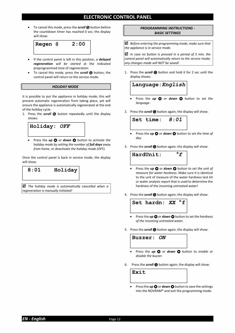
12. Press the scroll button again; the display will show:
• Press the up or down button to set the function of auxilliary contact 2:
Regen: aux. contact is powered during entire regeneration (does not include refill and brine preparation cycles!).
Chlor.Cell: aux. contact is powered at start of brine draw/slow rinse cycle. Press the scroll button again and press the up or down button to set the duration of activation of the chlorination cell.
Maintenance: aux. contact is powered when Maintenance Reminder is triggered.
Error: aux. contact is powered when timer failure occurs.
13. Press the scroll button again; the display will show:
• Press the up or down button to save the program into the NOVRAM® and exit the programming level.
Exit
Rsrv Variable
AUX2: Regen

ELECTRONIC CONTROL PANEL
Page 15 EN - English
only for PF-SOF1-ALT & PF-SOF1,5-ALT
The 2 Simplex systems, that make up a Duplex system, must be programmed individually; the program does NOT necessarily have to be the same on the 2 Simplex systems!
1. Press the scroll button and hold it for 6 sec until the
display shows: 2. Within 10 sec, press the up button; the display will
show:
• Press the up or down button to set the units of measure (Metric or US).
3. Press the scroll button again; the display will show:
• Press the up or down button to activate the maintenance reminder function by setting the maintenance interval, or deactivate the maintenance reminder function.
4. Press the scroll button again; the display will show:
• Press the up or down button to set the exchange capacity per litre of resin.
5. Press the scroll button again; the display will show:
• Press the up or down button to set the age correction factor (%/year) to compensate for capacity loss of the resin due to aging.
6. Press the scroll button again; the display will show:
• Press the up or down button to set the volume of resin.
7. Press the scroll button again; the display will show:
• Press the up or down button to set the number of days between regenerations.
8. Press the scroll button again; the display will show:
• Press the up or down button to set the length of the regeneration cycle.
• Press the scroll button again to advance to the next regeneration cycle.
Cycle 1 Backwash
Cycle 2 Brine draw/slow rinse
Cycle 3 Fast rinse/brine tank refill (PF-SOF1) Fast rinse (PF-SOF1,5)
Cycle 4 Brine tank refill (PF-SOF1,5)
9. Press the scroll button again; the display will show:
• Press the up or down button to set the function of auxilliary contact 2:
Regen: aux. contact is powered during entire regeneration (does not include refill and brine preparation cycles!).
Chlor.Cell: aux. contact is powered at start of brine draw/slow rinse cycle. Press the scroll button again and press the up or down button to set the duration of activation of the chlorination cell.
Maintenance: aux. contact is powered when Maintenance Reminder is triggered.
Error: aux. contact is powered when timer failure occurs.
10. Press the scroll button again; the display will show:
• Press the up or down button to save the program into the NOVRAM® and exit the programming level.
11. Repeat steps 1-10 for both Simplex systems.
Cycle 1: XX min
System Check
Resin:XXX liters
ExCap:5.5°f M3/L
Exit
Units:Metric
Age corr.: 2.0%
Override: 7 days
MaintInt: 24mths
AUX2: Regen

ELECTRONIC CONTROL PANEL
EN - English Page 16
only for PF-SOF1-PRL & PF-SOF1,5-PRL
The 2 Simplex systems, that make up a Duplex system, must be programmed individually; the program does NOT necessarily have to be the same on the 2 Simplex systems!
1. Press the scroll button and hold it for 6 sec until the
display shows: 2. Within 10 sec, press the up button; the display will
show:
• Press the up or down button to set the units of measure (Metric or US).
3. Press the scroll button again; the display will show:
• Press the up or down button to activate the maintenance reminder function by setting the maintenance interval, or deactivate the maintenance reminder function.
4. Press the scroll button again; the display will show:
• Press the up or down button to set the exchange capacity per litre of resin.
5. Press the scroll button again; the display will show:
• Press the up or down button to set the age correction factor (%/year) to compensate for capacity loss of the resin due to aging.
6. Press the scroll button again; the display will show:
• Press the up or down button to set the volume of resin.
7. Press the scroll button again; the display will show:
• Press the up or down button to set the number of days between regenerations.
8. Press the scroll button again; the display will show:
• Press the up or down button to set the length of the regeneration cycle.
• Press the scroll button again to advance to the next regeneration cycle.
Cycle 1 Backwash
Cycle 2 Brine draw/slow rinse
Cycle 3 Fast rinse/brine tank refill (PF-SOF1) Fast rinse (PF-SOF1,5)
Cycle 4 Brine tank refill (PF-SOF1,5)
9. Press the scroll button again; the display will show:
• Press the up or down button to set the regeneration mode:
Immediate: when the remaining capacity equals 0, an immediate regeneration is started. Note: Delayed manual regeneration is not available when this regeneration mode is selected.
Dlyd/Immd: when the remaining capacity equals the reserve capacity, a delayed regeneration at the programmed time of regeneration is started; however when the remaining capacity equals 0 before the programmed time of regeneration is reached, an immediate regeneration is started.
Delayed: when the remaining capacity equals the reserve capacity, a delayed regeneration at the programmed time of regeneration is started.
10. Press the scroll button again; the display will show
(only when the regeneration mode is set to ‘Delayed’ or ‘Dlyd/Immd’):
• Press the up or down button to set the time of regeneration.
11. Press the scroll button again; the display will show
(only when the regeneration mode is set to ‘Delayed’ or ‘Dlyd/Immd’):
• Press the up or down button to set the reserve capacity:
Variable: the reserve capacity is calculated automatically, based on the registered daily water usage.
Fxd: press the scroll button again and press the up or down button to set the reserve capacity to a fixed amount.
Regen:Immediate
Rsrv Variable
Regen @ 2:00
Cycle 1: XX min
System Check
Resin:XXX liters
ExCap:5.5°f M3/L
Units:Metric
Age corr.: 2.0%
Override: 7 days
MaintInt: 24mths
ELECTRONIC CONTROL PANEL
Page 17 EN - English
12. Press the scroll button again; the display will show:
• Press the up or down button to set the function of auxilliary contact 2:
Regen: aux. contact is powered during entire regeneration (does not include refill and brine preparation cycles!).
Chlor.Cell: aux. contact is powered at start of brine draw/slow rinse cycle. Press the scroll button again and press the up or down button to set the duration of activation of the chlorination cell.
Maintenance: aux. contact is powered when Maintenance Reminder is triggered.
Error: aux. contact is powered when timer failure occurs.
13. Press the scroll button again; the display will show:
• Press the up or down button to save the program into the NOVRAM® and exit the programming level.
14. Repeat steps 1-13 for both Simplex systems.
Exit
AUX2: Regen

MAINTENANCE
EN - English Page 18
RECOMMENDATION
Notwithstanding the reliability of the appliance, we strongly recommend to have it serviced and maintained on a regular basis by a competent and duly trained technician. He will be able to determine the appropriate maintenance interval for the appliance, depending on your specific application and the local operating conditions. The advantages of performing regular maintenance are:
• regular check of the local operating conditions (water quality, pressure, etc);
• regular control and adjustment of the settings of the appliance, to guarantee it operates at maximum efficiency;
• minimize the risk of unexpected break-down. Contact your dealer or installer for more information, or visit our website.
ROUTINE CHECKS
Regularly the user should perform a basic check to verify if the appliance is functioning correctly, on the basis of the following control points: 1. Check settings of electronic control panel. 2. Measure water hardness before/after appliance. 3. Check drain line from control valve; there shouldn’t be
any water flow (unless appliance is in regeneration). 4. Check drain line from brine tank overflow; there shouldn’t
be any water flow. 5. Check appliance and surrounding area; there shouldn’t be
any water leakages.
BYPASSING THE APPLIANCE
Occasionally it may be necessary to put the appliance hydraulically in bypass, i.e. to isolate it from the water distribution system; f.e.:
• in case of an urgent technical problem;
• when it is not necessary to supply treated water to the application.
WITH FACTORY BYPASS (optional) (only for PF-SOF1)
Picture 15.a
SERVICE POSITION = inlet valve to appliance is OPEN ❖ = outlet valve from appliance is OPEN
Picture 15.b
BYPASS POSITION = inlet valve to appliance is CLOSED ❖ = outlet valve from appliance is CLOSED
Picture 15.c
MAINTENANCE POSITION = inlet valve to appliance is OPEN ❖ = outlet valve from appliance is CLOSED
WATER CONDITIONER SALT
This appliance needs 'brine' for its periodic regenerations. This brine solution is made from water, that is automatically dosed in the brine tank by the control valve, and water conditioner salt. The user should make sure that the brine tank is always kept full of water conditioner salt. Therefore he should periodically check the salt level inside the brine tank and refill it if necessary. Simply lift the brine tank cover to check the salt level inside the brine tank. Ideally the level of water conditioner salt inside the brine tank is kept between 1/3 and 2/3. A lower level of water conditioner salt can cause insufficient brine saturation, resulting in a loss of softening capacity. A higher level of water conditioner salt can cause salt bridging (hard crust or salt bridges in the brine tank). When you suspect salt bridging:
• carefully pound on the outside of the brine tank to break loose the salt bridges;
• using a broom (or like blunt tool) carefully push the salt to break it apart;
• pour warm water over the top of the salt to dissolve it.
RESIN CLEANER
Other contaminants (f.e. iron) present in the feed water can cause the resin bed to foul up, resulting in a loss of softening capacity. An approved resin cleaner can be used periodically to thoroughly clean the resin bed.
SANITIZING THE APPLIANCE
This appliance is manufactured from premium quality material and assembled in safe conditions to assure it is clean and sanitary. If installed and serviced correctly, this appliance will not infect or contaminate your water supply. However, as in any 'device' plumbed-in in your water distribution system, a proliferation of bacteria is possible, especially in case of 'stagnant water'. Therefore this appliance is equipped with a 'days override' feature, that will automatically rinse the resin bed periodically, even in case of low or absence of water usage. If the power supply to the appliance is disconnected for a longer period of time, we recommend, when the power supply is re-established, to manually initiate a complete regeneration.
NORMALLY CLOSED SERVICE VALVES
(only for PF-SOF1-ALT & PF-SOF1,5-ALT)
Picture 16
= automatically operated = normally closed ❖ = manually operated = constantly open The Normally Closed Service Valve in the outlet of each Simplex system will only be opened when it is powered. To manually open the Normally Closed Service Valve (f.e. in case of a power failure), simply turn the white solenoid coil counter clockwise.
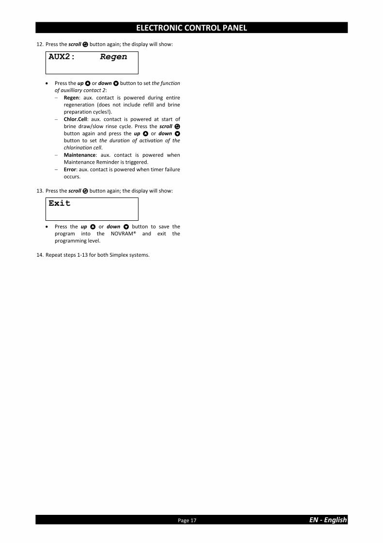
COMPOSITION OVERVIEW
Page 19 EN - English
Model Resin
volume PN
Control valve, incl. transformer, 1” BSP Male connections
InterConnect cable
Service Valve 1” BSP Female
Pressure tank, incl. distributor assy
Resin (25 ltr bag)
ltr model # # model # model # #
PF-
SOF1
-SIM
25 35810 2400VS/J4JB/PRL1 1 0 / 0 10x35 1 1
50 35811 2400VS/J1KD/PRL1 1 0 / 0 12x48 1 2
75 35812 2400VS/J1LD/PRL1 1 0 / 0 13x54 1 3
100 35813 2400VS/J2MD/PRL1 1 0 / 0 14x65 1 4
150 35814 2400VS/J2ND/PRL1 1 0 / 0 16x65 1 6
PF-
SOF1
-ALT
2 x 25 35815 2400VS/J4JB/ALT 2 1 NC (1) 2 10x35 2 2
2 x 50 35816 2400VS/J1KD/ALT 2 1 NC (1) 2 12x48 2 4
2 x 75 35817 2400VS/J1LD/ALT 2 1 NC (1) 2 13x54 2 6
2 x 100 35818 2400VS/J2MD/ALT 2 1 NC (1) 2 14x65 2 8
2 x 150 35819 2400VS/J2ND/ALT 2 1 NC (1) 2 16x65 2 12
PF-
SOF1
-PR
L
2 x 25 35820 2400VS/J4JB/PRL1 2 1 NO (2) 2 10x35 2 2
2 x 50 35821 2400VS/J1KD/PRL1 2 1 NO (2) 2 12x48 2 4
2 x 75 35822 2400VS/J1LD/PRL1 2 1 NO (2) 2 13x54 2 6
2 x 100 35823 2400VS/J2MD/PRL1 2 1 NO (2) 2 14x65 2 8
2 x 150 35824 2400VS/J2ND/PRL1 2 1 NO (2) 2 16x65 2 12
(1) NC = Normally Closed (2) NO = Normally Open
Model Resin
volume PN
Control valve, incl. transformer, flow meter, 1,5” BSP Male connections
InterConnect cable
Service Valve 1,5” BSP Female
Pressure tank, incl. distributor assy
Resin (25 ltr bag)
ltr model # # Model # model # #
PF-
SOF1
,5-S
IM
75 35825 EV1.5VS/J/5A/40/12 1 0 / 0 13x54 1 3
100 35826 EV1.5VS/J/5A/50/12 1 0 / 0 14x65 1 4
150 35827 EV1.5VS/J/5A/60/12 1 0 / 0 16x65 1 6
200 35828 EV1.5VS/J/5/80/20 1 0 / 0 18x65 1 8
250 35829 EV1.5VS/J/5/100/20 1 0 / 0 21x62 1 10
350 35830 EV1.5VS/J/6/150/20 1 0 / 0 24x72 1 14
500 35831 EV1.5VS/J/6/200/20 1 0 / 0 30x72 1 20
PF-
SOF1
,5-A
LT
2 x 75 35832 EV1.5VS/J/5A/40/12/ALT 2 1 NC (1) 2 13x54 2 6
2 x 100 35833 EV1.5VS/J/5A/50/12/ALT 2 1 NC (1) 2 14x65 2 8
2 x 150 35834 EV1.5VS/J/5A/60/12/ALT 2 1 NC (1) 2 16x65 2 12
2 x 200 35835 EV1.5VS/J/5/80/20/ALT 2 1 NC (1) 2 18x65 2 16
2 x 250 35836 EV1.5VS/J/5/100/20/ALT 2 1 NC (1) 2 21x62 2 20
2 x 350 35837 EV1.5VS/J/6/150/20/ALT 2 1 NC (1) 2 24x72 2 28
2 x 500 35838 EV1.5VS/J/6/200/20/ALT 2 1 NC (1) 2 30x72 2 40
PF-
SOF1
,5-P
RL
2 x 75 35839 EV1.5VS/J/5A/40/12 2 1 NO (2) 2 13x54 2 6
2 x 100 35840 EV1.5VS/J/5A/50/12 2 1 NO (2) 2 14x65 2 8
2 x 150 35841 EV1.5VS/J/5A/60/12 2 1 NO (2) 2 16x65 2 12
2 x 200 35842 EV1.5VS/J/5/80/20 2 1 NO (2) 2 18x65 2 16
2 x 250 35843 EV1.5VS/J/5/100/20 2 1 NO (2) 2 21x62 2 20
2 x 350 35844 EV1.5VS/J/6/150/20 2 1 NO (2) 2 24x72 2 28
2 x 500 35845 EV1.5VS/J/6/200/20 2 1 NO (2) 2 30x72 2 40
(1) NC = Normally Closed (2) NO = Normally Open
TECHNICAL DATA - PF-SOF1
Page 20
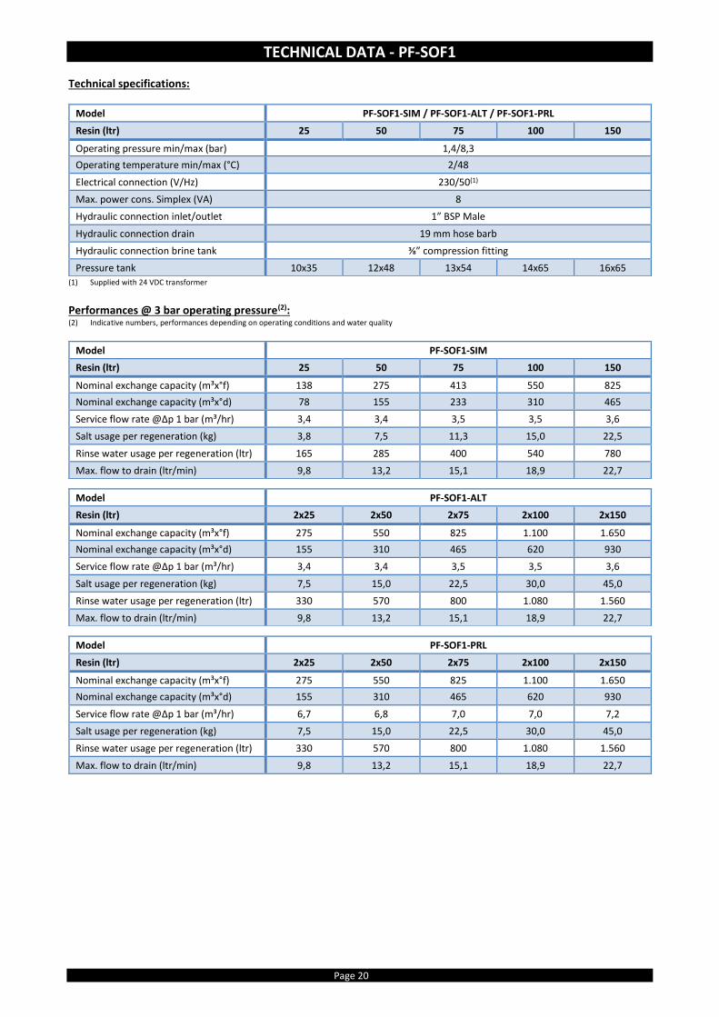
Technical specifications:
(1) Supplied with 24 VDC transformer
Performances @ 3 bar operating pressure(2): (2) Indicative numbers, performances depending on operating conditions and water quality
Model PF-SOF1-SIM / PF-SOF1-ALT / PF-SOF1-PRL
Resin (ltr) 25 50 75 100 150
Operating pressure min/max (bar) 1,4/8,3
Operating temperature min/max (°C) 2/48
Electrical connection (V/Hz) 230/50(1)
Max. power cons. Simplex (VA) 8
Hydraulic connection inlet/outlet 1” BSP Male
Hydraulic connection drain 19 mm hose barb
Hydraulic connection brine tank ⅜” compression fitting
Pressure tank 10x35 12x48 13x54 14x65 16x65
Model PF-SOF1-SIM
Resin (ltr) 25 50 75 100 150
Nominal exchange capacity (m³x°f) 138 275 413 550 825
Nominal exchange capacity (m³x°d) 78 155 233 310 465
Service flow rate @∆p 1 bar (m³/hr) 3,4 3,4 3,5 3,5 3,6
Salt usage per regeneration (kg) 3,8 7,5 11,3 15,0 22,5
Rinse water usage per regeneration (ltr) 165 285 400 540 780
Max. flow to drain (ltr/min) 9,8 13,2 15,1 18,9 22,7
Model PF-SOF1-ALT
Resin (ltr) 2x25 2x50 2x75 2x100 2x150
Nominal exchange capacity (m³x°f) 275 550 825 1.100 1.650
Nominal exchange capacity (m³x°d) 155 310 465 620 930
Service flow rate @∆p 1 bar (m³/hr) 3,4 3,4 3,5 3,5 3,6
Salt usage per regeneration (kg) 7,5 15,0 22,5 30,0 45,0
Rinse water usage per regeneration (ltr) 330 570 800 1.080 1.560
Max. flow to drain (ltr/min) 9,8 13,2 15,1 18,9 22,7
Model PF-SOF1-PRL
Resin (ltr) 2x25 2x50 2x75 2x100 2x150
Nominal exchange capacity (m³x°f) 275 550 825 1.100 1.650
Nominal exchange capacity (m³x°d) 155 310 465 620 930
Service flow rate @∆p 1 bar (m³/hr) 6,7 6,8 7,0 7,0 7,2
Salt usage per regeneration (kg) 7,5 15,0 22,5 30,0 45,0
Rinse water usage per regeneration (ltr) 330 570 800 1.080 1.560
Max. flow to drain (ltr/min) 9,8 13,2 15,1 18,9 22,7

TECHNICAL DATA - PF-SOF1
Page 21 EN - English
Dimensions:
Model PF-SOF1-SIM
Resin (ltr) 25 50 75 100 150
Width (mm) (W) 264 311 338 365 415
Depth (mm) (D) 282 311 338 365 415
Depth, incl. factory bypass (mm) (D) 371 376 389 403 428
Height (mm) (H) 1.059 ±10 1.394 ±10 1.560 ±10 1.836 ±10 1.833 ±10
Model PF-SOF1-ALT / PF-SOF1-PRL
Resin (ltr) 2x25 2x50 2x75 2x100 2x150
Width (mm) (W) (1) 613 707 761 815 915
Depth (mm) (D) 405 410 436 463 513
Height (mm) (H) 1.059 ±10 1.394 ±10 1.560 ±10 1.836 ±10 1.833 ±10 (1) Based on 85 mm spacing

TECHNICAL DATA - PF-SOF1,5
Page 22
Technical specifications:
(1) Supplied with 24 VAC transformer
Performances @ 3 bar operating pressure(2): (2) Indicative numbers, performances depending on operating conditions and water quality
Model PF-SOF1,5-SIM / PF-SOF1,5-ALT / PF-SOF1,5-PRL
Resin (ltr) 75 100 150 200 250 350 500
Operating pressure min/max (bar) 1,4/8,0
Operating temperature min/max (°C) 2/48
Electrical connection (V/Hz) 230/50(1)
Max. power cons. Simplex/Duplex (VA) 80/2x89
Hydraulic connection inlet/outlet 1,5” BSP Male/Female
Hydraulic connection drain 1” BSP Male
Hydraulic connection brine tank ½” compression fitting
Pressure tank 13x54 14x65 16x65 18x65 21x62 24x72 30x72
Model PF-SOF1,5-SIM
Resin (ltr) 75 100 150 200 250 350 500
Nominal exchange capacity (m³x°f) 413 550 825 1.100 1.375 1.925 2.750
Nominal exchange capacity (m³x°d) 233 310 465 620 775 1.085 1.550
Service flow rate @∆p 1 bar (m³/hr) 7,8 7,8 7,8 7,9 7,9 8,0 8,0
Salt usage per regeneration (kg) 11,3 15,0 22,5 30,0 37,5 52,5 75,0
Rinse water usage per regeneration (ltr) 469 578 838 1.148 1.435 2.140 3.030
Max. flow to drain (ltr/min) 15,2 19,0 22,7 30,3 37,9 56,8 75,7
Model PF-SOF1,5-ALT
Resin (ltr) 2x75 2x100 2x150 2x200 2x250 2x350 2x500
Nominal exchange capacity (m³x°f) 825 1.100 1.650 2.200 2.750 3.850 5.500
Nominal exchange capacity (m³x°d) 465 620 930 1.240 1.550 2.170 3.100
Service flow rate @∆p 1 bar (m³/hr) 7,8 7,8 7,8 7,9 7,9 8,0 8,0
Salt usage per regeneration (kg) 22,5 30,0 45,0 60,0 75,0 105,0 150,0
Rinse water usage per regeneration (ltr) 938 1.156 1.676 2.296 2.870 4.280 6.060
Max. flow to drain (ltr/min) 15,2 19,0 22,7 30,3 37,9 56,8 75,7
Model PF-SOF1,5-PRL
Resin (ltr) 2x75 2x100 2x150 2x200 2x250 2x350 2x500
Nominal exchange capacity (m³x°f) 825 1.100 1.650 2.200 2.750 3.850 5.500
Nominal exchange capacity (m³x°d) 465 620 930 1.240 1.550 2.170 3.100
Service flow rate @∆p 1 bar (m³/hr) 15,6 15,6 15,6 15,8 15,8 16,0 16,0
Salt usage per regeneration (kg) 22,5 30,0 45,0 60,0 75,0 105,0 150,0
Rinse water usage per regeneration (ltr) 938 1.156 1.676 2.296 2.870 4.280 6.060
Max. flow to drain (ltr/min) 15,2 19,0 22,7 30,3 37,9 56,8 75,7

TECHNICAL DATA - PF-SOF1,5
Page 23 EN - English
Dimensions:
Model PF-SOF1,5-SIM
Resin (ltr) 75 100 150 200 250 350 500
Width (mm) (W) 390 403 428 491 555 635 786
Depth (mm) (D) 575 575 575 595 627 667 786
Height (mm) (H) 1.623 1.904 1.901 1.952 1.951 2.148 2.066
Model
PF-SOF1,5-ALT / PF-SOF1,5-PRL
Resin (ltr) 2x75 2x100 2x150 2x200 2x250 2x350 2x500
Width (mm) (W) (1) 930 956 1.006 1.132 1.260 1.420 1.722
Depth (mm) (D) 690 690 690 706 738 778 850
Height (mm) (H) 1.623 1.904 1.901 1.952 1.951 2.148 2.066 (1) Based on 150 mm spacing

TECHNICAL DATA - PF-BTA
Page 24
Technical specifications:
Dimensions:
Model PF-BTA
Volume (ltr) 125 275 500 750
Diameter (mm) (D) 540 685 875 1.030
Height (mm) (H) 850 975 1.110 1.110
Height overflow (mm) (H1) 660 825 945 945
Max. salt storage capacity (kg) 100 200 475 700
Model PF-BTA
Volume (ltr) 125 275 500 750
Hydraulic connection brine valve interchangeable: ⅜” Quick-Fit & ½” compression fitting
Hydraulic connection overflow 19 mm hose barb

TABLE DES MATIÈRES & DONNÉES D’INSTALLATION
Page 25 FR - Français
Table des matières & Données d’installation .......................................................................... Page 25
Mesures de précaution & Consignes de sécurité .................................................................... Page 26
Conditions de fonctionnement & Exigences ............................................................................ Page 27
Assemblage .............................................................................................................................. Page 28
Installation ............................................................................................................................... Page 30
Mise en marche ........................................................................................................................ Page 32
Panneau de commande électronique ...................................................................................... Page 33
Entretien................................................................................................................................... Page 40
Liste de composition ................................................................................................................ Page 41
Données techniques - PF-SOF1 ................................................................................................ Page 42
Données techniques - PF-SOF1,5 ............................................................................................. Page 44
Données techniques - PF-BTA .................................................................................................. Page 46
Pour future référence, notez les données suivantes
DONNÉES D’INSTALLATION Numéro de série: ____________________________________________
Modèle: _______________________________________________________ Dureté d’eau-entrée: ________________________________________ Dureté d’eau-sortie: _________________________________________ Pression d’eau-entrée: ______________________________________
Date d’installation: __________________________________________
Nom société: _________________________________________________
Nom installeur: _______________________________________________ Numéro de tél.: ______________________________________________

MESURES DE PRÉCAUTION & CONSIGNES DE SÉCURITÉ
FR - Français Page 26
• Avant d’entamer l’installation de l’appareil, nous vous recommandons de lire et suivre attentivement les instructions dans ce manuel. Il contient des informations importantes concernant la sécurité, l’installation, l’usage et l’entretien du produit. L’appareil que vous avez reçu peut différer des photos/illustrations/descriptions dans ces Instructions.
• Ne pas suivre les instructions du manuel peut causer des blessures
personnelles et/ou endommager le produit. Seulement s’il est installé, mis en route et entretenu de manière correcte, l’appareil vous offrira de pleines années de service exempt de pannes.
• L’appareil est destiné à 'adoucir' l’eau, c’est à dire il enlèvera les minéraux
de dureté; il n’enlèvera pas nécessairement d’autres contaminants présents dans l’eau. L’appareil ne rendra pas de l’eau polluée pure ni potable!
• L’installation de l’appareil doit être effectuée par une personne
compétente, au courant des codes locaux en vigueur. Tous les raccordements hydrauliques et électriques doivent être réalisés en concordance aux codes locaux.
• Avant d’installer l’appareil, veuillez inspecter l’appareil pour contrôler s’il
n’y a pas de dommages visibles; n’installez pas l’appareil s’il est endommagé.
• Utiliser une charrette pour transporter l’appareil. Afin d’éviter tout
accident ou blessure, ne hisser pas l’appareil sur votre épaule. Ne mettez pas l’appareil sur son côté.
• Conservez ces Instructions dans un endroit sûr et veillez à informer de
nouveaux utilisateurs de son contenu.
• L’appareil est dessiné et fabriqué en concordance aux consignes de sécurité et régulations actuelles. Des réparations incorrectes peuvent mettre en péril le matériel de l’utilisateur, pour lequel le fabricant ne peut pas être rendu responsable. Pour cette raison toute réparation ne peut être effectuée que par un technicien compétent et formé pour ce produit.
• En respect de l’environnement, cet appareil devrait être recyclé en
concordance à la loi Déchets d’Equipements Électriques et Électroniques (DEEE). Vérifier les lois et codes nationaux/locaux pour le recyclage correct de cet appareil.

CONDITIONS DE FONCTIONNEMENT & EXIGENCES
Page 27 FR - Français
• PRESSION DE SERVICE MIN-MAX: 1,4-8,0 bar / 20-116 psi cet appareil est configuré pour fonctionner de manière optimale à
une pression de service de 3 bar (45 psi) ±½ bar (7 psi); une pression de service inférieure ou supérieure peut affecter les performances de manière négative!
contrôlez régulièrement la pression d’eau ; elle peut fluctuer considérablement selon l’heure du jour, le jour de la semaine ou même le saison de l’année.
prenez en considération que la pression d’eau pendant la nuit peut être considérablement plus élevée que la pression d’eau pendant la journée.
installez un réducteur de pression en amont de l’appareil si nécessaire.
installez un surpresseur, s’il est probable que la pression d’eau peut descendre en dessous du minimum.
• TEMPÉRATURE DE SERVICE MIN-MAX: 2-48 °C / 35-120 °F n’installez pas l’appareil dans un endroit où des températures élevées
(Ex: chaufferie non-ventilée) ou de gel peuvent se présenter.
l’appareil ne peut pas être exposé aux éléments extérieurs, comme la lumière directe du soleil ou précipitation atmosphérique.
n’installez pas l’appareil trop proche d’une chaudière; conservez au moins 3 m de conduite entre la sortie de l’appareil et la chaudière; une chaudière peut transmettre, à travers la conduite d’alimentation d’eau froide, de la chaleur dans la vanne de commande; installez toujours un clapet anti-retour à la sortie de l’appareil.
• ALIMENTATION ÉLECTRIQUE: l’appareil fonctionne uniquement en 24 V; utilisez l’appareil toujours
en combinaison avec le transformateur fourni.
en cas de dommages au câble d’alimentation du transformateur, débranchez immédiatement le transformateur de la prise de courant et remplacez le transformateur.
branchez le transformateur dans une prise de courant, installée dans un endroit sec, de la tension correcte et munie d’une protection adéquate contre toute surtension.

ASSEMBLAGE
FR - Français Page 28
VÉRIFICATION DU CONTENU
Les composants que vous avez reçu, peuvent différer des photos/illustrations dans ces Instructions!
Pour faciliter le transport et l’installation, la résine n’est PAS mise dans la bouteille à pression, mais fournie en sacs séparés de 25 ltr; elle doit être mise sur site, après mise en position de la bouteille à pression.
Vérifiez le contenue du système; reportez-vous à la Liste de Composants au dos de ces Instructions. Identifiez et étalez les différents composants pour faciliter l’assemblage.
SIMPLEX (PF-SOF1-SIM & PF-SOF1,5-SIM)
Un système Simplex system comprends 1 seule module d’adoucissement (bouteille à pression, résine, vanne de commande et accessoires).
En fonctionnement normal, le système Simplex délivre de l’eau adoucie. Dès que le système commence une régénération, il se met automatiquement en bypass d’eau dure, garantissant un approvisionnement ininterrompu d’eau non-traitée. Il est possible de convertir un système Simplex en système Duplex Alterné, par l’ajout d’un deuxième système Simplex.
DUPLEX ALTERNÉ (PF-SOF1-ALT & PF-SOF1,5-ALT)
Un système Duplex ALTERNÉ comprends 2 systèmes Simplex, qui: - sont installés hydrauliquement en parallèle; - sont interconnectés électroniquement au moyen d’un
câble InterConnect; - sont équipés d’une électrovanne Normalement Fermée
(i.e. Vanne de Service) sur la sortie de chaque système Simplex; cette Vanne de Service est pilotée par la commande électronique du système Simplex et est activée pendant le cycle de service afin d’ouvrir la sortie du système Simplex;
- partagent 1 bac à sel, qui contient 2 vannes à saumure. En fonctionnement normal, seulement 1 des 2 systèmes Simplex est en service, tandis que l’autre est en régénération ou ‘en veille’! Dès que le premier système Simplex commence une régénération, le second système se met en service, garantissant un approvisionnement ininterrompu d’eau traitée. Lors d’une panne de courant, les deux Vannes de Service seront désactivées, c'est-à-dire la sortie des deux systèmes Simplex sera fermée, coupant l’approvisionnement en eau (potentiellement de l’eau dure!) à l’application.
DUPLEX PARALLEL (PF-SOF1-PRL & PF-SOF1,5-PRL)
Un système Duplex PARALLEL comprends 2 systèmes Simplex, qui: - sont installés hydrauliquement en parallèle; - sont interconnectés électroniquement au moyen d’un
câble InterConnect;
- sont équipés d’une électrovanne Normalement Ouverte (i.e. Vanne de Service) sur la sortie de chaque système Simplex; cette Vanne de Service est pilotée par la commande électronique du système Simplex et est activée pendant toute la durée de la régénération, afin de fermer le 'bypass d’eau dure pendant la régénération' d’ la vanne de commande;
- partagent 1 bac à sel, qui contient 2 vannes à saumure. En fonctionnement normal, les 2 systèmes Simplex sont en service, doublant ainsi le débit de service! Lorsqu’un des systèmes Simplex se met en régénération, il communique immédiatement son état à l’autre système Simplex via le câble InterConnect, pour assurer que l’autre système Simplex reste en service, garantissant la fourniture ininterrompue d’eau traitée. Lors d’une panne de courant, les 2 Vannes de Service seront désactivées, c'est-à-dire la sortie des 2 systèmes Simplex sera ouverte, garantissant un approvisionnement ininterrompu d’eau. Pour l’assemblage correct, répétez les différentes phases d’assemblage, jusqu’à ce que les 2 systèmes Simplex soient assemblés et positionnés correctement. Pour des installations plus larges, avec une demande importante d’eau traitée, 2 ou plusieurs systèmes Duplex peuvent être installés en parallèle hydrauliquement, afin de doubler/tripler/... le débit de service et la capacité d’échange!
REMPLISSAGE DE LA RÉSINE
1. Placez la bouteille à pression sur l’emplacement
d’installation correcte; positionnez-le sur une surface égale et horizontale. Laissez suffisamment d’espace pour effectuer l’entretien.
2. Placez le tube de distribution verticale et centré dans la bouteille à pression; bouchez le bout du tube plongeur avec un morceau de ruban adhésif ou tissu, pour éviter que la résine entre dans le tube.
3. Mettez de l’eau dans la bouteille à pression jusqu’à une hauteur de ±30 cm du fond; cet eau protègera le fond de la bouteille à pression et le distributeur inférieur, durant le remplissage de la bouteille à pression.
4. Mettez un entonnoir sur l’ouverture de la bouteille à pression et versez la résine dans la bouteille à pression; vérifiez que le tube de distribution reste centré dans la bouteille à pression.
5. Rincez l’ouverture de la bouteille à pression afin d’enlever d’éventuelles billes de résine dans la section filetée.
6. Débouchez le bout du tube plongeur.
VANNE DE COMMANDE
uniquement pour PF-SOF1
1. Vérifiez que le joint dans l’adaptateur de tube plongeur et
le joint de la bouteille à pression (autour de la section filetée de la vanne de commande) se trouvent dans la position correcte.
2. Vissez la crépine supérieure sur la vanne de commande. 3. Lubrifiez la section filetée de la bouteille à pression, le
bout du tube plongeur et le joint de la bouteille à pression sur la vanne de commande; utilisez un lubrifiant à base de silicone.

ASSEMBLAGE
Page 29 FR - Français
4. Faites descendre la vanne de commande droit sur le tube plongeur, jusqu’à ce que le tube plongeur soit correctement inséré dans l’adaptateur de tube plongeur; ensuite poussez la vers le bas et vissez la sur la bouteille à pression.
uniquement pour PF-SOF1,5
Image 1
1. Sur le siège de vanne en laiton:
• vérifiez que le joint dans l’adaptateur de tube plongeur se trouve dans la position correcte;
• installez la crépine supérieure et fixez-la au moyen des 2 vis en acier inoxydable.
• installez le joint de la bouteille à pression dans la rainure dans le rebord autour de la section filetée.
2. Lubrifiez la section filetée de la bouteille de résine, le bout du tube plongeur et le joint de la bouteille sur le siège de vanne; utilisez un lubrifiant à base de silicone.
3. Faites descendre le siège de vanne droit sur le tube plongeur, jusqu’à ce que le tube plongeur soit correctement inséré dans l’adaptateur de tube plongeur dans le siège de vanne; ensuite poussez le vers le bas et vissez le sur la bouteille à pression.
4. Installez le joint du siège de vanne dans la rainure dans le siège de vanne.
5. Installez la vanne de commande sur le siège de vanne; attention à la broche d’alignement!
6. Fixez la vanne de commande au siège de vanne au moyen des 4 boulons en acier inoxydable; serrez bien.
ENSEMBLE BAC À SEL (PF-BTA) (optionnel)
Image 2&3
1. Placez le bac à sel sur la position d’installation correcte; positionnez-le sur une surface égale et horizontale. Laissez suffisamment d’espace pour aise d’entretien.
2. Insérez le polytube dans le raccord à saumure sur la vanne de commande (); serrez l’écrou.
3. Enlevez le couvercle du bac à sel. 4. Enlevez le couvercle de la cheminée à saumure. 5. Assurez-vous que le raccord coudé correct est installé sur
la vanne à saumure (⅜” pour PF-SOF1 ou ½” pour PF-SOF1,5); remplacez si nécessaire.
6. Acheminez le tube flexible de la vanne de commande par le trou dans le côté du bac à sel, à l’intérieur du bac à sel.
7. Uniquement pour PF-SOF1,5: insérez l’insert de renfort dans le bout du polytube ½”.
8. Insérez le tube flexible dans le raccord coudé sur la vanne à saumure ; veillez à l’enfoncer complètement.
9. Uniquement pour PF-SOF1,5: serrez l’écrou. 10. Mettez de l’eau dans le bac à sel jusqu’à une hauteur de
±10 cm du fond du bac à sel. 11. Mettez du sel dans le bac à sel. 12. Installez le couvercle sur la cheminée à saumure. 13. Installez le couvercle sur le bac à sel.
INSTALLATION
FR - Français Page 30
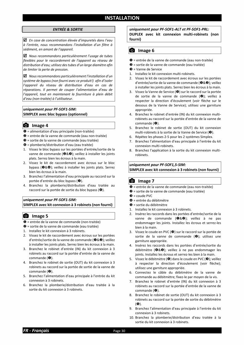
ENTRÉE & SORTIE
En case de concentration élevée d’impuretés dans l’eau à l’entrée, nous recommandons l’installation d’un filtre à sédiment, en amont de l’appareil.
Nous recommandons particulièrement l’usage de tubes flexibles pour le raccordement de l’appareil au réseau de distribution d’eau; utilisez des tubes d’un large diamètre afin de limiter la perte de pression.
Nous recommandons particulièrement l’installation d’un système de bypass (non fourni avec ce produit!) afin d’isoler l’appareil du réseau de distribution d’eau en cas de réparations. Il permet de couper l’alimentation d’eau de l’appareil, tout en maintenant la fourniture à plein débit d’eau (non-traitée) à l’utilisateur.
uniquement pour PF-SOF1-SIM: SIMPLEX avec bloc bypass (optionnel)
Image 4
= alimentation d’eau principale (non-traitée) ❖ = entrée de la vanne de commande (eau non-traitée) = sortie de la vanne de commande (eau traitée) = plomberie/distribution d’eau (eau traitée) 1. Vissez le bloc bypass sur les portées d’entrée/sortie de la
vanne de commande (❖&); veillez à installer les joints plats. Serrez bien les écrous à la main.
2. Vissez le kit de raccordement avec écrous sur le bloc bypass (&); veillez à installer les joints plats. Serrez bien les écrous à la main.
3. Branchez l’alimentation d’eau principale au raccord sur la portée d’entrée du bloc bypass ().
4. Branchez la plomberie/distribution d’eau traitée au raccord sur la portée de sortie du bloc bypass ().
uniquement pour PF-SOF1-SIM: SIMPLEX avec kit connexion à 3 robinets (non fourni)
Image 5
= entrée de la vanne de commande (non-traitée) ❖ = sortie de la vanne de commande (eau traitée) 1. Installez le kit connexion à 3 robinets. 2. Vissez le kit de raccordement avec écrous sur les portées
d’entrée/sortie de la vanne de commande (&❖); veillez à installer les joints plats. Serrez bien les écrous à la main.
3. Branchez le robinet d’entrée (IN) du kit connexion à 3 robinets au raccord sur la portée d’entrée de la vanne de commande ().
4. Branchez le robinet de sortie (OUT) du kit connexion à 3 robinets au raccord sur la portée de sortie de la vanne de commande (❖).
5. Branchez l’alimentation d’eau principale à l’entrée du kit connexion à 3 robinets.
6. Branchez la plomberie/distribution d’eau traitée à la sortie du kit connexion à 3 robinets.
uniquement pour PF-SOF1-ALT et PF-SOF1-PRL: DUPLEX avec kit connexion multi-robinets (non fourni)
Image 6
= entrée de la vanne de commande (eau non-traitée) ❖ = sortie de la vanne de commande (eau traitée) = Vanne de Service 1. Installez le kit connexion multi-robinets. 2. Vissez le kit de raccordement avec écrous sur les portées
d’entrée/sortie de la vanne de commande (&❖); veillez à installer les joints plats. Serrez bien les écrous à la main.
3. Vissez la Vanne de Service () sur le raccord sur la portée de sortie de la vanne de commande (❖); veillez à respecter la direction d’écoulement (voir flèche sur le dessous de la Vanne de Service); utilisez une garniture appropriée.
4. Branchez le robinet d’entrée (IN) du kit connexion multi-robinets au raccord sur la portée d’entrée de la vanne de commande ().
5. Branchez le robinet de sortie (OUT) du kit connexion multi-robinets à la sortie de la Vanne de Service ().
6. Répétez les phases 2-5 pour les 2 systèmes Simplex. 7. Branchez l’alimentation d’eau principale à l’entrée du kit
connexion multi-robinets. 8. Branchez l’application à la sortie du kit connexion multi-
robinets.
uniquement pour PF-SOF1,5-SIM: SIMPLEX avec kit connexion à 3 robinets (non fourni)
Image 7
= entrée de la vanne de commande (eau non-traitée) ❖ = sortie de la vanne de commande (eau traitée) = coude PVC = entrée du débitmètre = sortie du débitmètre 1. Installez le kit connexion à 3 robinets. 2. Insérez les raccords dans les portées d’entrée/sortie de la
vanne de commande (&❖); veillez à ne pas endommager les joints. Installez les écrous et serrez-les bien à la main.
3. Vissez le coude en PVC () sur le raccord sur la portée de sortie de la vanne de commande (❖); utilisez une garniture appropriée.
4. Insérez les raccords dans les portées d’entrée/sortie du débitmètre (&); veillez à ne pas endommager les joints. Installez les écrous et serrez-les bien à la main.
5. Vissez le débitmètre () dans le coude en PVC (); veillez à respecter la direction d’écoulement (voir flèche); utilisez une garniture appropriée.
6. Connectez le câble du débitmètre de la vanne de commande au débitmètre; fixez-le par moyen de la vis.
7. Branchez le robinet d’entrée (IN) du kit connexion à 3 robinets au raccord sur la portée d’entrée de la vanne de commande ().
8. Branchez le robinet de sortie (OUT) du kit connexion à 3 robinets au raccord sur la portée de sortie du débitmètre ().
9. Branchez l’alimentation d’eau principale à l’entrée du kit connexion à 3 robinets.
10. Branchez la plomberie/distribution d’eau traitée à la sortie du kit connexion à 3 robinets.

INSTALLATION
Page 31 FR - Français
uniquement pour PF-SOF1,5-ALT et PF-SOF1,5-PRL: DUPLEX avec kit connexion multi-robinets (non fourni)
Image 8
= entrée de la vanne de commande (eau non-traitée) ❖ = sortie de la vanne de commande (eau traitée) = coude PVC = entrée du débitmètre = sortie du débitmètre = Vanne de Service 1. Installez le kit connexion multi-robinets. 2. Insérez les raccords dans les portées d’entrée/sortie de la
vanne de commande (&❖); veillez à ne pas endommager les joints. Installez les écrous et serrez-les bien à la main.
3. Vissez le coude en PVC () sur le raccord sur la portée de sortie de la vanne de commande (❖); utilisez une garniture appropriée.
4. Insérez les raccords dans les portées d’entrée/sortie du débitmètre (&); veillez à ne pas endommager les joints. Installez les écrous et serrez-les bien à la main.
5. Vissez le débitmètre () dans le coude en PVC (); veillez à respecter la direction d’écoulement (voir flèche); utilisez une garniture appropriée.
6. Connectez le câble du débitmètre de la vanne de commande au débitmètre; fixez-le par moyen de la vis.
7. Vissez la Vanne de Service () sur le raccord sur la portée de sortie du débitmètre (); veillez à respecter la direction d’écoulement (voir flèche sur le dessous de la Vanne de Service); utilisez une garniture appropriée.
8. Branchez le robinet d’entrée (IN) du kit connexion multi-robinets au raccord sur la portée d’entrée de la vanne de commande ().
9. Branchez le robinet de sortie (OUT) du kit connexion multi-robinets à la sortie de la Vanne de Service ().
10. Répétez les phases 2-5 pour les 2 systèmes Simplex. 11. Branchez l’alimentation d’eau principale à l’entrée du kit
connexion multi-robinets. 12. Branchez l’application à la sortie du kit connexion multi-
robinets
ÉGOUT
Nous recommandons l’usage d’un tube rigide vertical avec siphon.
Afin de prévenir toute sorte de refoulement du réseau d’égout dans l’appareil, assurez toujours une rupture de charge suffisante entre le bout du tuyau ou tube de vidange et le réseau d’égout.
Utilisez toujours des tuyaux de rejet séparés pour la (les) vanne(s) de commande (évacuation d’eau de rinçage) et le(s) trop-plein(s) du bac à sel.
Acheminez les tuyaux de rejet à manière de minimiser la perte de pression; évitez des nœuds et élévations inutiles.
Assurez-vous que le réseau d’évacuation convient au débit de l’eau de rinçage de l’appareil.
uniquement pour PF-SOF1:
Image 9
1. Branchez le tuyau de 19 mm au coude d’égout de la vanne de commande (); fixez-le avec le collier.
2. Acheminez le tuyau vers le réseau d’égout et branchez-le, en assurant une rupture de charge suffisante entre le bout du tuyau et le réseau d’égout. Ce tuyau de vidange fonctionne sous pression, alors il peut être relevé plus haut que l’appareil.
3. Pour Duplex: répétez les phases 1-2 pour les 2 systèmes Simplex.
uniquement pour PF-SOF1,5:
Image 10
1. Branchez une tube au raccord d’égout 1” BSP male de la vanne de commande () ; utilisez une garniture appropriée.
2. Acheminez le tube vers le réseau d’égout et branchez-le, en assurant une rupture de charge suffisante entre le bout du tube et le réseau d’égout. Ce tube de vidange fonctionne sous pression, alors il peut être relevé plus haut que l’appareil.
3. Pour Duplex: répétez les phases 1-2 pour les 2 systèmes Simplex.
PF-BTA: ensemble bac à sel (optionnel)
1. Branchez le tuyau de 19 mm au trop plein du bac à sel;
fixez-le avec le collier. 2. Acheminez le tuyau vers le réseau d’égout et branchez-le,
en assurant une rupture de charge suffisante entre le bout du tuyau et le réseau d’égout. Ce tuyau de vidange ne fonctionne PAS sous pression, alors il ne peut PAS être relevé plus haut que le bac à sel.
VANNES DE SERVICE
(uniquement pour Duplex)
Image 11
1. Branchez la fiche DIN sur le câble de la Vanne de Service dans la prise DIN à l’arrière de la commande électronique de chaque vanne de commande ().

MISE EN MARCHE
FR - Français Page 32
ÉLECTRIQUE
1. Branchez le cordon d’alimentation de l’appareil àla sortie
du transformateur. 2. Branchez le transformateur dans une prise de courant.
MISE SOUS PRESSION 1. Assurez-vous que le système de bypass se trouve en
position ‘bypass’. 2. Assurez-vous que la (les) commande(s) électroniques de
l’appareil se trouve(nt) en mode service. 3. Ouvrez l’alimentation d’eau principale. 4. Ouvrez un robinet d’eau froide traitée en proximité de
l’appareil et laissez couler l’eau pendant quelques minutes pour purger l’air et pour rincer d’éventuelles impuretés résultant de l’installation; fermez le robinet.
5. Mettez sous pression gentiment l’appareil, en le mettant en service:
• fermez le robinet 'BYPASS'.
• ouvrez le robinet 'SORTIE'; ouvrez lentement le robinet 'ENTRÉE'.
6. Après 2-3 minutes, ouvrez un robinet d’eau froide traitée en proximité de l’appareil et laissez couler l’eau pendant quelques minutes pour purger l’air de l’installation et pour rincer la résine (il est normal que l’eau de rinçage est légèrement décolorée!); fermez le robinet.
7. Vérifiez que l’appareil et tous les raccordements hydrauliques ne fuient pas.
8. Pour Duplex: répétez les phases 5-7 pour les 2 systèmes Simplex.
PANNEAU DE COMMANDE ÉLECTRONIQUE
1. Programmez la commande électronique. 2. Pour Duplex: répétez la phase 1 pour les 2 systèmes
Simplex.
RÉGLAGE DURETÉ RÉSIDUELLE (uniquement pour PF-SOF1)
En pratique, la dureté résiduelle est influencée par la pression à l’entrée, le débit et la dureté de l’eau à l’entrée non-traitée. Lors du réglage de la dureté résiduelle, assurez-vous que ces conditions sont semblables aux conditions réelles de fonctionnement.
SUR VANNE DE COMMANDE
Image 12.a
1. Réglez la dureté résiduelle de l’eau qui sort de l’adoucisseur, par moyen de la vis de réglage, incorporée au niveau du côté droit de la vanne de commande:
• pour augmenter la dureté résiduelle: tournez la vis dans le sens antihoraire;
• pour diminuer la dureté résiduelle: tournez la vis dans le sens horaire.
2. Mesurez la dureté résiduelle de l’eau avec un kit de test de dureté d’eau; réajuster si nécessaire.
AVEC BLOC BYPASS (optionnel)
Image 12.b
1. Réglez la dureté résiduelle de l’eau qui sort de l’adoucisseur, par moyen de la vis de réglage, incorporée dans le robinet ‘sortie’ du bloc bypass:
• pour augmenter la dureté résiduelle: tournez la vis dans le sens antihoraire ;
• pour diminuer la dureté résiduelle: tournez la vis dans le sens horaire.
2. Mesurez la dureté résiduelle de l’eau avec un kit de test de dureté d’eau; réajuster si nécessaire.
LANCEZ UNE RÉGÉNÉRATION
1. Lancez manuellement une régénération, en appuyant sur
le bouton scroll ; l’écran affichera: 2. Laissez l’appareil dans cette position; le compteur à
rebours décomptera à 0 sec et démarrera une régénération; pour gagner du temps vous pouvez sauter, ou terminer prématurément, le deuxième cycle de la régénération en appuyant sur le bouton scroll une fois, dès que l’écran indique que le système est en deuxième position de régénération.
3. Pour Duplex: répétez les phases 1-2 pour tous les systèmes Simplex.
CÂBLE INTERCONNECT (uniquement pour Duplex)
Image 13
1. Connectez les vannes de commandes l’une à l’autre par moyen du câble InterConnect; branchez tout simplement les fiches DIN sur le câble InterConnect dans les prises femelles DIN à l’arrière de la commande électronique de chaque vanne de commande ().
ACTIVEZ LE MODE ALTERNÉ (uniquement pour Duplex Alterné)
1. Sur une des 2 vannes de commande, lancez
manuellement une régénération, en appuyant sur le bouton scroll ; l’écran affichera:
2. Laissez l’appareil dans cette position; le compteur à
rebours décomptera à 0 sec et démarrera une régénération. en Appuyant sur le bouton scroll une fois, dès que l’écran indique que le système est en deuxième position de régénération.
3. Appuyez sur le bouton scroll à quelques reprises, pour amener la vanne de commande à travers les cycles de régénération et pour la mettre en mode Standby, jusqu’à ce que l’écran affiche:
Régén en 10 sec
Régén en 10 sec
Stdby 1000 L –
Vol Tot:1234567L

PANNEAU DE COMMANDE ÉLECTRONIQUE
Page 33 FR - Français
Image 14
symbole bouton fonction
SCROLL pour avancer au paramètre
suivant
PLUS pour augmenter la valeur du
paramètre
MOINS pour diminuer la valeur du
paramètre
MISE SOUS TENSION
Après la mise sous tension, l’écran affichera la version de software installée pendant 5 sec.
PANNE DE COURANT
Lors d’une panne de courant, le programme sera conservé dans le NOVRAM® pour une durée indéfinie; en même temps un SuperCap (condensateur) maintiendra l’heure du jour correcte pendant une période de plusieurs heures; par conséquence il est possible que, lors d’une panne de courant de longue durée, l’heure du jour n’est pas maintenue; dans ce cas, lors du rétablissement du courant, l’indication de l’heure du jour clignotera, indiquant que l’heure du jour doit être réglée de nouveau. Quand la panne de courant se produit pendant l’exécution d’une régénération automatique, la vanne de commande restera dans sa dernière position; lors du rétablissement du courant, la vanne de commande retournera à la position de service, y restera 60 sec. et recommencera une régénération complète dès le début.
DÉFAUT DE COMMANDE
Lors d’un défaut de commande, l’écran affichera le message:
La sonnerie, si activée (voir Réglages de Base), emmetra des bips sonores en permanence. Si le problème n’est pas résolu après une mise hors/sous tension de l’appareil, il est nécessaire de faire appel à un technicien.
RAPPEL D’ENTRETIEN
Disponible uniquement si la fonction de rappel d’entretien a été activée et programmée par votre fournisseur!
Une fois l’intervalle d’entretien est atteint, ce qui se passera: 1. l’écran affichera en alternance le message:
2. la sonnerie, si activée (voir Réglages de Base), emmetra 3 bips sonores par heure.
Bien que l’appareil continue à fonctionner normalement, il est recommandé d’avoir un entretien préventif effectué par un professionnel.
MODE SERVICE
En mode service l’écran affiche:
• Simplex, Duplex Parallel: l’heure du jour et la capacité restante:
• Duplex Alterné: l’état du système (Service ou Standby) et la capacité restante:
MODE RÉGÉNÉRATION
En mode régénération l’écran affiche :
• Simplex, Duplex Parallel: la durée restante de la régénération et la durée restante du cycle actuel:
• Duplex Alterné: la durée restante de la régénération et la durée restante du cycle actuel:
Lorsque la régénération est terminée, le système reste en Standby, jusqu’à ce que l’autre système lance une régénération:
L’appareil peut être remis en mode service à tout temps en appuyant sur le bouton scroll ; de cette façon l’appareil est amené manuellement à travers les cycles de régénération.
RÉGÉNÉRATION MANUELLE
Il est possible de lancer manuellement une régénération immédiate ou une régénération retardée (à l’heure de régénération préprogrammée). 1. Appuyez sur le bouton scroll ; l’écran affichera:
• Si le panneau de commande est laissé dans cette position, le compteur à rebours décomptera à 0 sec et démarrera une régénération immédiate.
8:01 1000L –
Vol Tot:1234567L
Srvc 1000L –
Vol Tot:1234567L
Rgn:XXX CycY:ZZZ
Rgn:XXX CycY:ZZZ
Stdby 1000L –
Vol Tot:1234567L
Stdby 1000L -
8:01 1000L –
Demand Entretien
Service Requis
Régén en 10 sec

PANNEAU DE COMMANDE ÉLECTRONIQUE
FR - Français Page 34
• Pour annuler ce mode, appuyer sur le bouton scroll avant que le compteur à rebours ait atteint 0 sec; l’écran affichera:
• Si le panneau de commande est laissé dans cette position, une régénération retardée sera lancée à l’heure de régénération indiquée préprogrammée.
• Pour annuler ce mode, appuyer sur le bouton scroll
; le panneau de commande retournera au mode de service.
MODE VACANCES
Il est possible de mettre l’appareil en mode de vacances; ceci empêchera qu’une régénération automatique aurait lieu, mais veillera à ce que l’appareil est automatiquement régénéré à la fin du cycle de vacances. 1. Appuyez sur le bouton scroll à quelques reprises
jusqu’à ce que l’écran affiche:
• Appuyez sur le bouton plus ou moins pour activer le mode de vacances en saisissant le nombre de jours entiers loin de la maison, ou désactivater le mode vacances (OFF).
Une fois le panneau de commande est de retour en mode service, l’écran affichera:
Le mode de vacances est automatiquement annulé lorsqu’une régénération est lancée manuellement!
INSTRUCTIONS DE PROGRAMMATION - RÉGLAGES DE BASE
Avant d’accéder au mode de programmation, assurez-vous que l’appareil se trouve en mode service.
En cas aucun bouton n’est appuyé dans une période de 5 min, le panneau de commande retournera automatiquement au mode de service; les modifications apportées ne seront PAS sauvegardées!
1. Appuyez sur le bouton scroll et maintenez-le enfoncé
pendant 2 sec jusqu’à ce que l’écran affiche:
• Appuyez sur le bouton plus ou moins pour régler le langage.
2. Appuyez de nouveau sur le bouton scroll ; l’écran
affichera:
• Appuyez sur le bouton plus ou moins pour régler l’heure du jour.
3. Appuyez de nouveau sur le bouton scroll ; l’écran
affichera:
• Appuyez sur le bouton plus ou moins pour régler l’unité de mesure de la dureté d’eau. Assurez-vous qu’elle est identique à l’unité de mesure du kit de teste de dureté d’eau ou du rapport d’analyse d’eau utilisé pour la détermination de la dureté de l’eau à l’entrée non-traitée !
4. Appuyez de nouveau sur le bouton scroll ; l’écran
affichera:
• Appuyez sur le bouton plus ou moins pour régler la dureté de l’eau à l’entrée non-traitée.
5. Appuyez de nouveau sur le bouton scroll ; l’écran
affichera:
• Appuyez sur le bouton plus ou moins pour activer ou désactivater la sonnerie.
Vacances:OFF
8:01 Vacances
Régén à 2:00
Langage:Francais
Horloge: 8:01
Dureté: XX °f
UnitéDur: °f
Sonnerie: ON

PANNEAU DE COMMANDE ÉLECTRONIQUE
Page 35 FR - Français
6. Appuyez de nouveau sur le bouton scroll ; l’écran affichera:
• Appuyez sur le bouton plus ou moins pour sauvegarder les réglages dans le NOVRAM® et quitter le mode de programmation.
INSTRUCTIONS DE PROGRAMMATION - PARAMÈTRES DE CONFIGURATION
Avant d’accéder au mode de programmation, assurez-vous que l’appareil se trouve en mode service.
Tous les paramètres de configuration de cet appareil ont été préréglés à l’usine, afin d’offrir des performances optimales dans un large éventail d’applications et situations. Pourtant, il pourrait être nécessaire ou souhaité de changer ces paramètres, afin d’optimiser encore plus les performances de l’appareil ou de l’adapter aux exigences spécifiques de l’installation.
En cas aucun bouton n’est appuyé dans une période de 5 min, le panneau de commande retournera automatiquement au mode de service; les modifications apportées ne seront PAS sauvegardées !
uniquement pour PF-SOF1-SIM & PF-SOF1,5-SIM
1. Appuyez sur le bouton scroll et maintenez-le enfoncé
pendant 6 sec jusqu’à ce que l’écran affiche: 2. Avant 10 sec, appuyez sur le bouton plus ; l’écran
affichera:
• Appuyez sur le bouton plus ou moins pour régler les unités de mesure (Metrique ou English-US).
3. Appuyez de nouveau sur le bouton scroll ; l’écran
affichera:
• Appuyez sur le bouton plus ou moins pour activer la fonction de rappel de maintenance en réglant l’intervalle de maintenance, ou désactiver la fonction de rappel de maintenance.
4. Appuyez de nouveau sur le bouton scroll ; l’écran
affichera:
• Appuyez sur le bouton plus ou moins pour régler la capacité d’échange par litre de résine.
5. Appuyez de nouveau sur le bouton scroll ; l’écran affichera:
• Appuyez sur le bouton plus ou moins pour régler le facteur de correction d’âge (%/an) pour compenser la perte de capacité liée aux vieillissement de la résine.
Contrôle Système
CapEch:5.5°f M3
Entretien:24mois
Corr Capa: 2.0%
Unité:Metrique
Quitter

PANNEAU DE COMMANDE ÉLECTRONIQUE
FR - Français Page 36
6. Appuyez de nouveau sur le bouton scroll ; l’écran affichera:
• Appuyez sur le bouton plus ou moins pour régler le volume de résine.
7. Appuyez de nouveau sur le bouton scroll ; l’écran
affichera:
• Appuyez sur le bouton plus ou moins pour régler le nombre de jours entre régénérations.
8. Appuyez de nouveau sur le bouton scroll ; l’écran
affichera:
• Appuyez sur le bouton plus ou moins pour régler la durée du cycle de régénération.
• Appuyez de nouveau sur le bouton scroll pour avancer au cycle de régénération suivant.
Cycle 1 Détassage
Cycle 2 Saumurage/rinçage lent
Cycle 3 Rinçage rapide/renvoi d’eau (PF-SOF1) Rinçage rapide (PF-SOF1,5)
Cycle 4 Renvoi d’eau (PF-SOF1,5)
9. Appuyez de nouveau sur le bouton scroll ; l’écran
affichera:
• Appuyez sur le bouton plus ou moins pour régler la mode de régénération:
Retard/Imm: lorsque la capacité restante égalise la capacité de réserve, une régénération retardée à l’heure de régénération préprogrammée sera lancée; cependant, lorsque la capacité restante égalise 0 avant l’heure de régénération préprogrammée soit atteinte, une régénération immédiate est lancée.
Immédiate: lorsque la capacité restante égalise 0 une régénération immédiate est lancée. Remarque: la régénération manuelle retardée n'est pas disponible lorsque ce mode de régénération est sélectionné.
Retardée: lorsque la capacité restante égalise la capacité de réserve, une régénération retardée à l’heure de régénération préprogrammée sera lancée.
10. Appuyez de nouveau sur le bouton scroll ; l’écran affichera (uniquement si mode de régénération est réglé sur ‘Retardé’ ou ‘Retard/Imm’):
• Appuyez sur le bouton plus ou moins pour régler l’heure de régénération.
11. Appuyez de nouveau sur le bouton scroll ; l’écran
affichera (uniquement si mode de régénération est réglé sur ‘Retardé’ ou ‘Retard/Imm’):
• Appuyez sur le bouton plus ou moins pour régler la capacité de réserve:
Variable: la capacité de réserve est calculée automatiquement, à base de la consommation d’eau journalière enregistrée.
Fix: appuyez sur le bouton plus ou moins pour régler la cap. de réserve sur une valeur fixe.
12. Appuyez de nouveau sur le bouton scroll ; l’écran
affichera:
• Appuyez sur le bouton plus ou moins pour sélectionner la fonction du contact auxiliaire 2:
Regen: le contact auxiliaire est alimenté durant toute la régénération (pas lors des cycles de remplissage ni de préparation de saumure !)
Chlor.cell: le contact auxiliaire est alimenté au démarrage du cycle d’aspiration saumure/rinçage lent. Appuyez de nouveau sur le bouton scroll et ensuite utilisez les boutons plus ou moins pour régler pour régler la durée de l’activation du chlorinateur.
Maintenance: le contact auxiliaire est alimenté lorsque le Message de maintenance se déclenche.
Error: le contact auxiliaire est alimenté lorqu’une perte de l’heure se produit.
13. Appuyez de nouveau sur le bouton scroll ; l’écran
affichera:
• Appuyez sur le bouton plus ou moins pour sauvegarder le programme dans le NOVRAM® et quitter le niveau de programmation.
Cycle 1: XX min
Régén à 2:00 Résine:XXX ltr
Régén:Retard/Imm
Rsrv Variable
Forcage: 7 jours
Quitter
AUX2: Régén

PANNEAU DE COMMANDE ÉLECTRONIQUE
Page 37 FR - Français
uniquement pour PF-SOF1-ALT & PF-SOF1,5-ALT
Les 2 systèmes Simplex, qui forment un système Duplex, doivent être programmé individuellement; le programme ne doit PAS nécessairement être le même sur les 2 systèmes Simplex!
1. Appuyez sur le bouton scroll et maintenez-le enfoncé
pendant 6 sec jusqu’à ce que l’écran affiche: 2. Avant 10 sec, appuyez sur le bouton plus ; l’écran
affichera:
• Appuyez sur le bouton plus ou moins pour régler les unités de mesure (Metrique ou English-US).
3. Appuyez de nouveau sur le bouton scroll ; l’écran
affichera:
• Appuyez sur le bouton plus ou moins pour activer la fonction de rappel de maintenance en réglant l’intervalle de maintenance, ou désactiver la fonction de rappel de maintenance.
4. Appuyez de nouveau sur le bouton scroll ; l’écran
affichera:
• Appuyez sur le bouton plus ou moins pour régler la capacité d’échange par litre de résine.
5. Appuyez de nouveau sur le bouton scroll ; l’écran affichera:
• Appuyez sur le bouton plus ou moins pour régler le facteur de correction d’âge (%/an) pour compenser la perte de capacité liée aux vieillissement de la résine.
6. Appuyez de nouveau sur le bouton scroll ; l’écran affichera:
• Appuyez sur le bouton plus ou moins pour régler le volume de résine.
7. Appuyez de nouveau sur le bouton scroll ; l’écran affichera:
• Appuyez sur le bouton plus ou moins pour régler le nombre de jours entre régénérations.
8. Appuyez de nouveau sur le bouton scroll ; l’écran
affichera:
• Appuyez sur le bouton plus ou moins pour régler la durée du cycle de régénération.
• Appuyez de nouveau sur le bouton scroll pour avancer au cycle de régénération suivant.
Cycle 1 Détassage
Cycle 2 Saumurage/rinçage lent
Cycle 3 Rinçage rapide/renvoi d’eau (PF-SOF1) Rinçage rapide (PF-SOF1,5)
Cycle 4 Renvoi d’eau (PF-SOF1,5)
9. Appuyez de nouveau sur le bouton scroll ; l’écran
affichera:
• Appuyez sur le bouton plus ou moins pour sélectionner la fonction du contact auxiliaire 2:
Regen: le contact auxiliaire est alimenté durant toute la régénération (pas lors des cycles de remplissage ni de préparation de saumure !)
Chlor.cell: le contact auxiliaire est alimenté au démarrage du cycle d’aspiration saumure/rinçage lent. Appuyez de nouveau sur le bouton scroll et ensuite utilisez les boutons plus ou moins pour régler pour régler la durée de l’activation du chlorinateur.
Maintenance: le contact auxiliaire est alimenté lorsque le Message de maintenance se déclenche.
Error: le contact auxiliaire est alimenté lorqu’une perte de l’heure se produit.
10. Appuyez de nouveau sur le bouton scroll ; l’écran
affichera:
• Appuyez sur le bouton plus ou moins pour sauvegarder le programme dans le NOVRAM® et quitter le niveau de programmation.
11. Répétez les phases 1-10 pour les 2 systèmes Simplex.
Quitter
Cycle 1: XX min
Contrôle Système
Résine:XXX ltr
CapEch:5.5°f M3
Forcage: 7 jours
Entretien:24mois
Corr Capa: 2.0%
Unité:Metrique
AUX2: Régén

PANNEAU DE COMMANDE ÉLECTRONIQUE
FR - Français Page 38
uniquement pour PF-SOF1-PRL & PF-SOF1,5-PRL
Les 2 systèmes Simplex, qui forment un système Duplex, doivent être programmé individuellement; le programme ne doit PAS nécessairement être le même sur les 2 systèmes Simplex!
1. Appuyez sur le bouton scroll et maintenez-le enfoncé
pendant 6 sec jusqu’à ce que l’écran affiche: 2. Avant 10 sec, appuyez sur le bouton plus ; l’écran
affichera:
• Appuyez sur le bouton plus ou moins pour régler les unités de mesure (Metrique ou English-US).
3. Appuyez de nouveau sur le bouton scroll ; l’écran
affichera:
• Appuyez sur le bouton plus ou moins pour activer la fonction de rappel de maintenance en réglant l’intervalle de maintenance, ou désactiver la fonction de rappel de maintenance.
4. Appuyez de nouveau sur le bouton scroll ; l’écran
affichera:
• Appuyez sur le bouton plus ou moins pour régler la capacité d’échange par litre de résine.
5. Appuyez de nouveau sur le bouton scroll ; l’écran affichera:
• Appuyez sur le bouton plus ou moins pour régler le facteur de correction d’âge (%/an) pour compenser la perte de capacité liée aux vieillissement de la résine.
6. Appuyez de nouveau sur le bouton scroll ; l’écran affichera:
• Appuyez sur le bouton plus ou moins pour régler le volume de résine.
7. Appuyez de nouveau sur le bouton scroll ; l’écran affichera:
• Appuyez sur le bouton plus ou moins pour régler le nombre de jours entre régénérations.
8. Appuyez de nouveau sur le bouton scroll ; l’écran
affichera:
• Appuyez sur le bouton plus ou moins pour régler la durée du cycle de régénération.
• Appuyez de nouveau sur le bouton scroll pour avancer au cycle de régénération suivant.
Cycle 1 Détassage
Cycle 2 Saumurage/rinçage lent
Cycle 3 Rinçage rapide/renvoi d’eau (PF-SOF1) Rinçage rapide (PF-SOF1,5)
Cycle 4 Renvoi d’eau (PF-SOF1,5)
9. Appuyez de nouveau sur le bouton scroll ; l’écran
affichera:
• Appuyez sur le bouton plus ou moins pour régler la mode de régénération:
Immédiate: lorsque la capacité restante égalise 0 une régénération immédiate est lancée. Remarque: la régénération manuelle retardée n'est pas disponible lorsque ce mode de régénération est sélectionné.
Retard/Imm: lorsque la capacité restante égalise la capacité de réserve, une régénération retardée à l’heure de régénération préprogrammée sera lancée; cependant, lorsque la capacité restante égalise 0 avant l’heure de régénération préprogrammée soit atteinte, une régénération immédiate est lancée.
Retardée: lorsque la capacité restante égalise la capacité de réserve, une régénération retardée à l’heure de régénération préprogrammée sera lancée.
10. Appuyez de nouveau sur le bouton scroll ; l’écran
affichera (uniquement si mode de régénération est réglé sur ‘Retardé’ ou ‘Retard/Imm’):
• Appuyez sur le bouton plus ou moins pour régler l’heure de régénération.
Régén @ 2:00
Régén:Immédiate
Cycle 1: XX min
Contrôle Système
Résine:XXX ltr
CapEch:5.5°f M3
Forcage: 7 jours
Entretien:24mois
Corr Capa: 2.0%
Unité:Metrique
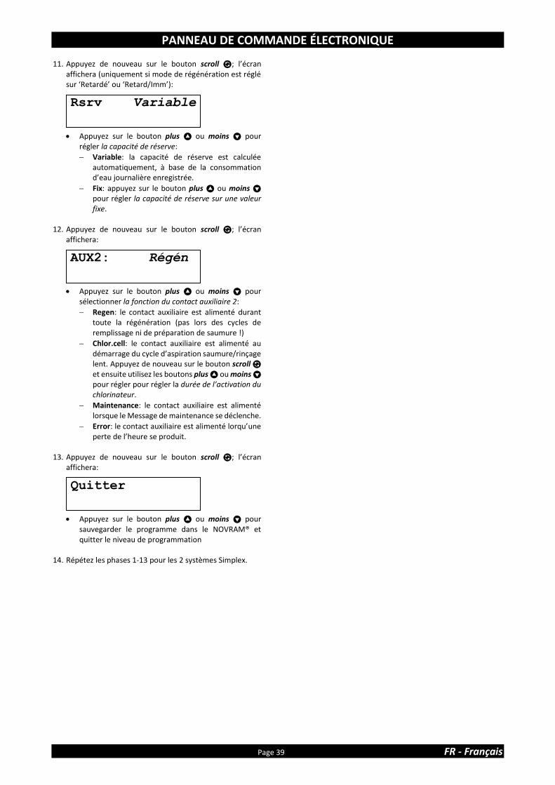
PANNEAU DE COMMANDE ÉLECTRONIQUE
Page 39 FR - Français
11. Appuyez de nouveau sur le bouton scroll ; l’écran affichera (uniquement si mode de régénération est réglé sur ‘Retardé’ ou ‘Retard/Imm’):
• Appuyez sur le bouton plus ou moins pour régler la capacité de réserve:
Variable: la capacité de réserve est calculée automatiquement, à base de la consommation d’eau journalière enregistrée.
Fix: appuyez sur le bouton plus ou moins pour régler la capacité de réserve sur une valeur fixe.
12. Appuyez de nouveau sur le bouton scroll ; l’écran
affichera:
• Appuyez sur le bouton plus ou moins pour sélectionner la fonction du contact auxiliaire 2:
Regen: le contact auxiliaire est alimenté durant toute la régénération (pas lors des cycles de remplissage ni de préparation de saumure !)
Chlor.cell: le contact auxiliaire est alimenté au démarrage du cycle d’aspiration saumure/rinçage lent. Appuyez de nouveau sur le bouton scroll et ensuite utilisez les boutons plus ou moins pour régler pour régler la durée de l’activation du chlorinateur.
Maintenance: le contact auxiliaire est alimenté lorsque le Message de maintenance se déclenche.
Error: le contact auxiliaire est alimenté lorqu’une perte de l’heure se produit.
13. Appuyez de nouveau sur le bouton scroll ; l’écran
affichera:
• Appuyez sur le bouton plus ou moins pour sauvegarder le programme dans le NOVRAM® et quitter le niveau de programmation
14. Répétez les phases 1-13 pour les 2 systèmes Simplex.
Rsrv Variable
Quitter
AUX2: Régén
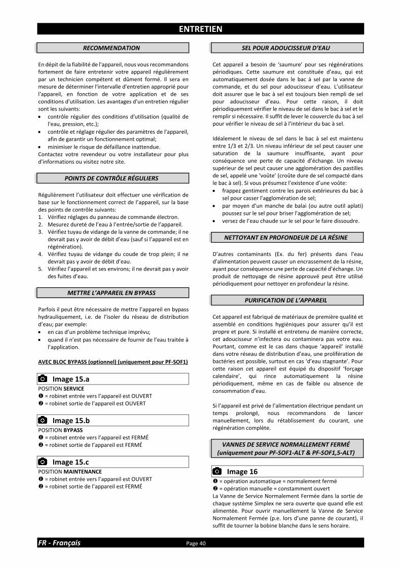
ENTRETIEN
FR - Français Page 40
RECOMMENDATION
En dépit de la fiabilité de l'appareil, nous vous recommandons fortement de faire entretenir votre appareil régulièrement par un technicien compétent et dûment formé. Il sera en mesure de déterminer l'intervalle d'entretien approprié pour l'appareil, en fonction de votre application et de ses conditions d'utilisation. Les avantages d'un entretien régulier sont les suivants:
• contrôle régulier des conditions d'utilisation (qualité de l'eau, pression, etc.);
• contrôle et réglage régulier des paramètres de l'appareil, afin de garantir un fonctionnement optimal;
• minimiser le risque de défaillance inattendue. Contactez votre revendeur ou votre installateur pour plus d'informations ou visitez notre site.
POINTS DE CONTRÔLE RÉGULIERS
Régulièrement l’utilisateur doit effectuer une vérification de base sur le fonctionnement correct de l’appareil, sur la base des points de contrôle suivants: 1. Vérifiez réglages du panneau de commande électron. 2. Mesurez dureté de l’eau à l’entrée/sortie de l’appareil. 3. Vérifiez tuyau de vidange de la vanne de commande; il ne
devrait pas y avoir de débit d’eau (sauf si l’appareil est en régénération).
4. Vérifiez tuyau de vidange du coude de trop plein; il ne devrait pas y avoir de débit d’eau.
5. Vérifiez l’appareil et ses environs; il ne devrait pas y avoir des fuites d’eau.
METTRE L’APPAREIL EN BYPASS
Parfois il peut être nécessaire de mettre l’appareil en bypass hydrauliquement, i.e. de l’isoler du réseau de distribution d’eau; par exemple:
• en cas d’un problème technique imprévu;
• quand il n’est pas nécessaire de fournir de l’eau traitée à l’application.
AVEC BLOC BYPASS (optionnel) (uniquement pour PF-SOF1)
Image 15.a
POSITION SERVICE = robinet entrée vers l’appareil est OUVERT ❖ = robinet sortie de l’appareil est OUVERT
Image 15.b
POSITION BYPASS = robinet entrée vers l’appareil est FERMÉ ❖ = robinet sortie de l’appareil est FERMÉ
Image 15.c
POSITION MAINTENANCE = robinet entrée vers l’appareil est OUVERT ❖ = robinet sortie de l’appareil est FERMÉ
SEL POUR ADOUCISSEUR D’EAU
Cet appareil a besoin de ‘saumure’ pour ses régénérations périodiques. Cette saumure est constituée d’eau, qui est automatiquement dosée dans le bac à sel par la vanne de commande, et du sel pour adoucisseur d’eau. L’utilisateur doit assurer que le bac à sel est toujours bien rempli de sel pour adoucisseur d’eau. Pour cette raison, il doit périodiquement vérifier le niveau de sel dans le bac à sel et le remplir si nécessaire. Il suffit de lever le couvercle du bac à sel pour vérifier le niveau de sel à l’intérieur du bac à sel. Idéalement le niveau de sel dans le bac à sel est maintenu entre 1/3 et 2/3. Un niveau inférieur de sel peut causer une saturation de la saumure insuffisante, ayant pour conséquence une perte de capacité d’échange. Un niveau supérieur de sel peut causer une agglomération des pastilles de sel, appelé une ‘voûte’ (croûte dure de sel compacté dans le bac à sel). Si vous présumez l’existence d’une voûte:
• frappez gentiment contre les parois extérieures du bac à sel pour casser l'agglomération de sel;
• par moyen d’un manche de balai (ou autre outil aplati) poussez sur le sel pour briser l'agglomération de sel;
• versez de l’eau chaude sur le sel pour le faire dissoudre.
NETTOYANT EN PROFONDEUR DE LA RÉSINE
D’autres contaminants (Ex. du fer) présents dans l’eau d’alimentation peuvent causer un encrassement de la résine, ayant pour conséquence une perte de capacité d’échange. Un produit de nettoyage de résine approuvé peut être utilisé périodiquement pour nettoyer en profondeur la résine.
PURIFICATION DE L’APPAREIL
Cet appareil est fabriqué de matériaux de première qualité et assemblé en conditions hygiéniques pour assurer qu’il est propre et pure. Si installé et entretenu de manière correcte, cet adoucisseur n’infectera ou contaminera pas votre eau. Pourtant, comme est le cas dans chaque ‘appareil’ installé dans votre réseau de distribution d’eau, une prolifération de bactéries est possible, surtout en cas ‘d’eau stagnante’. Pour cette raison cet appareil est équipé du dispositif ‘forçage calendaire’, qui rince automatiquement la résine périodiquement, même en cas de faible ou absence de consommation d’eau. Si l’appareil est privé de l’alimentation électrique pendant un temps prolongé, nous recommandons de lancer manuellement, lors du rétablissement du courant, une régénération complète.
VANNES DE SERVICE NORMALLEMENT FERMÉ (uniquement pour PF-SOF1-ALT & PF-SOF1,5-ALT)
Image 16
= opération automatique = normalement fermé ❖ = opération manuelle = constamment ouvert La Vanne de Service Normalement Fermée dans la sortie de chaque système Simplex ne sera ouverte que quand elle est alimentée. Pour ouvrir manuellement la Vanne de Service Normalement Fermée (p.e. lors d’une panne de courant), il suffit de tourner la bobine blanche dans le sens horaire.
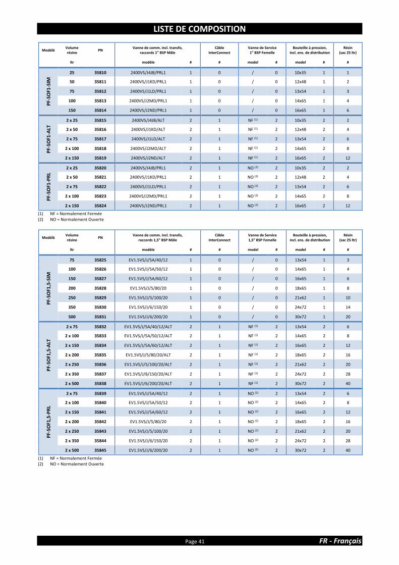
LISTE DE COMPOSITION
Page 41 FR - Français
Modélè Volume résine
PN Vanne de comm. incl. transfo,
raccords 1” BSP Mâle Câble
InterConnect Vanne de Service 1” BSP Femelle
Bouteille à pression, incl. ens. de distribution
Résin (sac 25 ltr)
ltr modèle # # model # model # #
PF-
SOF1
-SIM
25 35810 2400VS/J4JB/PRL1 1 0 / 0 10x35 1 1
50 35811 2400VS/J1KD/PRL1 1 0 / 0 12x48 1 2
75 35812 2400VS/J1LD/PRL1 1 0 / 0 13x54 1 3
100 35813 2400VS/J2MD/PRL1 1 0 / 0 14x65 1 4
150 35814 2400VS/J2ND/PRL1 1 0 / 0 16x65 1 6
PF-
SOF1
-ALT
2 x 25 35815 2400VS/J4JB/ALT 2 1 NF (1) 2 10x35 2 2
2 x 50 35816 2400VS/J1KD/ALT 2 1 NF (1) 2 12x48 2 4
2 x 75 35817 2400VS/J1LD/ALT 2 1 NF (1) 2 13x54 2 6
2 x 100 35818 2400VS/J2MD/ALT 2 1 NF (1) 2 14x65 2 8
2 x 150 35819 2400VS/J2ND/ALT 2 1 NF (1) 2 16x65 2 12
PF-
SOF1
-PR
L
2 x 25 35820 2400VS/J4JB/PRL1 2 1 NO (2) 2 10x35 2 2
2 x 50 35821 2400VS/J1KD/PRL1 2 1 NO (2) 2 12x48 2 4
2 x 75 35822 2400VS/J1LD/PRL1 2 1 NO (2) 2 13x54 2 6
2 x 100 35823 2400VS/J2MD/PRL1 2 1 NO (2) 2 14x65 2 8
2 x 150 35824 2400VS/J2ND/PRL1 2 1 NO (2) 2 16x65 2 12
(1) NF = Normalement Fermée (2) NO = Normalement Ouverte
Modélè Volume résine
PN Vanne de comm. incl. transfo,
raccords 1,5” BSP Mâle Câble
InterConnect Vanne de Service 1,5” BSP Femelle
Bouteille à pression, incl. ens. de distribution
Résin (sac 25 ltr)
ltr modèle # # model # model # #
PF-
SOF1
,5-S
IM
75 35825 EV1.5VS/J/5A/40/12 1 0 / 0 13x54 1 3
100 35826 EV1.5VS/J/5A/50/12 1 0 / 0 14x65 1 4
150 35827 EV1.5VS/J/5A/60/12 1 0 / 0 16x65 1 6
200 35828 EV1.5VS/J/5/80/20 1 0 / 0 18x65 1 8
250 35829 EV1.5VS/J/5/100/20 1 0 / 0 21x62 1 10
350 35830 EV1.5VS/J/6/150/20 1 0 / 0 24x72 1 14
500 35831 EV1.5VS/J/6/200/20 1 0 / 0 30x72 1 20
PF-
SOF1
,5-A
LT
2 x 75 35832 EV1.5VS/J/5A/40/12/ALT 2 1 NF (1) 2 13x54 2 6
2 x 100 35833 EV1.5VS/J/5A/50/12/ALT 2 1 NF (1) 2 14x65 2 8
2 x 150 35834 EV1.5VS/J/5A/60/12/ALT 2 1 NF (1) 2 16x65 2 12
2 x 200 35835 EV1.5VS/J/5/80/20/ALT 2 1 NF (1) 2 18x65 2 16
2 x 250 35836 EV1.5VS/J/5/100/20/ALT 2 1 NF (1) 2 21x62 2 20
2 x 350 35837 EV1.5VS/J/6/150/20/ALT 2 1 NF (1) 2 24x72 2 28
2 x 500 35838 EV1.5VS/J/6/200/20/ALT 2 1 NF (1) 2 30x72 2 40
PF-
SOF1
,5-P
RL
2 x 75 35839 EV1.5VS/J/5A/40/12 2 1 NO (2) 2 13x54 2 6
2 x 100 35840 EV1.5VS/J/5A/50/12 2 1 NO (2) 2 14x65 2 8
2 x 150 35841 EV1.5VS/J/5A/60/12 2 1 NO (2) 2 16x65 2 12
2 x 200 35842 EV1.5VS/J/5/80/20 2 1 NO (2) 2 18x65 2 16
2 x 250 35843 EV1.5VS/J/5/100/20 2 1 NO (2) 2 21x62 2 20
2 x 350 35844 EV1.5VS/J/6/150/20 2 1 NO (2) 2 24x72 2 28
2 x 500 35845 EV1.5VS/J/6/200/20 2 1 NO (2) 2 30x72 2 40
(1) NF = Normalement Fermée (2) NO = Normalement Ouverte

DONNÉES TECHNIQUES - PF-SOF1
FR - Français Page 42
Spécifications techniques:
(1) Fourni avec transformateur 24 VDC
Performances @ pression de service 3 bar(2): (2) Valeurs indicatives, performances dépendent des conditions de service et qualité d’eau
Modèle PF-SOF1-SIM / PF-SOF1-ALT / PF-SOF1-PRL
Résine (ltr) 25 50 75 100 150
Pression de service min/max (bar) 1,4/8,3
Température de service min/max (°C) 2/48
Alimentation électrique (V/Hz) 230/50(1)
Cons. de cour. max. Simplex (VA): 8
Raccord hydraulique entrée/sortie 1” BSP Mâle
Raccord hydraulique égout embout cannelé 19 mm
Raccord hydraulique bac à sel raccord à compression ⅜”
Bouteille à pression 10x35 12x48 13x54 14x65 16x65
Modèle PF-SOF1-SIM
Résine (ltr) 25 50 75 100 150
Capacité d’échange nominale (m³x°f) 138 275 413 550 825
Capacité d’échange nominale (m³x°d) 78 155 233 310 465
Débit de service @∆p 1 bar (m³/hr) 3,4 3,4 3,5 3,5 3,6
Consommation de sel par régén. (kg) 3,8 7,5 11,3 15,0 22,5
Consommation d’eau par régén. (ltr) 165 285 400 540 780
Débit à l’égout max. (ltr/min) 9,8 13,2 15,1 18,9 22,7
Modèle PF-SOF1-ALT
Résine (ltr) 2x25 2x50 2x75 2x100 2x150
Capacité d’échange nominale (m³x°f) 275 550 825 1.100 1.650
Capacité d’échange nominale (m³x°d) 155 310 465 620 930
Débit de service @∆p 1 bar (m³/hr) 3,4 3,4 3,5 3,5 3,6
Consommation de sel par régén. (kg) 7,5 15,0 22,5 30,0 45,0
Consommation d’eau par régén. (ltr) 330 570 800 1.080 1.560
Débit à l’égout max. (ltr/min) 9,8 13,2 15,1 18,9 22,7
Modèle PF-SOF1-PRL
Résine (ltr) 2x25 2x50 2x75 2x100 2x150
Capacité d’échange nominale (m³x°f) 275 550 825 1.100 1.650
Capacité d’échange nominale (m³x°d) 155 310 465 620 930
Débit de service @∆p 1 bar (m³/hr) 6,7 6,8 7,0 7,0 7,2
Consommation de sel par régén. (kg) 7,5 15,0 22,5 30,0 45,0
Consommation d’eau par régén. (ltr) 330 570 800 1.080 1.560
Débit à l’égout max. (ltr/min) 9,8 13,2 15,1 18,9 22,7

DONNÉES TECHNIQUES - PF-SOF1
Page 43 FR - Français
Dimensions:
Modèle PF-SOF1-SIM
Résine (ltr) 25 50 75 100 150
Largeur (mm) (W) 264 311 338 365 415
Profondeur (mm) (D) 282 311 338 365 415
Profondeur, incl. bloc bypass (mm) (D) 371 376 389 403 428
Hauteur (mm) (H) 1.059 ±10 1.394 ±10 1.560 ±10 1.836 ±10 1.833 ±10
Modèle PF-SOF1-ALT / PF-SOF1-PRL
Résine (ltr) 2x25 2x50 2x75 2x100 2x150
Largeur (mm) (W) (1) 613 707 761 815 915
Profondeur (mm) (D) 405 410 436 463 513
Hauteur (mm) (H) 1.059 ±10 1.394 ±10 1.560 ±10 1.836 ±10 1.833 ±10 (1) Sur la base de 85 mm d’espacement

DONNÉES TECHNIQUES - PF-SOF1,5
FR - Français Page 44
Spécifications techniques:
(1) Fourni avec transformateur 24 VAC
Performances @ pression de service 3 bar(2): (2) Valeurs indicatives, performances dépendent des conditions de service et qualité d’eau
Modèle PF-SOF1,5-SIM / PF-SOF1,5-ALT / PF-SOF1,5-PRL
Résine (ltr) 75 100 150 200 250 350 500
Pression de service min/max (bar) 1,4/8,0
Température de service min/max (°C) 2/48
Alimentation électrique (V/Hz) 230/50(1)
Cons. de cour. max. Simplex/Duplex (VA) 80/2x89
Raccord hydraulique entrée/sortie 1,5” BSP Mâle/Femelle
Raccord hydraulique égout 1” BSP Mâle
Raccord hydraulique bac à sel raccord à compression ½”
Bouteille à pression 13x54 14x65 16x65 18x65 21x62 24x72 30x72
Modèle PF-SOF1,5-SIM
Résine (ltr) 75 100 150 200 250 350 500
Capacité d’échange nominale (m³x°f) 413 550 825 1.100 1.375 1.925 2.750
Capacité d’échange nominale (m³x°d) 233 310 465 620 775 1.085 1.550
Débit de service @∆p 1 bar (m³/hr) 7,8 7,8 7,8 7,9 7,9 8,0 8,0
Consommation de sel par régén. (kg) 11,3 15,0 22,5 30,0 37,5 52,5 75,0
Consommation d’eau par régén. (ltr) 469 578 838 1.148 1.435 2.140 3.030
Débit à l’égout max. (ltr/min) 15,2 19,0 22,7 30,3 37,9 56,8 75,7
Modèle PF-SOF1,5-ALT
Résine (ltr) 2x75 2x100 2x150 2x200 2x250 2x350 2x500
Capacité d’échange nominale (m³x°f) 825 1.100 1.650 2.200 2.750 3.850 5.500
Capacité d’échange nominale (m³x°d) 465 620 930 1.240 1.550 2.170 3.100
Débit de service @∆p 1 bar (m³/hr) 7,8 7,8 7,8 7,9 7,9 8,0 8,0
Consommation de sel par régén. (kg) 22,5 30,0 45,0 60,0 75,0 105,0 150,0
Consommation d’eau par régén. (ltr) 938 1.156 1.676 2.296 2.870 4.280 6.060
Débit à l’égout max. (ltr/min) 15,2 19,0 22,7 30,3 37,9 56,8 75,7
Modèle PF-SOF1,5-PRL
Résine (ltr) 2x75 2x100 2x150 2x200 2x250 2x350 2x500
Capacité d’échange nominale (m³x°f) 825 1.100 1.650 2.200 2.750 3.850 5.500
Capacité d’échange nominale (m³x°d) 465 620 930 1.240 1.550 2.170 3.100
Débit de service @∆p 1 bar (m³/hr) 15,6 15,6 15,6 15,8 15,8 16,0 16,0
Consommation de sel par régén. (kg) 22,5 30,0 45,0 60,0 75,0 105,0 150,0
Consommation d’eau par régén. (ltr) 938 1.156 1.676 2.296 2.870 4.280 6.060
Débit à l’égout max. (ltr/min) 15,2 19,0 22,7 30,3 37,9 56,8 75,7

DONNÉES TECHNIQUES - PF-SOF1,5
Page 45 FR - Français
Dimensions:
Modèle PF-SOF1,5-SIM
Résine (ltr) 75 100 150 200 250 350 500
Largeur (mm) (W) 390 403 428 491 555 635 786
Profondeur (mm) (D) 575 575 575 595 627 667 786
Hauteur (mm) (H) 1.623 1.904 1.901 1.952 1.951 2.148 2.066
Modèle PF-SOF1,5-ALT / PF-SOF1,5-PRL
Résine (ltr) 2x75 2x100 2x150 2x200 2x250 2x350 2x500
Largeur (mm) (W) (1) 930 956 1.006 1.132 1.260 1.420 1.722
Profondeur (mm) (D) 690 690 690 706 738 778 850
Hauteur (mm) (H) 1.623 1.904 1.901 1.952 1.951 2.148 2.066 (1) Sur la base de 150 mm d’espacement

DONNÉES TECHNIQUES - PF-BTA
FR - Français Page 46
Spécifications techniques:
Dimensions:
Modèle PF-BTA
Volume (ltr) 125 275 500 750
Diamètre (mm) (D) 540 685 875 1.030
Hauteur (mm) (H) 850 975 1.110 1.110
Hauteur trop plein (mm) (H1) 660 825 945 945
Capacité de stockage de sel max. (kg) 100 200 475 700
Modèle PF-BTA
Volume (ltr) 125 275 500 750
Raccord hydraulique vanne à saumure interchangeable: Quick-Fit ⅜” & raccord à compression ½”
Raccord hydraulique trop plein embout cannelé 19 mm
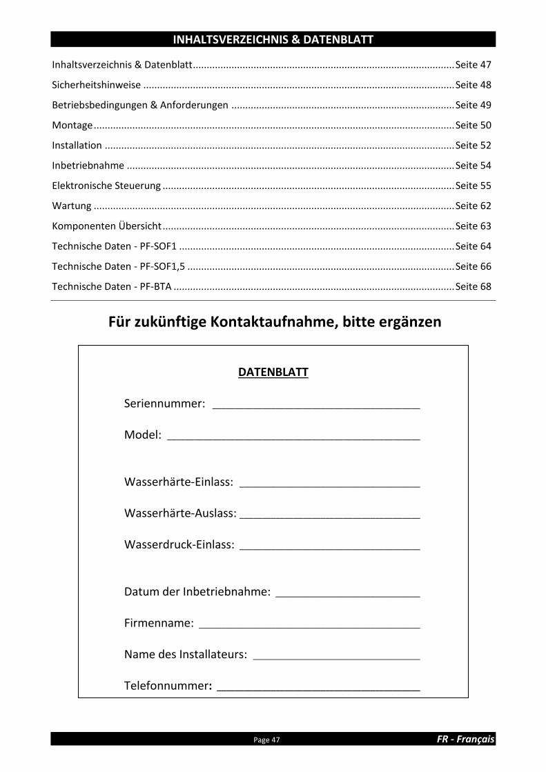
INHALTSVERZEICHNIS & DATENBLATT
Page 47 FR - Français
Inhaltsverzeichnis & Datenblatt ............................................................................................... Seite 47
Sicherheitshinweise ................................................................................................................. Seite 48
Betriebsbedingungen & Anforderungen ................................................................................. Seite 49
Montage ................................................................................................................................... Seite 50
Installation ............................................................................................................................... Seite 52
Inbetriebnahme ....................................................................................................................... Seite 54
Elektronische Steuerung .......................................................................................................... Seite 55
Wartung ................................................................................................................................... Seite 62
Komponenten Übersicht .......................................................................................................... Seite 63
Technische Daten - PF-SOF1 .................................................................................................... Seite 64
Technische Daten - PF-SOF1,5 ................................................................................................. Seite 66
Technische Daten - PF-BTA ...................................................................................................... Seite 68
Für zukünftige Kontaktaufnahme, bitte ergänzen
DATENBLATT
Seriennummer: ______________________________________________
Model: ________________________________________________________ Wasserhärte-Einlass: ________________________________________ Wasserhärte-Auslass: ________________________________________ Wasserdruck-Einlass: ________________________________________
Datum der Inbetriebnahme: ________________________________
Firmenname: _________________________________________________
Name des Installateurs: _____________________________________ Telefonnummer: _____________________________________________
SICHERHEITSHINWEISE
DE - Deutsch Seite 48
• Bitte lesen Sie die Bedienungsanleitung bevor Sie die Anlage installieren und in Betrieb nehmen. Diese enthält wichtige Informationen über Sicherheitshinweise, Inbetriebnahme, Gebrauch und Wartung des erworbenen Produkts. Das Gerät das Sie erhalten haben, kann von den Fotos/Abbildungen/Beschreibungen in dieser Anleitung abweichen.
• Nichtbeachtung der Anweisungen kann zu körperlichen Verletzungen
oder zu Schäden am Gerät führen. Nur wenn die Montage, Inbetrieb-nahme und Wartung der Anlage sachgemäß durchgeführt wird, kann eine langfristige Funktionstüchtigkeit gewährleistet werden.
• Die Anlage wandelt hartes in weiches Wasser um, indem sie die gelösten
Härtebildner durch Ionenaustausch entfernt; andere Verunreinigungen werden nicht entfernt. Die Anlage wird verschmutztes Wasser nicht reinigen und produziert kein Trinkwasser!
• Die Installation der Anlage sollte nur von einer sachkundigen Person
erfolgen die zusätzlich über alle notwendigen gesetzlichen Regelungen Kenntnis hat. Alle Sanitär- und elektrischen Anschlüsse müssen in Übereinstimmung mit den örtlichen Vorschriften durchgeführt werden.
• Überprüfen Sie vor der Inbetriebnahme ob die Anlage Schäden aufweist.
Installieren und Gebrauchen Sie die Anlage nicht, wenn diese Schäden aufweist.
• Benutzen Sie für den Transport einen Handwagen. Transportieren Sie die
Anlage nie auf der Schulter um Unfälle oder Verletzungen vorzubeugen. Legen Sie die Anlage nie auf die Seite.
• Bewahren Sie diese Anleitung an einem sicheren Ort auf um
sicherzustellen, dass sich auch andere Benutzer mit dem Inhalt vertraut machen können.
• Die Anlage wurde unter den geltenden gesetzlichen
Sicherheitsbestimmungen und Vorschriften hergestellt. Durch unsachgemäße Reparaturen können unvorhergesehen Gefahren für den Benutzer entstehen, wofür dann der Hersteller nicht verantwortlich gemacht werden kann. Deshalb sollten Reparaturen nur von geschulten Technikern durchgeführt werden.
• Aus Umweltschutzgründen sollte die Anlage entsprechend den geltenden
Umweltschutzgesetzen entsorgt werden.

BETRIEBSBEDINGUNGEN & ANFORDERUNGEN
Page 49 FR - Français
• BETRIEBSDRUCK MIN-MAX: 1,4-8,0 bar / 20-116 psi diese Anlage hat die optimale Leistung bei einem Betriebsdruck von
3 bar (45 psi) ±½ bar (7 psi); im Falle eines niedrigeren oder höheren Betriebsdruck kann die Leistung negativ beeinflusst werden.
kontrollieren Sie den Wasserdruck regelmäßig; Je nach Tageszeit, Wochentag oder sogar Jahreszeit kann er sehr stark schwanken.
berücksichtigen Sie, dass der Wasserdruck nachts erheblich höher sein kann als tagsüber.
wenn nötig, installieren Sie einen Wasserdruckminderer vor der Anlage.
Installieren Sie einen Druckerhöhungsanlage, wenn es wahrscheinlich ist, dass der Wasserdruck nicht das erforderlichen Minimum erreichen kann.
• BETRIEBSTEMPERATUR MIN-MAX: 2-48 °C / 35-120 °F installieren Sie die Anlage nicht in einer Räumlichkeit, wo zu hohe
oder zu niedrige Umgebungstemperaturen herrschen.
die Anlage ist nicht für den Außenbereich geeignet.
installieren Sie die Anlage nicht in direkter Nähe zu einem Heizkessel oder Wärmetauscher; lassen Sie mindestens 3 Meter (10 ft) Rohrleitung zwischen dem Ausgang der Anlage und dem Eingang eines Heizkessels Platz; Installieren Sie immer ein Rückschlagventil am Auslass der Anlage.
• ELEKTRISCHE VERBINDUNG: die Anlage funktioniert mit 24 V; bitte nutzen Sie diese Anlage immer
nur in Kombination mit dem mitgelieferten Netzteil.
Im Falle von Schäden an den Stromversorgungskabel des Netzteils, trennen Sie sofort das Netzteil aus der Steckdose und erstetzen Sie das Netzteil.
vergewissern Sie sich, dass diese Anlage mit einer Steckdose verbunden ist, die sich an einen trockenen Ort befindet und mit einem Überspannungsschutz (Sicherung) ausgestattet ist.

MONTAGE
DE - Deutsch Seite 50
INHALT ÜBERPRÜFEN
Die Bilder in dieser Anleitung können vom Aussehen Ihrer Anlage abweichen!
Zur Erleichterung des Transports und der Installation wird das Harz in separaten Säcken von 25 Ltr mitgeliefert; es muss vor Ort, nach der Positionierung des Drucktanks, eingefüllt werden.
Vergleichen Sie den Inhalt der Lieferung mit der Lieferübersicht am Ende dieser Anleitung. Identifizieren Sie und legen Sie die verschiedenen Komponenten um die Montage zu erleichtern.
SIMPLEX (PF-SOF1-SIM & PF-SOF1,5-SIM)
Ein Simplex System besteht aus einem einzigen Enthärtungsmodul (Drucktank, Harz, Steuerventil und Zubehör).
Während des normales Betriebs liefert das Simplex System enthärtetem Wasser. Sobald es eine Regeneration einleitet, geht es automatisch in hartes Wasser Bypass um eine ununterbrochene Versorgung mit unbehandeltem Wasser zu gewährleisten. Es ist möglich einen Simplex System auf ein Duplex System umzuwandeln, durch Zugabe eines zweiten Simplex System.
DUPLEX ALTERNIEREND (PF-SOF1-ALT & PF-SOF1,5-ALT)
Ein Duplex ALTERNIEREND System besteht aus 2 Simplex Systeme, die: - hydraulisch parallel installiert sind; - miteinander verbunden sind durch ein InterConnect
Kabel; - beide über ein stromlos geschlossen Magnetventil
(sogenannte Service-Ventil) am Ausgang jeder Simplex System verfügen; dieses Service-Ventil wird durch die elektronische Steuerung des Simplex System gesteuert und aktiviert während des Betriebszyklus, um den Ausgang des jeweiligen Simplex System zu öffnen;
- einen Salzbehälter, mit 2 Soleventilen, benutzen. Während des normales Betriebs ist nur 1 der 2 Simplex Systeme in Betrieb, während das andere regeneriert bzw. ‘im Standby’ ist! Sobald das erste System eine Regeneration einleitet, geht das zweite System in Betrieb, um eine ununterbrochene Versorgung mit behandeltem Wasser zu gewährleisten. Im Falle eines Stromausfalls, werden beide Service-Ventile deaktiviert werden, was bedeutet, den Ausgang der beiden Simplex Systeme wird verschlossen, um den Durchfluss von (möglicherweise hartem) Wasser zu verhindern.
DUPLEX PARALLEL (PF-SOF1-PRL & PF-SOF1,5-PRL)
Ein Duplex PARALLEL System besteht aus 2 Simplex Systeme, die: - hydraulisch parallel installiert sind;
- miteinander verbunden sind durch ein InterConnect Kabel;
- über ein stromlos offen Magnetventil (sogenannte Service-Ventil) am Ausgang jeder Simplex System verfügen; dieses Service-Ventil wird durch die elektronische Steuerung des Simplex System gesteuert und aktiviert während der gesamten Dauer der Regeneration, um den Standard 'hartes Wasser Bypass während der Regeneration' zu schließen;
- einen Salzbehälter, mit 2 Soleventilen, benutzen. Während des normales Betriebs, sind beide Simplex Systeme in Betrieb, mit einer Verdoppelung der Durchfluss zur Folge! Wenn einer der Simplex Systeme eine Regeneration einleitet, kommuniziert es sofort seinen Status zu das andere Simplex System über das InterConnect Kabel, um sicher zu stellen dass das andere Simplex System in Betrieb bleibt, und so eine ununterbrochene Versorgung mit behandeltem Wasser zu gewährleisten. Im Falle eines Stromausfalls, werden alle Service-Ventile deaktiviert werden, was bedeutet, den Ausgang aller Simplex Systeme wird geöffnet um eine ununterbrochene Versorgung mit Wasser zu gewährleisten. Für die korrekte Montage, wiederholen Sie die verschiedenen Montageschritte, bis beide Simplex Systeme montiert und richtig positioniert sind. Für große Installationen mit einem großen Bedarf an aufbereitetem Wasser, können 2 oder mehr Duplex Systeme problemlos hydraulisch parallel installiert werden, um den Durchfluss und die Enthärtungskapazität zu verdoppeln/verdreifachen/...
EINFÜLLEN DES HARZ
1. Stellen Sie den Drucktank in der richtigen Einbauort;
positionieren Sie diesen auf einer ebenen Oberfläche. Achten Sie darauf dass rundherum genug Platz ist, um Wartungsarbeiten problemlos durchzuführen zu können.
2. Positionieren Sie das Steigrohr aufrecht und Zentriert im Drucktank; dichten Sie den oben Steigrohrrand mit etwas Klebeband ab, um das Eindringen von Harz in das Steigrohr zu verhindern.
3. Füllen Sie den Drucktank mit Wasser bis eine Wasserhöhe von ±30 cm erreicht ist; während der Befüllung des Drucktanks dient dieses Wasser als Schutz für die Unterseite des Drucktanks und die untere Verteilerdüse.
4. Mit Hilfe eines Trichters befüllen Sie den Drucktank mit Harz und achten darauf, dass das Steigrohr zentriert in der Öffnung des Drucktanks verbleibt.
5. Reinigen Sie die Öffnung des Drucktanks, besonders das Gewinde.
6. Entfernen Sie das Klebeband oben am Steigrohr.
STEUERVENTIL
nur für PF-SOF1
1. Stellen sie sicher dass der O-Ring in die Steigleitung des
Steuerventils und der Drucktank-O-Ring (rund um den Gewinde des Steuerventils) sich an der richtigen Position befinden.
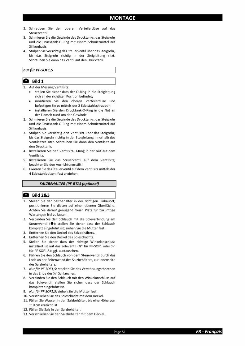
MONTAGE
Page 51 FR - Français
2. Schrauben Sie den oberen Verteilerdüse auf das Steuerventil.
3. Schmieren Sie die Gewinde des Drucktanks, das Steigrohr und die Drucktank-O-Ring mit einem Schmiermittel auf Silikonbasis.
4. Stülpen Sie vorsichtig das Steuerventil über das Steigrohr, bis das Steigrohr richtig in der Steigleitung sitzt. Schrauben Sie dann das Ventil auf den Drucktank.
nur für PF-SOF1,5
Bild 1
1. Auf der Messing Ventilsitz:
• stellen Sie sicher dass der O-Ring in die Steigleitung sich an der richtigen Position befindet;
• montieren Sie den oberen Verteilerdüse und befestigen Sie es mittels der 2 Edelstahlschrauben;
• installieren Sie den Drucktank-O-Ring in die Nut an der Flansch rund um den Gewinde.
2. Schmieren Sie die Gewinde des Drucktanks, das Steigrohr und die Drucktank-O-Ring mit einem Schmiermittel auf Silikonbasis.
3. Stülpen Sie vorsichtig den Ventilsitz über das Steigrohr, bis das Steigrohr richtig in der Steigleitung innerhalb des Ventilsitzes sitzt. Schrauben Sie dann den Ventilsitz auf den Drucktank.
4. Installieren Sie den Ventilsitz-O-Ring in der Nut auf dem Ventilsitz.
5. Installieren Sie das Steuerventil auf dem Ventilsitz; beachten Sie den Ausrichtungsstift!
6. Fixieren Sie das Steuerventil auf dem Ventilsitz mittels der 4 Edelstahlbolzen; fest anziehen.
SALZBEHÄLTER (PF-BTA) (optional)
Bild 2&3
1. Stellen Sie den Salzbehälter in der richtigen Einbauort; positionieren Sie diesen auf einer ebenen Oberfläche. Achten Sie darauf genügend freien Platz für zukünftige Wartungen frei zu lassen.
2. Verbinden Sie den Schlauch mit die Soleverbindung am Steuerventil (); stellen Sie sicher dass der Schlauch komplett eingeführt ist; ziehen Sie die Mutter fest.
3. Entfernen Sie den Deckel des Salzbehälters. 4. Entfernen Sie den Deckel des Soleschachts. 5. Stellen Sie sicher dass der richtige Winkelanschluss
installiert ist auf das Soleventil (⅜” für PF-SOF1 oder ½” für PF-SOF1,5); ggf. austauschen.
6. Führen Sie den Schlauch von dem Steuerventil durch das Loch an der Seitenwand des Salzbehälters, zur Innenseite des Salzbehälters.
7. Nur für PF-SOF1,5: stecken Sie das Verstärkungsröhrchen in das Ende des ½” Schlauches.
8. Verbinden Sie den Schlauch mit den Winkelanschluss auf das Soleventil; stellen Sie sicher dass der Schlauch komplett eingeführt ist.
9. Nur für PF-SOF1,5: ziehen Sie die Mutter fest. 10. Verschließen Sie das Soleschacht mit dem Deckel. 11. Füllen Sie Wasser in den Salzbehälter, bis eine Höhe von
±10 cm erreicht ist. 12. Füllen Sie Salz in den Salzbehälter. 13. Verschließen Sie den Salzbehälter mit dem Deckel.

INSTALLATION
DE - Deutsch Seite 52
EINLASS & AUSLASS
Im Falle groben Verunreinigungen in der Eingangsleitung, empfehlen wir einen Sedimentfilter zu installieren vor der Anlage.
Für die Verbindung der Anlage zum Wasserverteilungssystem empfehlen wir dringend die Benutzung von flexiblen Schläuchen; verwenden Sie Schläuche mit großen Durchmesser um Druckverluste zu verhindern.
Wir empfehlen dringend die Installation ein Bypass-System (nicht im Lieferumfang enthalten) zu installieren, um, im Falle einer Reparatur, die Anlage von der Wasserverteilung zu isolieren und eine Wasserversorgung (unbehandelt) garantieren zu können.
nur für PF-SOF1-SIM: SIMPLEX mit originalem Bypass (optional)
Bild 4
= Hauptwasserleitung (unbehandeltes Wasser) ❖ = Einlass Steuerventil (unbehandeltes Wasser) = Auslass Steuerventil (behandeltes Wasser) = Wasserverteilungssystem (behandeltes Wasser) 1. Schrauben Sie den original Bypass auf den Einlass/Auslass
des Steuerventils (❖&); achten Sie auf die Verwendung von Dichtungen. Drehen Sie die Muttern mit der Hand fest.
2. Schrauben Sie die Anschlüsse auf den Bypass (&); achten Sie auf die Verwendung von Dichtungen. Drehen Sie die Muttern mit der Hand fest.
3. Verbinden Sie die Hauptwasserleitung mit dem Anschluss am Eingang vom Bypass ().
4. Verbinden Sie das Wasserverteilungssystem mit dem Anschluss am Ausgang vom Bypass ().
nur für PF-SOF1-SIM: SIMPLEX mit 3-Ventil-Anschluss-Satz (nicht enth.)
Bild 5
= Einlass Steuerventil (unbehandeltes Wasser) ❖ = Auslass Steuerventil (behandeltes Wasser) 1. Installieren Sie den 3-Ventil-Anschluss-Satz. 2. Schrauben Sie die Anschlüsse auf den Einlass/Auslass des
Steuerventils (&❖); achten Sie auf die Verwendung von Dichtungen. Drehen Sie die Muttern mit der Hand fest.
3. Verbinden Sie das Eingangs-Ventil (IN) des 3-Ventil-Anschluss-Satzes mit dem Anschluss am Ventileinlass ().
4. Verbinden Sie das Ausgangs-Ventil (OUT) des 3-Ventil-Anschluss-Satzes mit dem Anschluss am Ventilauslass (❖).
5. Verbinden Sie die Hauptwasserleitung mit dem Eingang des 3-Ventil-Anschluss-Satzes.
6. Verbinden Sie das Wasserverteilungssystem mit dem Ausgang des 3-Ventil-Anschluss-Satzes.
nur für PF-SOF1-ALT und PF-SOF1-PRL: DUPLEX mit Multi-Ventil-Anschluss-Satz (nicht enth.)
Bild 6
= Einlass Steuerventil (unbehandeltes Wasser) ❖ = Auslass Steuerventil (behandeltes Wasser) = Service-Ventil 1. Installieren Sie den Multi-Ventil-Anschluss-Satz. 2. Schrauben Sie die Anschlüsse auf den Einlass/Auslass des
Steuerventils (&❖); achten Sie auf die Verwendung von Dichtungen. Drehen Sie die Muttern mit der Hand fest.
3. Schrauben Sie das Service-Ventil () auf den Anschluss am Ventilauslass (❖); respektieren sie die Durchfluss-richtung (siehe Pfeil an der Unterseite des Service-Ventil); verwenden Sie ein geeignetes Dichtmittel.
4. Verbinden Sie das Eingangs-Ventil (IN) des Multi-Ventil-Anschluss-Satzes mit dem Anschluss am Ventileinlass ().
5. Verbinden Sie das Ausgangs-Ventil (OUT) des Multi-Ventil-Anschluss-Satzes mit dem Service-Ventil ().
6. Wiederholen Sie die Schritte 2-5 für beide Simplex Systeme.
7. Verbinden Sie die Hauptwasserleitung mit dem Eingang des Multi-Ventil-Anschluss-Satzes.
8. Verbinden Sie das Wasserverteilungssystem mit dem Ausgang des Multi-Ventil-Anschluss-Satzes.
nur für PF-SOF1-SIM: SIMPLEX mit 3-Ventil-Anschluss-Satz (nicht enth.)
Bild 7
= Einlass Steuerventil (unbehandeltes Wasser) ❖ = Auslass Steuerventil (behandeltes Wasser) = PVC Ellenbogen = Einlass Durchflussmesser = Auslass Durchflussmesser 1. Installieren Sie den 3-Ventil-Anschluss-Satz. 2. Stecken Sie die Anschlüsse in den Einlass/Auslass des
Steuerventils (&❖); achten Sie darauf die O-Ringe nicht zu beschädigen. Installieren Sie die Muttern und drehen Sie die mit der Hand fest.
3. Schrauben Sie den PVC Ellenbogen () auf den Anschluss am Ventilauslass (❖); verwenden Sie ein geeignetes Dichtmittel.
4. Stecken Sie die Anschlüsse in den Einlass/Auslass des Durchflussmessers (&); achten Sie darauf die O-Ringe nicht zu beschädigen. Installieren Sie die Muttern und drehen Sie die mit der Hand fest.
5. Schrauben Sie den Durchflussmesser () in den PVC Ellenbogen (); respektieren Sie die Durchflussrichtung (siehe Pfeil); verwenden Sie ein geeignetes Dichtmittel.
6. Schließen Sie das Durchflussmesser-Kabel aus dem Steuerventil an den Durchflussmesser; befestigen Sie es mit Hilfe der Schraube.
7. Verbinden Sie das Eingangs-Ventil (IN) des 3-Ventil-Anschluss-Satzes mit dem Anschluss am Ventileinlass ().
8. Verbinden Sie das Ausgangs-Ventil (OUT) des 3-Ventil-Anschluss-Satzes mit dem Anschluss am Durchflussmesserauslass ().
9. Verbinden Sie die Hauptwasserleitung mit dem Eingang des 3-Ventil-Anschluss-Satzes.
10. Verbinden Sie das Wasserverteilungssystem mit dem Ausgang des 3-Ventil-Anschluss-Satzes.

INSTALLATION
Page 53 FR - Français
nur für PF-SOF1,5-ALT und PF-SOF1,5-PRL: DUPLEX mit Multi-Ventil-Anschluss-Satz (nicht enth.)
Bild 8
= Einlass Steuerventil (unbehandeltes Wasser) ❖ = Auslass Steuerventil (behandeltes Wasser) = PVC Ellenbogen = Einlass Durchflussmesser = Auslass Durchflussmesser = Service-Ventil 1. Installieren Sie den Multi-Ventil-Anschluss-Satz. 2. Stecken Sie die Anschlüsse in den Einlass/Auslass des
Steuerventils (&❖); achten Sie darauf die O-Ringe nicht zu beschädigen. Installieren Sie die Muttern und drehen Sie die mit der Hand fest.
3. Schrauben Sie den PVC Ellenbogen () auf den Anschluss am Ventilauslass (❖); verwenden Sie ein geeignetes Dichtmittel.
4. Stecken Sie die Anschlüsse in den Einlass/Auslass des Durchflussmessers (&); achten Sie darauf die O-Ringe nicht zu beschädigen. Installieren Sie die Muttern und drehen Sie die mit der Hand fest.
5. Schrauben Sie den Durchflussmesser () in den PVC Ellenbogen (); respektieren Sie die Durchflussrichtung (siehe Pfeil); verwenden Sie ein geeignetes Dichtmittel.
6. Schließen Sie das Durchflussmesser-Kabel aus dem Steuerventil an den Durchflussmesser; befestigen Sie es mit Hilfe der Schraube.
7. Schrauben Sie das Service-Ventil () auf dem Anschluss am Durchflussmesserauslass (); respektieren sie die Durchfluss-richtung (siehe Pfeil an der Unterseite des Service-Ventil); verwenden Sie ein geeignetes Dichtmittel.
8. Verbinden Sie das Eingangs-Ventil (IN) des Multi-Ventil-Anschluss-Satzes mit dem Anschluss am Ventileinlass ().
9. Verbinden Sie das Ausgangs-Ventil (OUT) des Multi-Ventil-Anschluss-Satzes mit dem Ausgang des Service-Ventils ().
10. Wiederholen Sie die Schritte 2-8 für beide Simplex Systeme.
11. Verbinden Sie die Hauptwasserleitung mit dem Eingang des Multi-Ventil-Anschluss-Satzes.
12. Verbinden Sie das Wasserverteilungssystem mit dem Ausgang des Multi-Ventil-Anschluss-Satzes.
ABFLUSS
Wir empfehlen die Verwendung eines Standrohrs mit Geruchsverschluss.
Um einen Rückfluss von Abwasser in der Anlage zu verhindern, achten Sie auf einen ausreichenden Luftspalt zwischen dem Ende der Ablaufschlauch oder Ablaufleitung und den Abwassersystem.
Benutzen Sie immer separate Schläuche für das (die) Steuerventil(e) (Spülwasser) und den Überlauf des Salzbehälters.
Positionieren Sie den Ablaufschlauch so, dass der Gegendruck so gering wie möglich ist; vermeiden Sie Knicke und unnötige Erhöhungen.
Achten Sie darauf, dass das Abwassersystem für die Spülwasserfluss der Anlage geeignet ist.
nur für PF-SOF1:
Bild 9
1. Verbinden Sie den 19 mm Schlauch mit dem Ablaufbogen des Steuerventils (); sichern Sie diesen mit der Klammer.
2. Führen Sie den Ablaufschlauch zum Abwassersystem und verbinden Sie diesen; achten Sie auf einen ausreichenden Luftspalt zwischen dem Ende des Schlauchs und den Abwassersystem. Diese Leitung steht unter Druck und kann deshalb höher als Ihre Anlage installiert werden.
3. Für Duplex: wiederholen Sie die Schritte 1-2 für beide Simplex Systeme.
nur für PF-SOF1,5:
Bild 10
1. Verbinden Sie eine Leitung mit dem 1” BSP Außengewinde Ablaufadapter Steuerventils (); verwenden Sie ein geeignetes Dichtmittel.
2. Führen Sie die Leitung zum Abwassersystem und verbinden Sie diesen; achten Sie auf einen ausreichenden Luftspalt zwischen dem Ende der Leitung und den Abwassersystem. Diese Leitung steht unter Druck und kann deshalb höher als Ihre Anlage installiert werden.
3. Für Duplex: wiederholen Sie die Schritte 1-2 für beide Simplex Systeme.
PF-BTA: Salzbehälter (optional)
1. Verbinden Sie den 19 mm Schlauch mit die Überlaufwinkel des Salzbehälters; sichern Sie diesen mit der Klammer.
2. Führen Sie den Ablaufschlauch zum Abwassersystem und verbinden Sie diesen; achten Sie auf einen ausreichenden Luftspalt zwischen dem Ende des Schlauchs und den Abwassersystem. Diese Leitung steht NICHT unter Druck und kann deshalb NICHT höher als der Salzbehälter installiert werden.
SERVICE-VENTILE
(nur für Duplex)
Bild 11
1. Stecken Sie den DIN-Stecker am Kabel des Service-Ventils in die DIN-Buchse auf der Rückseite der elektronischen Steuerung jedes Steuerventils ().

INBETRIEBNAHME
DE - Deutsch Seite 54
ELEKTRISCH
1. Verbinden Sie das Stromkabel der Anlage an den Ausgang
des Netzteils. 2. Stecken Sie das Netzteil in die Steckdose.
DRUCK 1. Achten Sie darauf, dass der Bypass sich in 'bypass'
Stellung befindet. 2. Achten Sie darauf, dass die elektronische Steuerung(en)
sich in Betriebsmodus befindet(en). 3. Öffnen Sie die Hauptwasserleitung. 4. Öffnen Sie einen aufbereitetes Kaltwasserhahn der sich in
der Nähe der Anlage befindet und lassen Sie das Wasser einige Minuten laufen bis alle Luft und Verunreinigungen, die durch die Installation hervorgerufen wurden, ausgespült sind; schließen Sie den Hahn.
5. Setzen Sie behutsam die Anlage unter Druck:
• schließen Sie das Bypassventil;
• öffnen Sie das Auslassventil;
• öffnen Sie vorsichtig das Einlassventil. 6. Nach 2-3 Minuten, öffnen Sie einen aufbereitetes
Kaltwasserhahn der sich in der Nähe der Anlage befindet und lassen Sie das Wasser einige Minuten laufen um die Anlage zu entlüften und das Harz zu spülen (es ist normal, dass das Spülwasser leicht verfärbt ist!); schließen Sie den Wasserhahn.
7. Überprüfen Sie den Anlage und all seine hydraulischen Verbindungen auf Dichtigkeit.
8. Für Duplex: wiederholen Sie die Schritte 5-7 für beide Simplex Systeme.
ELEKTRONISCHE STEUERUNG
1. Programmieren Sie die elektronische Steuerung. 2. Für Duplex: wiederholen Sie Schritt 1 für beide Simplex
Systeme.
WASSERVERSCHNITT
In der Praxis wird die Resthärte beeinflusst durch den Einlassdruck, den Durchfluss und der Wasserhärte des Eingangswassers. Bei der Einstellung der Resthärte, stellen Sie sicher, diese Bedingungen sind ähnlich wie die tatsävhlichen Betriebsbedingungen.
DIREKT AM STEUERVENTIL
Bild 12.a
1. Stellen Sie die Resthärte des Wassers ein mittels des Verschneideventils, eingebaut auf der rechten Seite des Steuerventils:
• zur Härteanhebung: drehen Sie das Verschneideventil gegen den Uhrzeigersinn;
• zur Härtereduzierung: drehen Sie das Verschneideventil im Uhrzeigersinn.
2. Messen Sie die Resthärte des Wassers mit einer Wasserhärte-Testkit; gegebenenfalls nachstellen.
MIT ORIGINALEM BYPASS (optional)
Bild 12.b
1. Stellen Sie die Resthärte des Wassers ein mittels des Verschneideventils, eingebaut in der Auslassventil der Ab-Werk Bypass:
• zur Härteanhebung: drehen Sie das Verschneideventil gegen den Uhrzeigersinn;
• zur Härtereduzierung: drehen Sie das Verschneideventil im Uhrzeigersinn.
2. Messen Sie die Resthärte des Wassers mit einer Wasserhärte-Testkit; gegebenenfalls nachstellen.
START DER REGENERATION
1. Starten Sie eine manuelle Regeneration, durch Drücken
der scroll Taste; auf dem Display erscheint:
2. Lassen Sie die Anlage in dieser Position; wenn der Zähler bei 0 angelangt ist, wird eine Regeneration gestartet; um Zeit zu sparen, können Sie die zweite Stufe der Regeneration durch Drücken der scroll Taste, überspringen oder vorzeitig beenden, sobald das Display anzeigt dass das System in der zweiten Stufe der Regeneration ist.
3. Für Duplex: wiederholen Sie die Schritte 1-2 für beide Simplex Systeme.
INTERCONNECT KABEL
(nur für Duplex)
Bild 13
1. Verbinden Sie die Steuerventile mit einem InterConnect Kabel; stecken Sie die DIN-Stecker am InterConnect Kabel in den DIN-Buchsen auf der Rückseite der elektr. Steuerung jedes Steuerventils ().
ALTERNIEREND MODUS AKTIVIEREN (nur für Duplex Alternierend)
1. Auf einem der 2 Steuerventile, initiieren Sie eine
manuelle Regeneration, durch Drücken auf die scroll Taste; auf dem Display erscheint :
2. Lassen Sie die Anlage in dieser Position; wenn der Zähler
bei 0 angelangt ist, wird eine Regeneration gestartet. 3. Um das Ventil durch die Regenerationsstufen zu schalten
und es in Standby Modus zu setzen, drücken Sie die scroll
Taste so oft, bis das Display zeigt:
Regen in 10 Sek
Stdby 1000 L –
TotVol: 1234567L
Regen in 10 Sek
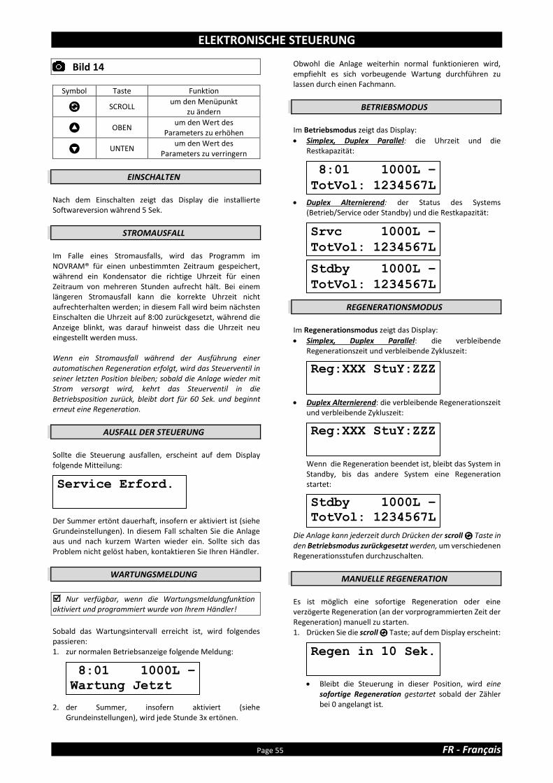
ELEKTRONISCHE STEUERUNG
Page 55 FR - Français
Bild 14
Symbol Taste Funktion
SCROLL um den Menüpunkt
zu ändern
OBEN um den Wert des
Parameters zu erhöhen
UNTEN um den Wert des
Parameters zu verringern
EINSCHALTEN
Nach dem Einschalten zeigt das Display die installierte Softwareversion während 5 Sek.
STROMAUSFALL
Im Falle eines Stromausfalls, wird das Programm im NOVRAM® für einen unbestimmten Zeitraum gespeichert, während ein Kondensator die richtige Uhrzeit für einen Zeitraum von mehreren Stunden aufrecht hält. Bei einem längeren Stromausfall kann die korrekte Uhrzeit nicht aufrechterhalten werden; in diesem Fall wird beim nächsten Einschalten die Uhrzeit auf 8:00 zurückgesetzt, während die Anzeige blinkt, was darauf hinweist dass die Uhrzeit neu eingestellt werden muss. Wenn ein Stromausfall während der Ausführung einer automatischen Regeneration erfolgt, wird das Steuerventil in seiner letzten Position bleiben; sobald die Anlage wieder mit Strom versorgt wird, kehrt das Steuerventil in die Betriebsposition zurück, bleibt dort für 60 Sek. und beginnt erneut eine Regeneration.
AUSFALL DER STEUERUNG
Sollte die Steuerung ausfallen, erscheint auf dem Display folgende Mitteilung:
Der Summer ertönt dauerhaft, insofern er aktiviert ist (siehe Grundeinstellungen). In diesem Fall schalten Sie die Anlage aus und nach kurzem Warten wieder ein. Sollte sich das Problem nicht gelöst haben, kontaktieren Sie Ihren Händler.
WARTUNGSMELDUNG
Nur verfügbar, wenn die Wartungsmeldungfunktion aktiviert und programmiert wurde von Ihrem Händler!
Sobald das Wartungsintervall erreicht ist, wird folgendes passieren: 1. zur normalen Betriebsanzeige folgende Meldung:
2. der Summer, insofern aktiviert (siehe Grundeinstellungen), wird jede Stunde 3x ertönen.
Obwohl die Anlage weiterhin normal funktionieren wird, empfiehlt es sich vorbeugende Wartung durchführen zu lassen durch einen Fachmann.
BETRIEBSMODUS
Im Betriebsmodus zeigt das Display:
• Simplex, Duplex Parallel: die Uhrzeit und die Restkapazität:
• Duplex Alternierend: der Status des Systems (Betrieb/Service oder Standby) und die Restkapazität:
REGENERATIONSMODUS
Im Regenerationsmodus zeigt das Display:
• Simplex, Duplex Parallel: die verbleibende Regenerationszeit und verbleibende Zykluszeit:
• Duplex Alternierend: die verbleibende Regenerationszeit und verbleibende Zykluszeit:
Wenn die Regeneration beendet ist, bleibt das System in Standby, bis das andere System eine Regeneration startet:
Die Anlage kann jederzeit durch Drücken der scroll Taste in den Betriebsmodus zurückgesetzt werden, um verschiedenen Regenerationsstufen durchzuschalten.
MANUELLE REGENERATION
Es ist möglich eine sofortige Regeneration oder eine verzögerte Regeneration (an der vorprogrammierten Zeit der Regeneration) manuell zu starten. 1. Drücken Sie die scroll Taste; auf dem Display erscheint:
• Bleibt die Steuerung in dieser Position, wird eine sofortige Regeneration gestartet sobald der Zähler bei 0 angelangt ist.
Reg:XXX StuY:ZZZ
8:01 1000L –
TotVol: 1234567L
Reg:XXX StuY:ZZZ
Srvc 1000L –
TotVol: 1234567L
Stdby 1000L –
TotVol: 1234567L
Stdby 1000L –
TotVol: 1234567L
Regen in 10 Sek.
Service Erford.
8:01 1000L –
Wartung Jetzt

ELEKTRONISCHE STEUERUNG
DE - Deutsch Seite 56
• Um diesen Modus zu verlassen, drücken Sie die scroll
Taste bevor die Anzeige 0 erreicht hat; auf dem Display erscheint:
• Bleibt die Steuerung in dieser Position, wird eine verzögerte Regeneration initiiert bei der angegebenen vorprogrammierten Zeit der Regeneration.
• Um diesen Modus zu verlassen, drücken Sie die scroll
Taste; die Steuerung schaltet auf den Betriebsmodus zurück.
URLAUBSMODUS
Es ist möglich, die Anlage in der Urlaubsmodus zu versetzen; dies wird vereiteln dass automatische Regeneration erfolgt, doch wird dafür sorgen dass die Anlage automatisch regeneriert wird am Ende des Urlaubszyklus. 1. Drücken Sie wiederholtes die scroll Taste, bis auf dem
Display folgendes erscheint:
• Drücken Sie die oben oder unten Taste um den Urlaubsmodus zu aktivieren durch einstellen der Anzahl vollen Tagen außer Hause, oder den Urlaubsmodus zu deaktivieren (AUS).
Sobald die Steuerung wieder in Betriebsmodus ist, erscheint auf dem Display:
Der Urlaubsmodus wird automatisch beendet, wenn eine Regeneration manuell gestartet wird!
PROGRAMMIERANLEITUNG - GRUNDEINSTELLUNGEN
Bevor Sie den Programmiermodus wählen, stellen Sie sicher, dass sich die Anlage im Betriebsmodus befindet.
Wenn in einem Zeitraum von 5 Min keine Taste gedrückt wird, schaltet die Steuerung automatisch auf den Betriebsmodus zurück; alle vorgenommenen Änderungen werden NICHT gespeichert!
1. Drücken Sie die scroll Taste und halten Sie diese 2 Sek.
bis das Display zeigt:
• Drücken Sie die oben oder unten Taste um die Sprache einzustellen.
2. Drücken Sie erneut die scroll Taste; auf dem Display
erscheint:
• Drücken Sie die oben oder unten Taste um die Uhrzeit einzustellen.
3. Drücken Sie erneut die scroll Taste; auf dem Display
erscheint:
• Drücken Sie die oben oder unten Taste um die Masseinheit für die Wasserhärte einzustellen. Achten Sie darauf es ist identisch mit die Masseinheit der Wasserhärte-Testkit oder der Wasseranalysebericht, der verwendet wird um die Härte des Eingangswassers zu bestimmen!
4. Drücken Sie erneut die scroll Taste; auf dem Display
erscheint:
• Drücken Sie die oben oder unten Taste um die Wasserhärte des Eingangswassers einzustellen.
5. Drücken Sie erneut die scroll Taste; auf dem Display
erscheint:
• Drücken Sie die oben oder unten Taste um den Summermodus zu aktivieren oder zu deaktivieren.
Reg.Zeit: 2:00
8:01 Urlaub
Urlaub: AUS
Sprache: Deutsch
Uhrzeit: 8:01
Einh.Härte: °f
Härte: XX °f
Summer: AN

ELEKTRONISCHE STEUERUNG
Page 57 FR - Français
6. Drücken Sie erneut die scroll Taste; auf dem Display erscheint:
• Drücken Sie die oben oder unten Taste um das Programm im NOVRAM® zu speichern und die Programmierung zu beenden.
PROGRAMMIERANLEITUNG – KONFIGURATIONSPARAMETER
Bevor Sie den Programmiermodus wählen, stellen Sie sicher, dass sich die Anlage im Betriebsmodus befindet.
Alle Konfigurationsparameter dieser Anlage wurden in der Fabrik vorprogrammiert, um eine optimale Leistung für eine Vielzahl von Anwendungen und Situationen zu bieten. Allerdings kann es notwendig oder wünschenswert sein, einen dieser Parameter zu ändern um eine weitere Optimierung der Leistung oder der spezifischen Anforderungen gerecht zu werden.
Wenn in einem Zeitraum von 5 Min keine Taste gedrückt wird, schaltet die Steuerung automatisch auf den Betriebsmodus zurück; alle vorgenommenen Änderungen werden NICHT gespeichert!
nur für PF-SOF1-SIM & PF-SOF1,5-SIM
1. Drücken Sie die scroll Taste und halten Sie diese 6 Sek.
bis das Display zeigt: 2. Innerhalb 10 Sek, drücken Sie die oben Taste; auf dem
Display erscheint:
• Drücken Sie die oben oder unten Taste um die Maßeinheiten (Metrisch oder English-US) einzustellen.
3. Drücken Sie erneut die scroll Taste; auf dem Display
erscheint:
• Drücken Sie die oben oder unten Taste um die Wartungs-Erinnerungsfunktion zu aktivieren, indem Sie das gewünschte Wartungsintervall (in Monaten) einstellen oder die Wartungs-Erinnerungsfunktion zu deaktivieren.
4. Drücken Sie erneut die scroll Taste; auf dem Display
erscheint:
• Drücken Sie die oben oder unten Taste um die Austauschkapazität pro Liter Harz einzustellen.
5. Drücken Sie erneut die scroll Taste; auf dem Display
erschein:
System Kontrolle
ExKap:5.5°f M3/L
Einh.:Metric
Kor Alterung2.0%
Service: 24 Mon
Verlassen

ELEKTRONISCHE STEUERUNG
DE - Deutsch Seite 58
• Drücken Sie die oben oder unten Taste um den Alterskorrekturfaktor (%/Jahr) einzustellen; dieser passt den durch die Alterung bedingte Kapazitätsverringerung des Harzes an.
6. Drücken Sie erneut die scroll Taste; auf dem Display
erscheint:
• Drücken Sie die oben oder unten Taste um die Harzmenge einzustellen.
7. Drücken Sie erneut die scroll Taste; auf dem Display
erscheint:
• Drücken Sie die oben oder unten Taste um die Anzahl der Tagen zwischen Regenerationen einzustellen.
8. Drücken Sie erneut die scroll Taste; auf dem Display
erscheint:
• Drücken Sie die oben oder unten Taste um die Länge der Regenerationsstufe einzustellen.
• Drücken Sie erneut die scroll Taste um zum nächsten Regenerationsstufe weiter zu gehen.
Stufe 1 Rückspülen
Stufe 2 Besalzen/Langsamspülen
Stufe 3 Schnellspülen/Solefüllen (PF-SOF1) Schnellspülen (PF-SOF1,5)
Stufe 4 Solefüllen (PF-SOF1,5)
9. Drücken Sie erneut die scroll Taste; auf dem Display
erscheint:
• Drücken Sie die oben oder unten Taste um die Art der Regeneration einzustellen:
Verz/Sofort: wenn die Restkapazität der Reservekapazität entspricht, wird eine verzögerte Regeneration zur programmierten Zeit der Regeneration gestartet; allerdings, wenn die Restkapazität 0 erreicht, bevor der programmierte Zeit de Regeneration erreicht ist, wird eine sofortiger Regeneration gestartet.
Sofort: wenn die Restkapazität 0 erreicht, wird eine sofortiger Regeneration gestartet. Hinweis: verzögerte manuelle Regeneration ist nicht verfügbar, wenn dieser Regenerations-modus ausgewählt ist.
Verzögert: wenn die Restkapazität der Reservekapazität entspricht, wird eine verzögerte Regeneration zur programmierten Zeit der Regeneration gestartet.
10. Drücken Sie erneut die scroll Taste; auf dem Display erscheint (nur wenn die Art der Regeneration programmiert wurde auf 'Verzögert' oder 'Verz/Sofort'):
• Drücken Sie die oben oder unten Taste um die Zeit der Regeneration einzustellen.
11. Drücken Sie erneut die scroll Taste; auf dem Display
erscheint (nur wenn die Art der Regeneration programmiert wurde auf 'Verzögert' oder 'Verz/Sofort'):
• Drücken Sie die oben oder unten Taste um die Reservekapazität einzustellen:
Variable: die Reservekapazität wird automatisch berechnet auf Grundlage der registrierten täglichen Wasserverbrauch.
Fix: drücken Sie die oben oder unten Taste um die Reservekapazität fest einzustellen.
12. Drücken Sie erneut die scroll Taste; auf dem Display
erscheint:
• Drücken Sie die oben oder unten Taste um die Funktion des Auxilliary Kontakt 2 zu einzustellen:
Regen: Aux.Kontakt ist während der gesamten Regeneration aktiv (nicht während der Zyklen “Befüllung Sole“ und „Bereitung Sole“)
Chlorzelle: Aux.Kontakt wird beim Start des Soleansaug-/Langsam-Spülen-Zyklus aktiviert. Durch erneutes Drücken der Scroll-Taste kann die Dauer der Chlorzellezellenaktivierung durch die Oben- und Unten-Taste eingestellt werden.
Wartung: Aux.Kontakt ist aktiviert, wenn die Wartungserinnerung ausgelöst wurde.
Error: Aux.Kontakt ist aktiv, wenn ein Timerfehler auftritt.
13. Drücken Sie erneut die scroll Taste; auf dem Display
erscheint:
• Drücken Sie die oben oder unten Taste um das Programm im NOVRAM® zu speichern und die Programmierung zu beenden.
Stufe 1: XX Min
Reg.Zeit: 2:00
Verlassen
Harz:XXX Ltr.
ZwangReg: 7 Tage
Reg.:Verz/Sofort
Reserve Variable
AUX2: Regen

ELEKTRONISCHE STEUERUNG
Page 59 FR - Français
nur für PF-SOF1-ALT & PF-SOF1,5-ALT
Jedes der 2 Simplex Systeme, die zusammen einen Duplex System formen, muss individuell programmiert werden; das Programm muss NICHT unbedingt die gleiche sein auf beiden Simplex Systeme!
1. Drücken Sie die scroll Taste und halten Sie diese 6 Sek.
bis das Display zeigt: 2. Innerhalb 10 Sek, drücken Sie die oben Taste; auf dem
Display erscheint:
• Drücken Sie die oben oder unten Taste um die Maßeinheiten (Metrisch oder English-US) einzustellen.
3. Drücken Sie erneut die scroll Taste; auf dem Display
erscheint:
• Drücken Sie die oben oder unten Taste um die Wartungs-Erinnerungsfunktion zu aktivieren, indem Sie das gewünschte Wartungsintervall (in Monaten) einstellen oder die Wartungs-Erinnerungsfunktion zu deaktivieren.
4. Drücken Sie erneut die scroll Taste; auf dem Display
erscheint:
• Drücken Sie die oben oder unten Taste um die Austauschkapazität pro Liter Harz einzustellen.
5. Drücken Sie erneut die scroll Taste; auf dem Display
erschein:
• Drücken Sie die oben oder unten Taste um den Alterskorrekturfaktor (%/Jahr) einzustellen; dieser passt den durch die Alterung bedingte Kapazitätsverringerung des Harzes an.
6. Drücken Sie erneut die scroll Taste; auf dem Display
erscheint:
• Drücken Sie die oben oder unten Taste um die Harzmenge einzustellen.
7. Drücken Sie erneut die scroll Taste; auf dem Display erscheint:
• Drücken Sie die oben oder unten Taste um die Anzahl der Tagen zwischen Regenerationen einzustellen.
8. Drücken Sie erneut die scroll Taste; auf dem Display
erscheint:
• Drücken Sie die oben oder unten Taste um die Länge der Regenerationsstufe einzustellen.
• Drücken Sie erneut die scroll Taste um zum nächsten Regenerationsstufe weiter zu gehen.
Stufe 1 Rückspülen
Stufe 2 Besalzen/Langsamspülen
Stufe 3 Schnellspülen/Solefüllen (PF-SOF1) Schnellspülen (PF-SOF1,5)
Stufe 4 Solefüllen (PF-SOF1,5)
9. Drücken Sie erneut die scroll Taste; auf dem Display
erscheint:
• Drücken Sie die oben oder unten Taste um die Funktion des Auxilliary Kontakt 2 zu einzustellen:
Regen: Aux.Kontakt ist während der gesamten Regeneration aktiv (nicht während der Zyklen “Befüllung Sole“ und „Bereitung Sole“)
Chlorzelle: Aux.Kontakt wird beim Start des Soleansaug-/Langsam-Spülen-Zyklus aktiviert. Durch erneutes Drücken der Scroll-Taste kann die Dauer der Chlorzellezellenaktivierung durch die Oben- und Unten-Taste eingestellt werden.
Wartung: Aux.Kontakt ist aktiviert, wenn die Wartungserinnerung ausgelöst wurde.
Error: Aux.Kontakt ist aktiv, wenn ein Timerfehler auftritt.
10. Drücken Sie erneut die scroll Taste; auf dem Display
erscheint:
• Drücken Sie die oben oder unten Taste um das Programm im NOVRAM® zu speichern und die Programmierung zu beenden.
11. Wiederholen Sie Schritt 1-10 für beide Simplex Systeme.
Verlassen
Stufe 1: XX Min
System Kontrolle
Harz:XXX Ltr.
ExKap:5.5°f M3/L
ZwangReg: 7 Tage
Einh.:Metric
Kor Alterung2.0%
Service: 24 Mon
AUX2: Regen
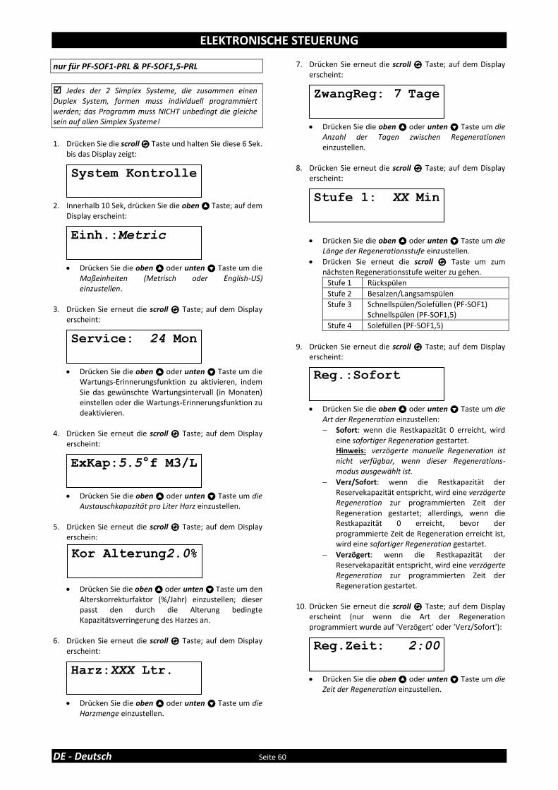
ELEKTRONISCHE STEUERUNG
DE - Deutsch Seite 60
nur für PF-SOF1-PRL & PF-SOF1,5-PRL
Jedes der 2 Simplex Systeme, die zusammen einen Duplex System, formen muss individuell programmiert werden; das Programm muss NICHT unbedingt die gleiche sein auf allen Simplex Systeme!
1. Drücken Sie die scroll Taste und halten Sie diese 6 Sek.
bis das Display zeigt: 2. Innerhalb 10 Sek, drücken Sie die oben Taste; auf dem
Display erscheint:
• Drücken Sie die oben oder unten Taste um die Maßeinheiten (Metrisch oder English-US) einzustellen.
3. Drücken Sie erneut die scroll Taste; auf dem Display
erscheint:
• Drücken Sie die oben oder unten Taste um die Wartungs-Erinnerungsfunktion zu aktivieren, indem Sie das gewünschte Wartungsintervall (in Monaten) einstellen oder die Wartungs-Erinnerungsfunktion zu deaktivieren.
4. Drücken Sie erneut die scroll Taste; auf dem Display
erscheint:
• Drücken Sie die oben oder unten Taste um die Austauschkapazität pro Liter Harz einzustellen.
5. Drücken Sie erneut die scroll Taste; auf dem Display
erschein:
• Drücken Sie die oben oder unten Taste um den Alterskorrekturfaktor (%/Jahr) einzustellen; dieser passt den durch die Alterung bedingte Kapazitätsverringerung des Harzes an.
6. Drücken Sie erneut die scroll Taste; auf dem Display
erscheint:
• Drücken Sie die oben oder unten Taste um die Harzmenge einzustellen.
7. Drücken Sie erneut die scroll Taste; auf dem Display erscheint:
• Drücken Sie die oben oder unten Taste um die Anzahl der Tagen zwischen Regenerationen einzustellen.
8. Drücken Sie erneut die scroll Taste; auf dem Display
erscheint:
• Drücken Sie die oben oder unten Taste um die Länge der Regenerationsstufe einzustellen.
• Drücken Sie erneut die scroll Taste um zum nächsten Regenerationsstufe weiter zu gehen.
Stufe 1 Rückspülen
Stufe 2 Besalzen/Langsamspülen
Stufe 3 Schnellspülen/Solefüllen (PF-SOF1) Schnellspülen (PF-SOF1,5)
Stufe 4 Solefüllen (PF-SOF1,5)
9. Drücken Sie erneut die scroll Taste; auf dem Display
erscheint:
• Drücken Sie die oben oder unten Taste um die Art der Regeneration einzustellen:
Sofort: wenn die Restkapazität 0 erreicht, wird eine sofortiger Regeneration gestartet. Hinweis: verzögerte manuelle Regeneration ist nicht verfügbar, wenn dieser Regenerations-modus ausgewählt ist.
Verz/Sofort: wenn die Restkapazität der Reservekapazität entspricht, wird eine verzögerte Regeneration zur programmierten Zeit der Regeneration gestartet; allerdings, wenn die Restkapazität 0 erreicht, bevor der programmierte Zeit de Regeneration erreicht ist, wird eine sofortiger Regeneration gestartet.
Verzögert: wenn die Restkapazität der Reservekapazität entspricht, wird eine verzögerte Regeneration zur programmierten Zeit der Regeneration gestartet.
10. Drücken Sie erneut die scroll Taste; auf dem Display
erscheint (nur wenn die Art der Regeneration programmiert wurde auf 'Verzögert' oder 'Verz/Sofort'):
• Drücken Sie die oben oder unten Taste um die Zeit der Regeneration einzustellen.
Reg.:Sofort
Reg.Zeit: 2:00
Stufe 1: XX Min
System Kontrolle
Harz:XXX Ltr.
ExKap:5.5°f M3/L
ZwangReg: 7 Tage
Einh.:Metric
Kor Alterung2.0%
Service: 24 Mon

ELEKTRONISCHE STEUERUNG
Page 61 FR - Français
11. Drücken Sie erneut die scroll Taste; auf dem Display erscheint (nur wenn die Art der Regeneration programmiert wurde auf 'Verzögert' oder 'Verz/Sofort'):
• Drücken Sie die oben oder unten Taste um die Reservekapazität einzustellen:
Variable: die Reservekapazität wird automatisch berechnet auf Grundlage der registrierten täglichen Wasserverbrauch.
Fix: drücken Sie erneut die scroll Taste und drücken Sie die oben oder unten Taste um die Reservekapazität fest einzustellen.
12. Drücken Sie erneut die scroll Taste; auf dem Display
erscheint:
• Drücken Sie die oben oder unten Taste um die Funktion des Auxilliary Kontakt 2 zu einzustellen:
Regen: Aux.Kontakt ist während der gesamten Regeneration aktiv (nicht während der Zyklen “Befüllung Sole“ und „Bereitung Sole“)
Chlorzelle: Aux.Kontakt wird beim Start des Soleansaug-/Langsam-Spülen-Zyklus aktiviert. Durch erneutes Drücken der Scroll-Taste kann die Dauer der Chlorzellezellenaktivierung durch die Oben- und Unten-Taste eingestellt werden.
Wartung: Aux.Kontakt ist aktiviert, wenn die Wartungserinnerung ausgelöst wurde.
Error: Aux.Kontakt ist aktiv, wenn ein Timerfehler auftritt.
13. Drücken Sie erneut die scroll Taste; auf dem Display
erscheint:
• Drücken Sie die oben oder unten Taste um das Programm im NOVRAM® zu speichern und die Programmierung zu beenden.
14. Wiederholen Sie Schritt 1-13 für beide Simplex Systeme.
Reserve Variable
Verlassen
AUX2: Regen
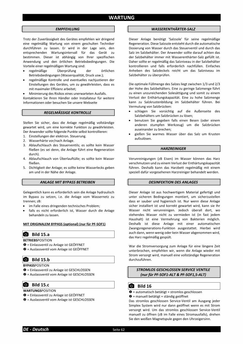
WARTUNG
DE - Deutsch Seite 62
EMPFEHLUNG
Trotz der Zuverlässigkeit des Gerätes empfehlen wir dringend eine regelmäßig Wartung von einem geschulten Techniker durchführen zu lassen. Er wird in der Lage sein, den entsprechenden Wartungsintervall für das Gerät zu bestimmen. Dieser ist abhängig von Ihrer spezifischen Anwendung und den örtlichen Betriebsbedingungen. Die Vorteile einer regelmäßigen Wartung sind:
• regelmäßige Überprüfung der örtlichen Betriebsbedingungen (Wasserqualität, Druck usw.);
• regelmäßige Kontrolle und eventuelles nachjustieren der Einstellungen des Gerätes, um zu gewährleisten, dass es mit maximaler Effizienz arbeitet;
• Minimierung des Risikos eines unerwarteten Ausfalls. Kontaktieren Sie Ihren Händler oder Installateur für weitere Informationen oder besuchen Sie unsere Webseite
REGELMÄSSIGE KONTROLLE
Stellen Sie sicher, dass die Anlage regelmäßig vollständige gewartet wird, um eine korrekte Funktion zu gewährleisten. Der Anwender sollte folgende Punkte selbst kontrollieren: 1. Einstellungen der elektron. Steuerung. 2. Wasserhärte vor/nach Anlage. 3. Ablaufschlauch des Steuerventils; es sollte kein Wasser
fließen (es sei denn, die Anlage führt eine Regeneration durch).
4. Ablaufschlauch von Überlauftülle; es sollte kein Wasser fließen.
5. Dichtigkeit der Anlage; es sollte keine Wasserlecks geben am und in der Nähe der Anlage.
ANLAGE MIT BYPASS BETREIBEN
Gelegentlich kann es erforderlich sein die Anlage hydraulisch im Bypass zu setzen, i.e. die Anlage vom Wassernetz zu trennen; zB:
• im Falle eines dringenden technisches Problem;
• falls es nicht erforderlich ist, Wasser durch die Anlage behandeln zu lassen.
MIT ORIGINALEM BYPASS (optional) (nur für PF-SOF1)
Bild 15.a
BETRIEBSPOSITION = Einlassventil zu Anlage ist GEÖFFNET ❖ = Auslassventil vom Anlage ist GEÖFFNET
Bild 15.b
BYPASSPOSITION = Einlassventil zu Anlage ist GESCHLOSSEN ❖ = Auslassventil vom Anlage ist GESCHLOSSEN
Bild 15.c
WARTUNGSPOSITION = Einlassventil zu Anlage ist GEÖFFNET ❖ = Auslassventil vom Anlage ist GESCHLOSSEN
WASSERENTHÄRTER-SALZ
Dieser Anlage benötigt 'Salzsole' für seine regelmäßige Regeneration. Diese Salzsole entsteht durch die automatische Dosierung von Wasser durch das Steuerventil und durch das Salz im Salzbehälter. Der Anwender sollte darauf achten das der Salzbehälter immer mit Wasserenthärter-Salz gefüllt ist. Daher sollte er regelmäßig das Salzniveau in der Salzbehälter kontrollieren und falls erforderlich nachfüllen. Einfaches Anheben des Salzdeckels reicht um das Salzniveau im Salzbehälter zu überprüfen. Die optimale Füllmenge des Salzes liegt zwischen 1/3 und 2/3 der Hohe des Salzbehälters. Eine zu geringe Salzmenge führt zu einen unzureichenden Solesättigung und somit zu einem Verlust der Enthärtungskapazität. Eine zu hohe Salzmenge kann zu Salzkrustenbildung im Salzbehälter führen. Bei Vermutung von Salzbrücken:
• schlagen Sie vorsichtig auf die Außenseite des Salzbehälters um Salzbrücken zu lösen;
• benutzen Sie gegeben falls einen Besen (oder einem anderen stumpfen Werkzeug) um die Salzbrücken auseinander zu brechen;
• gießen Sie warmes Wasser über das Salz um Krusten aufzulösen.
HARZREINIGER
Verunreinigungen (zB Eisen) im Wasser können das Harz verschmutzen und zu einem Verlust der Enthärtungskapazität führen. Deshalb kann das Harzbett regelmäßig mit einem speziell dafür vorgesehenen Harzreiniger behandelt werden.
DESINFEKTION DES ANLAGES
Dieser Anlage ist aus hochwertigem Material gefertigt und unter sicheren Bedingungen montiert, um sicherzustellen dass er sauber und hygienisch ist. Nur wenn diese Anlage sicher installiert ist und korrekt gewartet wird, kann sie Ihr Wasser nicht verunreinigen. Jedoch überall dort, wo stehendes Wasser nicht zu vermieden ist (in fast jedem Haushalt) ist eine Vermehrung von Bakterien möglich. Deshalb ist diese Anlage mit einer automatischen Zwangsregenerations-Funktion ausgestattet. Hierbei wird auch dann, wenn wenig oder kein Wasser abgenommen wird, das Harz regelmäßig gespült. War die Stromversorgung zum Anlage für eine längere Zeit unterbrochen, empfehlen wir, wenn die Anlage wieder mit Strom versorgt wird, manuell eine vollständige Regeneration durchzuführen.
STROMLOS GESCHLOSSEN SERVICE VENTILE (nur für PF-SOF1-ALT & PF-SOF1,5-ALT)
Bild 16
= automatisch betätigt = stromlos geschlossen ❖ = manuell betätigt = ständig geöffnet Das stromlos geschlossen Service-Ventil am Ausgang jeder Simplex System wird nur dann geöffnet wenn es mit Strom versorgt wird. Um das stromlos geschlossen Service-Ventil manuell zu öffnen (zB im Falle eines Stromausfalls), drehen Sie den weißen Magnetspule gegen den Uhrzeigersinn.

KOMPONENTEN ÜBERSICHT
Page 63 FR - Français
Modell Harz-
Volumen PN
Steuerventil, inkl. Netzteil, Anschlüsse 1” BSP Außengewinde
InterConnect Kabel
Service Ventil 1” BSP Innengewinde
Drucktank, inkl. Verteilersystem
Harz (25 Ltr Sack)
Ltr Modell # # Modell # Modell # #
PF-
SOF1
-SIM
25 35810 2400VS/J4JB/PRL1 1 0 / 0 10x35 1 1
50 35811 2400VS/J1KD/PRL1 1 0 / 0 12x48 1 2
75 35812 2400VS/J1LD/PRL1 1 0 / 0 13x54 1 3
100 35813 2400VS/J2MD/PRL1 1 0 / 0 14x65 1 4
150 35814 2400VS/J2ND/PRL1 1 0 / 0 16x65 1 6
PF-
SOF1
-ALT
2 x 25 35815 2400VS/J4JB/ALT 2 1 NC (1) 2 10x35 2 2
2 x 50 35816 2400VS/J1KD/ALT 2 1 NC (1) 2 12x48 2 4
2 x 75 35817 2400VS/J1LD/ALT 2 1 NC (1) 2 13x54 2 6
2 x 100 35818 2400VS/J2MD/ALT 2 1 NC (1) 2 14x65 2 8
2 x 150 35819 2400VS/J2ND/ALT 2 1 NC (1) 2 16x65 2 12
PF-
SOF1
-PR
L
2 x 25 35820 2400VS/J4JB/PRL1 2 1 NO (2) 2 10x35 2 2
2 x 50 35821 2400VS/J1KD/PRL1 2 1 NO (2) 2 12x48 2 4
2 x 75 35822 2400VS/J1LD/PRL1 2 1 NO (2) 2 13x54 2 6
2 x 100 35823 2400VS/J2MD/PRL1 2 1 NO (2) 2 14x65 2 8
2 x 150 35824 2400VS/J2ND/PRL1 2 1 NO (2) 2 16x65 2 12
(1) NC = Stromlos Geschlossen (2) NO = Stromlos Offen
Modell Harz-
Volumen PN
Steuerventil, inkl. Netzteil, Anschlüsse 1” BSP Außengewinde
InterConnect Kabel
Service Ventil 1” BSP Innengewinde
Drucktank, inkl. Verteilersystem
Harz (25 Ltr Sack)
Ltr Modell # # Modell # Modell # #
PF-
SOF1
,5-S
IM
75 35825 EV1.5VS/J/5A/40/12 1 0 / 0 13x54 1 3
100 35826 EV1.5VS/J/5A/50/12 1 0 / 0 14x65 1 4
150 35827 EV1.5VS/J/5A/60/12 1 0 / 0 16x65 1 6
200 35828 EV1.5VS/J/5/80/20 1 0 / 0 18x65 1 8
250 35829 EV1.5VS/J/5/100/20 1 0 / 0 21x62 1 10
350 35830 EV1.5VS/J/6/150/20 1 0 / 0 24x72 1 14
500 35831 EV1.5VS/J/6/200/20 1 0 / 0 30x72 1 20
PF-
SOF1
,5-A
LT
2 x 75 35832 EV1.5VS/J/5A/40/12/ALT 2 1 NC (1) 2 13x54 2 6
2 x 100 35833 EV1.5VS/J/5A/50/12/ALT 2 1 NC (1) 2 14x65 2 8
2 x 150 35834 EV1.5VS/J/5A/60/12/ALT 2 1 NC (1) 2 16x65 2 12
2 x 200 35835 EV1.5VS/J/5/80/20/ALT 2 1 NC (1) 2 18x65 2 16
2 x 250 35836 EV1.5VS/J/5/100/20/ALT 2 1 NC (1) 2 21x62 2 20
2 x 350 35837 EV1.5VS/J/6/150/20/ALT 2 1 NC (1) 2 24x72 2 28
2 x 500 35838 EV1.5VS/J/6/200/20/ALT 2 1 NC (1) 2 30x72 2 40
PF-
SOF1
,5-P
RL
2 x 75 35839 EV1.5VS/J/5A/40/12 2 1 NO (2) 2 13x54 2 6
2 x 100 35840 EV1.5VS/J/5A/50/12 2 1 NO (2) 2 14x65 2 8
2 x 150 35841 EV1.5VS/J/5A/60/12 2 1 NO (2) 2 16x65 2 12
2 x 200 35842 EV1.5VS/J/5/80/20 2 1 NO (2) 2 18x65 2 16
2 x 250 35843 EV1.5VS/J/5/100/20 2 1 NO (2) 2 21x62 2 20
2 x 350 35844 EV1.5VS/J/6/150/20 2 1 NO (2) 2 24x72 2 28
2 x 500 35845 EV1.5VS/J/6/200/20 2 1 NO (2) 2 30x72 2 40
(1) NC = Stromlos Geschlossen (2) NO = Stromlos Offen

TECHNISCHEN DATEN - PF-SOF1
DE - Deutsch Seite 64
Technische Spezifikationen:
(1) Netzteil 24 VDC im Lieferumfang enthalten
Leistungen @ 3 bar Betriebsdruck(2): (2) Indikative Werte, Leistungen je nach Betriebsbedingungen und Wasserqualität
Modell PF-SOF1-SIM / PF-SOF1-ALT / PF-SOF1-PRL
Harz (Ltr) 25 50 75 100 150
Betriebsdruck min/max (bar) 1,4/8,3
Betriebstemperatur min/max (°C) 2/48
Elektrische Verbindung (V/Hz) 230/50(1)
Max. Stromverbr. Simplex (VA) 8
Hydraulischer Verbindung Einlass/Auslass 1” BSP Außengewinde
Hydraulischer Verbindung Abfluss 19 mm Schlauchstutzen
Hydraulischer Verbindung Salzbehälter ⅜” Klemmverschaubung
Drucktank 10x35 12x48 13x54 14x65 16x65
Modell PF-SOF1-SIM
Harz (Ltr) 25 50 75 100 150
Nominelle Austauschkapazität (m³x°f) 138 275 413 550 825
Nominelle Austauschkapazität (m³x°d) 78 155 233 310 465
Betriebsdurchfluss @∆p 1 bar (m³/hr) 3,4 3,4 3,5 3,5 3,6
Salzverbrauch pro Regeneration (kg) 3,8 7,5 11,3 15,0 22,5
Spülwasserverbrauch pro Regen. (ltr) 165 285 400 540 780
Max. Durchfluss zum Abfluss (ltr/min) 9,8 13,2 15,1 18,9 22,7
Modell PF-SOF1-ALT
Harz (Ltr) 2x25 2x50 2x75 2x100 2x150
Nominelle Austauschkapazität (m³x°f) 275 550 825 1.100 1.650
Nominelle Austauschkapazität (m³x°d) 155 310 465 620 930
Betriebsdurchfluss @∆p 1 bar (m³/hr) 3,4 3,4 3,5 3,5 3,6
Salzverbrauch pro Regeneration (kg) 7,5 15,0 22,5 30,0 45,0
Spülwasserverbrauch pro Regen. (ltr) 330 570 800 1.080 1.560
Max. Durchfluss zum Abfluss (ltr/min) 9,8 13,2 15,1 18,9 22,7
Modell PF-SOF1-PRL
Harz (Ltr) 2x25 2x50 2x75 2x100 2x150
Nominelle Austauschkapazität (m³x°f) 275 550 825 1.100 1.650
Nominelle Austauschkapazität (m³x°d) 155 310 465 620 930
Betriebsdurchfluss @∆p 1 bar (m³/hr) 6,7 6,8 7,0 7,0 7,2
Salzverbrauch pro Regeneration (kg) 7,5 15,0 22,5 30,0 45,0
Spülwasserverbrauch pro Regen. (ltr) 330 570 800 1.080 1.560
Max. Durchfluss zum Abfluss (ltr/min) 9,8 13,2 15,1 18,9 22,7

TECHNISCHEN DATEN - PF-SOF1
Page 65 FR - Français
Maße:
Modell PF-SOF1-SIM
Harz (Ltr) 25 50 75 100 150
Breite (mm) (W) 264 311 338 365 415
Tiefe (mm) (D) 282 311 338 365 415
Tiefe, inkl. originalem Bypass (mm) (D) 371 376 389 403 428
Höhe (mm) (H) 1.059 ±10 1.394 ±10 1.560 ±10 1.836 ±10 1.833 ±10
Modell PF-SOF1-ALT / PF-SOF1-PRL
Harz (Ltr) 2x25 2x50 2x75 2x100 2x150
Breite (mm) (W) (1) 613 707 761 815 915
Tiefe (mm) (D) 405 410 436 463 513
Höhe (mm) (H) 1.059 ±10 1.394 ±10 1.560 ±10 1.836 ±10 1.833 ±10 (1) Bezogen auf 85 mm Abstand

TECHNISCHEN DATEN - PF-SOF1,5
DE - Deutsch Seite 66
Technische Spezifikationen:
(1) Netzteil 24 VAC im Lieferumfang enthalten
Leistungen @ 3 bar Betriebsdruck(2): (2) Indikative Werte, Leistungen je nach Betriebsbedingungen und Wasserqualität
Modell PF-SOF1,5-SIM / PF-SOF1,5-ALT / PF-SOF1,5-PRL
Harz (Ltr) 75 100 150 200 250 350 500
Betriebsdruck min/max (bar) 1,4/8,0
Betriebstemperatur min/max (°C) 2/48
Elektrische Verbindung (V/Hz) 230/50(1)
Max. Stromverbr. Simplex/Duplex (VA) 80/2x89
Hydraulischer Verbindung Einlass/Auslass 1,5” BSP Außengewinde/Innengewinde
Hydraulischer Verbindung Abfluss 1” BSP Außengewinde
Hydraulischer Verbindung Salzbehälter ½” Klemmverschaubung
Drucktank 13x54 14x65 16x65 18x65 21x62 24x72 30x72
Modell PF-SOF1,5-SIM
Harz (Ltr) 75 100 150 200 250 350 500
Nominelle Austauschkapazität (m³x°f) 413 550 825 1.100 1.375 1.925 2.750
Nominelle Austauschkapazität (m³x°d) 233 310 465 620 775 1.085 1.550
Betriebsdurchfluss @∆p 1 bar (m³/hr) 7,8 7,8 7,8 7,9 7,9 8,0 8,0
Salzverbrauch pro Regeneration (Kg) 11,3 15,0 22,5 30,0 37,5 52,5 75,0
Spülwasserverbrauch pro Regen. (Ltr) 469 578 838 1.148 1.435 2.140 3.030
Max. Durchfluss zum Abfluss (Ltr/Min) 15,2 19,0 22,7 30,3 37,9 56,8 75,7
Modell PF-SOF1,5-ALT
Harz (Ltr) 2x75 2x100 2x150 2x200 2x250 2x350 2x500
Nominelle Austauschkapazität (m³x°f) 825 1.100 1.650 2.200 2.750 3.850 5.500
Nominelle Austauschkapazität (m³x°d) 465 620 930 1.240 1.550 2.170 3.100
Betriebsdurchfluss @∆p 1 bar (m³/hr) 7,8 7,8 7,8 7,9 7,9 8,0 8,0
Salzverbrauch pro Regeneration (Kg) 22,5 30,0 45,0 60,0 75,0 105,0 150,0
Spülwasserverbrauch pro Regen. (Ltr) 938 1.156 1.676 2.296 2.870 4.280 6.060
Max. Durchfluss zum Abfluss (Ltr/Min) 15,2 19,0 22,7 30,3 37,9 56,8 75,7
Modell PF-SOF1,5-PRL
Harz (Ltr) 2x75 2x100 2x150 2x200 2x250 2x350 2x500
Nominelle Austauschkapazität (m³x°f) 825 1.100 1.650 2.200 2.750 3.850 5.500
Nominelle Austauschkapazität (m³x°d) 465 620 930 1.240 1.550 2.170 3.100
Betriebsdurchfluss @∆p 1 bar (m³/hr) 15,6 15,6 15,6 15,8 15,8 16,0 16,0
Salzverbrauch pro Regeneration (Kg) 22,5 30,0 45,0 60,0 75,0 105,0 150,0
Spülwasserverbrauch pro Regen. (Ltr) 938 1.156 1.676 2.296 2.870 4.280 6.060
Max. Durchfluss zum Abfluss (Ltr/Min) 15,2 19,0 22,7 30,3 37,9 56,8 75,7

TECHNISCHEN DATEN - PF-SOF1,5
Page 67 FR - Français
Maße:
Modell PF-SOF1,5-SIM
Harz (Ltr) 75 100 150 200 250 350 500
Breite (mm) (W) 390 403 428 491 555 635 786
Tiefe (mm) (D) 575 575 575 595 627 667 786
Höhe (mm) (H) 1.623 1.904 1.901 1.952 1.951 2.148 2.066
Modell PF-SOF1,5-ALT / PF-SOF1,5-PRL
Harz (Ltr) 2x75 2x100 2x150 2x200 2x250 2x350 2x500
Breite (mm) (W) (1) 930 956 1.006 1.132 1.260 1.420 1.722
Tiefe (mm) (D) 690 690 690 706 738 778 850
Höhe (mm) (H) 1.623 1.904 1.901 1.952 1.951 2.148 2.066 (1) Bezogen auf 150 mm Abstand

TECHNISCHEN DATEN - PF-BTA
DE - Deutsch Seite 68
Technische Spezifikationen:
Modell PF-BTA
Volumen (ltr) 125 275 500 750
Hydraulischer Verbindung Soleventil auswechselbar: ⅜” Quick-Fit & ½” Klemmverschaubung
Hydraulischer Verbindung Überlauf 19 mm Schlauchstutzen
Maße:
Modell PF-BTA
Volumen (ltr) 125 275 500 750
Durchmesser (mm) (D) 540 685 875 1.030
Höhe (mm) (H) 850 975 1.110 1.110
Höhe Überlauf (mm) (H1) 660 825 945 945
Max. Salz-Speicherkapazität (Kg) 100 200 475 700

INHOUDSTAFEL & INSTALLATIEGEGEVENS
Pagina 69 NL - Nederlands
Inhoudstafel & Installatiegegevens .......................................................................................Pagina 69
Voorzorgsmaatregelen & Veiligheidsinstructies ....................................................................Pagina 70
Werkingscondities & Vereisten ..............................................................................................Pagina 71
Montage .................................................................................................................................Pagina 72
Installatie ................................................................................................................................Pagina 74
Ingangstelling .........................................................................................................................Pagina 76
Elektronisch bedieningspaneel ..............................................................................................Pagina 77
Onderhoud .............................................................................................................................Pagina 84
Samenstellingsoverzicht ........................................................................................................Pagina 85
Technische gegevens - PF-SOF1 .............................................................................................Pagina 86
Technische gegevens - PF-SOF1,5 ..........................................................................................Pagina 88
Technische gegevens - PF-BTA ...............................................................................................Pagina 90
Gelieve de volgende gegevens aan te vullen
INSTALLATIEGEGEVENS Serienummer: ________________________________________________
Model: ________________________________________________________ Waterhardheid-ingang: _____________________________________ Waterhardheid-uitgang: ____________________________________ Waterdruk-ingang: ___________________________________________
Installatiedatum: _____________________________________________
Bedrijfsnaam: ________________________________________________
Naam installateur: ___________________________________________ Tel. nummer: _________________________________________________

VOORZORGSMAATREGELEN & VEILIGHEIDSINSTRUCTIES
NL - Nederlands Pagina 70
• Alvorens het toestel te installeren, raden wij aan om de instructies in deze gebruikershandleiding aandachtig te lezen en op te volgen. Deze gebruikershandleiding bevat belangrijke informatie betreffende veiligheid, installatie en onderhoud van het product. Het toestel dat u ontvangen hebt kan afwijken van de foto’s/illustraties/omschrijvingen in deze Instructies.
• Het niet volgen van de instructies kan leiden tot persoonlijk letsel en/of
schade aan het toestel. Enkel wanneer de installatie, ingangstelling en het onderhoud correct gebeuren, zal het toestel optimaal functioneren.
• Het toestel is bestemd om het water te 'verzachten', oftewel de
hardheidsmineralen te verwijderen; het zal niet noodzakelijk andere verontreinigingen verwijderen. Het toestel zal geen verontreinigd water zuiver of drinkbaar maken!
• De installatie van het toestel dient te gebeuren door een geschoold
persoon, die op de hoogte is van de lokale regelgeving. Alle hydraulische en elektrische aansluitingen dienen uitgevoerd te worden in overeenstemming met de lokale regelgeving.
• Alvorens het toestel te installeren, gelieve het toestel eerst te
controleren op externe schade; installeer of gebruik het toestel niet indien beschadigd.
• Maak gebruik van een steekwagen om het toestel te transporteren. Om
ongevallen of letsels te vermijden, hijs het toestel niet op uw schouder. Leg het toestel niet op zijn zijkant.
• Bewaar deze Instructies op een veilige plaats en zorg ervoor dat nieuwe
gebruikers bekend zijn met de inhoud ervan. • Het toestel is ontworpen en gefabriceerd in overeenstemming met de
huidige veiligheidsbepalingen en reglementering. Foutieve reparaties kunnen leiden tot gevaar voor de gebruiker, waarvoor de fabrikant niet aansprakelijk gesteld kan worden. Daarom dienen reparaties steeds uitgevoerd te worden door een geschoold technicus, bekend met en getraind voor dit product.
• Uit respect voor het milieu dient dit toestel gerecycleerd te worden in
overeenstemming met de wet Afgedankte Elektrische en Elektronische Apparaten (AEEA). Voor een correcte recyclage dient u de nationale/lokale wetten en voorschriften na te kijken.
WERKINGSCONDITIES & VEREISTEN
Pagina 71 NL - Nederlands
• WERKINGSDRUK MIN-MAX: 1,4-8,0 bar / 20-116 psi dit toestel is geconfigureerd om optimaal te functioneren bij een
werkingsdruk van 3 bar (45 psi) ±½ bar (7 psi); een lagere of hogere werkingsdruk kan de prestaties negatief beïnvloeden!
controleer regelmatig de waterdruk; sterke schommelingen zijn mogelijk afhankelijk van het tijdstip van de dag, de dag van de week of zelf de seizoen van het jaar.
hou er rekening mee dat de waterdruk ‘s nachts aanzienlijk hoger kan zijn dan de waterdruk overdag.
installeer, indien nodig, een drukreduceerventiel voor het toestel.
installeer een boosterpomp indien het mogelijk is dat de waterdruk onder het miminum daalt.
• WERKINGSTEMPERATUUR MIN-MAX: 2-48 °C / 35-120 °F installeer het toestel niet in een omgeving waar hoge temperaturen
(bijv. ongeventileerde boilerruimte) of vriestemperaturen kunnen voorkomen.
het toestel mag niet worden blootgesteld aan de buitenomgeving, zoals direct zonlicht of neerslag.
installeer het toestel niet te dicht bij een warmwaterketel; hou minimaal 3 m (10 ft) leiding tussen de uitgang van het toestel en de ingang van de warmwaterketel; warmwaterketels kunnen soms, via de koudwaterleiding, warmte doorgeven naar de besturingsklep; installeer steeds een terugslagklep aan de uitgang van het toestel.
• ELEKTRISCHE AANSLUITING: het toestel werkt enkel op 24 V; gebruik het toestel steeds in
combinatie met de meegeleverde transformator.
in geval van beschadiging van de voedingskabel van de transformator, verwijder onmiddellijk de transformator uit het stopcontact en vervang de transformator.
sluit de transformator enkel aan op een stopcontact, dat geïnstalleerd is op een droge locatie, voorzien van de geschikte voedingsspanning en overspanningsbeveiliging.

MONTAGE
NL - Nederlands Pagina 72
CONTROLE SAMENSTELLING
De onderdelen die u hebt ontvangen, kunnen afwijken van de foto’s/illustraties in deze Instructies!
Voor het gemak van transport en installatie, is de druktank NIET gevuld met het onthardingshars, maar is het geleverd in afzonderlijke zakken van 25 ltr; na plaatsing van de druktank, dient deze ter plaatse gevuld te worden.
Controleer de samenstelling van het systeem, aan de hand van het Samenstellingsoverzicht op het einde van deze Instructies. Identificeer en sorteer de verschillende componenten om de montage te vergemakkelijken.
SIMPLEX (PF-SOF1-SIM & PF-SOF1,5-SIM)
Een Simplex systeem bestaat uit 1 enkele onthardingsmodule (druktank, hars, besturingsklep en toebehoren) en pekelbak.
Gedurende normale werking levert het Simplex systeem onthard water. Van zodra het een regeneratie start, gaat het automatisch in hard-waterbypass, om een onafgebroken aanvoer van onbehandeld water te garanderen. Het is mogelijk een Simplex systeem om te vormen tot een Duplex Parallel systeem, door een tweede Simplex systeem toe te voegen.
DUPLEX ALTERNEREND (PF-SOF1-ALT & PF-SOF1,5-ALT)
Een Duplex ALTERNEREND systeem bestaat uit 2 Simplex systemen, die: - hydraulisch in parallel geïnstalleerd zijn, - elektronisch verbonden zijn door middel van een
InterConnect-kabel, - een Normaal Gesloten magneetklep (zo genaamde
Serviceklep) in de uitgang hebben van elk Simplex systeem; deze Serviceklep wordt aangestuurd door het elektronisch bedieningspaneel van het Simplex systeem en worden geactiveerd gedurende de bedrijfscyclus, om de uitgang van het respectievelijke Simplex systeem te openen,
- 1 pekelbak, die 2 pekelkleppen bevat, delen. Gedurende normale werking, is slechts 1 van de 2 Simplex systemen in bedrijf, terwijl het andere in regeneratie of ‘in standby’ is! Van zodra het eerste Simplex systeem een regeneratie start, gaat het tweede systeem in bedrijf, om een onafgebroken aanvoer van behandeld water te garanderen. In geval van een stroomonderbreking, zullen beide Servicekleppen gedeactiveerd worden, hetgeen betekent dat de uitgang van beide Simplex systemen zal afgesloten worden, waardoor de watertoevoer (mogelijkerwijze hard water!) naar de toepassing afgesloten wordt.
DUPLEX PARALLEL (PF-SOF1-PRL & PF-SOF1,5-PRL)
Een Duplex PARALLEL systeem bestaat uit 2 Simplex systemen, die: - hydraulisch in parallel geïnstalleerd zijn;
- elektronisch verbonden zijn door middel van een InterConnect-kabel;
- een Normaal Open magneetklep (zo genaamde Serviceklep) in de uitgang hebben van elk Simplex systeem; deze Serviceklep wordt aangestuurd door het elektronisch bedieningspaneel van het Simplex systeem en worden geactiveerd gedurende de gehele duur van de regeneratie, om de standaard 'hard water bypass gedurende regeneratie' van de besturingsklep af te sluiten;
- 1 pekelbak, die 2 pekelkleppen bevat, delen. Gedurende normale werking, zijn beide Simplex systemen in bedrijf, waardoor het doorstroomdebiet verdubbeld wordt! Wanneer één van de Simplex systemen een regeneratie start, communiceert het onmiddellijk zijn status aan het andere Simplex systeem via de InterConnect kabel, om ervoor te zorgen dat het andere Simplex systeem in bedrijf blijft, om een onafgebroken aanvoer van behandeld water te garanderen. In geval van een stroomonderbreking, zullen beide Servicekleppen gedeactiveerd worden, hetgeen betekent dat de uitgang van beide Simplex systemen zal geopend worden, om een onafgebroken aanvoer van water te garanderen. Voor een correcte montage, herhaal de verschillende montagestappen, tot beide Simplex systemen gemonteerd en correct opgesteld zijn. Voor grote installaties, met een grote vraag aan behandeld water, kunnen 2 of meer Duplex systemen hydraulisch in parallel geïnstalleerd worden, teneinde het doorstroomdebiet en de onthardingscapaciteit te verdubbelen/verdrievoudigen/...
HARSVULLING
1. Plaats de druktank op de correcte installatielocatie;
positioneer hem op een vlak en horizontaal oppervlak. Zorg ervoor voldoende ruimte te laten voor het gemak van onderhoud.
2. Plaats het stijgbuisgeheel rechtop en centraal in de druktank; dicht de bovenkant van de stijgbuis af met een stukje plakband of een schone doek, om te voorkomen dat er hars in de stijgbuis terecht komt.
3. Vul de druktank met water tot een hoogte van ±30 cm vanaf de bodem; dit water zal de bodem van de druktank en de onderverdeler beschermen, gedurende het vullen van de druktank met hars.
4. Plaats een trechter op de opening van de druktank en vul de druktank met het hars; zorg ervoor dat het stijgbuisgeheel centraal in de druktank blijft.
5. Spoel de opening van de druktank om eventuele harsbolletjes te verwijderen van de schroefdraad.
6. Haal de afdichting van de stijgbuis weg.
BESTURINGSKLEP
enkel voor PF-SOF1
1. Zorg ervoor dat de O-ring in de stijgbuisadaptor en de
druktank-O-ring (rond de schroefdraadsectie op de besturingsklep) zich in de correcte positie bevinden.
2. Schroef de bovenverdeler op the besturingsklep.

MONTAGE
Pagina 73 NL - Nederlands
3. Smeer de schroefdraad van de druktank, de bovenkant van de stijgbuis en de druktank-O-ring van de besturingsklep in; gebruik een smeermiddel op basis van siliconen.
4. Laat de besturingsklep recht naar beneden zakken over de stijgbuis, tot de stijgbuis correct ingevoerd is in de stijgbuisadaptor; duw ze dan stevig naar beneden en schroef ze op de druktank.
enkel voor PF-SOF1,5
Afbeelding 1
1. Op de messing klepzitting:
• zorg ervoor dat de O-ring in de stijgbuisadaptor zich in de correcte positie bevindt;
• plaats de bovenverdeler en zet hem vast door middel van de 2 roestvrij stalen schroeven;
• plaats de druktank-O-ring in de groef op de flens rond de schroefdraadsectie.
2. Smeer de schroefdraad van de druktank, de bovenkant van de stijgbuis en de druktank-O-ring van de klepzitting; gebruik een smeermiddel op basis van siliconen
3. Laat de klepzitting recht naar beneden zakken over de stijgbuis, tot de stijgbuis correct ingevoerd is in de stijgbuisadaptor in de klepzitting; duw ze dan stevig naar beneden en schroef ze op de druktank.
4. Plaats de klepzitting-O-ring in de groef op de klepzitting. 5. Plaats de besturingsklep op de klepzitting; let op de
uitlijningspin! 6. Bevestig de besturingsklep aan de klepzitting door middel
van de 4 roestvrij stalen bouten; draai ze stevig aan.
PEKELBAK (PF-BTA) (optioneel)
Afbeelding 2&3
1. Plaats de pekelbak op de correcte installatielocatie; positioneer het op een vlak en horizontaal oppervlak. Zorg ervoor voldoende ruimte te laten voor het gemak van onderhoud.
2. Steek de flexibele slang in de pekelaansluiting op de besturingsklep (); duw de slang er zo ver mogelijk in; draai de moer aan.
3. Verwijder het deksel van de pekelbak. 4. Verwijder het deksel van de pekelschacht. 5. Vergewis u ervan dat de correcte elleboog-aansluiting
geïnstalleerd is op de pekelklep (⅜” voor PF-SOF1 of ½” voor PF-SOF1,5); vervang indien nodig.
6. Leid de flexibele slang van de besturingsklep door het gat in de zijwand van de pekelbak, naar de binnenzijde van de pekelbak.
7. Enkel voor PF-SOF1,5: steek de verstevigingshuls in het uiteinde van de ½” polytube.
8. Steek de flexibele slang in de elleboog-aansluiting op de pekelklep; duw de slang er zo ver mogelijk in.
9. Enkel voor PF-SOF1,5: draai de moer aan. 10. Plaats het deksel op de pekelschacht. 11. Vul de pekelbak met water tot een hoogte van ±10 cm
vanaf de bodem. 12. Vul de pekelbak met regeneratiezout. 13. Plaats het deksel op de pekelbak.

INSTALLATIE
NL - Nederlands Pagina 74
INGANG & UITGANG
Wanneer er zich veel onzuiverheden in het water bevinden, raden wij de installatie aan van een sediment filter vóór het toestel.
Wij raden ten sterkste het gebruik van flexibele slangen aan voor de verbinding van het toestel aan het leidingnetwerk; gebruik slangen met een grote diameter teneinde het drukverlies te beperken.
Wij raden ten sterkste de installatie aan van een bypass systeem (niet bijgeleverd bij dit product!) om het toestel van het waterleidingnetwerk te isoleren i.g.v. reparaties. Deze laat toe om de watertoevoer naar het toestel af te sluiten, terwijl de toevoer van (onbehandeld) water naar de gebruiker gehandhaafd blijft.
enkel voor PF-SOF1-SIM: SIMPLEX met bypassblok (optioneel)
Afbeelding 4
= watertoevoer (onbehandeld water) ❖ = ingang besturingsklep (onbehandeld water) = uitgang besturingsklep (behandeld water) = toepassing (behandeld water) 1. Schroef het bypassblok op de in/uitgangspoorten van de
besturingsklep (❖&); vergeet de afdichtingen niet. Draai de moeren handvast.
2. Schroef de aansluitset met moeren op het bypassblok (&); vergeet de afdichtingen niet. Draai de moeren handvast.
3. Sluit de watertoevoer aan op het koppelstuk op de ingang van het bypassblok ().
4. Sluit de toepassing aan op het koppelstuk op de uitgang van het bypassblok ().
enkel voor PF-SOF1-SIM: SIMPLEX met 3-kranen-aansluitkit (niet meegelev.)
Afbeelding 5 = ingang besturingsklep (onbehandeld water) ❖ = uitgang besturingsklep (behandeld water) 1. Installeer de 3-kranen-aansluitkit. 2. Schroef de aansluitset met moeren op de
in/uitgangspoorten van de besturingsklep (&❖); vergeet de afdichtingen niet. Draai de moeren handvast.
3. Sluit de IN kraan van de 3-kranen aansluitkit aan op het koppelstuk op de ingangspoort van de besturingsklep ().
4. Sluit de OUT kraan van de 3-kranen aansluitkit aan op het koppelstuk op de uitgangspoort van de besturingsklep (❖).
5. Sluit de watertoevoer aan op de ingang van de 3-kranen-aansluitkit.
6. Sluit de toepassing aan op de uitgang van de 3-kranen-aansluitkit.
enkel voor PF-SOF1-ALT en PF-SOF1-PRL: DUPLEX met meerkranen-aansluitkit (niet meegelev.)
Afbeelding 6
= ingang besturingsklep (onbehandeld water) ❖ = uitgang besturingsklep (behandeld water) = Serviceklep 1. Installeer de meerkranen-aansluitkit. 2. Schroef de aansluitset met moeren op de
in/uitgangspoorten van de besturingsklep (&❖); vergeet de afdichtingen niet. Draai de moeren handvast.
3. Schroef de Serviceklep () op het koppelstuk op de uitgangspoort van de besturingsklep (❖); vergewis u ervan de stromingsrichting te respecteren (zie indicatiepijl op de onderkant van de Serviceklep); gebruik een gepast afdichtmiddel.
4. Sluit de IN kraan van de meerkranen-aansluitkit aan op het koppelstuk op de ingangspoort van de besturingsklep ().
5. Sluit de OUT kraan van de meerkranen-aansluitkit aan op de Serviceklep ().
6. Herhaal stappen 2-5 voor beide Simplex systemen. 7. Sluit de watertoevoer aan op de ingang van meerkranen-
aansluitkit. 8. Sluit de toepassing aan op de uitgang van meerkranen-
aansluitkit.
enkel voor PF-SOF1,5-SIM: SIMPLEX met 3-kranen-aansluitkit (niet meegelev.)
Afbeelding 7
= ingang besturingsklep (onbehandeld water) ❖ = uitgang besturingsklep (behandeld water) = PVC elleboog = ingang debietmeter = uitgang debietmeter 1. Installeer de 3-kranen-aansluitkit. 2. Steek de koppelstukken in de in/uitgangspoorten van de
besturingsklep (&❖); zorg ervoor de O-ringen niet te beschadigen. Monteer de moeren en draai ze stevig vast met de hand.
3. Schroef de PVC elleboog () op het koppelstuk op de uitgangspoort van de besturingsklep (❖); gebruik een gepast afdichtmiddel.
4. Steek de koppelstukken in de in/uitgangspoorten van de debietmeter (&); zorg ervoor de O-ringen niet te beschadigen. Monteer de moeren en draai ze stevig vast met de hand.
5. Schroef de debietmeter () in de PVC elleboog (); vergewis u ervan de stromingsrichting te respecteren (zie indicatiepijl); gebruik een gepast afdichtmiddel.
6. Sluit de debietmeterkabel van de besturingsklep aan op de debietmeter; zet hem vast door middel van de schroef.
7. Sluit de IN kraan van de 3-kranen-aansluitkit aan op het koppelstuk op de ingangspoort van de besturingsklep ().
8. Sluit de OUT kraan van de 3-kranen-aansluitkit aan op het koppelstuk op de uitgangspoort van de debietmeter ().
9. Herhaal stappen 2-5 voor beide Simplex systemen. 10. Sluit de watertoevoer aan op de ingang van de 3-kranen-
aansluitkit. 11. Sluit de toepassing aan op de uitgang van de 3-kranen-
aansluitkit.

INSTALLATIE
Pagina 75 NL - Nederlands
enkel voor PF-SOF1,5-ALT en PF-SOF1,5-PRL: DUPLEX met meerkranen-aansluitkit (niet meegelev.)
Afbeelding 8
= ingang besturingsklep (onbehandeld water) ❖ = uitgang besturingsklep (behandeld water) = PVC elleboog = ingang debietmeter = uitgang debietmeter = Serviceklep 1. Installeer de meerkranen-aansluitkit. 2. Steek de koppelstukken in de in/uitgangspoorten van de
besturingsklep (&❖); zorg ervoor de O-ringen niet te beschadigen. Monteer de moeren en draai ze stevig vast met de hand.
3. Schroef de PVC elleboog () op het koppelstuk op de uitgangspoort van de besturingsklep (❖); gebruik een gepast afdichtmiddel.
4. Steek de koppelstukken in de in/uitgangspoorten van de debietmeter (&); zorg ervoor de O-ringen niet te beschadigen. Monteer de moeren en draai ze stevig vast met de hand.
5. Schroef de debietmeter () in de PVC elleboog (); vergewis u ervan de stromingsrichting te respecteren (zie indicatiepijl); gebruik een gepast afdichtmiddel.
6. Sluit de debietmeterkabel van de besturingsklep aan op de debietmeter; zet hem vast door middel van de schroef.
7. Schroef de Serviceklep () op het koppelstuk op de uitgangspoort van de debietmeter (); vergewis u ervan de stromingsrichting te respecteren (zie indicatiepijl op de onderkant van de Serviceklep); gebruik een gepast afdichtmiddel.
8. Sluit de IN kraan van de meerkranen-aansluitkit aan op het koppelstuk op de ingangspoort van de besturingsklep ().
9. Sluit de OUT kraan van de meerkranen-aansluitkit aan op de Serviceklep ().
10. Herhaal stappen 2-8 voor beide Simplex systemen. 11. Sluit de watertoevoer aan op de ingang van de
meerkranen-aansluitkit. 12. Sluit de toepassing aan op de uitgang van de meerkranen-
aansluitkit.
RIOOL
Wij raden het gebruik aan van een standpijp met sifon.
Om terugstroming vanuit het rioolstelsel in het toestel te vermijden, zorger steeds voor dat er een voldoende luchtspleet is tussen het uiteinde van de rioolslang of buis en het rioolstelsel.
Maak steeds gebruik van aparte rioolslangen voor de besturingsklep(pen) (afvoer van spoelwater) en de overloop van de pekelbak.
Leid de rioolslangen zo dat drukverlies geminimaliseerd wordt; vermijd knikken en onnodige verhogingen.
Vergewis u ervan dat het rioolstelsel geschikt is voor het spoelwaterdebiet van het toestel.
enkel voor PF-SOF1
Afbeelding 9
1. Bevestig de slang met diameter 19 mm aan de rioolelleboog van de besturingsklep (); zet ze vast met behulp van de spanbeugel.
2. Leid de rioolslang naar het rioolstelsel en bevestig ze, ervoor zorgend dat er een voldoende luchtspleet is tussen het uiteinde van de slang en het rioolstelsel. Deze rioolleiding opereert onder druk en mag dus hoger geïnstalleerd worden dan het toestel.
3. Voor Duplex: herhaal stappen 1-2 voor beide Simplex systemen.
enkel voor PF-SOF1,5
Afbeelding 10
1. Sluit een buis aan op de 1” BSP Mannelijk
afvoeraansluiting op de besturingsklep (); gebruik een gepast afdichtmiddel.
2. Leid de buis naar het rioolstelsel en bevestig ze, ervoor zorgend dat er een voldoende luchtspleet is tussen het uiteinde van de buis en het rioolstelsel. Deze rioolleiding opereert onder druk en mag dus hoger geïnstalleerd worden dan het toestel.
3. Voor Duplex: herhaal stappen 1-2 voor beide Simplex systemen.
PF-BTA: pekelbak (optioneel)
1. Bevestig de slang met diameter 19 mm aan de
overloopelleboog van de pekelbak; zet ze vast met behulp van de spanbeugel.
2. Leid de rioolslang naar het rioolstelsel en bevestig ze, ervoor zorgend dat er een voldoende luchtspleet is tussen het uiteinde van de slang en het rioolstelsel. Deze rioolleiding opereert NIET onder druk en mag dus NIET hoger geïnstalleerd worden dan de pekelbak.
SERVICEKLEPPEN
(enkel voor Duplex)
Afbeelding 11
1. Plug de DIN-stekker op het aansluitsnoer van de Serviceklep in de DIN-bus aan de achterzijde van de elektronische besturing van de respectievelijke besturingsklep ().
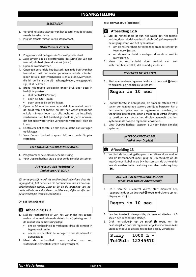
INGANGSTELLING
NL - Nederlands Pagina 76
ELEKTRISCH
1. Verbind het aansluitsnoer van het toestel met de uitgang
van de transformator. 2. Plug de transformator in een stopcontact.
ONDER DRUK ZETTEN 1. Zorg ervoor dat de bypass in 'bypass' positie staat. 2. Zorg ervoor dat de elektronische besturing(en) van het
toestel(s) in bedrijfsmodus staat (staan). 3. Open de watertoevoer. 4. Open een behandeld koudwaterkraan in de buurt van het
toestel en laat het water gedurende enkele minuten lopen tot alle lucht verdwenen is en alle onzuiverheden, die bij de installatie zijn achtergebleven, weggespoeld zijn; sluit de kraan.
5. Breng het toestel geleidelijk onder druk door deze in bedrijf te plaatsen:
• sluit de 'BYPASS' kraan;
• open de 'OUT' kraan;
• open geleidelijk de 'IN' kraan. 6. Open na 2-3 minuten een behandeld koudwaterkraan in
de buurt van het toestel en laat het water gedurende enkele minuten lopen tot alle lucht uit de installatie verdwenen is en het harsbed gespoeld is (het is normaal dat het spoelwater enige verkleuring vertoont!); sluit de kraan.
7. Controleer het toestel en alle hydraulische aansluitingen op lekkages.
8. Voor Duplex: herhaal stappen 5-7 voor beide Simplex systemen.
ELEKTRONISCH BEDIENINGSPANEEL
1. Programmeer de elektronische besturing. 2. Voor Duplex: herhaal stap 1 voor beide Simplex systemen.
AFSTELLING RESTHARDHEID (enkel voor PF-SOF1)
In de praktijk wordt de resthardheid beïnvloed door de ingangsdruk, het debiet en de hardheid van het inkomende onbehandelde water. Zorg er bij de de afstelling van de resthardheid voor dat deze condities vergelijkbaar zijn aan de uiteindelijke werkingsconditions.
OP BESTURINGSKLEP
Afbeelding 12.a
1. Stel de resthardheid af van het water dat het toestel verlaat, door middel van de afstelschroef, geïntegreerd in de zijkant van de besturingsklep:
• om de resthardheid te verhogen: draai de schroef in tegenuurwijzerzin.
• om de resthardheid te verlagen: draai de schroef in uurwijzerzin.
2. Meet de resthardheid door middel van een waterhardheidstestkit; stel zo nodig verder af.
MET BYPASSBLOK (optioneel)
Afbeelding 12.b
1. Stel de resthardheid af van het water dat het toestel verlaat, door middel van de afstelschroef, geïntegreerd in de uitgangskraan van het bypassblok:
• om de resthardheid te verhogen: draai de schroef in tegenuurwijzerzin.
• om de resthardheid te verlagen: draai de schroef in uurwijzerzin.
2. Meet de resthardheid door middel van een waterhardheidstestkit; stel zo nodig verder af.
REGENERATIE STARTEN
1. Start manueel een regeneratie door op de scroll toets
te drukken; op het display verschijnt: 2. Laat het toestel in deze positie; de timer zal aftellen tot 0
sec en een regeneratie starten; om tijd te besparen kan u de tweede cyclus van de regeneratie overslaan, of vroegtijdig beëindigen, door 1 maal op de scroll toets te drukken, van zodra het display aangeeft dat het systeem in de tweede regeneratiepositie is.
3. Voor Duplex: herhaal stappen 1-2 voor beide Simplex systemen.
INTERCONNECT-KABEL
(enkel voor Duplex)
Afbeelding 13
1. Verbind de besturingskleppen met elkaar door middel van de InterConnect-kabel; plug de DIN-stekkers op de InterConnect-kabel in de DIN-bussen aan de achterzijde van de elektronische besturing van elke besturingsklep ().
ACTIVEER ALTERNERENDE MODUS (enkel voor Duplex Alternerend)
1. Op 1 van de 2 control valves, start manueel een
regeneratie door op de scroll toets te drukken; op het display verschijnt:
2. Laat het toestel in deze positie; de timer zal aftellen tot 0
sec en een regeneratie starten. 3. Druk herhaaldelijk op de scroll toets, om de
besturingsklep door de regeneratiecycli te voeren en ze in Standby modus te zetten, tot op het display verschijnt:
Regen in 10 sec
Regen in 10 sec
Stdby 1000 L -
TotVol: 1234567L

ELEKTRONISCH BEDIENINGSPANEEL
Pagina 77 NL - Nederlands
Afbeelding 14
symbool toets functie
SCROLL om verder te gaan naar de
volgende parameter
UP om de waarde van de
parameter te verhogen
DOWN om de waarde van de parameter te verlagen
OPSTART
Na de opstart zal het display de geïnstalleerde softwareversie tonen gedurende 5 sec.
STROOMONDERBREKING
I.g.v. een stroomonderbreking zal het programma voor onbepaalde tijd in het NOVRAM® opgeslagen worden, terwijl een ingebouwde SuperCap (condensator) het juiste uur van de dag zal behouden gedurende meerdere uren; dientengevolge is het mogelijk dat i.g.v. een langdurige stroomonderbreking, het uur van de dag niet bijgehouden wordt; wanneer dit gebeurt, zal, wanneer de stroomtoevoer hersteld is, de aanduiding van het uur van de dag knipperen, hetgeen betekent dat het uur van de dag opnieuw ingesteld dient te worden. Wanneer een stroomonderbreking zich voordoet tijdens de uitvoering van een automatische regeneratie, zal de besturingsklep in zijn laatste positie blijven staan; wanneer de stroomtoevoer hersteld is, zal de besturingsklep terugkeren naar de servicepositie, daar gedurende 60 sec. blijven staan en opnieuw een volledige regeneratie starten van bij het begin.
STORING BESTURING
I.g.v. een storing van de besturing, zal de volgende melding op het display verschijnen:
De buzzer zal, indien geactiveerd (zie Basisinstellingen), herhaaldelijk een hoorbaar signaal uitzenden. Indien het heropstarten van het toestel dit probleem niet verhelpt, dient professionele bijstand ingeroepen te worden.
ONDERHOUDSMELDING
Enkel beschikbaar indien de onderhoudsmeldingsfunctie geactiveerd en geprogrammeerd werd door uw leverancier!
Van zodra het onderhoudsinterval bereikt is, zal het volgende verschijnen: 1. het display zal afwisselend de volgende melding tonen:
2. de buzzer zal, indien geactiveerd (zie Basisinstellingen), elk uur 3 maal een hoorbaar signaal uitzenden.
Alhoewel het toestel normaal zal blijven functioneren, is het raadzaam om preventief onderhoud te laten uitvoeren door een vakman.
BEDRIJFSMODUS
In bedrijfsmodus toont het display:
• Simplex, Duplex Parallel: het uur v.d. dag en de resterende capaciteit:
• Duplex Alternerend: de status van het systeem (Service of Standby) en de resterende capaciteit:
REGENERATIEMODUS
In regeneratiemodus toont het display:
• Simplex, Duplex Parallel: de totale resterende duur van de regeneratie en de resterende duur van de cyclus:
• Duplex Alternerend: de totale resterende duur van de regeneratie en de resterende duur van de cyclus:
Wanneer de regeneratie beëindigd is, blijft het systeem in Standby, tot het andere systeem een regeneratie start:
Het toestel kan ten allen tijde naar de bedrijfsmodus teruggesteld worden door op de scroll toets te drukken, waardoor het toestel manueel door de regeneratiecycli gevoerd wordt.
MANUELE REGENERATIE
Het is mogelijk om manueel een onmiddellijke regeneratie of een uitgestelde regeneratie (op het voorgeprogrammeerde uur van regeneratie) te starten. 1. Druk op de scroll toets; op het display verschijnt:
• Indien het bedieningspaneel in deze positie gelaten wordt, zal de countdown teller tot 0 sec aftellen en een onmiddellijke regeneratie starten.
Rgn:XXX CycY:ZZZ
8:01 1000L –
TotVol: 1234567L
Rgn:XXX CycY:ZZZ
Srvc 1000L –
TotVol: 1234567L
Stdby 1000L –
TotVol: 1234567L
Stdby 1000L –
TotVol: 1234567L
Regen in 10 sec
8:01 1000L –
Onderhoud Nu
Service vereist

ELEKTRONISCH BEDIENINGSPANEEL
NL - Nederlands Pagina 78
• Druk op de scroll toets alvorens de countdown teller 0 sec heeft bereikt, om deze modus te annuleren; op het display verschijnt:
• Indien het bedieningspaneel in deze positie gelaten wordt, zal een uitgestelde regeneratie gestart worden op het aangegeven voorgeprogrammeerde uur van regeneratie.
• Druk op de scroll toets om deze modus te annuleren; het bedieningspaneel zal terugkeren naar de bedrijfsmodus.
VAKANTIEMODUS
Het is mogelijk om het toestel in vakantiemodus te plaatsen; dit zal voorkomen dat automatische regeneratie plaatsvindt, maar zal ervoor zorgen dat het toestel automatisch geregenereerd wordt op het einde van de vakantiecyclus. 1. Druk herhaaldelijk op de scroll toets tot op het display
verschijnt:
• Druk op de op of neer toets om de vakantiemodus te activeren door het aantal volledige dagen weg van huis in te stellen, of de vakantiemodus te desactiveren (OFF).
Van zodra het bedieningspaneel terug in bedrijfsmodus staat, verschijnt op het display:
De vakantiemodus wordt automatisch geannuleerd van zodra manueel een regeneratie gestart wordt!
PROGRAMMEERINSTRUCTIES - BASISINSTELLINGEN
Alvorens in het programmeerniveau te gaan, zorg ervoor dat het toestel zich in de bedrijfsmodus bevindt.
Indien in een tijdspanne van 5 min niet op een van de toetsen gedrukt wordt, zal het bedieningspaneel automatisch terugkeren naar de bedrijfsmodus; eventueel aangebrachte wijzigingen zullen NIET opgeslagen worden!
1. Druk op de scroll toets en houdt deze 2 sec ingedrukt
tot op het display verschijnt:
• Druk op de op of neer toets om de taal in te stellen.
2. Druk nogmaals op de scroll toets; op het display
verschijnt:
• Druk op de op of neer toets om het uur v.d. dag in te stellen.
3. Druk nogmaals op de scroll toets; op het display
verschijnt:
• Druk op de op of neer toets om de meeteenheid van waterhardheid in te stellen. Zorg ervoor dat deze identiek is aan de meeteenheid van de waterhardheidstestkit of wateranalyseverslag, dat gebruikt wordt om de hardheid van het inkomende onbehandelde water vast te stellen!
4. Druk nogmaals op de scroll toets; op het display
verschijnt:
• Druk op de op of neer toets om de hardheid van het inkomende onbehandelde water in te stellen.
5. Druk nogmaals op de scroll toets; op het display
verschijnt:
• Druk op de op of neer toets om de buzzer te activeren of te desactiveren.
Regen @ 2:00
Vakantie:OFF
8:01 Vakantie
Taal: Nederlands
Klok: 8:01
Hard. eenh.: °f
Hardheid: XX °f
Buzzer: ON

ELEKTRONISCH BEDIENINGSPANEEL
Pagina 79 NL - Nederlands
6. Druk nogmaals op de scroll toets; op het display verschijnt:
• Druk op de op of neer toets om het programma op te slaan in het NOVRAM® en het programmeerniveau te verlaten.
PROGRAMMEERINSTRUCTIES - CONFGURATIEPARAMETERS
Alvorens in het programmeerniveau te gaan, zorg ervoor dat het toestel zich in de bedrijfsmodus bevindt.
Alle configuratieparameters van dit toestel zijn voorgeprogrammeerd in de fabriek, teneinde optimale prestaties te bieden in een verscheidenheid aan toepassingen en situaties. Het kan soms noodzakelijk of wenselijk zijn één van deze parameters te wijzigen, om de prestaties van het toestel verder te optimaliseren of om het aan te passen aan de specifieke vereisten van de installatie.
Indien in een tijdspanne van 5 min niet op een van de toetsen gedrukt wordt, zal het bedieningspaneel automatisch terugkeren naar de bedrijfsmodus; eventueel aangebrachte wijzigingen zullen NIET opgeslagen worden!
enkel voor PF-SOF1-SIM & PF-SOF1,5-SIM
1. Druk op de scroll toets en houdt hem 6 sec. ingedrukt
tot op het display verschijnt: 2. Binnen 10 sec, druk op de op toets; op het display
verschijnt:
• Druk op de op of neer toets om de meeteenheid in te stellen (Metrisch of Engels-US).
3. Druk nogmaals op de scroll toets; op het display verschijnt:
• Druk op de op of neer toets om de onderhoudsherinnering te activeren door de onderhoudsinterval in te stellen of om de onderhoudsherinnering uit te schakelen.
4. Druk nogmaals op de scroll toets; op het display
verschijnt:
• Druk op de op of neer toets om de uitwisselingscapaciteit per liter hars in te stellen.
5. Druk nogmaals op de scroll toets; op het display
verschijnt:
• Druk op de op of neer toets om de leeftijd correctiefactor (%/jaar) in te stellen ter compensatie van de veroudering van het hars.
ExCap:5.5°f M3/L
System Check
Eenh.:Metrisch
Ondrh.Int:24 mnd
Oud.Corr.: 2.0%
Verlaten

ELEKTRONISCH BEDIENINGSPANEEL
NL - Nederlands Pagina 80
6. Druk nogmaals op de scroll toets; op het display verschijnt:
• Druk op de op of neer toets om het harsvolume in te stellen.
7. Druk nogmaals op de scroll toets; op het display
verschijnt:
• Druk op de op of neer toets om het aantal dagen tussen regeneraties in te stellen.
8. Druk nogmaals op de scroll toets; op het display
verschijnt:
• Druk op de op of neer toets om de lengte van de regeneratiecyclus in te stellen.
• Druk nogmaals op de scroll toets om verder te gaan naar de volgende regeneratiecyclus.
Cycle 1 Terugspoelen
Cycle 2 Pekel zuigen/traag spoelen
Cycle 3 Snel spoelen/pekelbak vullen (PF-SOF1) Snel spoelen (PF-SOF1,5)
Cycle 4 Pekelbak vullen (PF-SOF1,5)
9. Druk nogmaals op de scroll toets; op het display
verschijnt:
• Druk op de op of neer toets om de regeneratiemodus in te stellen:
Uitgest/Onm: zodra de restcapaciteit gelijk wordt aan de reservecapaciteit, wordt een uitgestelde regeneratie gestart op het geprogrammeerde uur van regeneratie; wanneer de restcapaciteit echter gelijk wordt aan 0 alvorens het geprogrammeerde uur van regeneratie bereikt is, wordt een onmiddellijke regeneratie gestart.
Onmiddellijk: zodra de restcapaciteit 0 bereikt, wordt een onmiddellijke regeneratie gestart. Opmerking: Uitgestelde Manuele Regeneratie is niet beschikbaar wanneer deze regeneratiemodus is geselecteerd.
Uitgesteld: zodra de restcapaciteit gelijk wordt aan de reservecapaciteit, wordt een uitgestelde regeneratie op het geprogrammeerde uur van regeneratie gestart.
10. Druk nogmaals op de scroll toets; op het display verschijnt (enkel indien regeneratiemodus ingesteld is op 'Uitgesteld' of 'Uitgest/Onm'):
• Druk op de op of neer toets om het uur van regeneratie in te stellen.
11. Druk nogmaals op de scroll toets; op het display
verschijnt (enkel indien regeneratiemodus ingesteld is op 'Uitgesteld' of 'Uitgest/Onm'):
• Druk op de op of neer toets om de reservecapaciteit in te stellen:
Variabele: de reservecapaciteit wordt automatisch berekend, op basis van het geregistreerde dagelijks waterverbruik.
Fix: druk op de op of neer toets om de reservecapaciteit vast in te stellen.
12. Druk nogmaals op de scroll toets; op het display
verschijnt:
• Druk op de op of neer toets om de functie van het hulpcontact in te stellen:
Regen: aux. contact wordt ingeschakeld tijdens de volledige regeneratie (uitgezonderd tijdens het vullen van de pekelbak en de pekelbereiding!).
Chlor.Cell: aux. contact wordt ingeschakeld bij het begin van de pekelopzuiging/traag spoelen. Druk nogmaals op de scroll toets en druk op de op
of neer toets om de bekrachtingsduur van de chlorinatie cel in te stellen.
Maintenance: aux. contact wordt ingeschakeld als een onderhoudsherinnering wordt geactiveerd.
Error: aux. contact wordt ingeschakeld bij een storing van de besturing.
13. Druk nogmaals op de scroll toets; op het display
verschijnt:
• Druk op de op of neer toets om het programma op te slaan in het NOVRAM® en het programmeerniveau te verlaten.
Cycle 1: XX min
Regen @ 2:00
Verlaten
Hars:XXX Ltr
Override: 7dagen
Rgn:Uitgest/Onm
Rsrv Variabele
AUX2: Regen
ELEKTRONISCH BEDIENINGSPANEEL
Pagina 81 NL - Nederlands
enkel voor PF-SOF1-ALT & PF-SOF1,5-ALT
Elk van de 2 Simplex systemen, die samen een Duplex systeem vormen, dient individueel geprogrammeerd te worden; het programma dient NIET noodzakelijkerwijze hetzelfde te zijn voor beide Simplex systemen!
1. Druk op de scroll toets en houdt hem 6 sec. ingedrukt
tot op het display verschijnt: 2. Binnen 10 sec, druk op de op toets; op het display
verschijnt:
• Druk op de op of neer toets om de meeteenheid in te stellen (Metrisch of Engels-US).
3. Druk nogmaals op de scroll toets; op het display verschijnt:
• Druk op de op of neer toets om de onderhoudsherinnering te activeren door de onderhoudsinterval in te stellen of om de onderhoudsherinnering uit te schakelen.
4. Druk nogmaals op de scroll toets; op het display
verschijnt:
• Druk op de op of neer toets om de uitwisselingscapaciteit per liter hars in te stellen.
5. Druk nogmaals op de scroll toets; op het display
verschijnt:
• Druk op de op of neer toets om de leeftijd correctiefactor (%/jaar) in te stellen ter compensatie van de veroudering van het hars.
6. Druk nogmaals op de scroll toets; op het display
verschijnt:
• Druk op de op of neer toets om het harsvolume in te stellen.
7. Druk nogmaals op de scroll toets; op het display verschijnt:
• Druk op de op of neer toets om het aantal dagen tussen regeneraties in te stellen.
8. Druk nogmaals op de scroll toets; op het display
verschijnt:
• Druk op de op of neer toets om de lengte van de regeneratiecyclus in te stellen.
• Druk nogmaals op de scroll toets om verder te gaan naar de volgende regeneratiecyclus.
Cyclus 1 Terugspoelen
Cyclus 2 Pekel zuigen/traag spoelen
Cyclus 3 Snel spoelen/pekelbak vullen (PF-SOF1) Snel spoelen (PF-SOF1,5)
Cyclus 4 Pekelbak vullen (PF-SOF1,5)
9. Druk nogmaals op de scroll toets; op het display
verschijnt:
• Druk op de op of neer toets om de functie van het hulpcontact in te stellen:
Regen: aux. contact wordt ingeschakeld tijdens de volledige regeneratie (uitgezonderd tijdens het vullen van de pekelbak en de pekelbereiding!).
Chlor.Cell: aux. contact wordt ingeschakeld bij het begin van de pekelopzuiging/traag spoelen. Druk nogmaals op de scroll toets en druk op de op
of neer toets om de bekrachtingsduur van de chlorinatie cel in te stellen.
Maintenance: aux. contact wordt ingeschakeld als een onderhoudsherinnering wordt geactiveerd.
Error: aux. contact wordt ingeschakeld bij een storing van de besturing.
10. Druk nogmaals op de scroll toets; op het display
verschijnt:
• Druk op de op of neer toets om het programma op te slaan in het NOVRAM® en het programmeerniveau te verlaten.
11. Herhaal stappen 1-10 voor beide Simplex systemen.
Verlaten
Cycle 1: XX min
Hars:XXX Ltr
ExCap:5.5°f M3/L
System Check
Eenh.:Metrisch
Ondrh.Int:24 mnd
Oud.Corr.: 2.0%
Override: 7dagen
AUX2: Regen

ELEKTRONISCH BEDIENINGSPANEEL
NL - Nederlands Pagina 82
enkel voor PF-SOF1-PRL & PF-SOF1,5-PRL
Elk van de 2 Simplex systemen, die samen een Duplex systeem vormen, dient individueel geprogrammeerd te worden; het programma dient NIET noodzakelijkerwijze hetzelfde te zijn voor beide Simplex systemen!
1. Druk op de scroll toets en houdt hem 6 sec. ingedrukt
tot op het display verschijnt: 2. Binnen 10 sec, druk op de op toets; op het display
verschijnt:
• Druk op de op of neer toets om de meeteenheid in te stellen (Metrisch of Engels-US).
3. Druk nogmaals op de scroll toets; op het display verschijnt:
• Druk op de op of neer toets om de onderhoudsherinnering te activeren door de onderhoudsinterval in te stellen of om de onderhoudsherinnering uit te schakelen.
4. Druk nogmaals op de scroll toets; op het display
verschijnt:
• Druk op de op of neer toets om de uitwisselingscapaciteit per liter hars in te stellen.
5. Druk nogmaals op de scroll toets; op het display
verschijnt:
• Druk op de op of neer toets om de leeftijd correctiefactor (%/jaar) in te stellen ter compensatie van de veroudering van het hars.
6. Druk nogmaals op de scroll toets; op het display
verschijnt:
• Druk op de op of neer toets om het harsvolume in te stellen.
7. Druk nogmaals op de scroll toets; op het display verschijnt:
• Druk op de op of neer toets om het aantal dagen tussen regeneraties in te stellen.
8. Druk nogmaals op de scroll toets; op het display
verschijnt:
• Druk op de op of neer toets om de lengte van de regeneratiecyclus in te stellen.
• Druk nogmaals op de scroll toets om verder te gaan naar de volgende regeneratiecyclus.
Cyclus 1 Terugspoelen
Cyclus 2 Pekel zuigen/traag spoelen
Cyclus 3 Snel spoelen/pekel bakvullen (PF-SOF1) Snel spoelen (PF-SOF1,5)
Cyclus 4 Pekelbak vullen (PF-SOF1,5)
9. Druk nogmaals op de scroll toets; op het display
verschijnt:
• Druk op de op of neer toets om de regeneratiemodus in te stellen:
Onmiddellijk: zodra de restcapaciteit 0 bereikt, wordt een onmiddellijke regeneratie gestart. Opmerking: Uitgestelde Manuele Regeneratie is niet beschikbaar wanneer deze regeneratiemodus is geselecteerd.
Uitgest/Onm: zodra de restcapaciteit gelijk wordt aan de reservecapaciteit, wordt een uitgestelde regeneratie gestart op het geprogrammeerde uur van regeneratie; wanneer de restcapaciteit echter gelijk wordt aan 0 alvorens het geprogrammeerde uur van regeneratie bereikt is, wordt een onmiddellijke regeneratie gestart.
Uitgesteld: zodra de restcapaciteit gelijk wordt aan de reservecapaciteit, wordt een uitgestelde regeneratie op het geprogrammeerde uur van regeneratie gestart.
10. Druk nogmaals op de scroll toets; op het display
verschijnt (enkel indien regeneratiemodus ingesteld is op 'Uitgesteld' of 'Uitgest/Onm'):
• Druk op de op of neer toets om het uur van regeneratie in te stellen.
Rgn:Onmiddellijk
Regen @ 2:00
Cycle 1: XX min
Hars:XXX Ltr
ExCap:5.5°f M3/L
Override: 7dagen
System Check
Eenh.:Metrisch
Ondrh.Int:24 mnd
Oud.Corr.: 2.0%

ELEKTRONISCH BEDIENINGSPANEEL
Pagina 83 NL - Nederlands
11. Druk nogmaals op de scroll toets; op het display verschijnt (enkel indien regeneratiemodus ingesteld is op 'Uitgesteld' of 'Uitgest/Onm'):
• Druk op de op of neer toets om de reservecapaciteit in te stellen:
Variabele: de reservecapaciteit wordt automatisch berekend, op basis van het geregistreerde dagelijks waterverbruik.
Fix: druk op de op of neer toets om de reservecapaciteit vast in te stellen.
12. Druk nogmaals op de scroll toets; op het display
verschijnt:
• Druk op de op of neer toets om de functie van het hulpcontact in te stellen:
Regen: aux. contact wordt ingeschakeld tijdens de volledige regeneratie (uitgezonderd tijdens het vullen van de pekelbak en de pekelbereiding!).
Chlor.Cell: aux. contact wordt ingeschakeld bij het begin van de pekelopzuiging/traag spoelen. Druk nogmaals op de scroll toets en druk op de op
of neer toets om de bekrachtingsduur van de chlorinatie cel in te stellen.
Maintenance: aux. contact wordt ingeschakeld als een onderhoudsherinnering wordt geactiveerd.
Error: aux. contact wordt ingeschakeld bij een storing van de besturing.
13. Druk nogmaals op de scroll toets; op het display
verschijnt:
• Druk op de op of neer toets om het programma op te slaan in het NOVRAM® en het programmeerniveau te verlaten.
14. Herhaal stappen 1-13 voor beide Simplex systemen.
Rsrv Variabele
Verlaten
AUX2: Regen

ONDERHOUD
NL - Nederlands Pagina 84
AANBEVELING
Niettegenstaande de betrouwbaarheid van het toestel, raden wij ten sterkste aan het op regelmatige basis te laten nakijken en onderhouden door een bevoegd en naar behoren geschoold technieker. Hij zal in staat zijn het gepaste onderhoudsinterval voor het toestel te bepalen, afhankelijk van de specifieke toepassing en de plaatselijke werkomstandigheden. De voordelen van het regelmatig uitvoeren van onderhoud:
• regelmatige controle van de plaatselijke werkomstandigheden (kwaliteit van het water, druk, etc);
• regelmatig nazicht en aanpassing van de instellingen van het apparaat, om te garanderen dat het werkt met maximale efficiëntie;
• minimaliseren van het risico op onverwachte uitval. Neem contact op met uw dealer of installateur voor meer informatie, of bezoek onze website.
REGELMATIGE CONTROLEPUNTEN
De gebruiker dient regelmatig een basiscontrole uit te voeren op de correcte werking van het toestel, aan de hand van de volgende controlepunten: 1. Verifieer instellingen van elektronisch bedieningspaneel. 2. Meet waterhardheid voor/na toestel. 3. Verifieer rioolslang van besturingsklep; er mag geen
wateruitstroming zijn (tenzij toestel in regeneratie is). 4. Verifieer rioolslang van pekelbakoverloopelleboog; er
mag geen wateruitstroming zijn. 5. Verifieer toestel en omliggende zone; er mogen geen
waterlekkages zijn.
BYPASSEN VAN HET TOESTEL
Occasioneel kan het nodig zijn om het toestel hydraulisch in bypass te zetten, i.e. om deze te isoleren van het waterleidingnetwerk; bijv.:
• i.g.v. een dringend technisch probleem;
• wanneer het niet nodig is behandeld water te leveren aan de toepassing.
MET BYPASSBLOK (optioneel)
Afbeelding 15.a
BEDRIJFSPOSITIE = ingangskraan naar het toestel is OPEN ❖ = uitgangskraan weg van het toestel is OPEN
Afbeelding 15.b
BYPASSPOSITIE = ingangskraan naar het toestel is TOE ❖ = uitgangskraan weg van het toestel is TOE
Afbeelding 15.c
ONDERHOUDSPOSITIE = ingangskraan naar het toestel is OPEN ❖ = uitgangskraan weg van het toestel is TOE
REGENERATIEZOUT
Het toestel heeft 'pekel' nodig voor zijn periodieke regeneraties. Deze pekeloplossing wordt aangemaakt met water, dat automatisch naar de pekelbak gedoseerd wordt door de besturingsklep, en regeneratiezout. De gebruiker dient ervoor te zorgen dat er ten allen tijde voldoende regeneratiezout in de pekelbak is. Daarom dient het zoutniveau regelmatig nagekeken en indien nodig bijgevuld te worden. Het opheffen van het deksel van de pekelbak volstaat om het zoutniveau in de pekelbak na te kijken. Idealiter wordt het zoutniveau in de pekelbak tussen 1/3 en 2/3 gehouden. Een lager zoutniveau kan leiden tot onvoldoende verzadigde pekel, wat resulteert in een verlies aan onthardingscapaciteit. Een hoger zoutniveau kan leiden tot het samenklitten van het zout (harde korst of zoutklonters in het pekelkabinet). Wanneer u meent dat er zich zoutklonters gevormd hebben:
• sla zachtjes op de buitenkant van de pekelbak;
• duw m.b.v. een borstelsteel (of ander stomp voorwerp) voorzichtig op het zout om het los te breken;
• giet warm water over het zout om het op te lossen.
HARSREINIGER
Andere onzuiverheden (bijv. ijzer) die zich in het water bevinden, kunnen het harsbed bevuilen, wat resulteert in een verlies aan onthardingscapaciteit. Periodiek kan een goedgekeurde harsreiniger gebruikt worden om het harsbed diepgaand schoon te maken.
ZUIVERMAKEN VAN HET TOESTEL
Dit toestel is opgebouwd uit kwaliteitsmaterialen en geassembleerd in veilige omstandigheden om ervoor te zorgen dat hij schoon en zuiver is. Indien correct geïnstalleerd en onderhouden, zal dit toestel uw water niet vervuilen of besmetten. Desalniettemin, net zoals in elk toestel dat in uw waterleidingnetwerk geïnstalleerd is, is een proliferatie van bacteriën mogelijk, zeker in geval van 'stilstaand water'. Daarom is dit toestel uitgerust met een ‘days override’ functie, die het harsbed automatisch periodiek zal spoelen, zelfs in geval van een beperkt of totaal ontbreken van waterverbruik. Indien de stroomtoevoer van het toestel gedurende een lange periode onderbroken geweest is, raden wij aan om, wanneer de stroomtoevoer hersteld is, manueel een regeneratie te starten.
NORMAAL GESLOTEN SERVICEKLEPPEN (enkel voor PF-SOF1-ALT & PF-SOF1,5-ALT)
Afbeelding 16
= automatisch bediend = normaal gesloten ❖ = manueel bediend = constant open De Normaal Gesloten Serviceklep in de uitgang van elk Simplex systeem zal enkel geopend worden wanneer ze bekrachtigd wordt. Om de Normaal Gesloten Serviceklep te openen (bijv. i.g.v. een stroomonderbreking), draai gewoon de witte magneetspoel in tegenuurwijzerzin.
SAMENSTELLINGSOVERZICHT
Pagina 85 NL - Nederlands
Model Hars
volume PN
Besturingsklep, incl. transformator, 1” BSP Mann. aansluitingen
InterConnect kabel
Serviceklep 1” BSP Vrouw.
Druktank, incl. verdelersysteem
Hars (zak 25 ltr)
ltr model # # model # model # #
PF-
SOF1
-SIM
25 35810 2400VS/J4JB/PRL1 1 0 / 0 10x35 1 1
50 35811 2400VS/J1KD/PRL1 1 0 / 0 12x48 1 2
75 35812 2400VS/J1LD/PRL1 1 0 / 0 13x54 1 3
100 35813 2400VS/J2MD/PRL1 1 0 / 0 14x65 1 4
150 35814 2400VS/J2ND/PRL1 1 0 / 0 16x65 1 6
PF-
SOF1
-ALT
2 x 25 35815 2400VS/J4JB/ALT 2 1 NC (1) 2 10x35 2 2
2 x 50 35816 2400VS/J1KD/ALT 2 1 NC (1) 2 12x48 2 4
2 x 75 35817 2400VS/J1LD/ALT 2 1 NC (1) 2 13x54 2 6
2 x 100 35818 2400VS/J2MD/ALT 2 1 NC (1) 2 14x65 2 8
2 x 150 35819 2400VS/J2ND/ALT 2 1 NC (1) 2 16x65 2 12
PF-
SOF1
-PR
L
2 x 25 35820 2400VS/J4JB/PRL1 2 1 NO (2) 2 10x35 2 2
2 x 50 35821 2400VS/J1KD/PRL1 2 1 NO (2) 2 12x48 2 4
2 x 75 35822 2400VS/J1LD/PRL1 2 1 NO (2) 2 13x54 2 6
2 x 100 35823 2400VS/J2MD/PRL1 2 1 NO (2) 2 14x65 2 8
2 x 150 35824 2400VS/J2ND/PRL1 2 1 NO (2) 2 16x65 2 12
(1) NC = Normaal Gesloten (2) NO = Normaal Open
Model Hars
volume PN
Besturingsklep, incl. transformator, 1” BSP Mann. aansluitingen
InterConnect kabel
Serviceklep 1” BSP Vrouw.
Druktank, incl. verdelersysteem
Hars (zak 25 ltr)
ltr model # # model # model # #
PF-
SOF1
,5-S
IM
75 35825 EV1.5VS/J/5A/40/12 1 0 / 0 13x54 1 3
100 35826 EV1.5VS/J/5A/50/12 1 0 / 0 14x65 1 4
150 35827 EV1.5VS/J/5A/60/12 1 0 / 0 16x65 1 6
200 35828 EV1.5VS/J/5/80/20 1 0 / 0 18x65 1 8
250 35829 EV1.5VS/J/5/100/20 1 0 / 0 21x62 1 10
350 35830 EV1.5VS/J/6/150/20 1 0 / 0 24x72 1 14
500 35831 EV1.5VS/J/6/200/20 1 0 / 0 30x72 1 20
PF-
SOF1
,5-A
LT
2 x 75 35832 EV1.5VS/J/5A/40/12/ALT 2 1 NC (1) 2 13x54 2 6
2 x 100 35833 EV1.5VS/J/5A/50/12/ALT 2 1 NC (1) 2 14x65 2 8
2 x 150 35834 EV1.5VS/J/5A/60/12/ALT 2 1 NC (1) 2 16x65 2 12
2 x 200 35835 EV1.5VS/J/5/80/20/ALT 2 1 NC (1) 2 18x65 2 16
2 x 250 35836 EV1.5VS/J/5/100/20/ALT 2 1 NC (1) 2 21x62 2 20
2 x 350 35837 EV1.5VS/J/6/150/20/ALT 2 1 NC (1) 2 24x72 2 28
2 x 500 35838 EV1.5VS/J/6/200/20/ALT 2 1 NC (1) 2 30x72 2 40
PF-
SOF1
,5-P
RL
2 x 75 35839 EV1.5VS/J/5A/40/12 2 1 NO (2) 2 13x54 2 6
2 x 100 35840 EV1.5VS/J/5A/50/12 2 1 NO (2) 2 14x65 2 8
2 x 150 35841 EV1.5VS/J/5A/60/12 2 1 NO (2) 2 16x65 2 12
2 x 200 35842 EV1.5VS/J/5/80/20 2 1 NO (2) 2 18x65 2 16
2 x 250 35843 EV1.5VS/J/5/100/20 2 1 NO (2) 2 21x62 2 20
2 x 350 35844 EV1.5VS/J/6/150/20 2 1 NO (2) 2 24x72 2 28
2 x 500 35845 EV1.5VS/J/6/200/20 2 1 NO (2) 2 30x72 2 40
(1) NC = Normaal Gesloten (2) NO = Normaal Open
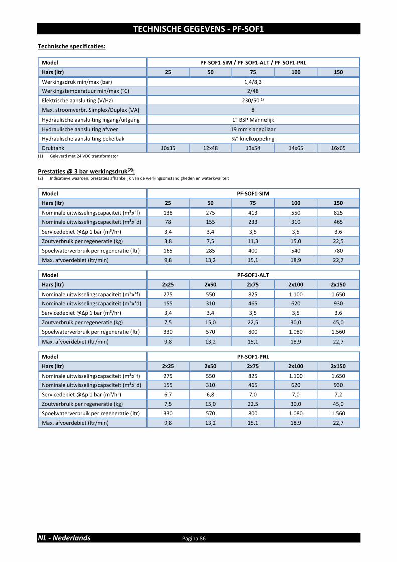
TECHNISCHE GEGEVENS - PF-SOF1
NL - Nederlands Pagina 86
Technische specificaties:
(1) Geleverd met 24 VDC transformator
Prestaties @ 3 bar werkingsdruk(2): (2) Indicatieve waarden, prestaties afhankelijk van de werkingsomstandigheden en waterkwaliteit
Model PF-SOF1-SIM / PF-SOF1-ALT / PF-SOF1-PRL
Hars (ltr) 25 50 75 100 150
Werkingsdruk min/max (bar) 1,4/8,3
Werkingstemperatuur min/max (°C) 2/48
Elektrische aansluiting (V/Hz) 230/50(1)
Max. stroomverbr. Simplex/Duplex (VA) 8
Hydraulische aansluiting ingang/uitgang 1” BSP Mannelijk
Hydraulische aansluiting afvoer 19 mm slangpilaar
Hydraulische aansluiting pekelbak ⅜” knelkoppeling
Druktank 10x35 12x48 13x54 14x65 16x65
Model PF-SOF1-SIM
Hars (ltr) 25 50 75 100 150
Nominale uitwisselingscapaciteit (m³x°f) 138 275 413 550 825
Nominale uitwisselingscapaciteit (m³x°d) 78 155 233 310 465
Servicedebiet @∆p 1 bar (m³/hr) 3,4 3,4 3,5 3,5 3,6
Zoutverbruik per regeneratie (kg) 3,8 7,5 11,3 15,0 22,5
Spoelwaterverbruik per regeneratie (ltr) 165 285 400 540 780
Max. afvoerdebiet (ltr/min) 9,8 13,2 15,1 18,9 22,7
Model PF-SOF1-ALT
Hars (ltr) 2x25 2x50 2x75 2x100 2x150
Nominale uitwisselingscapaciteit (m³x°f) 275 550 825 1.100 1.650
Nominale uitwisselingscapaciteit (m³x°d) 155 310 465 620 930
Servicedebiet @∆p 1 bar (m³/hr) 3,4 3,4 3,5 3,5 3,6
Zoutverbruik per regeneratie (kg) 7,5 15,0 22,5 30,0 45,0
Spoelwaterverbruik per regeneratie (ltr) 330 570 800 1.080 1.560
Max. afvoerdebiet (ltr/min) 9,8 13,2 15,1 18,9 22,7
Model PF-SOF1-PRL
Hars (ltr) 2x25 2x50 2x75 2x100 2x150
Nominale uitwisselingscapaciteit (m³x°f) 275 550 825 1.100 1.650
Nominale uitwisselingscapaciteit (m³x°d) 155 310 465 620 930
Servicedebiet @∆p 1 bar (m³/hr) 6,7 6,8 7,0 7,0 7,2
Zoutverbruik per regeneratie (kg) 7,5 15,0 22,5 30,0 45,0
Spoelwaterverbruik per regeneratie (ltr) 330 570 800 1.080 1.560
Max. afvoerdebiet (ltr/min) 9,8 13,2 15,1 18,9 22,7

TECHNISCHE GEGEVENS - PF-SOF1
Pagina 87 NL - Nederlands
Afmetingen:
Model PF-SOF1-SIM
Hars (ltr) 25 50 75 100 150
Breedte (mm) (W) 264 311 338 365 415
Diepte (mm) (D) 282 311 338 365 415
Diepte, incl. bypassblok (mm) (D) 371 376 389 403 428
Hoogte (mm) (H) 1.059 ±10 1.394 ±10 1.560 ±10 1.836 ±10 1.833 ±10
Model PF-SOF1-ALT / PF-SOF1-PRL
Hars (ltr) 2x25 2x50 2x75 2x100 2x150
Breedte (mm) (W) (1) 613 707 761 815 915
Diepte (mm) (D) 405 410 436 463 513
Hoogte (mm) (H) 1.059 ±10 1.394 ±10 1.560 ±10 1.836 ±10 1.833 ±10 (1) Op basis van 85 mm tussenafstand

TECHNISCHE GEGEVENS - PF-SOF1,5
NL - Nederlands Pagina 88
Technische specificaties:
(1) Geleverd met 24 VAC transformator
Prestaties @ 3 bar werkingsdruk(2): (2) Indicatieve waarden, prestaties afhankelijk van de werkingsomstandigheden en waterkwaliteit
Model PF-SOF1,5-SIM / PF-SOF1,5-ALT / PF-SOF1,5-PRL
Hars (ltr) 75 100 150 200 250 350 500
Werkingsdruk min/max (bar) 1,4/8,0
Werkingstemperatuur min/max (°C) 2/48
Elektrische aansluiting (V/Hz) 230/50(1)
Max. stroomverbr. Simplex/Duplex (VA) 80 /2x89
Hydraulische aansluiting ingang/uitgang 1,5” BSP Mannelijk/Vrouwelijk
Hydraulische aansluiting afvoer 1” BSP Mannelijk
Hydraulische aansluiting pekelbak ½” knelkoppeling
Druktank 13x54 14x65 16x65 18x65 21x62 24x72 30x72
Model PF-SOF1,5-SIM
Hars (ltr) 75 100 150 200 250 350 500
Nominale uitwisselingscapaciteit (m³x°f) 413 550 825 1.100 1.375 1.925 2.750
Nominale uitwisselingscapaciteit (m³x°d) 233 310 465 620 775 1.085 1.550
Servicedebiet @∆p 1 bar (m³/hr) 7,8 7,8 7,8 7,9 7,9 8,0 8,0
Zoutverbruik per regeneratie (kg) 11,3 15,0 22,5 30,0 37,5 52,5 75,0
Spoelwaterverbruik per regeneratie (ltr) 469 578 838 1.148 1.435 2.140 3.030
Max. afvoerdebiet (ltr/min) 15,2 19,0 22,7 30,3 37,9 56,8 75,7
Model PF-SOF1,5-ALT
Hars (ltr) 2x75 2x100 2x150 2x200 2x250 2x350 2x500
Nominale uitwisselingscapaciteit (m³x°f) 825 1.100 1.650 2.200 2.750 3.850 5.500
Nominale uitwisselingscapaciteit (m³x°d) 465 620 930 1.240 1.550 2.170 3.100
Servicedebiet @∆p 1 bar (m³/hr) 7,8 7,8 7,8 7,9 7,9 8,0 8,0
Zoutverbruik per regeneratie (kg) 22,5 30,0 45,0 60,0 75,0 105,0 150,0
Spoelwaterverbruik per regeneratie (ltr) 938 1.156 1.676 2.296 2.870 4.280 6.060
Max. afvoerdebiet (ltr/min) 15,2 19,0 22,7 30,3 37,9 56,8 75,7
Model PF-SOF1,5-PRL
Hars (ltr) 2x75 2x100 2x150 2x200 2x250 2x350 2x500
Nominale uitwisselingscapaciteit (m³x°f) 825 1.100 1.650 2.200 2.750 3.850 5.500
Nominale uitwisselingscapaciteit (m³x°d) 465 620 930 1.240 1.550 2.170 3.100
Servicedebiet @∆p 1 bar (m³/hr) 15,6 15,6 15,6 15,8 15,8 16,0 16,0
Zoutverbruik per regeneratie (kg) 22,5 30,0 45,0 60,0 75,0 105,0 150,0
Spoelwaterverbruik per regeneratie (ltr) 938 1.156 1.676 2.296 2.870 4.280 6.060
Max. afvoerdebiet (ltr/min) 15,2 19,0 22,7 30,3 37,9 56,8 75,7
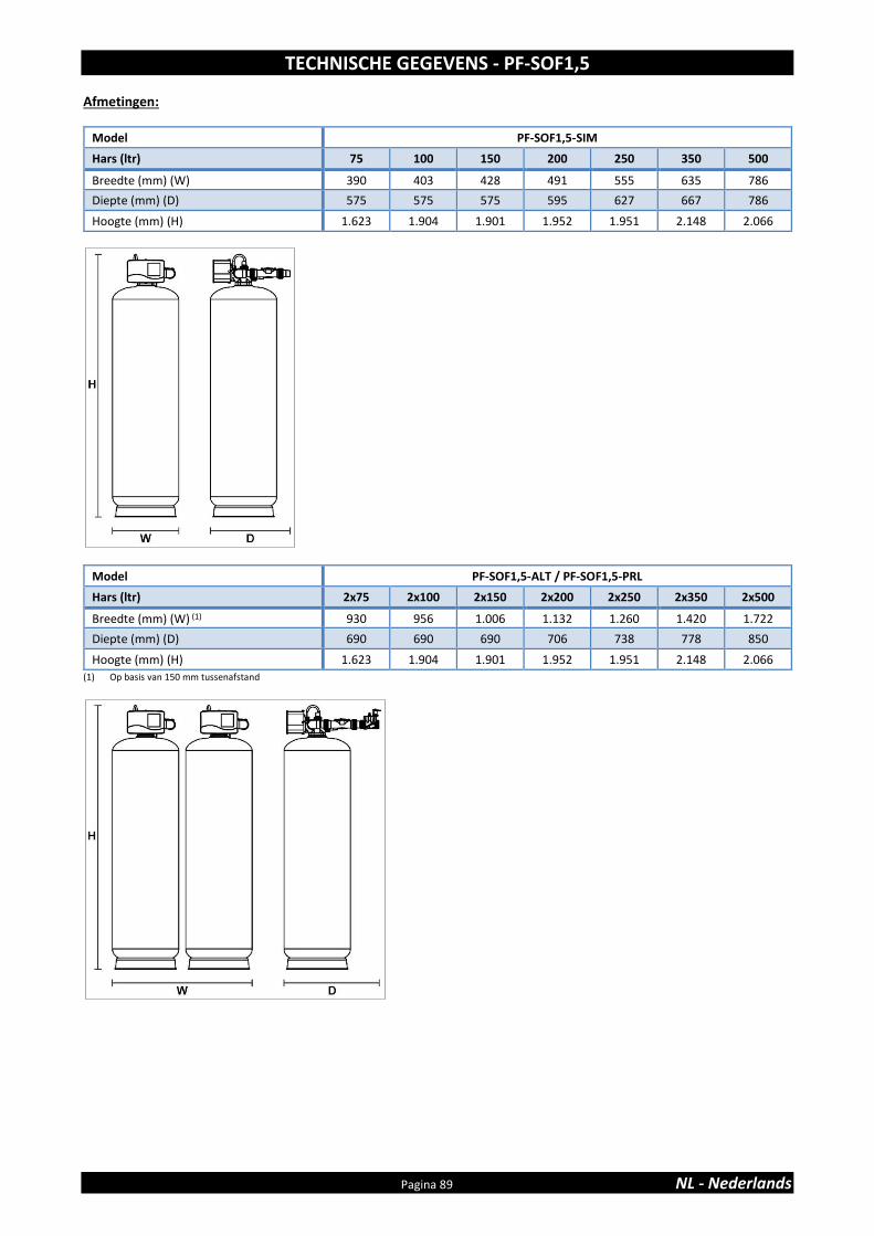
TECHNISCHE GEGEVENS - PF-SOF1,5
Pagina 89 NL - Nederlands
Afmetingen:
Model PF-SOF1,5-SIM
Hars (ltr) 75 100 150 200 250 350 500
Breedte (mm) (W) 390 403 428 491 555 635 786
Diepte (mm) (D) 575 575 575 595 627 667 786
Hoogte (mm) (H) 1.623 1.904 1.901 1.952 1.951 2.148 2.066
(1) Op basis van 150 mm tussenafstand
Model PF-SOF1,5-ALT / PF-SOF1,5-PRL
Hars (ltr) 2x75 2x100 2x150 2x200 2x250 2x350 2x500
Breedte (mm) (W) (1) 930 956 1.006 1.132 1.260 1.420 1.722
Diepte (mm) (D) 690 690 690 706 738 778 850
Hoogte (mm) (H) 1.623 1.904 1.901 1.952 1.951 2.148 2.066

TECHNISCHE GEGEVENS - PF-BTA
NL - Nederlands Pagina 90
Technische specificaties:
Model PF-BTA
Volume (ltr) 125 275 500 750
Hydraulische aansluiting pekelklep uitwisselbaar: ⅜” Quick-Fit & ½” knelkoppeling
Hydraulische aansluiting overloop 19 mm slangpilaar
Afmetingen:
Model PF-BTA
Volume (ltr) 125 275 500 750
Diameter (mm) (D) 540 685 875 1.030
Hoogte (mm) (H) 850 975 1.110 1.110
Hoogte overloop (mm) (H1) 660 825 945 945
Max. zoutopslagcapaciteit (kg) 100 200 475 700

TABLE DE CONTENIDOS Y REGISTRO DE LA INSTALACIÓN
Página 91 ES - Español
Tabla de contenidos y Registro de la instalación ................................................................ Página 91
Advertencias e Instrucciones de seguridad ........................................................................ Página 92
Condiciones y Requisitos de funcionamiento ..................................................................... Página 93
Montaje ............................................................................................................................... Página 94
Instalación ........................................................................................................................... Página 96
Puesta en marcha ................................................................................................................ Página 98
Panel del control electrónico .............................................................................................. Página 99
Mantenimiento ................................................................................................................... Página 106
Lista de composición ........................................................................................................... Página 107
Datos técnicos - PF-SOF1 .................................................................................................... Página 108
Datos técnicos - PF-SOF1,5 ................................................................................................. Página 110
Datos técnicos - PF-BTA ...................................................................................................... Página 112
Para disponer de una referencia, llenar los siguientes datos
REGISTRO DE LA INSTALACIÓN
Numero de serie: ____________________________________________
Modelo: _______________________________________________________ Dureza del agua-entrada: ___________________________________ Dureza del agua-salida: ______________________________________ Presión del agua-entrada: ___________________________________
Fecha de instalación: ________________________________________
Empresa: ______________________________________________________
Instalador: ____________________________________________________ Número de tel.: ______________________________________________

ADVERTENCIAS E INSTRUCCIONES DE SEGURIDAD
ES - Español Página 92
• Antes de comenzar la instalación del aparato, le aconsejamos que lea y siga cuidadosamente las instrucciones contenidas en este manual. Contiene información importante acerca de la seguridad, la instalación, uso y mantenimiento del producto. El equipo actual que ha recibido, pueden diferir de las fotografías/ilustraciones/descripciones en las presentes Instrucciones.
• No seguir las instrucciones podría causar lesiones personales o daños en el
aparato o la propiedad. Una vez instalado y puesto en marcha correctamente, el aparato le ofrecerá muchos años de servicio libre de problemas.
• El aparato se destina a 'decalcificar' el agua, lo que significa que va a
absorber los minerales de dureza, que no necesariamente eliminará otros contaminantes presentes en el agua. El aparato no va a purificar el agua contaminada, ni en su caso a potabilizarla para agua de boca!
• La instalación del aparato sólo debe ser llevada a cabo por una persona
competente, conocedora de la legislación local en vigor. Todas las tuberías y las conexiones eléctricas deben realizarse de acuerdo con la legislación local.
• Antes de instalar el aparato, asegúrese de comprobar si hay algún daño
visible externamente; no instale ni use aparato si está dañado. • Use una carretilla para transportar el aparato. Para evitar accidentes o
lesiones, no levantar el aparato por encima del hombro. No coloque el aparato de lado.
• Guarde estas Instrucciones en un lugar seguro y asegúrese de que los
futuros nuevos usuarios están familiarizados con el contenido. • El aparato se ha diseñado y fabricado de acuerdo con los requisitos de
seguridad y reglamentos vigentes. Las reparaciones inadecuadas pueden dar lugar a un peligro imprevisto para el usuario, para lo cual el fabricante no se hace responsable. Por lo tanto las reparaciones deben ser realizadas por un técnico competente, familiarizado y entrenado para este producto.
• En relación con el medio ambiente, este aparato debe ser desechado de
acuerdo con los requisitos de Residuos de Aparatos Eléctricos y Electrónicos. Consulte las leyes nacionales / locales y los códigos para el reciclaje correcto de este aparato.

CONDICIONES Y REQUISITOS DE FUNCIONAMIENTO
Página 93 ES - Español
• PRESIÓN DE TRABAJO MIN-MÁX: 1,4-8,0 bar / 20-116 psi este aparato está configurado para funcionar óptimamente en una
presión de trabajo de 3 bar (45 psi) ±½ bar (7 psi); en caso de una presión de trabajo inferior o superior del rendimiento puede verse afectado negativamente!
comprobar periódicamente la presión; ésta puede fluctuar severamente dependiendo de la hora del día, el día de la semana o la estación del año.
tener en cuenta que por la noche la presión del agua puede ser considerablemente más alta que la presión del agua durante el día.
si fuera necesario se instalará un reductor de presión antes del aparato.
instalar una bomba de presión, si es probable que la presión de trabajo caiga por debajo del minimo.
• TEMPERATURA DE TRABAJO MIN-MÁX: 2-48 °C / 35-120 °F no instale el aparato en un entorno donde se den altas temperaturas
ambientales (por ejemplo, la caseta de la caldera sin ventilación) o temperaturas bajo cero.
el aparato no puede ser expuesto a los elementos exteriores, como la luz directa del sol o de precipitación atmosférica.
no instale el aparato demasiado cerca de un calentador de agua, mantener al menos 3 m (10 ft) de tubería entre la salida del aparato y la entrada del calentador de agua, algunas veces se puede transmitir el calor a través del tubo y llegar hasta l’aparato, siempre se debe instalar una válvula de retención a la salida del aparato.
• CONEXIÓN ELÉCTRICA: el aparato sólo funciona a 24 V; usar siempre el transformador
suministrado.
en caso de defectos en el cable de alimentación del transformador, desconectar inmediatamente el transformador de la toma de corriente y reemplazar el transformador.
asegúrese de conectar el transformador a una toma de corriente, situada en un lugar seco, con la calificación adecuada y la protección de sobre-corriente.

MONTAJE
ES - Español Página 94
VERIFICACIÓN DEL CONTENIDO
Los components que usted ha recibido pueden ser diferentes a las fotos/ilustraciones de las instrucciones
Para facilitar el transporte y la instalación , la resina no está colocada dentro de la botella de presión, la cual, suministrada en sacos de 25 litros, debe ser colocada el la instalación, tras situar la botella de presión
Verifique el contenido del sistema con la ayuda de la lista de componentes según éstas instrucciones. Identifique y ubique los distintos componentes para facilitar el montaje.
SIMPLEX (PF-SOF1-SIM & PF-SOF1,5-SIM)
El sistema Simplex comprende 1 solo módulo de descalcificación (boella de presión, resina, válvula de control y accesorios)
En funcionamiento normal, el sistema Simplex suministra agua descalcificada. Cuando el sistema empieza una regeneración se pone automáticamente en bypass de agua dura, garantizando un suministro ininterrumpido de agua sin tratar. Es possible convertir un sistema simplex en sistema Dúplex Alterno añadiendo un segundo sistema Simplex.
DÚPLEX ALTERNO (PF-SOF1-ALT & PF-SOF1,5-ALT)
Un sistema Dúplex Alterno comprende 2 sistemas Simplex que: - están instalados hidráulicamente en paralelo - están interconectados electrónicamente mediante un
cable de interconexión. - están equipados con una electroválvula normalmente
cerrada (Válvula de Servicio) en la salida de cada sistema Simplex; ésta Válvula de Servicio está pilotada por el programador electrónico del sistema Simplex y se activa durante el cliclo de servicio con el fín de abrir la salida del sistema Simplex.
- comparten 1 depósito de sal que contiene 2 válvulas de salmuera.
En funcionamiento normal solo uno de los 2 sistemas Simplex está en servicio, mientras que el otro está en fase de regeneración o en espera. Así cuando el primer sistema empieza la regeneración, el segundo sistema se pone en servicio, garantizando un suministro ininterrumpido de agua tratada. En caso de un corte de corriente las dos Válvulas de Servicio de desactivarán, es decir, la salida de ambos sistemas Simplex se cerrará, interrumpiendo el suministro de agua (potencialmente dura) a la instalación.
DÚPLEX PARALELO (PF-SOF1-PRL & PF-SOF1,5-PRL)
Un sistema Dúplex Paralelo comprende 2 sistemas Simplex que: - están instalados hidráulicamente en paralelo.
- están interconectados electrónicamente mediante un cable de interconexión.
- están equipados con una electroválvula normalmente abierta (Válvula de Servicio) en la salida de cada sistema Simplex; ésta Válvula de Servicio está pilotada por el programador electrónico del sistema Simplex y se activa durante toda la regeneración con el fin de cerrar el bypass del agua dura durante la misma.
- comparten 1 depósito de sal que contiene 2 válvulas de salmuera
En funcionamiento normal, los 2 sistemas Simplex están en servicio, doblando así el caudal de servicio. Así que uno de los sistemas Simplex entra en regeneración, éste comunica inmediatamente su estado al otro sistema Simplex por medio del cable de interconexión para asegurar que el otro sistema Simplex permanece en servicio garantizando así el suministro inierrumpido de agua tratada. En caso de corte de corriente las 2 Válvulas de Servicio de desactivarán, es decir, la salida de ambos sistemas Simplex quedarán abiertas, garantizamdo un suministro ininterrumpido de agua. Para el correcto montaje, repita las distintas fases del mismo hasta que los dos sistemas Simpex están conectados y posicionados correctamente. Para instalaciones mayores, con una demanda importante de agua tratada, 2 o más sistemas Dúplex pueden ser instalados hidráulicamente en paralelo afín de doblar/triplicar/… el caudal de servicio y la capacidad de intercambio.
LLENADO DE LA RESINA
1. Sitúe la botella de presión en el emplazamiento correcto;
posiciónela en una superficie regular y plana. Deje el suficiente espacio para efectural el mantenimiento.
2. Sitúe el tubo de distribución vertical y centrado en la botella de presión. Tapone la abertura de tubo con un trozo de cinta adhesiva o tela para evitar que la resina entre en el tubo.
3. Intruduzca agua en el interior de la botella de presión hasta una altura de unos 30 cm del fondo; ésta agua protegerá el fondo de la botella de presión y el difusor inferior durante el llenado de la botella de presión.
4. Coloque un embudo en la abertura de la botella de presión y vierta la resina en el interior de la misma; controle que el tubo de distribución permanece centrado en la botella
5. Limpie la abertura de la botella de presión para eliminar los restos de resina que hayan podido quedar en la sección roscada
6. Destapone la abertura de tubo distribuidor.
VÁLVULA DE CONTROL
sólo para PF-SOF1
1. Compruebe que la junta del adaptador del tubo
distribuidor y la junta de la botella a presión (alreredor de la sección roscadade la válvula de control) están correctamente posicionadas.
2. Rosque la crepina superior en la válvula de control. 3. Lubrique la sección rosca de la botella de presión, la boca
del tubo de distribución y la junta de la botella de presión

MONTAJE
Página 95 ES - Español
sobre la válvula de control; utilice un lubricante a base de silicona.
4. Descienda la válvula de control verticalmente sobre el tubo distribuidor hasta que éste esté correctamente insertado en el adaptador; seguidamente empújela había abajo y rósquela en la botella de presión.
sólo para PF-SOF1,5
Imagen 1
1. Sobre el asiento de la válvua en latón:
• verifique que la junta del interior del adaptador de tubo distribuidor está en posición correcta;
• coloque la crepina superior y fíjela mediante los dos tornillos de acero inoxidable;
• colque la junta de la botella de presión en la ranura entorno a la sección roscada.
2. Lubrique la sección roscada de la botella de resina, la boca del tubo distribuidor y la junta de la botella sobe el asiento de la válvula; utilice un lubricante a base de silicona.
3. Descienda el asiento de la válvula verticalmente sobre el tubo distribuidor hasta que éste esté correctamente insertado en el adaptador del asiento de la válvula; seguidamente empújela hacia abajo y rósquela sobre la botella de presión.
4. Coloque la junta del asiento de la válvula en la ranura del asiento de la válvula
5. Coloque la válvula de control sobre el asiento de la válvula; atención a la posición de alineado.
6. Fije la válvula de control al asiento de la válvula por medio de los 4 tornillos de acero inoxidable. Apriete bien.
DEPOSITO DE SALMUERA (PF-BTA) (opcional)
Imagen 2&3
1. Situe el depósito de sal en el emplazamiento definitivo; posiciónelo en una superficie regular y plana.
2. Deje suficiente espacio para trabajos de mantenimiento. Inserte el polytubo en el racord de sal en la válvula de control (); apriete la tuerca.
3. Levante la tapa del depósito de sal 4. Levante la tapa de la chimenea de la salmuera 5. Asegúrese que el codo-racord correcto esté instalado en
la válvula de salmuera (⅜” para PF-SOF1 o ½” para PF-SOF1,5); reemplázelo si es necesario.
6. Introduzca el polytubo de la válvula de control por el agujero lateral del depósito de sal hacia su interior.
7. Sólo para PF-SOF1,5: inserte el casquillo de refuerzo en la boca del polytubo de ½”
8. Inserte el polytubo en el codo-racord de la válvula de sal: introdúzcalo completamente.
9. Sólo para PF-SOF1,5: apriete la tuerca. 10. Llene de agua el depósito de sal hasta una altura de unos
10 cm del fondo del mismo 11. Introduzca la sal en el depósito, 12. Coloque la tapa de la chimenea de salmuera. 13. Coloque la tapa del depósito de sal.

INSTALACIÓN
ES - Español Página 96
ENTRADA Y SALIDA
En el caso de alta concentración de impurezas en el agua de entrada, se recomienda la instalación de un filtro de sedimentos, antes del aparato.
Recomendamos el uso de tubos flexibles para conectar el aparato al sistema de distribución de agua; usar mangueras de un gran diámetro con el fin de limitar la pérdida de presión.
Recomendamos encarecidamente la instalación de un sistema de derivación (no incluido con este producto) para aislar el aparato del sistema de distribución de agua en caso de reparaciones. Permite cortar el agua hacia el aparato, manteniendo al mismo tiempo el suministro de agua (sin tratar) en total caudal para el usuario.
sólo para PF-SOF1-SIM: SIMPLEX con bypass de fábrica (opcional)
Imagen 4
= red de suministro de agua (agua no tratada) ❖ = entrada de la válvula de control (agua no tratada) = salida de la válvula de control (agua tratada) = punto de consumo (agua tratada) 1. Roscar el bypass de fábrica en los orificios de
entrada/salida de la válvula de control (❖&); asegúrese de colocar las juntas de estanqueidad. Apretar firmemente las tuercas con la mano.
2. Roscar el kit de conectores con tuercas en el bypass de fábrica (&); asegúrese de colocar las juntas de estanqueidad. Apretar firmemente las tuercas con la mano.
3. Conectar la línea del suministro de red al enlace en el puerto de entrada del bypass de fábrica ().
4. Conectar la línea de consumo al enlace en el puerto de salida del bypass de fábrica ().
sólo para PF-SOF1-SIM: SIMPLEX con kit de conexión 3 válvulas (no incl.)
Imagen 5
= entrada de la válvula de control (agua no tratada) ❖ = salida de la válvula de control (agua tratada) 1. Instalar el kit de conexión 3 válvulas. 2. Roscar el kit de conectores con tuercas en los orificios de
entrada/salida de la válvula de control (&❖); asegúrese de colocar las juntas de estanqueidad. Apretar firmemente las tuercas con la mano.
3. Conectar la válvula de entrada (IN) del kit de conexión 3 válvulas al enlace en el orificio de entrada de la válvula de control ()
4. Conectar la válvula de salida (OUT) del kit de conexión 3 válvulas al enlace en el orificio de salida de la válvula de control (❖).
5. Conectar la línea del suministro de red a la entrada del kit de conexión 3 válvulas.
6. Conectar la línea de consumo a la salida del kit de conexión 3 válvulas.
sólo para PF-SOF1-ALT y PF-SOF1-PRL: DÚPLEX con kit de conexión multiválvulas (no incl.)
Imagen 6
= entrada de la válvula de control (agua no tratada) ❖ = salida de la válvula de control (agua tratada) = Válvula de Servicio 1. Instalar el kit de conexión multiválvulas. 2. Roscar el kit de conectores con tuercas en los orificios de
entrada/salida de la válvula de control (&❖); asegúrese de colocar las juntas de estanqueidad. Apretar firmemente las tuercas con la mano.
3. Roscar la Válvula de Servicio () a la salida de la válvula de control (❖); observe y respete la dirección de fluído (ver flecha bajo la Válvula de Servicio); utilizar un sellante apropriado.
4. Conectar la válvula de entrada (IN) del kit de conexión multiválvulas al enlace en el orificio de entrada de la válvula de control ()
5. Conectar la válvula de salida (OUT) del kit de conexión multiválvulas al enlace en el orificio de salida de la válvula de control (❖).
6. Repita los pasos de 2-5 para el segundo sistema Simplex. 7. Conectar la línea del suministro de red a la entrada del kit
de conexión multiválvulas. 8. Conectar la línea de consumo a la salida del kit de
conexión multiválvulas.
sólo para PF-SOF1,5-SIM: SIMPLEX con kit de conexión 3 válvulas (no incl.)
Imagen 7
= entrada de la válvula de control (agua no tratada) ❖ = salida de la válvula de control (agua tratada) = codo PVC = entrada del caudalímetro = salida del caudalímetro 1. Instalar el kit de conexión 3 válvulas. 2. Insertar los conectores en los orificios de entrada/salida
de la válvula de control (&❖); preste atención en no dañar las juntas. Instalar las tuercas y apretar firmemente con la mano.
3. Atornillar el codo PVC () al enlace en el orificio de salida de la válvula de control (❖); utilisar un sellante apropriado.
4. Insertar los conectores en los orificios de entrada/salida del caudalímetro (&); preste atención en no dañar las juntas. Instalar las tuercas y apretar firmemente con la mano.
5. Roscar el caudalímetro() al codo de PVC (); observe y respete la dirección de fluído (ver flecha); utilizar un sellante apropriado.
6. Conectar el cable del caudalímetro de la válvula de control al caudalímetro; fíjelo con el tornillo.
7. Conectar la válvula de entrada (IN) del kit de conexión 3 válvulas al enlace en el orificio de entrada de la válvula de control ()
8. Conectar la válvula de salida (OUT) del kit de conexión 3 válvulas al enlace en el orificio de salida de la válvula de control (❖).
9. Conectar la línea del suministro de red a la entrada del kit de conexión 3 válvulas.
10. Conectar la línea de consumo a la salida del kit de conexión 3 válvulas.

INSTALACIÓN
Página 97 ES - Español
sólo para PF-SOF1,5-ALT y PF-SOF1,5-PRL: DÚPLEX con kit de conexión multiválvulas (no incl.)
Imagen 8
= entrada de la válvula de control (agua no tratada) ❖ = salida de la válvula de control (agua tratada) = codo PVC = entrada del caudalímetro = salida del caudalímetro = Válvula de Sevicio 1. Instalar el kit de conexión multiválvulas. 2. Insertar los conectores en los orificios de entrada/salida
de la válvula de control (&❖); preste atención en no dañar las juntas. Instalar las tuercas y apretar firmemente con la mano.
3. Atornillar el codo PVC () al enlace en el orificio de salida de la válvula de control (❖); utilisar un sellante apropriado.
4. Insertar los conectores en los orificios de entrada/salida del caudalímetro (&); preste atención en no dañar las juntas. Instalar las tuercas y apretar firmemente con la mano.
5. Roscar el caudalimetro () al codo de PVC (); observe y respete la dirección de fluído (ver flecha); utilizar un sellante apropriado.
6. Conectar el cable del caudalímetro de la válvula de control al caudalímetro; fíjelo con el tornillo.
7. Rosque la Válvula de Servicio () a la salida del caudalímetro (); observe y respete la dirección de fluído (ver flecha bajo la Válvula de Servicio); utilizar un sellante apropriado.
8. Conectar la válvula de entrada (IN) del kit de conexión multiválvulas al enlace en el orificio de entrada de la válvula de control ()
9. Conectar la válvula de salida (OUT) del kit de conexión multiválvulas al enlace en el orificio de salida de la válvula de control (❖).
10. Repita los pasos de 2-9 para los 2 sistemas Simplex. 11. Conectar la línea del suministro de red a la entrada del kit
de conexión multiválvulas. 12. Conectar la línea de consumo a la salida del kit de
conexión multiválvulas.
DESAGÜE
Se recomienda el uso de un tubo vertical rígido con sifón.
Para evitar el reflujo de la red de alcantarillado hacia el aparato, asegúrese siempre un espacio de aire suficiente entre el extremo de la manguera o tubo de desagüe y el sistema de desagüe.
Use siempre mangueras de desagüe separadas para el desagüe de la(s) válvula(s) de control (evacuación del agua de enjuague) y el rebosadero del depósito de salmuera.
Definir una dirección para las mangueras de desagüe, de tal manera que la pérdida de presión se reduce al mínimo; evitar dobleces y elevaciones innecesarias.
Asegúrese de que el sistema de desagüe es adecuado para el caudal de agua de enjuague del aparato.
sólo para PF-SOF1
Imagen 9
• Conectar la manguera de 19 mm para el conexión de desagüe de la válvula de control (); asegura el manguera por medio de la abrazadera.
• Pasar la manguera de desagüe al sistema de desagüe y conéctela, asegurando un espacio de aire suficiente entre el extremo de la manguera y el sistema de desagüe. Esta línea de drenaje funciona bajo presión, por lo que se puede instalar más alta que el aparato.
• Para Dúplex: repita los pasos de 1-2 para los 2 sistemas Simplex.
sólo para PF-SOF1,5
Imagen 10
1. Conectar un tubo al racord de desagüe 1” BSP macho de la válvula de control (); utilizar un sellante apropiado.
2. Pasar el tubo haca el sistema de desagüe y conéctelo, asegurando un espacio de aire suficiente entre el extremo del tubo y el sistema de desagüe. Esta línea de drenaje funciona bajo presión, por lo que se puede instalar más alta que el aparato.
3. Para Dúplex: repita los pasos 1 y 2 para los 2 sistemas Simplex.
PF-BTA: depósito de salmuera (opcional)
1. Conectar la manguera de 19 mm para el codo del rebosadero del depósito de salmuera; asegurar el manguera por medio de la abrazadera.
2. Pasar la manguera de desagüe al sistema de desagüe y conéctela, asegurando un espacio de aire suficiente entre el extremo de la manguera y el sistema de desagüe. Esta línea de drenaje NO funciona bajo presión, por lo que NO se pueden instalar más alto que el aparato.
VÁLVULAS DE SERVICIO
(sólo para Dúplex)
Imagen 11
1. Conecte el conector DIN de la Válvula de Servicio a la toma DIN situada en la parte trasera del programador electrónico de cada válvula de control ().

PUESTA EN MARCHA
ES - Español Página 98
CONEXIÓN ELÉCTRICA
Imagen 6
1. Conectar el cable del aparato a la salida del transformador.
2. Enchufar el transformador a la red eléctrica.
PRESURIZACIÓN 1. Asegúrese de que el sistema de bypass está en posición
derivación. 2. Asegúrese de que el programador(es) electrónico(s) se
encuentra(n) en modo de servicio. 3. Abrir la llave de suministro de agua de red. 4. Abrir un grifo de agua fría en la línea de agua tratada,
cerca del aparato y deje correr el agua durante unos minutos hasta que haya purgado todo el aire y se elimine todo el material extraño resultante de la instalación; cerrar el grifo.
5. Suavemente presurizar el aparato, poniéndolo en servicio:
• cerrar la válvula bypass (BYPASS);
• abrir la válvula de salida (OUT);
• abrir muy despacio la válvula de entrada (IN). 6. Después de 2-3 minutos, abra un grifo de agua fría y
tratada cerca del aparato y deje correr el agua durante unos minutos hasta que se haya purgado todo el aire de la instalación y el lecho de resina se lave (es normal que el agua de enjuague muestre alguna coloración); cerrar el grifo.
7. Comprobar el aparato y todas las conexiones hidráulicas para detectar fugas.
8. Para Dúplex: repita los pasos de 5-7 para los 2 sistemas Simplex.
PANEL DE CONTROL ELECTRÓNICO
1. Programar el progamador electrónico. 2. Para Dúplex: repita el paso 1 para los dos sistemas
Simplex.
AJUSTE DEL DUREZA RESIDUAL CON BYPASS DE FÁBRICA (soló para PF-SOF1)
En la práctica la dureza residual está influenciada por la presión de entrada, el caudal y la dureza del agua en la entrada. Al ajustar la dureza residual, asegúrese de que esta condiciones son similares a las condiciones reales de funcionamiento.
SOBRE VÁLVULA DE CONTROL
Imagen 12.a
1. Ajustar la dureza residual del agua que sale del descalcificador de agua, por medio del tornillo de ajuste, incorporado en el lado derecha de la válvula de control:
• para aumentar la dureza residual: gire el tornillo en sentido anti-horario.
• para reducir la dureza residual: girar el tornillo en sentido horario.
2. Medir la dureza residual con un kit de prueba de la dureza del agua; reajustar si es necesario.
SOBRE BYPASS DE FÁBRICA (opcional) 1. Ajustar la dureza residual del agua que sale del
descalcificador de agua, por medio del tornillo de ajuste, incorporado en la llave de salida del bypass de fábrica:
• para aumentar la dureza residual: gire el tornillo en sentido anti-horario.
• para reducir la dureza residual: girar el tornillo en sentido horario.
2. Medir la dureza residual con un kit de prueba de la dureza del agua; reajustar si es necesario.
INICIAR UNA REGENERACIÓN
1. Iniciar manualmente una regeneración, pulsando el
botón de avance ; la pantalla mostrará: 2. Deje el aparato en ésta posición; el temporizador
realizará una cuenta atrás hasta 0 seg. e iniciara una regeneración; para ganar tiempo usted puede avanzar o terminar prematuramente el segundo ciclo de la regeneración pulsando sobre el botón avance una vez, a partir que la pantala indique que el sistema se encuentra en la segunda posición de la regeneración.
3. Para Dúplex: repita los pasos de 1-2 para los sistemas Simplex.
CABLE INTERCONNECT (soló para Dúplex)
Imagen 13
1. Conecte las válvulas de control la una con la otra mediante el cale de interconexión. Conécte simplemente los conectores DIN del cable de interconexión a los conectores hembra DIN de la parte posterior de los programadores electrónicos de cada una de las válvulas de control ().
INICIAR EL MODO ALTERNO (soló para Dúplex Alterno)
1. Sobre una de las 2 válvulas de control, Iniciar
manualmente una regeneración, pulsando el botón de avance ; la pantalla mostrará:
2. Deje el aparato en esta posición; el temporizador
realizará una cuenta atrás hasta 0 seg. e iniciará una regeneración.
3. Pulse el botón avance varias veces, para avanzar la válvula de control a través de los ciclos de rereneración y para poner en modo Standby, hasta que en la pantalla aparezca:
Regen en 10 seg
Stdby 1000 L –
TotVol: 1234567L
Regen en 10 seg

PANEL DE CONTROL ELECTRÓNICO
Página 99 ES - Español
Imagen 14
símbolo botón función
AVANCE para avanzar al siguiente
parámetro
ARRIBA para incrementar el valor de
los parámetros
ABAJO para disminuir el valor de
los parámetros
ENCENDIDO
Después del encendido la pantalla mostrará la versión del software instalado durante un período de 5 segundos.
FALLO DE ALIMENTACIÓN
En el caso de un fallo de alimentación, el programa permanece almacenado en la NOVRAM® durante un período indefinido, mientras que un SuperCap incorporado (condensador) mantendrá la hora correcta del día durante un período de varias horas; por consiguiente, en caso de fallo de alimentación prolongado, la hora del día no se podría mantener; si esto sucede, la hora del día se restablecerá hasta las 8:00 cuando la fuente de alimentación se restablece, mientras que la indicación parpadeará, indicando que la hora del día debe programarse de nuevo. Cuando el fallo de alimentación se produce durante una regeneración automática, la válvula de control permanecerá en su última posición; cuando la fuente de alimentación se restablece, la válvula de control volverá a la posición de servicio, esperará 60 segundos y reiniciará una regeneración completa.
FALLO DEL PROGRAMADOR
En el caso de un fallo del programador, la pantalla mostrará:
El zumbador, si está activado (ver Reglaje de Base) emitirá bips sonoros permanentemente. Si con el apagado/encendido del aparato no se soluciona este problema, se requiere un servicio técnico profesional.
RECORDATORIO DE MANTENIMIENTO
Sólo disponible si la función de recordatorio de mantenimiento se ha activado y programado por su proveedor!
Una vez que se alcanza el intervalo de mantenimiento pasará lo siguiente : 1. aparecerá en la pantalla, intermitentemente, el mensaje:
2. el zumbador, si esta activado (ver Reglaje de Base) emitirá 3 bips sonoros por hora.
Mientras que el aparato sequirá funcionando normalmente, se recomienda que el mantenimiento preventivo ser realizada por un profesional.
MODO DE SERVICIO
En el modo de servicio la pantalla muestra:
• Simplex, Dúplex Paralelo: la hora del día y la capacidad restante:
• Dúplex Alterno: el estado del systema (Servicio o Standby) y la capacidad restante:
MODO DE REGENERACIÓN
En el modo de regeneración la pantalla muestra:
• Simplex, Dúplex Paralelo: el tiempo restante del total de la regeneración y el tiempo restante del ciclo:
• Dúplex Alterno: el tiempo restante del total de la regeneración y el tiempo restante del ciclo:
Cuando termina la regeneración el sistema queda en standby hasta que el otro sistema entra en regeneración:
El aparato se puede poner en modo de servicio en cualquier momento pulsando el botón de avance , así como avanzar manualmente a través de los ciclos de regeneración.
REGENERACIÓN MANUAL
Es posible llevar a cabo manualmente una regeneración inmediata o una regeneración retardada (en el tiempo preprogramado de regeneración). 1. Pulse el botón avance ; la pantalla mostrará:
• Si el panel del controlador se deja en esta posición, el temporizador de cuenta regresiva cuenta hasta 0 seg y iniciara una regeneración inmediata.
8:01 1000L –
TotVol: 1234567L
Srvc 1000L –
TotVol: 1234567L
Stdby 1000L –
TotVol: 1234567L
Rgn:XXX CicY:ZZZ
Rgn:XXX CicY:ZZZ
Stdby 1000L –
TotVol: 1234567L
Regen en 10 seg
8:01 1000L –
Mantenimiento Ya
Servicio Requer.

PANEL DE CONTROL ELECTRÓNICO
ES - Español Página 100
• Para cancelar este modo, pulse el botón de avance antes de que el contador de cuenta regresiva haya llegado a 0 segundos; la pantalla mostrará:
• Si el panel del controlador se deja en esta posición, se iniciará una regeneración retardada en el tiempo preprogramado indicado de regeneración.
• Para cancelar este modo, pulse el botón de avance
; el panel del controlador volverá al modo de servicio.
MODO DE VACACIONES
Es possible poner el aparato en modo de vacaciones; esto evitará que una regeneración automática se llevaría a cabo, pero asegurará de que el aparato se regenera automáticamente al final del ciclo de vacaciones. 1. Pulse el botón avance varias veces hasta que la
pantalla muestra:
• Pulse el botón arriba o abajo para activar el modo de vacaciones ajustando el número de días completos fuera de casa, o desactivar el modo de vacaciones (OFF).
Cuando el panel del controlador está de vuelta en modo de servicio, la pantalla mostrará:
El modo de vacaciones se cancela automáticamente cuando se inicia manualmente una regeneración!
INSTRUCCIONES DE PROGRAMACIÓN - AJUSTES BÁSICOS
Antes de entrar en el modo de programación, asegúrese de que el aparato está en el modo de servicio.
En caso de que no se pulse ningún botón durante un período de 5 min, el panel de control volverá automáticamente al modo de servicio; los cambios realizados NO se guardarán!
1. Pulse el botón de avance y manténgalo durante 2 seg
hasta que la pantalla muestra:
• Pulse el botón arriba o abajo para ajustar el idioma.
2. Pulse el botón de avance otra vez; la pantalla
mostrará:
• Pulse el botón arriba o abajo para ajustar la hora del día.
3. Pulse el botón de avance otra vez; la pantalla
mostrará:
• Pulse el botón arriba o abajo para ajustar la unidad de medida para la dureza del agua. Asegúrese de que es idéntica a la unidad de medida del kit de prueba de la dureza del agua o el informe de análisis del agua, que se utiliza para determinar la dureza del agua!
4. Pulse el botón de avance otra vez; la pantalla
mostrará:
• Pulse el botón arriba o abajo para ajustar la dureza del agua en la entrada.
5. Pulse el botón de avance otra vez; la pantalla
mostrará:
• Pulse el botón arriba o abajo para activar o desactivar el zumbador.
Regen @ 2:00
8:01 Vacación
Vacación:OFF
Idioma: Español
Set 8:01
Dureza: XX °f
Uni. Dureza: °f
Zumbador: ON
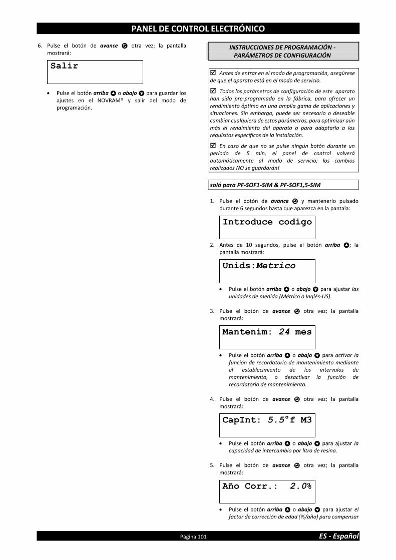
PANEL DE CONTROL ELECTRÓNICO
Página 101 ES - Español
6. Pulse el botón de avance otra vez; la pantalla mostrará:
• Pulse el botón arriba o abajo para guardar los ajustes en el NOVRAM® y salir del modo de programación.
INSTRUCCIONES DE PROGRAMACIÓN - PARÁMETROS DE CONFIGURACIÓN
Antes de entrar en el modo de programación, asegúrese de que el aparato está en el modo de servicio.
Todos los parámetros de configuración de este aparato han sido pre-programado en la fábrica, para ofrecer un rendimiento óptimo en una amplia gama de aplicaciones y situaciones. Sin embargo, puede ser necesario o deseable cambiar cualquiera de estos parámetros, para optimizar aún más el rendimiento del aparato o para adaptarlo a los requisitos específicos de la instalación.
En caso de que no se pulse ningún botón durante un período de 5 min, el panel de control volverá automáticamente al modo de servicio; los cambios realizados NO se guardarán!
soló para PF-SOF1-SIM & PF-SOF1,5-SIM
1. Pulse el botón de avance y mantenerlo pulsado
durante 6 segundos hasta que aparezca en la pantala: 2. Antes de 10 segundos, pulse el botón arriba ; la
pantalla mostrará:
• Pulse el botón arriba o abajo para ajustar las unidades de medida (Métrico o Inglés-US).
3. Pulse el botón de avance otra vez; la pantalla
mostrará:
• Pulse el botón arriba o abajo para activar la función de recordatorio de mantenimiento mediante el establecimiento de los intervalos de mantenimiento, o desactivar la función de recordatorio de mantenimiento.
4. Pulse el botón de avance otra vez; la pantalla
mostrará:
• Pulse el botón arriba o abajo para ajustar la capacidad de intercambio por litro de resina.
5. Pulse el botón de avance otra vez; la pantalla
mostrará:
• Pulse el botón arriba o abajo para ajustar el factor de corrección de edad (%/año) para compensar
Introduce codigo
Unids:Metrico
CapInt: 5.5°f M3
Mantenim: 24 mes
Año Corr.: 2.0%
Salir

PANEL DE CONTROL ELECTRÓNICO
ES - Español Página 102
la pérdida de capacidad de la resina debido al envejecimiento.
6. Pulse el botón de avance otra vez; la pantalla
mostrará:
• Pulse el botón arriba o abajo para ajustar el volumen de resina.
7. Pulse el botón de avance otra vez; la pantalla
mostrará:
• Pulse el botón arriba o abajo para ajustar el número de días entre regeneraciones.
8. Pulse el botón de avance otra vez; la pantalla
mostrará:
• Pulse el botón arriba o abajo para ajustar el tiempo de duración de cada ciclo de la regeneración.
• Pulse el botón de avance otra vez para advanzar al ciclo de regeneración siguiente.
Ciclo 1 Contralavado
Ciclo 2 Aspiracion de salmuera/lavado lento
Ciclo 3 Lavado ráp./reenvío de agua (PF-SOF1) Lavado rápido (PF-SOF1,5)
Ciclo 4 Reenvío de agua (PF-SOF1,5)
9. Pulse el botón de avance otra vez; la pantalla
mostrará:
• Pulse el botón arriba o abajo para ajustar el modo de regeneracón:
Retar./Inme.: cuando la capacidad restante es igual a la capacidad de reserva se desencadena una regenerción retardada a la hora de regeneración preprogramada; de todas maneras, si la capacidad restante llega a 0 antes de la hora de regeneración preprogramada, se desencadena inmediatamente la regeneración.
Inmediata: cuando la capacidad restane llega a 0 se desencadena una regeneración inmediata. Nota: regeneración manual Retardada no está disponible cuando se selecciona este modo de regeneración.
Retardada: cuando la capacidad restante iguala la capacidad de reserva, se desencadena una regeneración retardada a la hora de regeneración preprogramada.
10. Pulse el botón de avance otra vez; la pantalla mostrará (únicamente si la regeneración está a modo de ‘Retardada’ o ‘Retar/Inmd’):
• Pulse el botón arriba o abajo para ajustar la hora de regeneración.
11. Pulse el botón de avance otra vez; la pantalla mostrará
(únicamente si la regeneración está a modo de ‘Retardada’ o ‘Retar/Inmd’):
• Pulse el botón arriba o abajo para ajustar la capacidad de reserva:
Variable: la capacidad de reserva se calcula automáticamente a partir del consumo de agua diario registrado.
Fij: pulse el botón arriba o abajo para ajustar un valor fijo a la capacidad de reserva.
12. Pulse el botón de avance otra vez; la pantalla
mostrará:
• Pulse el botón arriba o abajo para ajustar función del contacto auxiliar 2:
Regen: el contacto auxiliar está activado durante toda la regeneración ( no incluye los ciclos de llenado y preparación de salmuera!)
Chlor.cell: el contacto auxiliar se activa al inicio del ciclo de lavado lento y aspiración de sal. Pulse nuevamente el botón avance y pulse arriba o abajo para fijar el tiempo de activación de la célula de cloración.
Mantenimiento: el contacto auxiliar se activa al aviso de mantenimiento.
Error : el contacto auxiliar se activa cuando se produce un error en el programador.
13. Pulse el botón de avance otra vez; la pantalla
mostrará:
• Pulse el botón arriba o abajo para guardar los ajustes en el NOVRAM® y salir del modo de programación.
Ciclo 1: XX min
Salir
Resina:XXX L
Ciclo: 7 días
Regen:Ret./Inme.
Rsrv Variable
Regen @ 2:00
AUX2: Regen

PANEL DE CONTROL ELECTRÓNICO
Página 103 ES - Español
soló para PF-SOF1-ALT & PF-SOF1,5-ALT
Los 2 sistemas Simlex que forman un sistema Dúplex deben programarse individualmente; NO es necesario que el programa sea el mismo para los dos sistemas!
1. Pulse el botón de avance y mantenerlo pulsado
durante 6 segundos hasta que aparezca en la pantala: 2. Antes de 10 segundos, pulse el botón arriba ; la
pantalla mostrará:
• Pulse el botón arriba o abajo para ajustar las unidades de medida (Métrico o Inglés-US).
3. Pulse el botón de avance otra vez; la pantalla
mostrará:
• Pulse el botón arriba o abajo para activar la función de recordatorio de mantenimiento mediante el establecimiento de los intervalos de mantenimiento, o desactivar la función de recordatorio de mantenimiento.
4. Pulse el botón de avance otra vez; la pantalla
mostrará:
• Pulse el botón arriba o abajo para ajustar la capacidad de intercambio por litro de resina.
5. Pulse el botón de avance otra vez; la pantalla
mostrará:
• Pulse el botón arriba o abajo para ajustar el factor de corrección de edad (%/año) para compensar la pérdida de capacidad de la resina debido al envejecimiento.
6. Pulse el botón de avance otra vez; la pantalla
mostrará:
• Pulse el botón arriba o abajo para ajustar el volumen de resina.
7. Pulse el botón de avance otra vez; la pantalla mostrará:
• Pulse el botón arriba o abajo para ajustar el número de días entre regeneraciones.
8. Pulse el botón de avance otra vez; la pantalla
mostrará:
• Pulse el botón arriba o abajo para ajustar el tiempo de duración de cada ciclo de la regeneración.
• Pulse el botón de avance otra vez para advanzar al ciclo de regeneración siguiente.
Ciclo 1 Contralavado
Ciclo 2 Aspiracion de salmuera/lavado lento
Ciclo 3 Lavado ráp./reenvío de agua (PF-SOF1) Lavado rápido (PF-SOF1,5)
Ciclo 4 Reenvío de agua (PF-SOF1,5)
9. Pulse el botón de avance otra vez; la pantalla
mostrará:
• Pulse el botón arriba o abajo para ajustar función del contacto auxiliar 2:
Regen: el contacto auxiliar está activado durante toda la regeneración ( no incluye los ciclos de llenado y preparación de salmuera!)
Chlor.cell: el contacto auxiliar se activa al inicio del ciclo de lavado lento y aspiración de sal. Pulse nuevamente el botón avance y pulse arriba o abajo para fijar el tiempo de activación de la célula de cloración.
Mantenimiento: el contacto auxiliar se activa al aviso de mantenimiento.
Error : el contacto auxiliar se activa cuando se produce un error en el programador.
10. Pulse el botón de avance otra vez; la pantalla
mostrará:
• Pulse el botón arriba o abajo para guardar los ajustes en el NOVRAM® y salir del modo de programación.
11. Repita los pasos de 1-10 para los dos sistemas Simplex.
Salir
Ciclo 1: XX min
Introduce codigo
Unids:Metrico
Resina:XXX L
CapInt: 5.5°f M3
Ciclo: 7 días
Mantenim: 24 mes
Año Corr.: 2.0%
AUX2: Regen

PANEL DE CONTROL ELECTRÓNICO
ES - Español Página 104
soló para PF-SOF1-PRL & PF-SOF1,5-PRL
Los 2 sistemas Simlex que forman un sistema Dúplex deben programarse individualmente; NO es necesario que el programa sea el mismo para los dos sistemas!
1. Pulse el botón de avance y mantenerlo pulsado
durante 6 segundos hasta que aparezca en la pantala: 2. Antes de 10 segundos, pulse el botón arriba ; la
pantalla mostrará:
• Pulse el botón arriba o abajo para ajustar las unidades de medida (Métrico o Inglés-US).
3. Pulse el botón de avance otra vez; la pantalla
mostrará:
• Pulse el botón arriba o abajo para activar la función de recordatorio de mantenimiento mediante el establecimiento de los intervalos de mantenimiento, o desactivar la función de recordatorio de mantenimiento.
4. Pulse el botón de avance otra vez; la pantalla
mostrará:
• Pulse el botón arriba o abajo para ajustar la capacidad de intercambio por litro de resina.
5. Pulse el botón de avance otra vez; la pantalla
mostrará:
• Pulse el botón arriba o abajo para ajustar el factor de corrección de edad (%/año) para compensar la pérdida de capacidad de la resina debido al envejecimiento.
6. Pulse el botón de avance otra vez; la pantalla
mostrará:
• Pulse el botón arriba o abajo para ajustar el volumen de resina.
7. Pulse el botón de avance otra vez; la pantalla mostrará:
• Pulse el botón arriba o abajo para ajustar el número de días entre regeneraciones.
8. Pulse el botón de avance otra vez; la pantalla
mostrará:
• Pulse el botón arriba o abajo para ajustar el tiempo de duración de cada ciclo de la regeneración.
• Pulse el botón de avance otra vez para advanzar al ciclo de regeneración siguiente.
Ciclo 1 Contralavado
Ciclo 2 Aspiracion de salmuera/lavado lento
Ciclo 3 Lavado ráp./reenvío de agua (PF-SOF1) Lavado rápido (PF-SOF1,5)
Ciclo 4 Reenvío de agua (PF-SOF1,5)
9. Pulse el botón de avance otra vez; la pantalla
mostrará:
• Pulse el botón arriba o abajo para ajustar el modo de regeneracón:
• Inmediata: cuando la capacidad restane llega a 0 se desencadena una regeneración inmediata. Nota: regeneración manual Retardada no está disponible cuando se selecciona este modo de regeneración.
Retar./Inme.: cuando la capacidad restante es igual a la capacidad de reserva se desencadena una regenerción retardada a la hora de regeneración preprogramada; de todas maneras, si la capacidad restante llega a 0 antes de la hora de regeneración preprogramada, se desencadena inmediatamente la regeneración.
Retardada: cuando la capacidad restante iguala la capacidad de reserva, se desencadena una regeneración retardada a la hora de regeneración preprogramada.
10. Pulse el botón de avance otra vez; la pantalla mostrará
(únicamente si la regeneración está a modo de ‘Retardada’ o ‘Retar/Inmd’):
• Pulse el botón arriba o abajo para ajustar la hora de regeneración.
Regen:Inmediata
Regen @ 2:00
Ciclo 1: XX min
Introduce codigo
Unids:Metrico
Resina:XXX L
CapInt: 5.5°f M3
Ciclo: 7 días
Mantenim: 24 mes
Año Corr.: 2.0%

PANEL DE CONTROL ELECTRÓNICO
Página 105 ES - Español
11. Pulse el botón de avance otra vez; la pantalla mostrará (únicamente si la regeneración está a modo de ‘Retardada’ o ‘Retar/Inmd’):
• Pulse el botón arriba o abajo para ajustar la capacidad de reserva:
Variable: la capacidad de reserva se calcula automáticamente a partir del consumo de agua diario registrado.
Fij: pulse el botón arriba o abajo para ajustar un valor fijo a la capacidad de reserva.
12. Pulse el botón de avance otra vez; la pantalla
mostrará:
• Pulse el botón arriba o abajo para ajustar función del contacto auxiliar 2:
Regen: el contacto auxiliar está activado durante toda la regeneración ( no incluye los ciclos de llenado y preparación de salmuera!)
Chlor.cell: el contacto auxiliar se activa al inicio del ciclo de lavado lento y aspiración de sal. Pulse nuevamente el botón avance y pulse arriba o abajo para fijar el tiempo de activación de la célula de cloración.
Mantenimiento: el contacto auxiliar se activa al aviso de mantenimiento.
Error : el contacto auxiliar se activa cuando se produce un error en el programador.
13. Pulse el botón de avance otra vez; la pantalla
mostrará:
• Pulse el botón arriba o abajo para guardar los ajustes en el NOVRAM® y salir del modo de programación.
14. Repita los pasos de 1-13 para los dos sistemas Simplex.
Salir
Rsrv Variable
AUX2: Regen

MANTENIMIENTO
ES - Español Página 106
RECOMENDACIÓN
A pesar de la fiabilidad del aparato, recomendamos la realización de un mantenimiento periódico por un técnico competente y debidamente formado. Asimismo será necesario determinar el intervalo del mantenimiento apropiado en función de la aplicación específica y de las condiciones de uso locales. Las ventajas de un mantenimiento regular son las siguientes:
• control periódico de las condiciones de suministro locales (calidad del agua, presión, etc..)
• control y regulación periódica de los parámetros del aparato, con el fin de garantizar un óptimo funcionamiento.
• minimizar el riesgo de una avería no atendida. Contacte con su vendedor o su instalador para más información o visite nuestra página web.
CONTROLES REGULARES
El usuario debe realizar periódicamente una comprobación básica para verificar si el aparato está funcionando correctamente, sobre la base de los siguientes puntos: 1. Comprobar configuración del panel de contr. electrónico. 2. Medir dureza del agua antes/después del aparato. 3. Comprobar manguera de desagüe de válvula de control;
no debería haber ningún flujo de agua (a menos que el aparato esté en regeneración).
4. Comprobar manguera del rebosadero del depósito de salmuera; no debería haber ningún flujo de agua.
5. Comprobar el aparato y la zona que lo rodea; asegurarse que no hay fugas de agua
PONER EN BYPASS EL APARATO
Ocasionalmente, puede ser necesario poner el aparato en derivación hidráulica, es decir, para aislarlo de la red de distribución de agua; ej.:
• en el caso de un problema técnico urgente;
• cuando no es necesario suministrar agua tratada a servicio.
CON BYPASS DE FÁBRICA (opcional) (soló para PF-SOF1)
Imagen 15.a
POSICIÓN DE SERVICIO = válvula de entrada al aparato está ABIERTA ❖ = válvula de salida al aparato está ABIERTA
Imagen 15.b
POSICIÓN DE DERIVACIÓN = válvula de entrada al aparato está CERRADA ❖ = válvula de salida al aparato está CERRADA
Imagen 15.c
POSICIÓN DE MANTENIMIENTO = válvula de entrada al aparato está ABIERTA ❖ = válvula de salida al aparato está CERRADA
SAL PARA DESCALCIFICADOR DE AGUA
El aparato necesita 'salmuera' para sus regeneraciones periódicas. Esta solución de salmuera está hecha de agua, que es automáticamente dosificada en el depósito de salmuera por la válvula de control, y la sal para descalcificador de agua. El usuario debe asegurarse de que el depósito de salmuera se mantiene siempre lleno de sal para descalcificador de agua. Por lo tanto se debe comprobar periódicamente el nivel de sal en el interior del depósito de salmuera y rellenar si es necesario. Simplemente levantar la tapa del depósito de salmuera para comprobar el nivel de sal en el interior del depósito de salmuera. El nivel de sal dentro del depósito de salmuera se debe mantener entre 1/3 y 2/3. Un nivel bajo puede causar una insuficiente saturación de salmuera, lo que resulta en una pérdida de capacidad de intercambio. Un mayor nivel puede causar una 'caverna de sal' (o una dura costra de sal en el depósito de salmuera). Cuando usted sospechea que aparecen estas costras:
• cuidadosamente golpear contra l’exterior del depósito de salmuera, para romper las costras de sal;
• con una palo (o con una herramienta roma) presione cuidadosamente la sal para separarla;
• viertar agua tibia sobre la sal para que se disuelva.
LIMPIEZA DE RESINA
Otros contaminantes (ej. hierro) presentes en el agua de aporte, puede dañar o estropear el lecho de resina, lo que provoca una pérdida de rendimiento del equipo. Se puede utilizar periódicamente un limpiador de resina para limpiar a fondo el lecho de resina.
DESINFECCIÓN DEL APARATO
Este aparato está fabricado con materiales de primera calidad y montados en unas condiciones seguras para garantizar que esté limpio y desinfectado. Si la instalación y el mantenimien-to son correctos el aparato no va a infectar ni contaminar el suministro de agua. Sin embargo, como en cualquier dispositivo sondeado en su sistema de distribución de agua, la proliferación de bacterias es posible, especialmente en el caso de 'agua estancada'. Por lo tanto este aparato está equipado con una función de 'anulación de día', que automáticamente va a enjuagar el lecho de resina periódi-camente, incluso en caso de baja o ausenica del uso de agua. Si la fuente de alimentación del aparato se desconecta por un período de tiempo más largo, se recomienda, cuando la fuente de alimentación se restablece, iniciar manualmente una regeneración completa.
VÁLVULAS DE SERVICIO NORMALEMENTE CERRADA
(soló para PF-SOF1-ALT & PF-SOF1,5-ALT)
Imagen 16
= accionamiento automático = normalemente cerrada ❖ = accionamiento manual = constantemente abierto La Válvula de Servicio Normalmente Cerrada en la salida de cada sistema Simplex únicamente se abrirá cuando reciba tensión. Para abrir manualmente la Válvula de Servicio NC (por ejemplo por un fallo re corriente) es sufifiente con girar la bobina blanca en sentido anti-horario.
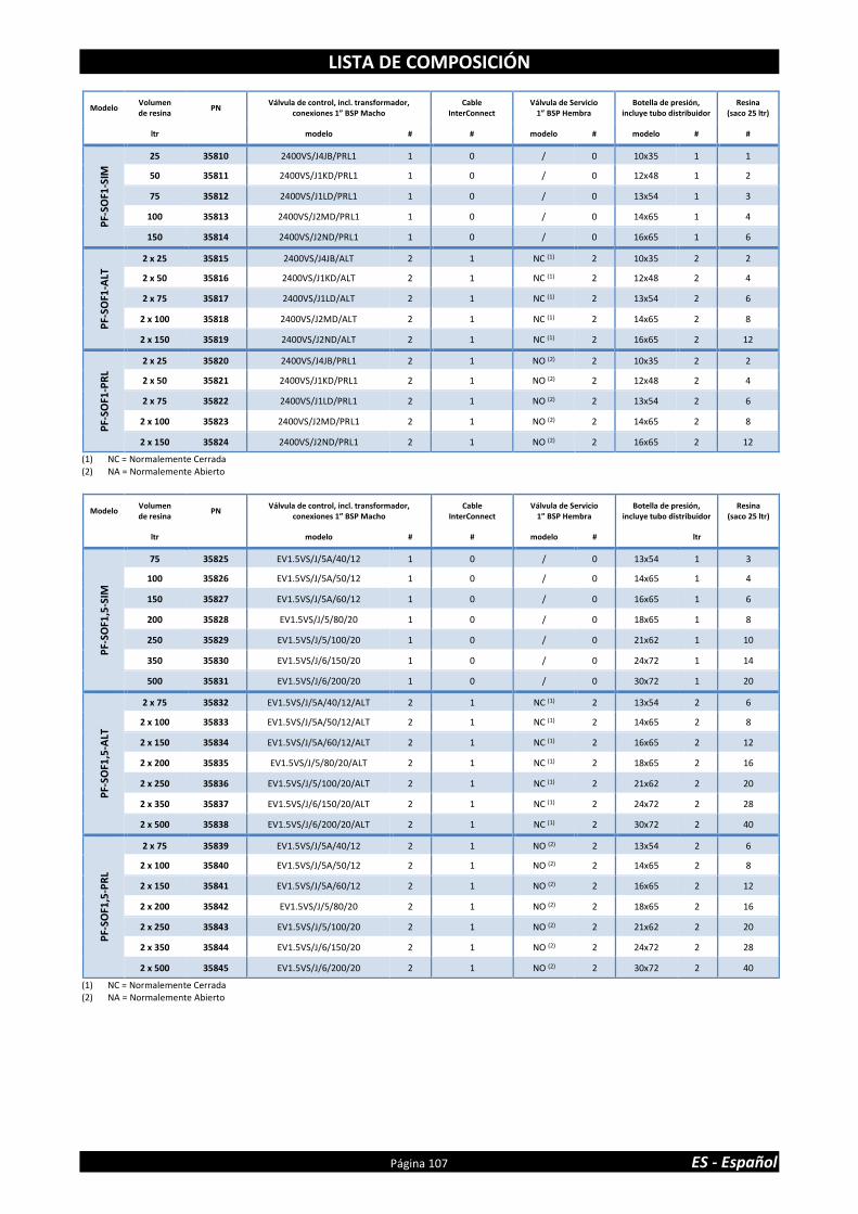
LISTA DE COMPOSICIÓN
Página 107 ES - Español
Modelo Volumen de resina
PN Válvula de control, incl. transformador,
conexiones 1” BSP Macho Cable
InterConnect Válvula de Servicio
1” BSP Hembra Botella de presión,
incluye tubo distribuidor Resina
(saco 25 ltr)
ltr modelo # # modelo # modelo # #
PF-
SOF1
-SIM
25 35810 2400VS/J4JB/PRL1 1 0 / 0 10x35 1 1
50 35811 2400VS/J1KD/PRL1 1 0 / 0 12x48 1 2
75 35812 2400VS/J1LD/PRL1 1 0 / 0 13x54 1 3
100 35813 2400VS/J2MD/PRL1 1 0 / 0 14x65 1 4
150 35814 2400VS/J2ND/PRL1 1 0 / 0 16x65 1 6
PF-
SOF1
-ALT
2 x 25 35815 2400VS/J4JB/ALT 2 1 NC (1) 2 10x35 2 2
2 x 50 35816 2400VS/J1KD/ALT 2 1 NC (1) 2 12x48 2 4
2 x 75 35817 2400VS/J1LD/ALT 2 1 NC (1) 2 13x54 2 6
2 x 100 35818 2400VS/J2MD/ALT 2 1 NC (1) 2 14x65 2 8
2 x 150 35819 2400VS/J2ND/ALT 2 1 NC (1) 2 16x65 2 12
PF-
SOF1
-PR
L
2 x 25 35820 2400VS/J4JB/PRL1 2 1 NO (2) 2 10x35 2 2
2 x 50 35821 2400VS/J1KD/PRL1 2 1 NO (2) 2 12x48 2 4
2 x 75 35822 2400VS/J1LD/PRL1 2 1 NO (2) 2 13x54 2 6
2 x 100 35823 2400VS/J2MD/PRL1 2 1 NO (2) 2 14x65 2 8
2 x 150 35824 2400VS/J2ND/PRL1 2 1 NO (2) 2 16x65 2 12
(1) NC = Normalemente Cerrada (2) NA = Normalemente Abierto
Modelo Volumen de resina
PN Válvula de control, incl. transformador,
conexiones 1” BSP Macho Cable
InterConnect Válvula de Servicio
1” BSP Hembra Botella de presión,
incluye tubo distribuidor Resina
(saco 25 ltr)
ltr modelo # # modelo # ltr
PF-
SOF1
,5-S
IM
75 35825 EV1.5VS/J/5A/40/12 1 0 / 0 13x54 1 3
100 35826 EV1.5VS/J/5A/50/12 1 0 / 0 14x65 1 4
150 35827 EV1.5VS/J/5A/60/12 1 0 / 0 16x65 1 6
200 35828 EV1.5VS/J/5/80/20 1 0 / 0 18x65 1 8
250 35829 EV1.5VS/J/5/100/20 1 0 / 0 21x62 1 10
350 35830 EV1.5VS/J/6/150/20 1 0 / 0 24x72 1 14
500 35831 EV1.5VS/J/6/200/20 1 0 / 0 30x72 1 20
PF-
SOF1
,5-A
LT
2 x 75 35832 EV1.5VS/J/5A/40/12/ALT 2 1 NC (1) 2 13x54 2 6
2 x 100 35833 EV1.5VS/J/5A/50/12/ALT 2 1 NC (1) 2 14x65 2 8
2 x 150 35834 EV1.5VS/J/5A/60/12/ALT 2 1 NC (1) 2 16x65 2 12
2 x 200 35835 EV1.5VS/J/5/80/20/ALT 2 1 NC (1) 2 18x65 2 16
2 x 250 35836 EV1.5VS/J/5/100/20/ALT 2 1 NC (1) 2 21x62 2 20
2 x 350 35837 EV1.5VS/J/6/150/20/ALT 2 1 NC (1) 2 24x72 2 28
2 x 500 35838 EV1.5VS/J/6/200/20/ALT 2 1 NC (1) 2 30x72 2 40
PF-
SOF1
,5-P
RL
2 x 75 35839 EV1.5VS/J/5A/40/12 2 1 NO (2) 2 13x54 2 6
2 x 100 35840 EV1.5VS/J/5A/50/12 2 1 NO (2) 2 14x65 2 8
2 x 150 35841 EV1.5VS/J/5A/60/12 2 1 NO (2) 2 16x65 2 12
2 x 200 35842 EV1.5VS/J/5/80/20 2 1 NO (2) 2 18x65 2 16
2 x 250 35843 EV1.5VS/J/5/100/20 2 1 NO (2) 2 21x62 2 20
2 x 350 35844 EV1.5VS/J/6/150/20 2 1 NO (2) 2 24x72 2 28
2 x 500 35845 EV1.5VS/J/6/200/20 2 1 NO (2) 2 30x72 2 40
(1) NC = Normalemente Cerrada (2) NA = Normalemente Abierto

DATOS TÉCNICOS - PF-SOF1
ES - Español Página 108
Especificaciones técnicas:
(1) Suministrado con transformador 24 VDC
Rendimiento @ presión operacional de 3 bar(2): (2) Valores indicatives, Rendimiento dependiendo de las condiciones de servicio y calidad del agua.
Modelo PF-SOF1-SIM / PF-SOF1-ALT / PF-SOF1-PRL
Resina (ltr) 25 50 75 100 150
Presión de trabajo mín/máx (bar) 1,4/8,3
Temperatura de trabajo mín/máx (°C) 2/48
Conexión eléctrica (V/Hz) 230/50(1)
Cons. de energ. máx. Simplex/Dúplex (VA) 8
Conexión hidráulica entrada/salida 1” BSP Macho
Conexión hidráulica desagüe 19 mm espiga
Conexión hidráulica depósito de salmuera ⅜” connexion rápida
Botella de presión 10x35 12x48 13x54 14x65 16x65
Modelo PF-SOF1-SIM
Resina (ltr) 25 50 75 100 150
Capacidad de intercambio nom. (m³x°f) 138 275 413 550 825
Capacidad de intercambio nom. (m³x°d) 78 155 233 310 465
Caudal de servicio @∆p 1 bar (m³/hr) 3,4 3,4 3,5 3,5 3,6
Consumo de sal por regeneración (kg) 3,8 7,5 11,3 15,0 22,5
Consumo de agua por regeneración (ltr) 165 285 400 540 780
Caudal de desagüe max. (ltr/min) 9,8 13,2 15,1 18,9 22,7
Modelo PF-SOF1-ALT
Resina (ltr) 2x25 2x50 2x75 2x100 2x150
Capacidad de intercambio nom. (m³x°f) 275 550 825 1.100 1.650
Capacidad de intercambio nom. (m³x°d) 155 310 465 620 930
Caudal de servicio @∆p 1 bar (m³/hr) 3,4 3,4 3,5 3,5 3,6
Consumo de sal por regeneración (kg) 7,5 15,0 22,5 30,0 45,0
Consumo de agua por regeneración (ltr) 330 570 800 1.080 1.560
Caudal de desagüe max. (ltr/min) 9,8 13,2 15,1 18,9 22,7
Modelo PF-SOF1-PRL
Resina (ltr) 2x25 2x50 2x75 2x100 2x150
Capacidad de intercambio nom. (m³x°f) 275 550 825 1.100 1.650
Capacidad de intercambio nom. (m³x°d) 155 310 465 620 930
Caudal de servicio @∆p 1 bar (m³/hr) 6,7 6,8 7,0 7,0 7,2
Consumo de sal por regeneración (kg) 7,5 15,0 22,5 30,0 45,0
Consumo de agua por regeneración (ltr) 330 570 800 1.080 1.560
Caudal de desagüe max. (ltr/min) 9,8 13,2 15,1 18,9 22,7

DATOS TÉCNICOS - PF-SOF1
Página 109 ES - Español
Dimensiones:
Modelo PF-SOF1-SIM
Resina (ltr) 25 50 75 100 150
Anchura (mm) (W) 264 311 338 365 415
Profundidad (mm) (D) 282 311 338 365 415
Profund., incl. bypass de fábrica (mm) (D) 371 376 389 403 428
Altura (mm) (H) 1.059 ±10 1.394 ±10 1.560 ±10 1.836 ±10 1.833 ±10
Modelo PF-SOF1-ALT / PF-SOF1-PRL
Resina (ltr) 2x25 2x50 2x75 2x100 2x150
Anchura (mm) (W) (1) 613 707 761 815 915
Profundidad (mm) (D) 405 410 436 463 513
Altura (mm) (H) 1.059 ±10 1.394 ±10 1.560 ±10 1.836 ±10 1.833 ±10 (1) Sobre la base de 85 mm de separación

DATOS TÉCNICOS - PF-SOF1,5
ES - Español Página 110
Especificaciones técnicas:
(1) Suministrado con transformador 24 VAC
Rendimiento @ presión operacional de 3 bar(2): (2) Valores indicatives, Rendimiento dependiendo de las condiciones de servicio y calidad del agua.
Modelo PF-SOF1,5-SIM / PF-SOF1,5-ALT / PF-SOF1,5-PRL
Resina (ltr) 75 100 150 200 250 350 500
Presión operacional mín/máx (bar) 1,4/8,0
Temperatura operacional mín/máx (°C) 2/48
Conexión eléctrica (V/Hz) 230/50(1)
Cons. de energ. máx. Simplex/Dúplex (VA) 80/2x89
Conexión hidráulica entrada/salida 1,5” BSP Macho/Hembra
Conexión hidráulica desagüe 1” BSP Macho
Conexión hidráulica depósito de salmuera ½” connexion rápida
Botella de presión 13x54 14x65 16x65 18x65 21x62 24x72 30x72
Modelo PF-SOF1,5-SIM
Resina (ltr) 75 100 150 200 250 350 500
Capacidad de intercambio nom. (m³x°f) 413 550 825 1.100 1.375 1.925 2.750
Capacidad de intercambio nom. (m³x°d) 233 310 465 620 775 1.085 1.550
Caudal de servicio @∆p 1 bar (m³/hr) 7,8 7,8 7,8 7,9 7,9 8,0 8,0
Consumo de sal por regeneración (kg) 11,3 15,0 22,5 30,0 37,5 52,5 75,0
Consumo de agua por regeneración (ltr) 469 578 838 1.148 1.435 2.140 3.030
Caudal de desagüe max. (ltr/min) 15,2 19,0 22,7 30,3 37,9 56,8 75,7
Modelo PF-SOF1,5-ALT
Resina (ltr) 2x75 2x100 2x150 2x200 2x250 2x350 2x500
Capacidad de intercambio nom. (m³x°f) 825 1.100 1.650 2.200 2.750 3.850 5.500
Capacidad de intercambio nom. (m³x°d) 465 620 930 1.240 1.550 2.170 3.100
Caudal de servicio @∆p 1 bar (m³/hr) 7,8 7,8 7,8 7,9 7,9 8,0 8,0
Consumo de sal por regeneración (kg) 22,5 30,0 45,0 60,0 75,0 105,0 150,0
Consumo de agua por regeneración (ltr) 938 1.156 1.676 2.296 2.870 4.280 6.060
Caudal de desagüe max. (ltr/min) 15,2 19,0 22,7 30,3 37,9 56,8 75,7
Modelo PF-SOF1,5-PRL
Resina (ltr) 2x75 2x100 2x150 2x200 2x250 2x350 2x500
Capacidad de intercambio nom. (m³x°f) 825 1.100 1.650 2.200 2.750 3.850 5.500
Capacidad de intercambio nom. (m³x°d) 465 620 930 1.240 1.550 2.170 3.100
Caudal de servicio @∆p 1 bar (m³/hr) 15,6 15,6 15,6 15,8 15,8 16,0 16,0
Consumo de sal por regeneración (kg) 22,5 30,0 45,0 60,0 75,0 105,0 150,0
Consumo de agua por regeneración (ltr) 938 1.156 1.676 2.296 2.870 4.280 6.060
Caudal de desagüe max. (ltr/min) 15,2 19,0 22,7 30,3 37,9 56,8 75,7

DATOS TÉCNICOS - PF-SOF1,5
Página 111 ES - Español
Dimensiones:
Modelo PF-SOF1,5-SIM
Resina (ltr) 75 100 150 200 250 350 500
Anchura (mm) (W) 390 403 428 491 555 635 786
Profundidad (mm) (D) 575 575 575 595 627 667 786
Altura (mm) (H) 1.623 1.904 1.901 1.952 1.951 2.148 2.066
Model
PF-SOF1,5-ALT / PF-SOF1,5-PRL
Resin (ltr) 2x75 2x100 2x150 2x200 2x250 2x350 2x500
Anchura (mm) (W) (1) 930 956 1.006 1.132 1.260 1.420 1.722
Profundidad (mm) (D) 690 690 690 706 738 778 850
Altura (mm) (H) 1.623 1.904 1.901 1.952 1.951 2.148 2.066 (1) Sobre la base de 150 mm de separación

DATOS TÉCNICOS - PF-BTA
ES - Español Página 112
Especificaciones técnicas:
Dimensiones:
Modelo PF-BTA
Volumen (ltr) 125 275 500 750
Diámetro (mm) (D) 540 685 875 1.030
Altura (mm) (H) 850 975 1.110 1.110
Altura rebosadero (mm) (H1) 660 825 945 945
Cap. max. de almacenamiento de sal (kg) 100 200 475 700
Modelo PF-BTA
Volumen (ltr) 125 275 500 750
Conexión hidráulica válvula de salmuera intercambiable: ⅜” Quick-Fit & ½” connexion rápida
Conexión hidráulica rebosadero 19 mm espiga

SPIS TREŚCI I DANE DOTYCZĄCE INSTALACJI
Strona 113 PL - Polska
Spis treści i Dane dotyczące instalacji ................................................................................. Strona 113
Ostrzeżenia i Instrukcje bezpieczeństwa ............................................................................ Strona 114
Warunki pracy i Wymagania ............................................................................................... Strona 115
Montaż ................................................................................................................................ Strona 116
Instalacja ............................................................................................................................. Strona 118
Rozruch ............................................................................................................................... Strona 120
Elektroniczny panel sterowania .......................................................................................... Strona 121
Konserwacja ........................................................................................................................ Strona 128
Przegląd składników ............................................................................................................ Strona 129
Dane techniczne - PF-SOF1 ................................................................................................. Strona 130
Dane techniczne - PF-SOF1,5 .............................................................................................. Strona 132
Dane techniczne - PF-BTA ................................................................................................... Strona 134
Prosimy o uzupełenienie poniższych danych, do przyszłego użytku
DANE DOTYCZĄCE INSTALACJI Numer seryjny: _______________________________________________
Model: ________________________________________________________ Twardość wody na wlocie: __________________________________ Twardość wody na wylocie: _________________________________ Ciśnienie wody na wlocie: ___________________________________
Data instalacji: _______________________________________________
Nazwa firmy: _________________________________________________
Nazwisko instalatora: ________________________________________ Numer telefonu: _____________________________________________

OSTRZEŻENIA i INSTRUKCJE BEZPIECZEŃSTWA
PL - Polska Strona 114
• Przed rozpoczęciem instalacji urządzenia, zalecamy przeczytanie i dokładne zastosowanie instrukcji zawartych w niniejszym dokumencie. Zawiera on ważne informacje dotyczące bezpieczeństwa, instalacji, eksploatacji i konserwacji produktu. System, który trafia do Państwa rąk może różnić się od tego przedstawionego na zdjęcia/ilustracjach/opisy zawartych w niniejszej Instrukcji.
• Niestosowanie się do niniejszej instrukcji może stać się przyczyną obrażeń
ciała, oraz uszkodzeń sprzętu lub mienia. Tylko prawidłowa instalacja, rozruch i eksploatacja zapewnia wieloletnie bezproblemowe działanie systemu uzdatniania wody.
• Urządzenie zaprojektowany jest do zmiękczania wody tzn. do usuwania
minerałów powodujących dużą twardość wody, jednakże urządzenie to niekoniecznie nadaje się do usuwania innych substancji zanieczyszczające wodę. Zmiękczacz nie będzie oczyszczał wody, ani nie będzie jej uzdatniał w innym zakresie niż zmniejszenie twardości.
• Tylko kompetentna osoba, znająca obowiązujące lokalne przepisy, może
przeprowadzać instalację urządzenia. Wszystkie złącza elektryczne i wodociągowe muszą być wykonane zgodnie z lokalnymi przepisami.
• Przed ustawieniem urządzenia, należy sprawdzić czy nie ma on żadnych
widocznych zewnętrznych uszkodzeń – nie instalować uszkodzonego urządzenia.
• Stosować wózek ręczny do transportu urządzenia. Aby zapobiec wypadkom
oraz obrażeniom, nie przenosić urządzenia na ramieniu. Nie kłaść urządzenia na boku.
• Przechowywać niniejszą Instrukcję w bezpiecznym miejscu i upewnić się, że
nowi użytkownicy zapoznali się z jej treścią. • System uzdatniania wody zaprojektowano i wyprodukowano zgodnie z
najnowszymi wymogami i przepisami bezpieczeństwa. Niewłaściwe naprawy mogą być przyczyną nieprzewidzianych zagrożeń dla użytkownika, za które producent nie ponosi odpowiedzialności. W związku z tym wszelkie naprawy powinny być przeprowadzane przez kompetentnego pracownika, znającego ten produkt i specjalnie przeszkolonego.
• Urządzenie powinno być utylizowane zgodnie z wymogami dotyczącymi
odpadów elektrycznych i elektronicznych. W tym celu należy działać zgodnie z obowiązującymi przepisami krajowymi i lokalnymi.

WARUNKI PRACY I WYMAGANIA
Strona 115 PL - Polska
• CIŚNIENIE ROBOCZE MIN-MAKS: 1,4-8,0 bar / 20-116 psi to urządzenie jest skonfigurowane tak, aby pracować optymalnie przy
ciśnieniu pracy 3 bar (45 psi) ±½ bar (7 psi); niższe lub wyższe ciśnienie pracy może wpłynąć negatywnie na jego wydajność!
regularnie sprawdzać ciśnienie wody; może wahać się poważnie w zależności od pory dnia, dnia tygodnia, a nawet pory roku.
należy uwzględnić fakt, że ciśnienie wody w nocy może być znacznie większe niż w dzień.
jeśli jest to konieczne, zainstalować reduktor ciśnienia przed urządzeniem.
zainstalowanie pompy wzmacniającej ciśnienie, jeżeli jest prawdopodobne, że ciśnienie wody może spaść poniżej minimum.
• TEMPERATURA ROBOCZA MIN-MAKS: 2-48 °C / 35-120 °F nie instalować urządzenia w środowisku, w którym narażony będzie
na wysokie temperatury (np. niewentylowane kotłownie) lub na temperatury powodujące zamarzanie.
urządzenie nie może być narażone na kontakt z czynnikami atmosferycznymi takimi jak bezpośrednie promienie słoneczne lub opady.
nie instalować urządzenia zbyt blisko podgrzewacza wody, zachować odległość przynajmniej 3 metrów (10 ft) orurowania pomiędzy wylotem wody z systemu a wlotem wody do podgrzewacza wody; podgrzewacze wody mogą czasami przekazywać ciepło z powrotem wzdłuż rury wody zimnej do zaworu sterującego; zawsze instalować zawór odcinający na wylocie z urządzenia.
• ZŁĄCZE ELEKTRYCZNE: niniejsze urządzenie pracuje z zasilaniem 24 V; należy zawsze
stosować transformator dostarczony z urządzeniem.
w przypadku uszkodzenia przewodu zasilającego transformator, odłącz go natychmiast od źródła prądu oraz wymień transformator na nowy.
upewnić się, że transformator podłączony jest do gniazda zasilającego, które zainstalowano w suchym otoczeniu i z właściwymi parametrami znamionowymi oraz z zabezpieczeniem nadprądowym.

MONTAŻ
PL - Polska Strona 116
SPRAWDZENIE ZAWARTOŚCI OPAKOWANIA
Części, które trafiają do Państwa rąk mogą różnić się od tych przedstawionych na fotografiach/ilustracjach zawartych w niniejszej instrukcji!
Aby ułatwić transport i instalację, zmiękczająca żywica NIE jest załadowana do zbiornika ciśnieniowego - dostarczana jest w oddzielnych workach po 25 ltr każdy; należy ją umieścić w zbiorniku ciśnieniowym na miejscu instalacji, po ustawieniu zbiornika ciśnieniowego.
Sprawdzić skład sytemu, używając do tego Przeglądu Składników, umieszczonego na końcu niniejszej instrukcji. Określić i odpowiednio rozmieścić różne składniki, aby ułatwić montaż.
SIMPLEX (PF-SOF1-SIM & PF-SOF1,5-SIM)
System Simplex zawiera 1 pojedyńczy moduł zmiękczający (zbiornik ciśnieniowy, żywica, głowica sterująca i akcesoria).
W trakcie normalnej pracy, system Simplex dostarcza zmiękczoną wodę. W momencie rozpoczęcia regeneracji, przechodzi automatycznie w tryb obejścia wody surowej, gwarantując nieprzerwaną dostawę (nieuzdatnionej) wody. Ponieważ system Simplex wyposażony jest, w standardzie, w port równoległej komunikacji, możliwe jest rozbudowanie systemu Simplex do systemu Duplex Parallel, przez dołożenie drugiego systemu Simplex.
DUPLEX ALTERNATING (PF-SOF1-ALT & PF-SOF1,5-ALT)
System Duplex ALTERNATING składa się z dwóch systemów Simplex Eco, które: - są połączone hydraulicznie w parallel; - są wyposażone w port komunikacyjny Alternating
InterConnect; - są połączone elektronicznie przewodem połączeniowym; - mają normalnie zamknięty zawór elektromagnetyczny
membranowy (zwany zaworem serwisowym) na wyjściu z każdego systemu Simplex; zawór ten jest sterowany zegarem elektronicznym każdego z systemów Simplex i jest aktywowany podczas cyklu serwis w celu otwarcia wyjścia wody odpowiedniego systemu Simplex.
- współdzielą 1 zbiornik solanki, który zawiera 2 zawory pływakowe.
Podczas normalnej pracy tylko jeden z dwóch systemów Simplex jest w trybie „serwis”, podczas gdy drugi system się regeneruje, lub jest w trybie oczekiwania! W momencie, gdy pierwszy system Simplex inicjuje regenerację, drugi system przechodzi w tryb serwis, gwarantując nieprzerwaną dostawę miękkiej wody. W przypadku zaniku prądu, oba zawory serwisowe zostają zamknięte, co oznacza, że wyjścia wody obu systemów Simplex zostają zamknięte, odcinając tym samym dopływ (potencjalnie twardej) wody.
DUPLEX PARALLEL (PF-SOF1-PRL & PF-SOF1,5-PRL)
System Duplex PARALLEL składa się z 2 systemów Simplex, które: - są połączone hydraulicznie w system parallel; - są wyposażone w port komunikacyjny Parallel
InterConnect; - są połączone elektronicznie przewodem połączeniowym; - mają normalnie otwarty zawór elektromagnetyczny
membranowy (zwany zaworem serwisowym) na wyjściu z każdego systemu Simplex; zawór ten jest sterowany przez zegar sterujący systemu i jest załączony podczas całego cyklu regeneracji, aby wyłączyć obejście wody surowej w głowicy.
- współdzielą 1 zbiornik solanki, który zawiera 2 zawory pływakowe.
Podczas normalnej pracy, oba systemy Simplex są w pozycji serwis, podwajając przepływ wody! Jeden z systemów Simplex inicjuje regenerację, wysyłając jednocześnie komunikat do pozostałych systemów Simplex poprzez kabel połączeniowy, aby upewnić się, że pozostałe systemy pozostają w pozycji serwis, gwarantując nieprzerwaną dostawę miękkiej wody. W przypadku zaniku prądu wszystkie zawory serwisowe zostają wyłączone, co oznacza, że wyjścia wody z wszystkich systemów Simplex zostają otwarte, gwarantując nieprzerwaną dostawę wody. Dla prawidłowego montażu, powtórz poszczególne etapy montażu, aż wszystkie systemy Simplex są zamontowane i prawidłowo ustawione. Dla dużych instalacji o dużym zapotrzebowaniu na uzdatnioną wodę, można zainstalować dwa lub więcej równoległych, hydraulicznych systemów podwójnych aby podwoić/potroić przepływ i wydajność zmiękczania.
ŁADOWANIE ŻYWICY
1. Przesunąć zbiornik ciśnieniowy na właściwą pozycję
instalacyjną; umieścić na płaskiej i równej powierzchni. Upewnić się, że pozostawiono wystarczającą przestrzeń do łatwego montażu.
2. Umieścić rurę dystrybucyjną pionowo i centralnie w zbiorniku ciśnieniowym; zaślepić szczyt rury kawałkiem taśmy lub czystą szmatką, aby zapobiec przedostaniu się złoża do rury.
3. Dodać wody do zbiornika ciśnieniowego do wysokości ±30 cm od dna; ta woda ochroni dno zbiornika ciśnieniowego oraz dno dystrybutora podczas napełniania zbiornika ciśnieniowego.
4. Umieścić lejek w otworze zbiornika ciśnieniowego i napełnić go żywicą; upewnij się, że rura dystrybucyjna pozostaje umieszczona centralnie w zbiorniku ciśnieniowym.
5. Przepłukać otwór zbiornika ciśnieniowego, aby usunąć wszelkie ziarenka żywicy z części nagwintowanej.
6. Odblokować szczyt rury pionowej.

MONTAŻ
Strona 117 PL - Polska
ZAWÓR STERUJĄCY
tylko dla PF-SOF1
1. Upewnić się że pierścień uszczelniający w rurze pionowej
oraz pierścień uszczelniający w zbiorniku (wokół części nagwintowanej zaworu sterującego) są we właściwej pozycji.
2. Nakręcić dystrybutor górny na zawór sterujący. 3. Nasmarować część nagwintowaną zbiornika
ciśnieniowym, szczyt rury pionowej oraz pierścień uszczelniający zbiornika i zaworu sterującego; stosować smar silikonowy.
4. Opuścić zawór sterujący wprost na rurę pionową, aż rura ta zostanie odpowiednio zainstalowana na wkładce, następnie popchnąć ją w dół i nakręcić na zbiorniku ciśnieniowym.
tylko dla PF-SOF1,5
Zdjęcie 1
1. Mosiężne gniazdo głowicy:
• upewnić się że pierścień uszczelniający w rurze pionowej jest we właściwej pozycji;
• zamontować dystrybutor górny i przymocować za pomocą 2 śrub ze stali nierdzewnej;
• zamontować O-ring zbiornika w rowku na kołnierzu wokól gwintowanej części.
2. Nasmarować część nagwintowaną zbiornika ciśnieniowym, szczyt rury pionowej oraz pierścień uszczelniający zbiornika i gniazda głowicy; stosować smar silikonowy.
3. Opuścić gniazdo głowicy wprost na rurę pionową, aż rura ta zostanie odpowiednio zainstalowana na wkładce, następnie popchnąć ją w dół i nakręcić na zbiornik żywicy.
4. Zamontować O-ring gniazda głowicy w rowku na gnieździe głowicy.
5. Zamontować zawór sterujący na gnieździe zaworu; pamiętać o prawidłowym ustawieniu trzpienia!
6. Przykręcić zawór sterujący do gniazda zaworu za pomocą czterech śrub ze stali nierdzewnej; mocno dokręcić.
ZBIORNIK SOLANKI (PF-BTA) (opcjonalne)
Zdjęcie 2&3
1. Przesunąć zbiornik solanki na właściwą pozycję instalacyjną; umieścić na płaskiej i równej powierzchni. Upewnić się, że pozostawiono wystarczającą przestrzeń do łatwego montażu.
2. Włożyć wąż solanki w miejsce podłączenia węża w głowicy sterującej (); upewnić się, że wąż wsunięty jest na całej długości; dokręcić nakrętkę.
3. Zdjąć pokrywę ze zbiornika solanki. 4. Zdjąć pokrywę z tuby zbiornika solanki. 5. Upewnić się, że odpowiednie kolano zamontowane jest
na zaworze pływakowym (⅜” dla PF-SOF1 lub ½” dla PF-SOF1,5); wymienić jeśli to konieczne.
6. Poprowadzić wężyk solanki z zaworu sterującego, poprzez otwór w ścianie zbiornika solanki, do środka zbiornika solanki.
7. Tylko dla PF-SOF1,5: włożyć insert wzmacniający w końcówkę wężyka solanki ½”.
8. Włożyć wężyk solanki do kolana połączeniowego zaworu pływakowego; upewnić się, że wąż wsunięty jest na całej długości.
9. Tylko dla PF-SOF1,5: przykręcić nakrętkę. 10. Zainstalować pokrywę na tubie zbiornika solanki. 11. Dodać wodę do zbiornika na solankę do wysokości ±10 cm
nad dnem. 12. Dodać soli do zbiornika z solanką. 13. Zainstalować pokrywę na zbiornik solanki.

INSTALACJA
PL - Polska Strona 118
WLOT I WYLOT
W przypadku dużej koncentracji zanieczyszczeń w wodzie wlotowej, zalecamy zainstalowanie filtra sedymentacyjnego, przed urządzeniem.
Zdecydowanie zalecamy stosowanie elastycznych węży do połączenia urządzenia z systemem dystrybucji wody; stosować węże o dużej średnicy, aby ograniczyć straty ciśnienia.
Zdecydowanie zalecamy zainstalowanie trójzaworowego systemu obejścia (nie dołączono do niniejszego produktu!) w celu odizolowania urządzenia od systemu dystrybucji wody w trakcie jakichkolwiek napraw. System taki pozwala na wyłączenie wody doprowadzanej do urządzenia, podczas gdy utrzymany zostaje dopływ (nieuzdatnionej) wody do użytkownika.
tylko dla PF-SOF1-SIM: SIMPLEX z fabrycznym obejściem (opcjonalne)
Zdjęcie 4
= główny dopływ wody (woda nieuzdatniona) ❖ = wlot do zaworu sterującego (woda nieuzdatniona) = wylot ze zaworu sterującego (woda uzdatniona) = urządzenia (woda uzdatniona) 1. Nakręcić fabryczne obejście na porty wlotowe/wylotowe
zaworu sterującego (❖ i ); upewnić się, że zainstalowano uszczelki. Mocno dokręcić ręcznie nakrętki.
2. Nakręcić zestaw łączący nakrętkami na obejście fabryczne ( i ); upewnić się, że zainstalowano uszczelki. Mocno dokręcić ręcznie nakrętki.
3. Połączyć główny dopływ wody ze złączką na króćcu wlotowym obejścia fabrycznego ().
4. Połączyć złącze odprowadzające wodę do urządzenia z króćcem wylotowym obejścia fabrycznego ().
tylko dla PF-SOF1-SIM: SIMPLEX z trójzaworowym zestawem połączeń (nie załączony)
Zdjęcie 5
= wlot do zaworu sterującego (woda nieuzdatniona) ❖ = wylot ze zaworu sterującego (woda uzdatniona) 1. Zainstalować trójzaworowy zestaw połączenia. 2. Nakręcić zestaw łączący nakrętkami na porty
wlotowe/wylotowe zaworu sterującego ( i ❖); upewnić się, że zainstalowano uszczelki. Mocno dokręcić ręcznie nakrętki.
3. Połączyć zawór wlotu (IN) wielozaworowego zestawu połączeń ze złączką na porcie wlotowym zaworu sterującego ().
4. Połączyć zawór wylotu (OUT) wielozaworowego zestawu połączeń ze złączką na porcie wylotowym zaworu sterującego ().
5. Połączyć główny dopływ wody z wlotem trójzaworowego zestawu połączeń.
6. Połączyć złącze odprowadzające wodę z urządzenia z wylotem trójzaworowego zestawu połączeń.
tylko dla PF-SOF1-ALT i PF-SOF-PRL: DUPLEX z wielozaworowym zestawem połączeń (nie załączony)
Zdjęcie 6
= wlot do zaworu sterującego (woda nieuzdatniona) ❖ = wylot ze zaworu sterującego (woda uzdatniona) = zawór serwisowy 1. Zainstalować wielozaworowy zestaw połączenia. 2. Nakręcić zestaw łączący nakrętkami na porty
wlotowe/wylotowe zaworu sterującego ( i ❖); upewnić się, że zainstalowano uszczelki. Mocno dokręcić ręcznie nakrętki.
3. Nakręcić zawór serwisowy () na złączkę wylotu (❖); upewnić się, że zachowano odpowiedni kierunek przepływu (patrz strzałki instalacyjne u dołu zaworu serwisowego); stosować odpowiednie szczeliwo.
4. Połączyć zawór wlotu (IN) wielozaworowego zestawu połączeń ze złączką na porcie wlotowym zaworu sterującego ().
5. Połączyć zawór wylotu (OUT) wielozaworowego zestawu połączeń z zaworem serwisowym ().
6. Powtórzyć kroki 2-5 dla obu systemów Simplex. 7. Połączyć główny dopływ wody z wlotem
wielozaworowego zestawu połączen. 8. Połączyć złącze odprowadzające wodę do urządzenia z
wylotem wielozaworowego zestawu połączen.
tylko dla PF-SOF1,5-SIM: SIMPLEX z trójzaworowym zestawem połączeń (nie załączony)
Zdjęcie 7
= wlot do zaworu sterującego (woda nieuzdatniona) ❖ = wylot ze zaworu sterującego (woda uzdatniona) = kolano PVC = wlot do turbiny = wylot z turbiny 1. Zainstalować trójzaworowy zestaw połączenia. 2. Włożyć złączki do portów wejścia/wyjścia w zaworze
sterującym( i ❖); upewnić się, że O-ringi nie zostały zniszczone. Założyć nakrętki i dokręcić je mocno ręką.
3. Wkręcić kolano PVC () do złączki w porcie głowicy strerującej; stosować odpowiednie szczeliwo.
4. Włożyć złączki do portów wejścia/wyjścia w turbinie (&), upewnić się, że O-ringi nie zostały zniszczone. Założyć nakrętki i dokręcić je mocno ręką.
5. Przykręcić turbinę () do kolana PVC (); upewnić się, że zachowano odpowiedni kierunek przepływu (patrz strzałki instalacyjne); stosować odpowiednie szczeliwo.
6. Podłącz kabel przepływomierza wychodzący z głowicy sterującej do przepływomierza; zabezpiecz za pomocą śruby.
7. Połączyć zawór wlotu (IN) wielozaworowego zestawu połączeń ze złączką na porcie wlotowym zaworu sterującego ().
8. Połączyć zawór wylotu (OUT) wielozaworowego zestawu połączeń ze złączką na porcie wylotowym turbiny ().
9. Połączyć główny dopływ wody z wlotem trójzaworowego zestawu połączeń.
10. Połączyć złącze odprowadzające wodę z urządzenia z wylotem trójzaworowego zestawu połączeń.

INSTALACJA
Strona 119 PL - Polska
tylko dla PF-SOF1,5-ALT i PF-SOF-1,5-PRL: DUPLEX z wielozaworowym zestawem połączeń (nie załączony)
Zdjęcie 8
= wlot do zaworu sterującego (woda nieuzdatniona) ❖ = wylot ze zaworu sterującego (woda uzdatniona) = kolano PVC = wlot do turbiny = wylot z turbiny = zawór serwisowy 1. Zainstalować wielozaworowy zestaw połączenia. 2. Włożyć złączki do portów wejścia/wyjścia w głowicy
sterującej ( i ❖); upewnić się, że O-ringi nie zostały zniszczone. Założyć nakrętki i dokręcić je mocno ręką.
3. Nakręć kolano PVC () na złączkę na porcie głowicy sterującej (❖); stosować odpowiednie szczeliwo.
4. Włożyć złączki do portów wejścia/wyjścia w turbinie (&); upewnić się, że O-ringi nie zostały zniszczone. Założyć nakrętki i dokręcić je mocno ręką.
5. Przykręcić turbinę () do kolana PVC (); upewnić się, że zachowano odpowiedni kierunek przepływu (patrz strzałki instalacyjne); stosować odpowiednie szczeliwo.
6. Podłącz kabel przepływomierza wychodzący z głowicy sterującej do przepływomierza; zabezpiecz za pomocą śruby.
7. Nakręcić zawór serwisowy () na złączkę wylotu turbiny(); upewnić się, że zachowano odpowiedni kierunek przepływu (patrz strzałki instalacyjne u dołu zaworu serwisowego); stosować odpowiednie szczeliwo.
8. Połączyć zawór wlotu (IN) wielozaworowego zestawu połączeń ze złączką na porcie wlotowym zaworu sterującego ().
9. Połączyć zawór wylotu (OUT) wielozaworowego zestawu połączeń z zaworem serwisowym ().
10. Powtórzyć kroki 2-8 dla obu systemów Simplex. 11. Połączyć główny dopływ wody z wlotem
wielozaworowego zestawu połączeń. 12. Połączyć złącze odprowadzające wodę do urządzenia z
wylotem wielozaworowego zestawu połączeń.
SPUST
Zalecamy stosowanie orurowania stałego z syfonem.
Aby zapobiec cofnięciom z układu odprowadzającego wody popłuczne do urządzenia, zawsze należy zapewnić skuteczną szczelinę powietrzną pomiędzy końcem węża spustowega lub rury a systemem kanalizacji.
Zawsze stosować oddzielne węże spustowe dla zaworu (zaworów) sterującego (odprowadzenie wody płuczącej) oraz kolanka przelewu zbiornika solanki.
Rozmieścić węże spustowe w taki sposób, aby zminimalizować straty ciśnienia; unikać załamań i niepotrzebnych wzniesień.
Upewnij się, że system odprowadzania jest odpowiedni do przepływu wody w trakcie regeneracji urządzenia.
tylko dla PF-SOF1
Zdjęcie 9
1. Podłączyć 19 mm wąż do kolanka spustowego zaworu sterującego (); zabezpieczyć zaciskiem.
2. Poprowadzić wąż spustowy do systemu kanalizacji i podłączyć, zapewniając skuteczną szczelinę powietrzną pomiędzy końcem węża spustowega a systemem kanalizacji. Ten wąż spustowy działa pod ciśnieniem, dlatego można go instalować powyżej urządzenia.
3. Dla Duplex: powtórz kroki 1-2 dla wszystkich systemów Simplex.
tylko dla PF-SOF1,5
Zdjęcie 10
1. Podłączyć rurę do 1” gwintowanej złączki odprowadzenia
popłuczyn głowicy sterującej (); stosować odpowiednie szczeliwo.
2. Poprowadzić rurę do systemu kanalizacji i podłączyć, zapewniając skuteczną szczelinę powietrzną pomiędzy końcem rury a systemem kanalizacji. Ten wąż spustowy działa pod ciśnieniem, dlatego można go instalować powyżej urządzenia.
3. Dla Duplex: powtórz kroki 1-2 dla wszystkich systemów Simplex.
PF-BTA: zbiornik solanki (opcjonalne)
1. Podłączyć 19 mm wąż do kolanka przelewu zbiorniku z solanką; zabezpieczyć zaciskiem.
2. Poprowadzić wąż spustowy do systemu kanalizacji i podłączyć, zapewniając skuteczną szczelinę powietrzną pomiędzy końcem węża spustowega a systemem kanalizacji. Ten wąż spustowy NIE działa pod ciśnieniem, dlatego NIE można go instalować powyżej zbiornika solanki.
ZAWORY SERWISOWE
(tylko dla Duplex)
Zdjęcie 11
1. Wprowadzić wtyczkę DIN kabla połączeniowego do gniazdka DIN znajdującego się z tyłu sterownika elektronicznego odpowiedniej głowicy sterującej ().

ROZRUCH
PL - Polska Strona 120
PODŁĄCZENIE ELEKTRYCZNE
1. Połączyć przewód zasilający z gniazdem transformatora. 2. Podłączyć transformator do gniazdka elektrycznego.
WYTWARZANIE NADCIŚNIENIA 1. Ustawić system obejścia w pozycji obejścia. 2. Upewnić się, że elektroniczny sterownik(i) urządzenia jest
(są) w trybie roboczym. 3. Otworzyć główny dopływ wody. 4. Otworzyć kurek zimnej wody uzdatnianej zlokalizowany w
pobliżu urządzenia i pozwolić na przepływ wody przez kilka minut, aż wypłukane zostaną wszelkie zanieczyszczenia, powstałe wskutek działań instalacyjnych; zamknąć kurek.
5. Wytworzyć niewielkie nadciśnienie w urządzeniu, poprzez włączenie go:
• zamknąć zawór obejścia (BYPASS);
• otworzyć zawór wylotowy (OUT);
• powoli otworzyć zawór wlotowy (IN). 6. Po 2-3 minutach, odkręcić kurek zimnej wody uzdatnianej
zlokalizowany w pobliżu urządzenia i pozwolić na przepływ wody przez kilka minut, aż całe powietrze zostanie usunięte z instalacji; zamknąć kurek.
7. Sprawdzić szczelność urządzenia i wszystkich złączy hydraulicznych.
8. Dla Duplex: powtórz kroki 5-7 dla obu systemów Simplex.
ELEKTRONICZNY PANEL STEROWANIA
1. Zaprogramować elektroniczny panel sterowania. 2. Dla Duplex: powtórz krok 1 dla obu systemów Simplex.
USTAWIENIE RESZTKOWEJ TWARDOŚCI WODY (tylko dla PF-SOF1)
W praktyce na resztkową twardość wody ma wpływ ciśnienie wody wejściowej, szybkość przepływu oraz twardość wejściowa. Podczas regulacji twardości resztkowej upewnij się, że te te warunki są zbliżone do rzeczywistych warunków pracy.
NA ZAWORZE STERUJĄCYM
Zdjęcie 12.a
1. Wyreguluj twardość w wodzie wyjściowej ze urządzenia za pomocą śruby regulującej, zamontowaną po prawej stronie głowicy sterującej:
• aby zwiększyć twardość przekręć śrubę w kierunku przeciwnym do ruchu wskazówek zegara.
• aby zmniejszyć twardość przekręć śrubę w kierunku zgodnym z ruchem wskazówek zegara.
Z OBEJŚCIEM FABRYCZNYM (opcjonalnie)
Zdjęcie 12.b
1. Wyreguluj twardość w wodzie wyjściowej ze urządzenia za pomocą śruby regulującej zintegrowanej z wyjściowym zaworem fabrycznego obejścia:
• aby zwiększyć twardość przekręć śrubę w kierunku przeciwnym do ruchu wskazówek zegara.
• aby zmniejszyć twardość przekręć śrubę w kierunku zgodnym z ruchem wskazówek zegara.
2. Zmierz twardość resztkową za pomocą zestawu do badania twardości wody; w razie potrzeby wyreguluj.
ROZPOCZĘCIE REGENERACJI
1. Manualnie rozpocząć regenerację naciskając przycisk
przeglądania ; wyświetlacz pokaże:
2. Pozostawić urządzenie w tej pozycji; czasomierz odmierzy czas do 0 sek. i rozpocznie regenerację; aby zaoszczędzić czas możesz pominąć lub zakończyć natychmiast cykl drugi przez naciśnięcie jednokrotnie przycisku przeglądania gdy na wyświetlaczu pojawi się informacja, że system jest w drugim cyklu regeneracji.
3. Dla Duplex: powtórzyć kroki 1-2 dla obu systemów Simplex, aby rozpocząć równocześnie ich regenerację.
KABEL ŁĄCZĄCE INTERCONNECT
(tylko dla Duplex)
Zdjęcie 13
1. Podłączyć oba zawory sterujące ze sobą przy pomocy kabla InterConnect; o prostu wprowadzając wtyczki DIN kabla InterConnect do gniazd DIN z tyłu elektronicznego czasomierza każdego zaworu sterującego ().
INICJACJA TRYBU ALTERNATING (tylko dla Duplex Alternating)
1. Na jednej z dwóch głowic sterujących wywołaj ręcznie
regenerację, przez naciskanie przycisku przeglądania ; wyświetlacz pokaże :
2. Pozostaw urządzenie w tej pozycji; licznik odliczy do 0 sec
i rozpocznie się regeneracja. 3. Naciskaj przeglądania wielokrotnie, aby głowica
sterująca przeszła przez wszystkie cykle regeneracji i pozostała w trybie Standby, aż na wyświetlaczu pojawi się:
REGEN.ZA 10 SEK
REGEN.ZA 10 SEK
Stdby 1000 L –
OBJ: 1234567L

ELEKTRONICZNY PANEL STEROWANIA
Strona 121 PL - Polska
Zdjęcie 14
symbol button function
PRZEGLĄDANIA przejście do kolejnego
parametru
GÓRA zwiększa wartość
parametru
DÓŁ zmniejsza wartość
parametru
WŁĄCZENIE ZASILANIA
Po włączeniu zasilania, wyświetlacz pokazuje zainstalowaną wersję oprogramowania przez 5 sek.
AWARIA ZASILANIA
W przypadku awarii zasilania, ustawienia programu zostaną przechowane w NOVRAM® przez czas nieokreślony, a wbudowany kondensator SuperCap zapamięta właściwą godzinę przez okres kilkunastu godzin. Jeżeli jednak awaria będzie się przedłużała to godzina może nie zostać zapamiętana i cyfry wskazujące godzinę będą migać po ponownym załączeniu zasilania, wskazując na konieczność ponownego ustawienia godziny. Gdy awaria zasilania ma miejsce podczas automatycznej regeneracji, zawór sterujący pozostanie w tej pozycji; po ponownym załączeniu zasilania, natychmiast wróci do pozycji roboczej, pozostanie w pozycji roboczej przez 60 sekund a całkowita regeneracja zostanie zainicjowana od początku.
AWARIA CZASOMIERZA
W przypadku awarii czasomierza, wyświetlacz pokaże komunikat:
System dźwiękowy, jeśli jest włączony (sprawdź Podstawowe Ustawienia), będzie dawał sygnał w sposób ciągły. Jeśli odłączenie zasilania urządzenia nie rozwiąże problemu, wymagany jest profesjonalny serwis.
PRZYPOMNIENIE O SERWISIE
Dostępne w przypadku, gdy funkcja przypomnienia o serwisie została aktywowana i ustawiona przez dostawcę!
Po osiągnięciu zaprogramowanej częstotliwości serwisu, pojawią się następujące informacje: 1. wyświetlacz co pewien czas pokazywał będzie informację:
2. system dźwiękowy, jeśli jest włączony (sprawdź Podstawowe Ustawienia), będzie dawał trzy krótkie sygnały dzwiękowe co godzinę.
W takim przypadku urządzenie będzie pracowało normalnie, lecz jest zalecane wykonanie prewencyjnego serwisu przeprowadzonego przez specjalistę.
TRYB ROBOCZY
W trybie roboczym wyświetlacz pokazuje:
• Simplex, Duplex Parallel: the godzinę i pozostałą objętość:
• Duplex Alternating: pozycję urządzenia (Serwis lub Standby) i pozostałą objętość:
TRYB REGENERACJI
W trybie regeneracji wyświetlacz pokazuje:
• Simplex, Duplex Parallel: zastosowanie całkowity pozostały czas regeneracji oraz pozostały czas cyklu:
• Duplex Alternating: zastosowanie całkowity pozostały czas regeneracji oraz pozostały czas cyklu:
Kiedy kończy się regeneracja, urządzenie pozostaje w trybie Standby, aż do momentu r egeneracji drugiej butli:
Urządzenie może zostać ustawiony na tryb roboczy w dowolnej chwili, poprzez naciśnięcie przycisku przeglądania
oraz manualne przejście przez cykle regeneracji.
REGENERACJA MANUALNA
Możliwe jest manualne rozpoczęcie regeneracji natychmiastowego lub opóźnionego regeneracji (w zaprogramowanego czasu regeneracji). 1. Naciskać przycisk przeglądania ; wyświetlacz pokaże:
• Jeżeli panel sterowania pozostanie w tej pozycji, czasomierz odmierzy czas do 0 sek i rozpocznie regenerację natychmiastową.
RGN:XXX CYKY:ZZZ
8:01 1000L –
OBJ: 1234567L
Srvc 1000L –
OBJ: 1234567L
RGN:XXX CYKY:ZZZ
Stdby 1000L –
OBJ: 1234567L
Stdby 1000L –
OBJ: 1234567L
REGEN.ZA 10 SEK 8:01 1000L –
SERWIS NATYCHM
KONTAKT SERWIS
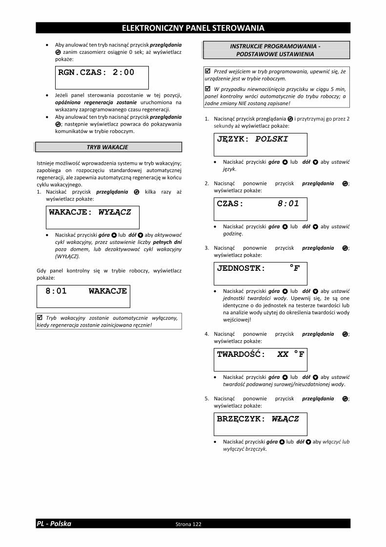
ELEKTRONICZNY PANEL STEROWANIA
PL - Polska Strona 122
• Aby anulować ten tryb nacisnąć przycisk przeglądania
zanim czasomierz osiągnie 0 sek; aż wyświetlacz pokaże:
• Jeżeli panel sterowania pozostanie w tej pozycji, opóźniona regeneracja zostanie uruchomiona na wskazany zaprogramowanego czasu regeneracji.
• Aby anulować ten tryb nacisnąć przycisk przeglądania
; następnie wyświetlacz powraca do pokazywania komunikatów w trybie roboczym.
TRYB WAKACJE
Istnieje możliwość wprowadzenia systemu w tryb wakacyjny; zapobiega on rozpoczęciu standardowej automatycznej regeneracji, ale zapewnia automatyczną regenerację w końcu cyklu wakacyjnego. 1. Naciskać przycisk przeglądania kilka razy aż
wyświetlacz pokaże:
• Naciskać przyciski góra lub dół aby aktywować cykl wakacyjny, przez ustawienie liczby pełnych dni poza domem, lub dezaktywować cykl wakacyjny (WYŁĄCZ).
Gdy panel kontrolny się w trybie roboczy, wyświetlacz pokaże:
Tryb wakacyjny zostanie automatycznie wyłączony, kiedy regeneracja zostanie zainicjowana ręcznie!
INSTRUKCJE PROGRAMOWANIA - PODSTAWOWE USTAWIENIA
Przed wejściem w tryb programowania, upewnić się, że urządzenie jest w trybie roboczym.
W przypadku niewnaciśnięcia przycisku w ciągu 5 min, panel kontrolny wróci automatycznie do trybu roboczy; a żadne zmiany NIE zostaną zapisane!
1. Nacisnąć przycisk przeglądania i przytrzymaj go przez 2
sekundy aż wyświetlacz pokaże:
• Naciskać przyciski góra lub dół aby ustawić język.
2. Nacisnąć ponownie przycisk przeglądania ;
wyświetlacz pokaże:
• Naciskać przyciski góra lub dół aby ustawić godzinę.
3. Nacisnąć ponownie przycisk przeglądania ;
wyświetlacz pokaże:
• Naciskać przyciski góra lub dół aby ustawić jednostki twardości wody. Upewnij się, że są one identyczne o do jednostek na testerze twardości lub na analizie wody użytej do określenia twardości wody wejściowej!
4. Nacisnąć ponownie przycisk przeglądania ;
wyświetlacz pokaże:
• Naciskać przyciski góra lub dół aby ustawić twardość podawanej surowej/nieuzdatnionej wody.
5. Nacisnąć ponownie przycisk przeglądania ;
wyświetlacz pokaże:
• Naciskać przyciski góra lub dół aby włączyć lub wyłączyć brzęczyk.
RGN.CZAS: 2:00
8:01 WAKACJE
WAKACJE: WYŁĄCZ CZAS: 8:01
TWARDOŚĆ: XX °F
JEDNOSTK: °F
JĘZYK: POLSKI
BRZĘCZYK: WŁĄCZ

ELEKTRONICZNY PANEL STEROWANIA
Strona 123 PL - Polska
6. Nacisnąć ponownie przycisk przeglądania ; wyświetlacz pokaże:
• Naciskać przyciski góra lub dół , aby zachować program w NOVRAM® i wyjść z poziomu programowania.
INSTRUKCJE PROGRAMOWANIA - PARAMETRY KONFIGURACYJNE
Przed wejściem w tryb programowania, upewnić się, że urządzenie jest w trybie roboczym.
Wszystkie parametry konfiguracji w niniejszym urządzeniu zostały wstępnie ustawione w fabryce, aby zaoferować optymalną wydajność szerokim zakresie zastosowań i sytuacji. Jednakże, konieczna lub pożądana okazać się może zmiana któregokolwiek z tych parametrów, w celu zoptymalizowania osiągów urządzenia lub do zaadaptowania go do specjalnych wymogów instalacji.
W przypadku niewnaciśnięcia przycisku w ciągu 5 min, panel kontrolny wróci automatycznie do trybu roboczy; a żadne zmiany NIE zostaną zapisane!
tylko dla PF-SOF1-SIM & PF-SOF1,5-SIM
1. Nacisnąć przycisk przeglądania i przytrzymać przez 6
sekund aż wyświetlacz pokaże: 2. W ciągu 10 sek. nacisnąć przycisk góra ; wyświetlacz
pokaże:
• Naciskać przyciski góra lub dół aby ustawić jednostki miary (metryczne lub Angiel-US).
3. Nacisnąć ponownie przycisk przeglądania ;
wyświetlacz pokaże:
• Naciskać przyciski góra lub dół aby aktywować funkcję przypominania o konserwacji poprzez ustawienie interwału konserwacji lub wyłączyć funkcję przypominania o konserwacji.
4. Nacisnąć ponownie przycisk przeglądania ;
wyświetlacz pokaże:
• Naciskać przyciski góra lub dół aby ustawić zdolność wymienną na litr żywicy.
5. Nacisnąć ponownie przycisk przeglądania ;
wyświetlacz pokaże:
• Naciskać przyciski góra lub dół aby aby ustawić współczynnik korekcyjny (%/rok) w celu zrekompensowania utraty zdolności jonowymiennych żywicy wskutek starzenia.
WYDAJ:5.5°F M3/L
PRZEGLĄD SYSTEMU
JEDNO:METRYCZNE
SERWCZAS: 24MIES
UPŁCZASU.: 2.0%
WYJŚCIE
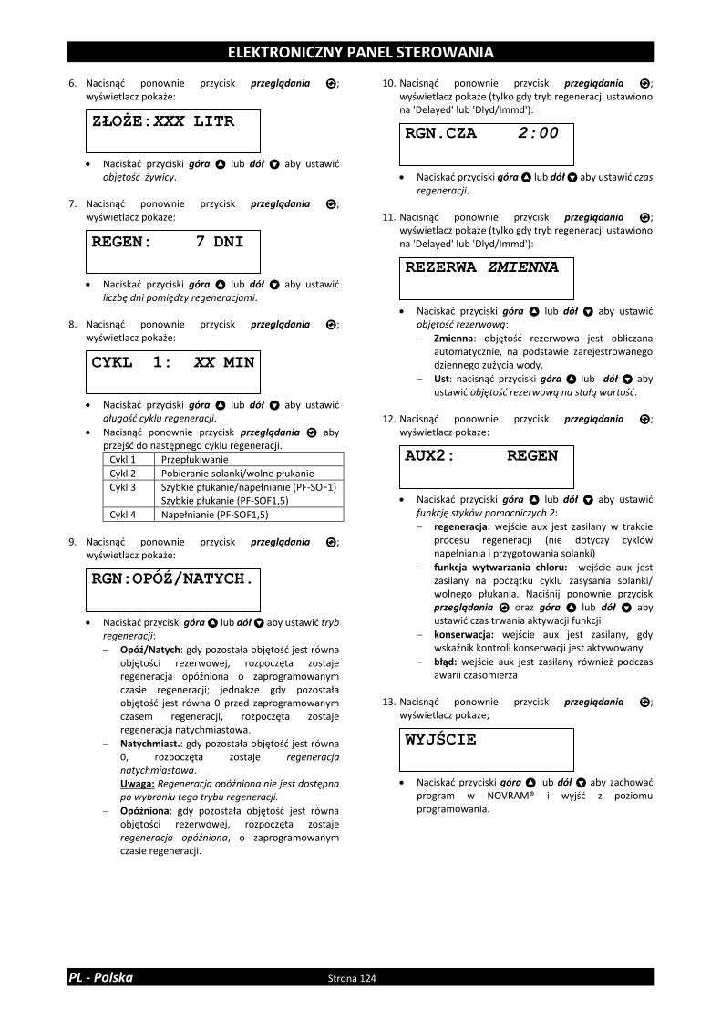
ELEKTRONICZNY PANEL STEROWANIA
PL - Polska Strona 124
6. Nacisnąć ponownie przycisk przeglądania ; wyświetlacz pokaże:
• Naciskać przyciski góra lub dół aby ustawić objętość żywicy.
7. Nacisnąć ponownie przycisk przeglądania ;
wyświetlacz pokaże:
• Naciskać przyciski góra lub dół aby ustawić liczbę dni pomiędzy regeneracjami.
8. Nacisnąć ponownie przycisk przeglądania ;
wyświetlacz pokaże:
• Naciskać przyciski góra lub dół aby ustawić długość cyklu regeneracji.
• Nacisnąć ponownie przycisk przeglądania aby przejść do następnego cyklu regeneracji.
Cykl 1 Przepłukiwanie
Cykl 2 Pobieranie solanki/wolne płukanie
Cykl 3 Szybkie płukanie/napełnianie (PF-SOF1) Szybkie płukanie (PF-SOF1,5)
Cykl 4 Napełnianie (PF-SOF1,5)
9. Nacisnąć ponownie przycisk przeglądania ;
wyświetlacz pokaże:
• Naciskać przyciski góra lub dół aby ustawić tryb regeneracji:
Opóź/Natych: gdy pozostała objętość jest równa objętości rezerwowej, rozpoczęta zostaje regeneracja opóźniona o zaprogramowanym czasie regeneracji; jednakże gdy pozostała objętość jest równa 0 przed zaprogramowanym czasem regeneracji, rozpoczęta zostaje regeneracja natychmiastowa.
Natychmiast.: gdy pozostała objętość jest równa 0, rozpoczęta zostaje regeneracja natychmiastowa. Uwaga: Regeneracja opóźniona nie jest dostępna po wybraniu tego trybu regeneracji.
Opóźniona: gdy pozostała objętość jest równa objętości rezerwowej, rozpoczęta zostaje regeneracja opóźniona, o zaprogramowanym czasie regeneracji.
10. Nacisnąć ponownie przycisk przeglądania ; wyświetlacz pokaże (tylko gdy tryb regeneracji ustawiono na 'Delayed' lub 'Dlyd/Immd'):
• Naciskać przyciski góra lub dół aby ustawić czas regeneracji.
11. Nacisnąć ponownie przycisk przeglądania ;
wyświetlacz pokaże (tylko gdy tryb regeneracji ustawiono na 'Delayed' lub 'Dlyd/Immd'):
• Naciskać przyciski góra lub dół aby ustawić objętość rezerwową:
Zmienna: objętość rezerwowa jest obliczana automatycznie, na podstawie zarejestrowanego dziennego zużycia wody.
Ust: nacisnąć przyciski góra lub dół aby ustawić objętość rezerwową na stałą wartość.
12. Nacisnąć ponownie przycisk przeglądania ;
wyświetlacz pokaże:
• Naciskać przyciski góra lub dół aby ustawić funkcję styków pomocniczych 2:
regeneracja: wejście aux jest zasilany w trakcie procesu regeneracji (nie dotyczy cyklów napełniania i przygotowania solanki)
funkcja wytwarzania chloru: wejście aux jest zasilany na początku cyklu zasysania solanki/ wolnego płukania. Naciśnij ponownie przycisk przeglądania oraz góra lub dół aby ustawić czas trwania aktywacji funkcji
konserwacja: wejście aux jest zasilany, gdy wskaźnik kontroli konserwacji jest aktywowany
błąd: wejście aux jest zasilany również podczas awarii czasomierza
13. Nacisnąć ponownie przycisk przeglądania ;
wyświetlacz pokaże;
• Naciskać przyciski góra lub dół aby zachować program w NOVRAM® i wyjść z poziomu programowania.
CYKL 1: XX MIN
RGN.CZA 2:00
WYJŚCIE
ZŁOŻE:XXX LITR
REGEN: 7 DNI
RGN:OPÓŹ/NATYCH.
REZERWA ZMIENNA
AUX2: REGEN

ELEKTRONICZNY PANEL STEROWANIA
Strona 125 PL - Polska
tylko dla PF-SOF1-ALT & PF-SOF1,5-ALT
Każdy z dwóch systemów Simplex, które składają się na system Duplex, musi być nastawiony indywidualnie; program NIEKONIECZNIE musi być taki sam dla obydwu systemów pojedynczych!
1. Nacisnąć przycisk przeglądania i przytrzymać przez 6
sekund aż wyświetlacz pokaże: 2. W ciągu 10 sek. nacisnąć przycisk góra ; wyświetlacz
pokaże:
• Naciskać przyciski góra lub dół aby ustawić jednostki miary (metryczne lub Angiel-US).
3. Nacisnąć ponownie przycisk przeglądania ;
wyświetlacz pokaże:
• Naciskać przyciski góra lub dół aby aktywować funkcję przypominania o konserwacji poprzez ustawienie interwału konserwacji lub wyłączyć funkcję przypominania o konserwacji.
4. Nacisnąć ponownie przycisk przeglądania ;
wyświetlacz pokaże:
• Naciskać przyciski góra lub dół aby ustawić zdolność wymienną na litr żywicy.
5. Nacisnąć ponownie przycisk przeglądania ;
wyświetlacz pokaże:
• Naciskać przyciski góra lub dół aby aby ustawić współczynnik korekcyjny (%/rok) w celu zrekompensowania utraty zdolności jonowymiennych żywicy wskutek starzenia.
6. Nacisnąć ponownie przycisk przeglądania ;
wyświetlacz pokaże:
• Naciskać przyciski góra lub dół aby ustawić objętość żywicy.
7. Nacisnąć ponownie przycisk przeglądania ; wyświetlacz pokaże:
• Naciskać przyciski góra lub dół aby ustawić liczbę dni pomiędzy regeneracjami.
8. Nacisnąć ponownie przycisk przeglądania ;
wyświetlacz pokaże:
• Naciskać przyciski góra lub dół aby ustawić długość cyklu regeneracji.
• Nacisnąć ponownie przycisk przeglądania aby przejść do następnego cyklu regeneracji.
Cykl 1 Przepłukiwanie
Cykl 2 Pobieranie solanki/wolne płukanie
Cykl 3 Szybkie płukanie/napełnianie (PF-SOF1) Szybkie płukanie (PF-SOF1,5)
Cykl 4 Napełnianie (PF-SOF1,5)
9. Nacisnąć ponownie przycisk przeglądania ;
wyświetlacz pokaże:
• Naciskać przyciski góra lub dół aby ustawić funkcję styków pomocniczych 2:
regeneracja: wejście aux jest zasilany w trakcie procesu regeneracji (nie dotyczy cyklów napełniania i przygotowania solanki)
funkcja wytwarzania chloru: wejście aux jest zasilany na początku cyklu zasysania solanki/ wolnego płukania. Naciśnij ponownie przycisk przeglądania oraz góra lub dół aby ustawić czas trwania aktywacji funkcji
konserwacja: wejście aux jest zasilany, gdy wskaźnik kontroli konserwacji jest aktywowany
błąd: wejście aux jest zasilany również podczas awarii czasomierza
10. Nacisnąć ponownie przycisk przeglądania ;
wyświetlacz pokaże:
• Naciskać przyciski góra lub dół aby zachować program w NOVRAM® i wyjść z poziomu programowania.
11. Powtórzyć kroki 1-10 dla obu systemów Simplex.
WYJŚCIE
CYKL 1: XX MIN
ZŁOŻE:XXX LITR
WYDAJ:5.5°F M3/L
REGEN: 7 DNI
PRZEGLĄD SYSTEMU
JEDNO:METRYCZNE
SERWCZAS: 24MIES
UPŁCZASU.: 2.0%
AUX2: REGEN

ELEKTRONICZNY PANEL STEROWANIA
PL - Polska Strona 126
tylko dla PF-SOF1-PRL & PF-SOF1,5-PRL
Każdy z dwóch systemów Simplex, które składają się na system Duplex, musi być nastawiony indywidualnie; program NIEKONIECZNIE musi być taki sam dla obydwu systemów pojedynczych!
1. Nacisnąć przycisk przeglądania i przytrzymać przez 6
sekund aż wyświetlacz pokaże: 2. W ciągu 10 sek. nacisnąć przycisk góra ; wyświetlacz
pokaże:
• Naciskać przyciski góra lub dół aby ustawić jednostki miary (metryczne lub Angiel-US).
3. Nacisnąć ponownie przycisk przeglądania ;
wyświetlacz pokaże:
• Naciskać przyciski góra lub dół aby aktywować funkcję przypominania o konserwacji poprzez ustawienie interwału konserwacji lub wyłączyć funkcję przypominania o konserwacji.
4. Nacisnąć ponownie przycisk przeglądania ;
wyświetlacz pokaże:
• Naciskać przyciski góra lub dół aby ustawić zdolność wymienną na litr żywicy.
5. Nacisnąć ponownie przycisk przeglądania ;
wyświetlacz pokaże:
• Naciskać przyciski góra lub dół aby aby ustawić współczynnik korekcyjny (%/rok) w celu zrekompensowania utraty zdolności jonowymiennych żywicy wskutek starzenia.
6. Nacisnąć ponownie przycisk przeglądania ;
wyświetlacz pokaże:
• Naciskać przyciski góra lub dół aby ustawić objętość żywicy.
7. Nacisnąć ponownie przycisk przeglądania ; wyświetlacz pokaże:
• Naciskać przyciski góra lub dół aby ustawić liczbę dni pomiędzy regeneracjami.
8. Nacisnąć ponownie przycisk przeglądania ;
wyświetlacz pokaże:
• Naciskać przyciski góra lub dół aby ustawić długość cyklu regeneracji.
• Nacisnąć ponownie przycisk przeglądania aby przejść do następnego cyklu regeneracji.
Cykl 1 Przepłukiwanie
Cykl 2 Pobieranie solanki/wolne płukanie
Cykl 3 Szybkie płukanie/napełnianie (PF-SOF1) Szybkie płukanie (PF-SOF1,5)
Cykl 4 Napełnianie (PF-SOF1,5)
9. Nacisnąć ponownie przycisk przeglądania ;
wyświetlacz pokaże:
• Naciskać przyciski góra lub dół aby ustawić tryb regeneracji:
Natychmiast.: gdy pozostała objętość jest równa 0, rozpoczęta zostaje regeneracja natychmiastowa. Uwaga: Regeneracja opóźniona nie jest dostępna po wybraniu tego trybu regeneracji.
Opóź/Natych: gdy pozostała objętość jest równa objętości rezerwowej, rozpoczęta zostaje regeneracja opóźniona o zaprogramowanym czasie regeneracji; jednakże gdy pozostała objętość jest równa 0 przed zaprogramowanym czasem regeneracji, rozpoczęta zostaje regeneracja natychmiastowa.
Opóźniona: gdy pozostała objętość jest równa objętości rezerwowej, rozpoczęta zostaje regeneracja opóźniona, o zaprogramowanym czasie regeneracji.
10. Nacisnąć ponownie przycisk przeglądania ;
wyświetlacz pokaże (tylko gdy tryb regeneracji ustawiono na 'Delayed' lub 'Dlyd/Immd'):
• Naciskać przyciski góra lub dół aby ustawić czas regeneracji.
RGN.CZA 2:00
RGN:NATYCHMIAST.
CYKL 1: XX MIN
ZŁOŻE:XXX LITR
WYDAJ:5.5°F M3/L
REGEN: 7 DNI
PRZEGLĄD SYSTEMU
JEDNO:METRYCZNE
SERWCZAS: 24MIES
UPŁCZASU.: 2.0%

ELEKTRONICZNY PANEL STEROWANIA
Strona 127 PL - Polska
11. Nacisnąć ponownie przycisk przeglądania ; wyświetlacz pokaże (tylko gdy tryb regeneracji ustawiono na 'Delayed' lub 'Dlyd/Immd'):
• Naciskać przyciski góra lub dół aby ustawić objętość rezerwową:
Variable: objętość rezerwowa jest obliczana automatycznie, na podstawie zarejestrowanego dziennego zużycia wody.
Ust: nacisnąć góra lub dół aby ustawić objętość rezerwową na stałą wartość.
12. Nacisnąć ponownie przycisk przeglądania ;
wyświetlacz pokaże:
• Naciskać przyciski góra lub dół aby ustawić funkcję styków pomocniczych 2:
regeneracja: wejście aux jest zasilany w trakcie procesu regeneracji (nie dotyczy cyklów napełniania i przygotowania solanki)
funkcja wytwarzania chloru: wejście aux jest zasilany na początku cyklu zasysania solanki/ wolnego płukania. Naciśnij ponownie przycisk przeglądania oraz góra lub dół aby ustawić czas trwania aktywacji funkcji
konserwacja: wejście aux jest zasilany, gdy wskaźnik kontroli konserwacji jest aktywowany
błąd: wejście aux jest zasilany również podczas awarii czasomierza
13. Nacisnąć ponownie przycisk przeglądania ;
wyświetlacz pokaże:
• Naciskać przyciski góra lub dół aby zachować program w NOVRAM® i wyjść z poziomu programowania.
14. Powtórzyć kroki 1-13 dla obu systemów Simplex.
WYJŚCIE
REZERWA ZMIENNA
AUX2: REGEN

KONSERWACJA
PL - Polska Strona 128
ZALECENIE
Pomimo niezawodności urządzenia, zaleca się, aby urządzenie było serwisowane przez kompetentny i odpowiednio przeszkolony personel. Będzie on w stanie określić odpowiednią częstotliwość serwisów dla urządzenia, biorąc pod uwagę specyfikę jego użytkowania. Zalety wykonywania regularnych serwisów, są następujące:
• regularne sprawdzanie jakości wody wejściowej, ciśnienia itp);
• regularna kontrola regulacji ustawień urządzenia, w celu zagwarantowania najwyższej wydajności urządzenia;
• minimalizacja ryzyka niespodziewanych usterek. Aby uzyskać więcej informacji należy skontaktować się ze sprzedawcą. Zapraszamy do odwiedzenia naszej strony internetowej.
REGULARNE PUNKTY KONTROLNE
W celu sprawdzenia, czy urządzenie działa prawidłowo, użytkownik powinien wykonać kilka podstawowych czynności kontrolnych, na podstawie następujących punktów: 1. Sprawdzić ustawienia panelu sterowania. 2. Zmierzyć twardość wody przed i za urządzeniem. 3. Sprawdzić wąż odprowadzania popłuczyn; nie powinno
być w nim przepływu wody (chyba, że urządzenie jest w trakcie regeneracji).
4. Sprawdzić wąż odprowadzający wodę z przelewu zbiornika solanki; nie powinno być w nim przepływu wody.
5. Sprawdzić miejsce dookoła urządzenia; nie powinno być żadnych wycieków.
OBEJŚCIE URZĄDZENIE
Czasami konieczne może być ominięcie jednostki tzn. izolowanie jej z systemu dystrybucji wody np.:
• w przypadku nagłego problemu technicznego;
• gdy nie jest konieczne dostarczanie uzdatnionej wody do urządzenia.
OBEJŚCIE FABRYCZNE (opcjonalne) (tylko dla PF-SOF1)
Zdjęcie 15.a
POZYCJA ROBOCZA = zawór wlotowy do urządzenia jest OTWARTY ❖ = zawór wylotowy ze urządzenia jest OTWARTY
Zdjęcie 15.b
POZYCJA OBEJŚCIA = zawór wlotowy do urządzenia jest ZAMKNIĘTY ❖ = zawór wylotowy ze urządzenia jest ZAMKNIĘTY
Zdjęcie 15.c
POZYCJA KONSERWACJA = zawór wlotowy do urządzenia jest OTWARTY ❖ = zawór wylotowy ze urządzenia jest ZAMKNIĘTY
SÓL UZDATNIAJĄCA DO WODY
Urządzenie potrzebuje 'solanki' stosowanej do okresowych regeneracji. Roztwór solanki przygotowywany jest z soli
uzdatniającej i wody, która jest dozowana automatycznie do zbiornika solanki przy użyciu zaworu sterującego. Użytkownik powinien upewnić się, że zbiornik solanki jest zawsze napełniony solą uzdatniającą do wody. Dlatego powinien regularnie sprawdzać poziom soli w zbiorniku solanki i, jeżeli jest to konieczne, uzupełniać niedobory soli. Najlepiej, aby poziom soli uzdatniającej znajdującej się wewnątrz zbiornika solanki był utrzymywany pomiędzy 1/3 a 2/3. Niższy poziom soli uzdatniającej może powodować niewystarczające nasycenie solanki, a co za tym idzie stratę wydajności zmiękczacza. Wyższy od podanego poziom soli uzdatniającej może powodować zbrylanie się soli (twarde skorupy lub bryły soli w zbiorniku solanki). Jeżeli podejrzewa się, że ma miejsce zbrylanie soli:
• ostrożnie opukać zewnętrzną stronę obudowy zbiornika solanki, aby rozkruszyć zlepione bryły soli;
• przy użyciu szczotki (lub podobnego, tępego narzędzia) ostrożnie poruszyć solą, aby ją rozkruszyć;
• nalać z góry ciepłą wodę na sól, aby spowodować jej rozpuszczenie.
SUBSTANCJA CZYSZCZĄCA ZŁOŻE ŻYWICY
Inne zanieczyszczenia (np. żelazo) obecne w podawanej wodzie mogą zanieczyszczać złoże żywicy, a co za tym idzie powodować stratę wydajności zmiękczacza. Do dokładnego, okresowego czyszczenia złoża należy użyć zatwierdzonego środka czyszczącego do złoża żywicy.
ODKAŻANIE URZĄDZENIE
Niniejszy urządzenie wykonany jest z materiałów o najwyższej jakości i zmontowany w bezpiecznych warunkach, aby zapewnić jego czystość i higieniczność. Jeżeli urządzenie to jest odpowiednio zainstalowane i eksploatowane, to jego działanie nie zanieczyści dopływu wody. Jednakże, tak jak w przypadku każdego innego urządzenia włączonego do systemu dystrybucji wody, możliwe jest rozmnażanie się bakterii, zwłaszcza w 'wodzie nieruchomej'. Ponieważ urządzenie jest sterowany czasomierzem, to będzie okresowo wykonywał przemywanie złoża żywicznego, nawet gdy woda nie jest pobierana. Jeżeli zasilanie elektryczne urządzenia jest rozłączone przez dłuższy okres czasu, zalecamy, aby po ponownym załączeniu zasilania, manualnie zainicjować całkowitą regenerację.
NORMALNIE ZAMKNIĘTY ZAWORY SERWISOWE (tylko dla PF-SOF1-ALT & PF-SOF1,5-ALT)
Zdjęcie 16
= automatycznie obsługiwany = normalnie zamknięty ❖ = ręcznie obsługiwane = stale otwarte Normalnie zamknięty zawór serwisowy na wyjściu każdego z systemów Simplex jest otwarty tylko wtedy, gdy jest on zasilany. Aby otworzyć go ręcznie (np. w przypadku awarii zasilania), przekręć białą cewkę w kierunku przeciwnym do ruchu wskazówek zegara.

PRZEGLĄD SKŁADNIKÓW
Strona 129 PL - Polska
Model Objętość
żywicy PN
Zawór sterujący, z transformator, zestawem złączeniowym 1” BSP GZ
Kable InterConnect
Zawory Serwisowe 1” BSP GW
Zbiornik ciśnieniowy, z zespołem dystryb.
Żywica (worek 25 ltr)
ltr model # # model # model # #
PF-
SOF1
-SIM
25 35810 2400VS/J4JB/PRL1 1 0 / 0 10x35 1 1
50 35811 2400VS/J1KD/PRL1 1 0 / 0 12x48 1 2
75 35812 2400VS/J1LD/PRL1 1 0 / 0 13x54 1 3
100 35813 2400VS/J2MD/PRL1 1 0 / 0 14x65 1 4
150 35814 2400VS/J2ND/PRL1 1 0 / 0 16x65 1 6
PF-
SOF1
-ALT
2 x 25 35815 2400VS/J4JB/ALT 2 1 NZ (1) 2 10x35 2 2
2 x 50 35816 2400VS/J1KD/ALT 2 1 NZ (1) 2 12x48 2 4
2 x 75 35817 2400VS/J1LD/ALT 2 1 NZ (1) 2 13x54 2 6
2 x 100 35818 2400VS/J2MD/ALT 2 1 NZ (1) 2 14x65 2 8
2 x 150 35819 2400VS/J2ND/ALT 2 1 NZ (1) 2 16x65 2 12
PF-
SOF1
-PR
L
2 x 25 35820 2400VS/J4JB/PRL1 2 1 NO (2) 2 10x35 2 2
2 x 50 35821 2400VS/J1KD/PRL1 2 1 NO (2) 2 12x48 2 4
2 x 75 35822 2400VS/J1LD/PRL1 2 1 NO (2) 2 13x54 2 6
2 x 100 35823 2400VS/J2MD/PRL1 2 1 NO (2) 2 14x65 2 8
2 x 150 35824 2400VS/J2ND/PRL1 2 1 NO (2) 2 16x65 2 12
(1) NZ = Normalnie Zamknięty (2) NO = Normalnie Otwarty
Model Objętość
żywicy PN
Zawór sterujący, z transformator, zestawem złączeniowym 1,5” BSP GZ
Kable InterConnect
Zawory Serwisowe 1,5” BSP GW
Zbiornik ciśnieniowy, z zespołem dystryb.
Żywica (worek 25 ltr)
ltr model # # model # model ltr #
PF-
SOF1
,5-S
IM
75 35825 EV1.5VS/J/5A/40/12 1 0 / 0 13x54 1 3
100 35826 EV1.5VS/J/5A/50/12 1 0 / 0 14x65 1 4
150 35827 EV1.5VS/J/5A/60/12 1 0 / 0 16x65 1 6
200 35828 EV1.5VS/J/5/80/20 1 0 / 0 18x65 1 8
250 35829 EV1.5VS/J/5/100/20 1 0 / 0 21x62 1 10
350 35830 EV1.5VS/J/6/150/20 1 0 / 0 24x72 1 14
500 35831 EV1.5VS/J/6/200/20 1 0 / 0 30x72 1 20
PF-
SOF1
,5-A
LT
2 x 75 35832 EV1.5VS/J/5A/40/12/ALT 2 1 NZ (1) 2 13x54 2 6
2 x 100 35833 EV1.5VS/J/5A/50/12/ALT 2 1 NZ (1) 2 14x65 2 8
2 x 150 35834 EV1.5VS/J/5A/60/12/ALT 2 1 NZ (1) 2 16x65 2 12
2 x 200 35835 EV1.5VS/J/5/80/20/ALT 2 1 NZ (1) 2 18x65 2 16
2 x 250 35836 EV1.5VS/J/5/100/20/ALT 2 1 NZ (1) 2 21x62 2 20
2 x 350 35837 EV1.5VS/J/6/150/20/ALT 2 1 NZ (1) 2 24x72 2 28
2 x 500 35838 EV1.5VS/J/6/200/20/ALT 2 1 NZ (1) 2 30x72 2 40
PF-
SOF1
,5-P
RL
2 x 75 35839 EV1.5VS/J/5A/40/12 2 1 NO (2) 2 13x54 2 6
2 x 100 35840 EV1.5VS/J/5A/50/12 2 1 NO (2) 2 14x65 2 8
2 x 150 35841 EV1.5VS/J/5A/60/12 2 1 NO (2) 2 16x65 2 12
2 x 200 35842 EV1.5VS/J/5/80/20 2 1 NO (2) 2 18x65 2 16
2 x 250 35843 EV1.5VS/J/5/100/20 2 1 NO (2) 2 21x62 2 20
2 x 350 35844 EV1.5VS/J/6/150/20 2 1 NO (2) 2 24x72 2 28
2 x 500 35845 EV1.5VS/J/6/200/20 2 1 NO (2) 2 30x72 2 40
(1) NZ = Normalnie Zamknięty (2) NO = Normalnie Otwarty

DANE TECHNICZNE - PF-SOF1
PL - Polska Strona 130
Specyfikacja techniczna:
(1) Dostarczany z transformatorem 24 VDC
Osiągi @ ciśnienie robocze 3 bar(2): (2) Wielkości przybliżone, osiągi zależą od warunków roboczych i jakości wody
Model PF-SOF1-SIM / PF-SOF1-ALT / PF-SOF1-PRL
Żywica (ltr) 25 50 75 100 150
Ciśnienie robocze min./maks. (bar) 1,4/8,3
Temperatura robocza min./maks. (°C) 2/48
Złącze elektryczne (V/Hz) 230/50(1)
Maks. pobór mocy Simplex/Duplex (VA) 8
Przyłącze hydrauliczne wlot/wylot 1” BSP GZ
Przyłącze hydrauliczne spust 19 mm wąż
Przyłącze hydrauliczne zbiornik solanki ⅜” złączka Jaco
Zbiornik ciśnieniowy 10x35 12x48 13x54 14x65 16x65
Model PF-SOF1-SIM
Żywica (ltr) 25 50 75 100 150
Nominalna zdolność wymienna (m³x°f) 138 275 413 550 825
Nominalna zdolność wymienna (m³x°d) 78 155 233 310 465
Przepływ roboczy @∆p 1 bar (m³/hr) 3,4 3,4 3,5 3,5 3,6
Zużycie soli na regenerację (kg) 3,8 7,5 11,3 15,0 22,5
Zużycie wody płuczącej na regen. (ltr) 165 285 400 540 780
Maks. przepływ popłuczyn (ltr/min) 9,8 13,2 15,1 18,9 22,7
Model PF-SOF1-ALT
Żywica (ltr) 2x25 2x50 2x75 2x100 2x150
Nominalna zdolność wymienna (m³x°f) 275 550 825 1.100 1.650
Nominalna zdolność wymienna (m³x°d) 155 310 465 620 930
Przepływ roboczy @∆p 1 bar (m³/hr) 3,4 3,4 3,5 3,5 3,6
Zużycie soli na regenerację (kg) 7,5 15,0 22,5 30,0 45,0
Zużycie wody płuczącej na regen. (ltr) 330 570 800 1.080 1.560
Maks. przepływ popłuczyn (ltr/min) 9,8 13,2 15,1 18,9 22,7
Model PF-SOF1-PRL
Żywica (ltr) 2x25 2x50 2x75 2x100 2x150
Nominalna zdolność wymienna (m³x°f) 275 550 825 1.100 1.650
Nominalna zdolność wymienna (m³x°d) 155 310 465 620 930
Przepływ roboczy @∆p 1 bar (m³/hr) 6,7 6,8 7,0 7,0 7,2
Zużycie soli na regenerację (kg) 7,5 15,0 22,5 30,0 45,0
Zużycie wody płuczącej na regen. (ltr) 330 570 800 1.080 1.560
Maks. przepływ popłuczyn (ltr/min) 9,8 13,2 15,1 18,9 22,7

DANE TECHNICZNE - PF-SOF1
Strona 131 PL - Polska
Wymiary:
Model PF-SOF1-SIM
Żywica (ltr) 25 50 75 100 150
Szerokość (mm) (W) 264 311 338 365 415
Głębokość (mm) (D) 282 311 338 365 415
Głębokość, z obejściem fabr. (mm) (D) 371 376 389 403 428
Wysokość (mm) (H) 1.059 ±10 1.394 ±10 1.560 ±10 1.836 ±10 1.833 ±10
Model PF-SOF1-ALT / PF-SOF1-PRL
Żywica (ltr) 2x25 2x50 2x75 2x100 2x150
Szerokość (mm) (W) (1) 613 707 761 815 915
Głębokość (mm) (D) 405 410 436 463 513
Wysokość (mm) (H) 1.059 ±10 1.394 ±10 1.560 ±10 1.836 ±10 1.833 ±10 (1) W oparciu o odstpie 85 mm

DANE TECHNICSZE - PF-SOF1,5
PL - Polska Strona 132
Specyfikacja techniczna:
(1) Dostarczany z transformatorem 24 VAC
Osiągi @ ciśnienie robocze 3 bar(2): (2) Wielkości przybliżone, osiągi zależą od warunków roboczych i jakości wody
Model PF-SOF1,5-SIM / PF-SOF1,5-ALT / PF-SOF1,5-PRL
Żywica (ltr) 75 100 150 200 250 350 500
Ciśnienie robocze min./maks. (bar) 1,4/8,0
Temperatura robocza min./maks. (°C) 2/48
Złącze elektryczne (V/Hz) 230/50(1)
Maks. pobór mocy Simplex/Duplex (VA) 80/2x89
Przyłącze hydrauliczne wlot/wylot 1,5” BSP GZ/GW
Przyłącze hydrauliczne spust 1” BSP GZ
Przyłącze hydrauliczne zbiornik solanki ½” złączka Jaco
Zbiornik ciśnieniowy 13x54 14x65 16x65 18x65 21x62 24x72 30x72
Model PF-SOF1,5-SIM
Żywica (ltr) 75 100 150 200 250 350 500
Nominalna zdolność wymienna (m³x°f) 413 550 825 1.100 1.375 1.925 2.750
Nominalna zdolność wymienna (m³x°d) 233 310 465 620 775 1.085 1.550
Przepływ roboczy @∆p 1 bar (m³/hr) 7,8 7,8 7,8 7,9 7,9 8,0 8,0
Zużycie soli na regenerację (kg) 11,3 15,0 22,5 30,0 37,5 52,5 75,0
Zużycie wody płuczącej na regen. (ltr) 469 578 838 1.148 1.435 2.140 3.030
Maks. przepływ popłuczyn (ltr/min) 15,2 19,0 22,7 30,3 37,9 56,8 75,7
Model PF-SOF1,5-ALT
Żywica (ltr) 2x75 2x100 2x150 2x200 2x250 2x350 2x500
Nominalna zdolność wymienna (m³x°f) 825 1.100 1.650 2.200 2.750 3.850 5.500
Nominalna zdolność wymienna (m³x°d) 465 620 930 1.240 1.550 2.170 3.100
Przepływ roboczy @∆p 1 bar (m³/hr) 7,8 7,8 7,8 7,9 7,9 8,0 8,0
Zużycie soli na regenerację (kg) 22,5 30,0 45,0 60,0 75,0 105,0 150,0
Zużycie wody płuczącej na regen. (ltr) 938 1.156 1.676 2.296 2.870 4.280 6.060
Maks. przepływ popłuczyn (ltr/min) 15,2 19,0 22,7 30,3 37,9 56,8 75,7
Model PF-SOF1,5-PRL
Żywica (ltr) 2x75 2x100 2x150 2x200 2x250 2x350 2x500
Nominalna zdolność wymienna (m³x°f) 825 1.100 1.650 2.200 2.750 3.850 5.500
Nominalna zdolność wymienna (m³x°d) 465 620 930 1.240 1.550 2.170 3.100
Przepływ roboczy @∆p 1 bar (m³/hr) 15,6 15,6 15,6 15,8 15,8 16,0 16,0
Zużycie soli na regenerację (kg) 22,5 30,0 45,0 60,0 75,0 105,0 150,0
Zużycie wody płuczącej na regen. (ltr) 938 1.156 1.676 2.296 2.870 4.280 6.060
Maks. przepływ popłuczyn (ltr/min) 15,2 19,0 22,7 30,3 37,9 56,8 75,7

DANE TECHNICSZE - PF-SOF1,5
Strona 133 PL - Polska
Wymiary:
Model PF-SOF1,5-SIM
Żywica (ltr) 75 100 150 200 250 350 500
Szerokość (mm) (W) 390 403 428 491 555 635 786
Głębokość (mm) (D) 575 575 575 595 627 667 786
Wysokość (mm) (H) 1.623 1.904 1.901 1.952 1.951 2.148 2.066
Model PF-SOF1,5-ALT / PF-SOF1,5-PRL
Żywica (ltr) 2x75 2x100 2x150 2x200 2x250 2x350 2x500
Szerokość (mm) (W) (1) 930 956 1.006 1.132 1.260 1.420 1.722
Głębokość (mm) (D) 690 690 690 706 738 778 850
Wysokość (mm) (H) 1.623 1.904 1.901 1.952 1.951 2.148 2.066 (1) W oparciu o odstpie 85 mm

DANE TECHNICZNE - PF-BTA
PL - Polska Strona 134
Specyfikacja techniczna:
Model PF-BTA
Głośność (ltr) 125 275 500 750
Przyłącze hydrauliczne zawór pływakowy wymienny: ⅜” Quick-Fit & ½” złączka Jaco
Przyłącze hydrauliczne przelew 19 mm wąż
Wymiary:
Model PF-BTA
Głośność (ltr) 125 275 500 750
Średnica (mm) (D) 540 685 875 1.030
Wysokość (mm) (H) 850 975 1.110 1.110
Wysokość przelewowy (mm) (H1) 660 825 945 945
Maks. pojemność soli (kg) 100 200 475 700


erie water treatment a division of Aquion, Inc.
www.eriewatertreatment.com