En Erco Guide 6 Lighting Technology
58
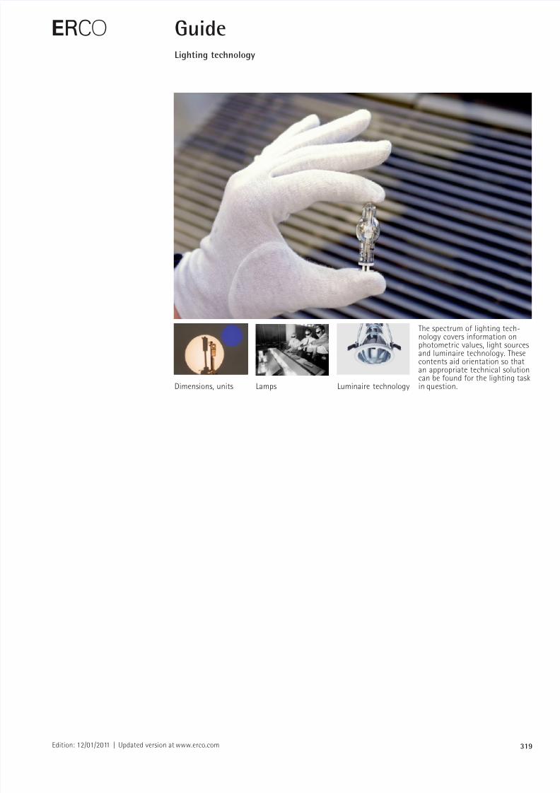
319 Edition: 12/01/2011 | Updated version at www.erco.com The spectrum of lighting tech- nology covers information on photometric values, light sources and luminaire technology. These contents aid orientation so that an appropriate technical solution can be found for the lighting task in question. Dimensions, units E Guide Lighting technology Lamps Luminaire technology
Transcript of En Erco Guide 6 Lighting Technology
8/13/2019 En Erco Guide 6 Lighting Technology
http://slidepdf.com/reader/full/en-erco-guide-6-lighting-technology 1/57
319Edition: 12/01/2011 | Updated version at www.erco.com
The spectrum of lighting tech-nology covers information onphotometric values, light sourcesand luminaire technology. Thesecontents aid orientation so thatan appropriate technical solutioncan be found for the lighting taskin question.Dimensions, units
E GuideLighting technology
Lamps Luminaire technology
8/13/2019 En Erco Guide 6 Lighting Technology
http://slidepdf.com/reader/full/en-erco-guide-6-lighting-technology 2/57
320
.10 80604020
LED
A
QT(12V)
QT
TC
T
HIT
HST
661
L
I Ap
LED
A
QT(12V)
QT
TC
T
HIT
HST
180604020
Edition: 12/01/2011 | Updated version at www.erco.com
E GuideLighting technology
Dimensions, units
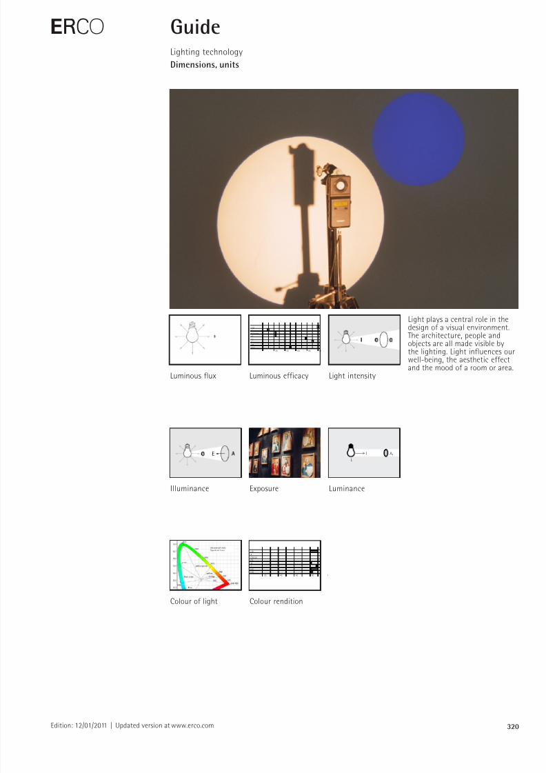
Light plays a central role in thedesign of a visual environment.The architecture, people andobjects are all made visible bythe lighting. Light influences ourwell-being, the aesthetic effectand the mood of a room or area.
Luminous flux Light intensityLuminous efficacy
Illuminance LuminanceExposure
Colour of light Colour rendition
8/13/2019 En Erco Guide 6 Lighting Technology
http://slidepdf.com/reader/full/en-erco-guide-6-lighting-technology 3/57
321
O
6 6 6
1
6 6 6 1
6 6 6 1
6 6 6 1
6 6 6 1
6 6 6 1
6661
h(lm/W) max.10080604020
LED
A
QT (12V)
QT
TC
T
HIT
HST
Edition: 12/01/2011 | Updated version at www.erco.com
Luminous flux describes thetotal light power emitted by alight source. As a rule, this radi-ant power could be expressedas emitted energy in the unit of
watts. However, this method isinadequate for describing theoptical effect of a light source,since the emitted radiation isrecorded without discriminationover the entire frequency rangeand the different spectral sensi-tivity of the eye is not considered.The inclusion of the spectral sen-sitivity of the eye results in thequantity termed lumen. A radiantflux of 1W emitted at the maxi-mum extent of spectral opticalsensitivity (photopic, 555 nm)gives a luminous flux of 683 lm.Conversely, the same radiant fluxemitted at frequency ranges of
lower sensitivity as per the V (l)results in correspondingly smallerluminous fluxes.
Luminous flux
E GuideLighting technology | Dimensions, units
Luminous flux, luminous efficacy
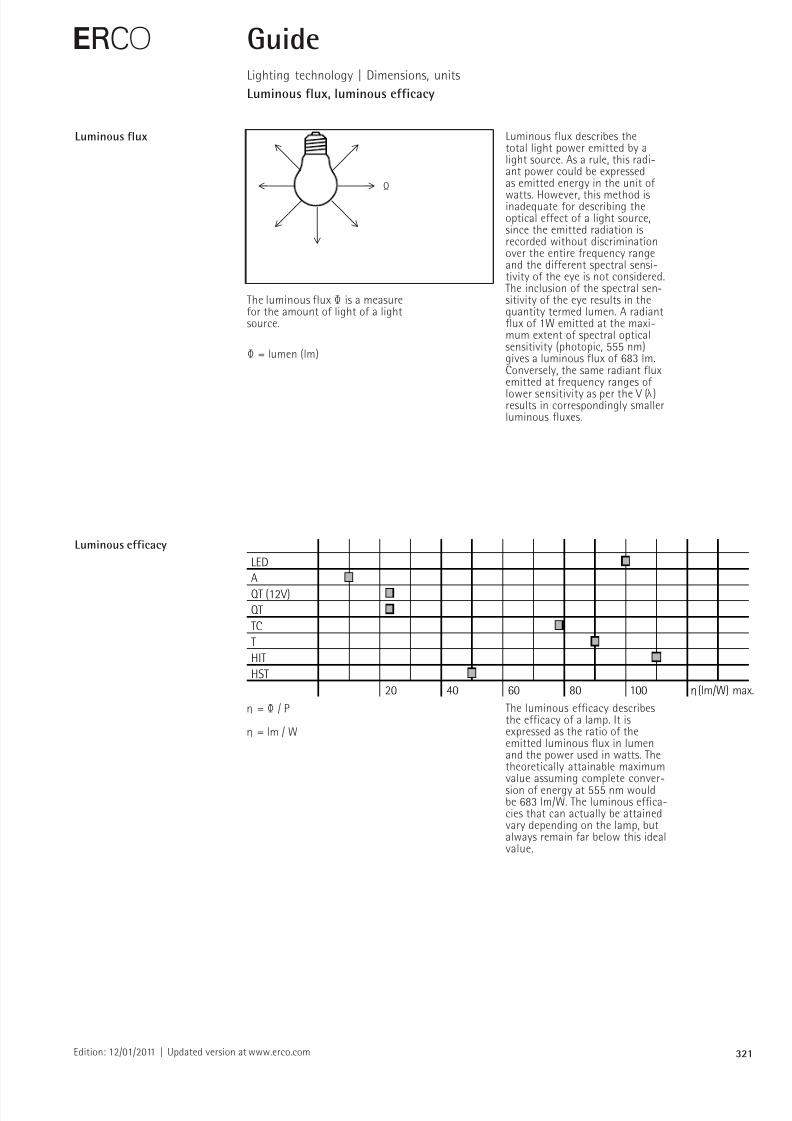
The luminous flux F is a measurefor the amount of light of a lightsource.
F = lumen (lm)
The luminous efficacy describesthe efficacy of a lamp. It isexpressed as the ratio of theemitted luminous flux in lumenand the power used in watts. Thetheoretically attainable maximumvalue assuming complete conver-sion of energy at 555 nm wouldbe 683 lm/W. The luminous effica-cies that can actually be attainedvary depending on the lamp, butalways remain far below this idealvalue.
Luminous efficacy
h = F / P
h = lm / W
8/13/2019 En Erco Guide 6 Lighting Technology
http://slidepdf.com/reader/full/en-erco-guide-6-lighting-technology 4/57
322
6 6 6
1
6 6 6 1
6 6 6 1
6 6 6 1
6 6 6 1
6 6 6 1
6661 OFI
C 90/270°
C 0/180°
0°
I
90°
Edition: 12/01/2011 | Updated version at www.erco.com
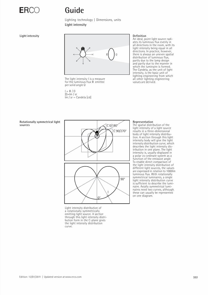
DefinitionAn ideal, point light source radi-ates its luminous flux evenly inall directions in the room, with itslight intensity being equal in all
directions. In practice, however,there is always an uneven spatialdistribution of luminous flux,partly due to the lamp designand partly due to the manner inwhich the luminaire is formed.The Candela, as the unit of lightintensity, is the basic unit oflighting engineering from whichall other lighting engineeringvalues are derived.
Light intensity
E GuideLighting technology | Dimensions, units
Light intensity
The light intensity I is a measurefor the luminous flux F emittedper solid angle O
I = F / O[I]=lm / srlm / sr = Candela [cd]
RepresentationThe spatial distribution of thelight intensity of a light sourceresults in a three-dimensionalbody of light intensity distribu-tion. A section through this lightintensity body will give the lightintensity distribution curve, whichdescribes the light intensity dis-tribution in one plane. The lightintensity is, usually displayed in
a polar co-ordinate system as afunction of the emission angle.To enable direct comparison ofthe light intensity distribution ofdifferent light sources, the valuesare expressed in relation to 1000lmluminous flux. With rotationallysymmetrical luminaires, a singlelight intensity distribution curveis sufficient to describe the lumi-naire. Axially symmetrical lumi-naires need two curves, although,these can usually be representedon one diagram.
Rotationally symmetrical lightsources
Light intensity distribution ofa rotationally symmetricallyemitting light source. A sectionthrough this light intensity distri-bution form in the C-plane givesthe light intensity distributioncurve.
8/13/2019 En Erco Guide 6 Lighting Technology
http://slidepdf.com/reader/full/en-erco-guide-6-lighting-technology 5/57
323
C 0/180°
C 90/270°
90°
I
0°
0° 30°
60°
90°
-30°
-60°
-90°
I'
I'
2
G
α
β
Y
-40° -20° 0° 20° 40°
I'
2
I'
G
αα β
Y
Edition: 12/01/2011 | Updated version at www.erco.com
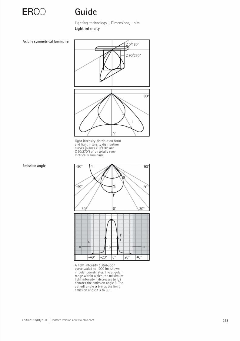
Axially symmetrical luminaire
E GuideLighting technology | Dimensions, units
Light intensity
Light intensity distribution formand light intensity distributioncurves (planes C 0/180° andC 90/270°) of an axially sym-metrically luminaire.
Emission angle
A light intensity distributioncurve scaled to 1000 lm, shownin polar coordinates. The angularrange within which the maximumlight intensity l‘ decreases to l‘/2denotes the emission angle β. Thecut-off angle α brings the limitemission angle YG to 90°.
8/13/2019 En Erco Guide 6 Lighting Technology
http://slidepdf.com/reader/full/en-erco-guide-6-lighting-technology 6/57
324
661 EF A 6 6 1
Eh E v 266 266
F
Em
A
6 1
616161
I
Ep
a
61
6 11
1
Edition: 12/01/2011 | Updated version at www.erco.com
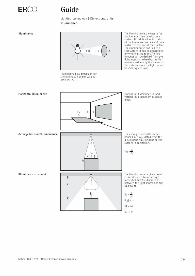
The illuminance is a measure forthe luminous flux density on asurface. It is defined as the ratioof the luminous flux incident on asurface to the size of that surface.
The illuminance is not tied to areal surface, it can be determinedanywhere in the room. The illu-minance can be derived from thelight intensity. Whereby, the illu-minance reduces by the square ofthe distance from the light source(inverse square law).
Illuminance
E GuideLighting technology | Dimensions, units
Illuminance
Illuminance E as dimension forthe luminous flux per surfacearea unit A
Horizontal illuminance Eh and
vertical illuminance Ev in indoorareas.
The average horizontal illumi-nance Em is calculated from theF luminous flux, incident on thesurface in question A.
Em = F
A
The illuminance at a given pointEp is calculated from the lightintensity l and the distance abetween the light source and thesaid point.
Ep = I a2
[Ep] = lx
[I] = cd
[a] = m
Horizontal illuminance
Average horizontal illuminance
Illuminance at a point
8/13/2019 En Erco Guide 6 Lighting Technology
http://slidepdf.com/reader/full/en-erco-guide-6-lighting-technology 7/57
325
661
L
I Ap
Eh E v
R1
R2
L 1
L 2
Edition: 12/01/2011 | Updated version at www.erco.com
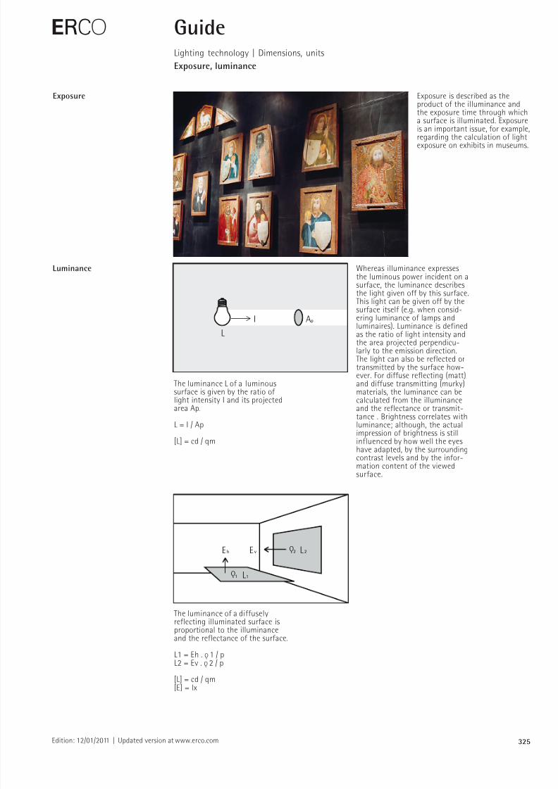
Exposure is described as theproduct of the illuminance andthe exposure time through whicha surface is illuminated. Exposureis an important issue, for example,
regarding the calculation of lightexposure on exhibits in museums.
Exposure
E GuideLighting technology | Dimensions, units
Exposure, luminance
Whereas illuminance expresses
the luminous power incident on asurface, the luminance describesthe light given off by this surface.This light can be given off by thesurface itself (e.g. when consid-ering luminance of lamps andluminaires). Luminance is definedas the ratio of light intensity andthe area projected perpendicu-larly to the emission direction.The light can also be reflected ortransmitted by the surface how-ever. For diffuse reflecting (matt)and diffuse transmitting (murky)materials, the luminance can becalculated from the illuminanceand the reflectance or transmit-tance . Brightness correlates withluminance; although, the actualimpression of brightness is stillinfluenced by how well the eyeshave adapted, by the surroundingcontrast levels and by the infor-mation content of the viewedsurface.
The luminance L of a luminoussurface is given by the ratio oflight intensity I and its projectedarea Ap.
L = I / Ap
[L] = cd / qm
Luminance
The luminance of a diffuselyreflecting illuminated surface isproportional to the illuminanceand the reflectance of the surface.
L1 = Eh . R1 / pL2 = Ev . R2 / p
[L] = cd / qm
[E] = lx
8/13/2019 En Erco Guide 6 Lighting Technology
http://slidepdf.com/reader/full/en-erco-guide-6-lighting-technology 8/57
326
0.26
0.34
0.42
0.50
0.58
0.720.32 0.48 0.640.40 0.56
50004000
3000
2000 K
1600 K
Spectral colour loci
nw
x
y
tw
ww
2500 K3300 K
6000
8000
565
580
600
620
690–780
E
123
56
4A
D 65
0.26
0.34
0.42
0.50
0.58
0.720.32 0.48 0.640.40 0.56
Spectral colour loci
x
y
Edition: 12/01/2011 | Updated version at www.erco.com
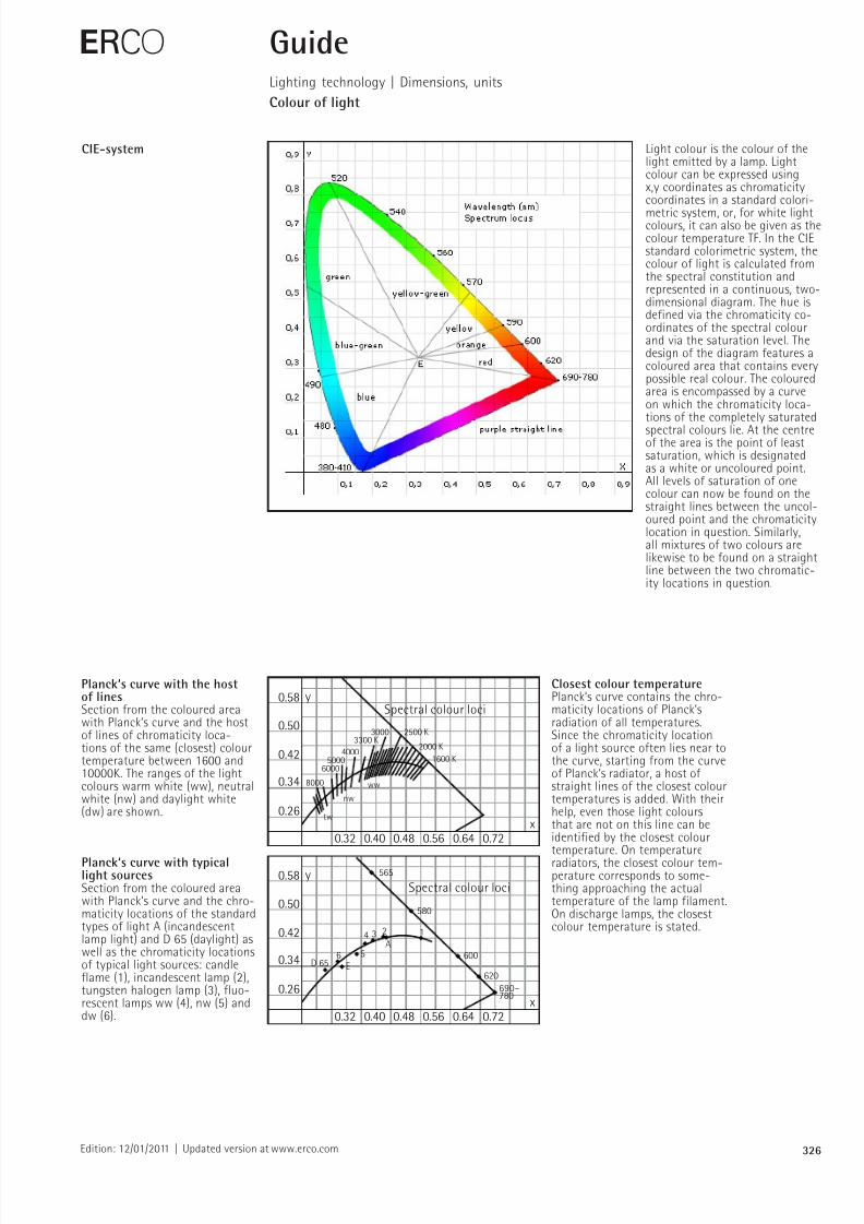
Light colour is the colour of thelight emitted by a lamp. Lightcolour can be expressed usingx,y coordinates as chromaticitycoordinates in a standard colori-
metric system, or, for white lightcolours, it can also be given as thecolour temperature TF. In the CIEstandard colorimetric system, thecolour of light is calculated fromthe spectral constitution andrepresented in a continuous, two-dimensional diagram. The hue isdefined via the chromaticity co-ordinates of the spectral colourand via the saturation level. Thedesign of the diagram features acoloured area that contains everypossible real colour. The colouredarea is encompassed by a curveon which the chromaticity loca-tions of the completely saturated
spectral colours lie. At the centreof the area is the point of leastsaturation, which is designatedas a white or uncoloured point.All levels of saturation of onecolour can now be found on thestraight lines between the uncol-oured point and the chromaticitylocation in question. Similarly,all mixtures of two colours arelikewise to be found on a straightline between the two chromatic-ity locations in question.
CIE-system
E GuideLighting technology | Dimensions, units
Colour of light
Closest colour temperaturePlanck‘s curve contains the chro-maticity locations of Planck‘sradiation of all temperatures.Since the chromaticity locationof a light source often lies near tothe curve, starting from the curveof Planck‘s radiator, a host ofstraight lines of the closest colourtemperatures is added. With theirhelp, even those light coloursthat are not on this line can beidentified by the closest colourtemperature. On temperatureradiators, the closest colour tem-perature corresponds to some-thing approaching the actualtemperature of the lamp filament.On discharge lamps, the closestcolour temperature is stated.
Planck‘s curve with the hostof linesSection from the coloured areawith Planck‘s curve and the hostof lines of chromaticity loca-tions of the same (closest) colourtemperature between 1600 and10000K. The ranges of the lightcolours warm white (ww), neutralwhite (nw) and daylight white(dw) are shown.
Planck‘s curve with typicallight sourcesSection from the coloured areawith Planck‘s curve and the chro-maticity locations of the standardtypes of light A (incandescentlamp light) and D 65 (daylight) aswell as the chromaticity locationsof typical light sources: candleflame (1), incandescent lamp (2),tungsten halogen lamp (3), fluo-rescent lamps ww (4), nw (5) anddw (6).
8/13/2019 En Erco Guide 6 Lighting Technology
http://slidepdf.com/reader/full/en-erco-guide-6-lighting-technology 9/57
327
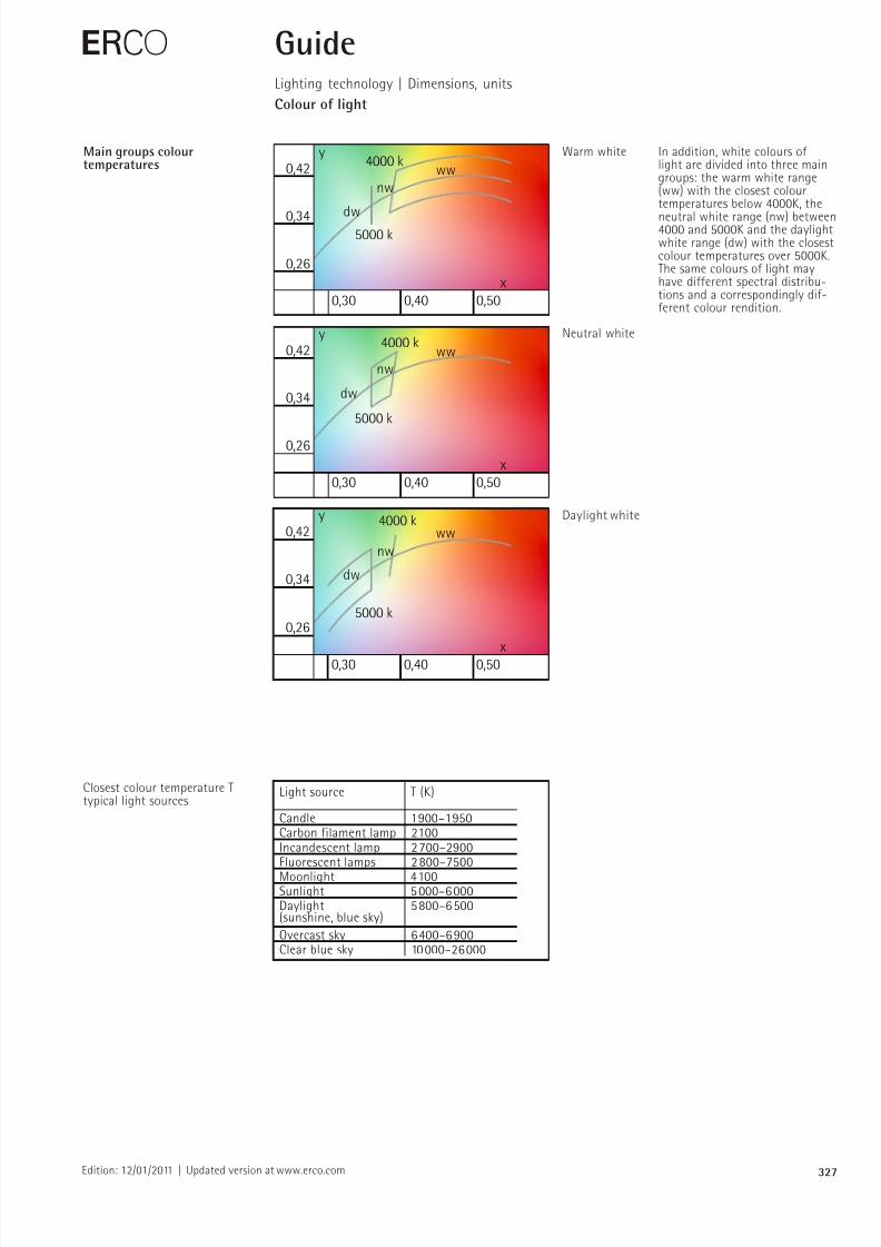
Light source T (K)
Candle 1900–1950Carbon filament lamp 2100Incandescent lamp 2700–2900Fluorescent lamps 2800–7500
Moonlight 4100Sunlight 5 000–6 000Daylight 5800–6 500(sunshine, blue sky)
Overcast sky 6400–6 900Clear blue sky 10 000–26000
0,500,400,30
0,26
0,34
0,42
x
y
dw
ww4000 k
5000 k
nw
0,500,400,30
0,26
0,34
0,42
x
y
dw
ww4000 k
5000 k
nw
0,500,400,30
0,26
0,34
0,42
x
y
dw
ww4000 k
5000 k
nw
Edition: 12/01/2011 | Updated version at www.erco.com
In addition, white colours oflight are divided into three maingroups: the warm white range(ww) with the closest colourtemperatures below 4000K, the
neutral white range (nw) between4000 and 5000K and the daylightwhite range (dw) with the closestcolour temperatures over 5000K.The same colours of light mayhave different spectral distribu-tions and a correspondingly dif-ferent colour rendition.
Main groups colourtemperatures
E GuideLighting technology | Dimensions, units
Colour of light
Warm white
Closest colour temperature Ttypical light sources
Neutral white
Daylight white
8/13/2019 En Erco Guide 6 Lighting Technology
http://slidepdf.com/reader/full/en-erco-guide-6-lighting-technology 10/57
328
LED
A
QT (12V)
QT
TC
T
HIT
HSTRa10080604020
Edition: 12/01/2011 | Updated version at www.erco.com
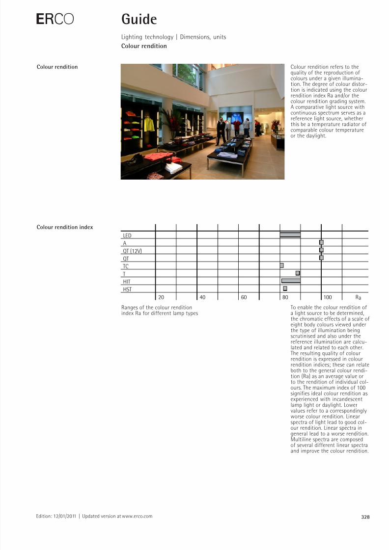
Colour rendition refers to thequality of the reproduction ofcolours under a given illumina-tion. The degree of colour distor-tion is indicated using the colour
rendition index Ra and/or thecolour rendition grading system.A comparative light source withcontinuous spectrum serves as areference light source, whetherthis be a temperature radiator ofcomparable colour temperatureor the daylight.
Colour rendition
E GuideLighting technology | Dimensions, units
Colour rendition
To enable the colour rendition ofa light source to be determined,the chromatic effects of a scale ofeight body colours viewed underthe type of illumination beingscrutinised and also under thereference illumination are calcu-lated and related to each other.The resulting quality of colourrendition is expressed in colourrendition indices; these can relateboth to the general colour rendi-tion (Ra) as an average value orto the rendition of individual col-ours. The maximum index of 100signifies ideal colour rendition asexperienced with incandescentlamp light or daylight. Lowervalues refer to a correspondinglyworse colour rendition. Linearspectra of light lead to good col-our rendition. Linear spectra ingeneral lead to a worse rendition.Multiline spectra are composedof several different linear spectraand improve the colour rendition.
Colour rendition index
Ranges of the colour renditionindex Ra for different lamp types
8/13/2019 En Erco Guide 6 Lighting Technology
http://slidepdf.com/reader/full/en-erco-guide-6-lighting-technology 11/57
329Edition: 20/02/2012 | Updated version at www.erco.com
E GuideLighting technology
Lamps
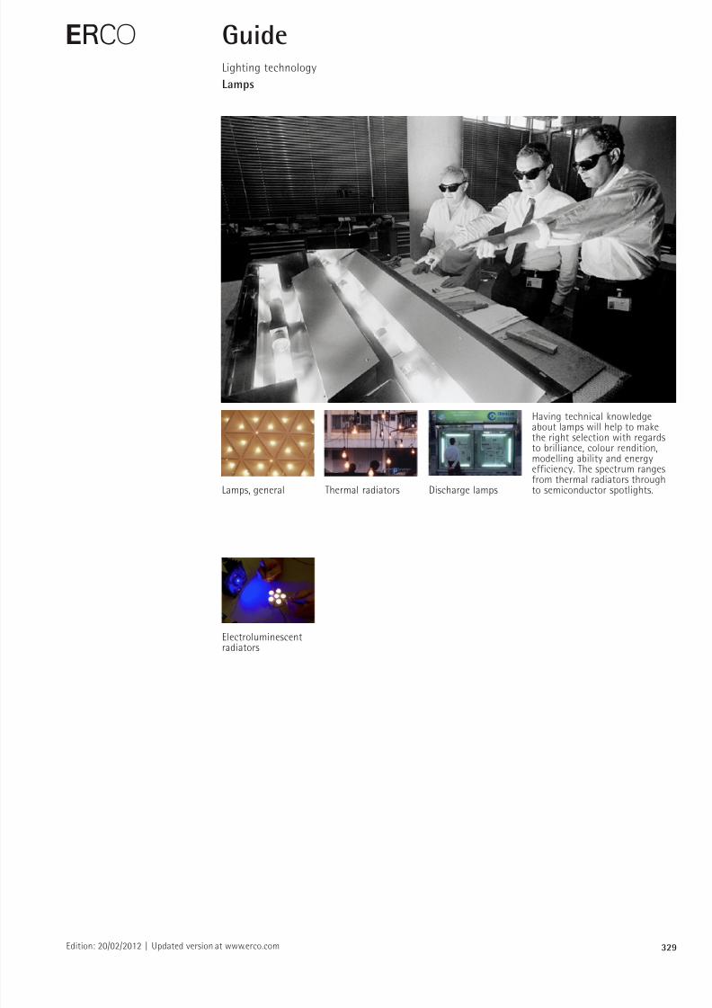
Having technical knowledgeabout lamps will help to makethe right selection with regardsto brilliance, colour rendition,modelling ability and energyefficiency. The spectrum rangesfrom thermal radiators throughto semiconductor spotlights.Lamps, general Discharge lampsThermal radiators
Electroluminescentradiators
8/13/2019 En Erco Guide 6 Lighting Technology
http://slidepdf.com/reader/full/en-erco-guide-6-lighting-technology 12/57
330Edition: 20/02/2012 | Updated version at www.erco.com
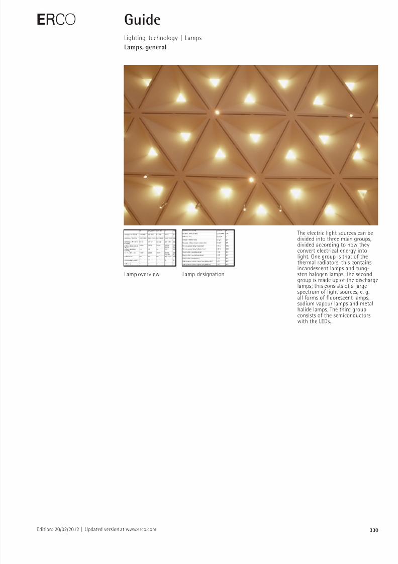
The electric light sources can bedivided into three main groups,divided according to how theyconvert electrical energy intolight. One group is that of thethermal radiators, this containsincandescent lamps and tung-sten halogen lamps. The secondgroup is made up of the dischargelamps; this consists of a largespectrum of light sources, e. g.
all forms of fluorescent lamps,sodium vapour lamps and metalhalide lamps. The third groupconsists of the semiconductorswith the LEDs.
E GuideLighting technology | Lamps
Lamps, general
Lamp overview Lamp designation
8/13/2019 En Erco Guide 6 Lighting Technology
http://slidepdf.com/reader/full/en-erco-guide-6-lighting-technology 13/57
331
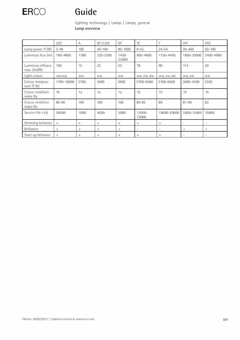
LED A QT (12V) QT TC T HIT HST
Lamp power P (W) 2-48 100 20-100 80-1000 9-55 24-54 20-400 50-100
Luminous flux (lm) 160-4800 1380 320-2200 1450-
22000
600-4800 1750-4450 1800-35000 2400-4900
Luminous efficacymax. (lm/W)
100 15 22 22 78 90 114 50
Light colour various ww ww ww ww, nw, dw ww, nw, dw ww, nw ww
Colour tempera-ture TF (K)
1700-10000 2700 3000 3000 2700-6500 2700-6500 3000-4200 2550
Colour renditionindex Ra
1b 1a 1a 1a 1b 1b 1b 1b
Colour renditionindex Ra
80-90 100 100 100 80-82 89 81-90 83
Service life t (h) 50000 1000 4000 2000 12000-13000
18000-20000 5000-15000 10000
Dimming behavior + + + + + + - -
Brilliance + + + + - - + +
Start up behavior + + + + + + - -
Edition: 20/02/2012 | Updated version at www.erco.com
E GuideLighting technology | Lamps | Lamps, general
Lamp overview
8/13/2019 En Erco Guide 6 Lighting Technology
http://slidepdf.com/reader/full/en-erco-guide-6-lighting-technology 14/57
332Edition: 20/02/2012 | Updated version at www.erco.com
E GuideLighting technology | Lamps | Lamps, general
Lamp designation
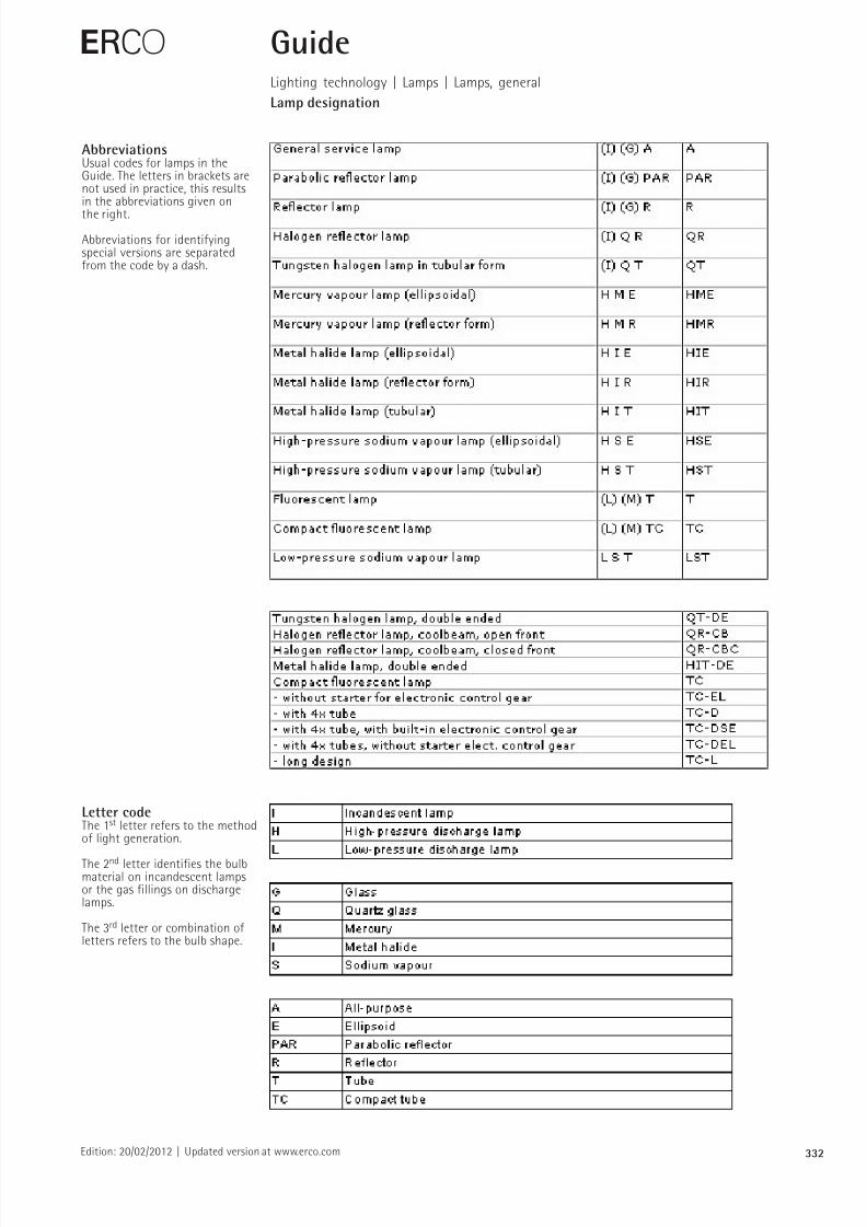
AbbreviationsUsual codes for lamps in theGuide. The letters in brackets arenot used in practice, this resultsin the abbreviations given on
the right.
Abbreviations for identifyingspecial versions are separatedfrom the code by a dash.
Letter codeThe 1st letter refers to the methodof light generation.
The 2nd letter identifies the bulbmaterial on incandescent lampsor the gas fillings on dischargelamps.
The 3rd letter or combination ofletters refers to the bulb shape.
8/13/2019 En Erco Guide 6 Lighting Technology
http://slidepdf.com/reader/full/en-erco-guide-6-lighting-technology 15/57
333Edition: 20/02/2012 | Updated version at www.erco.com
E GuideLighting technology | Lamps
Thermal radiators
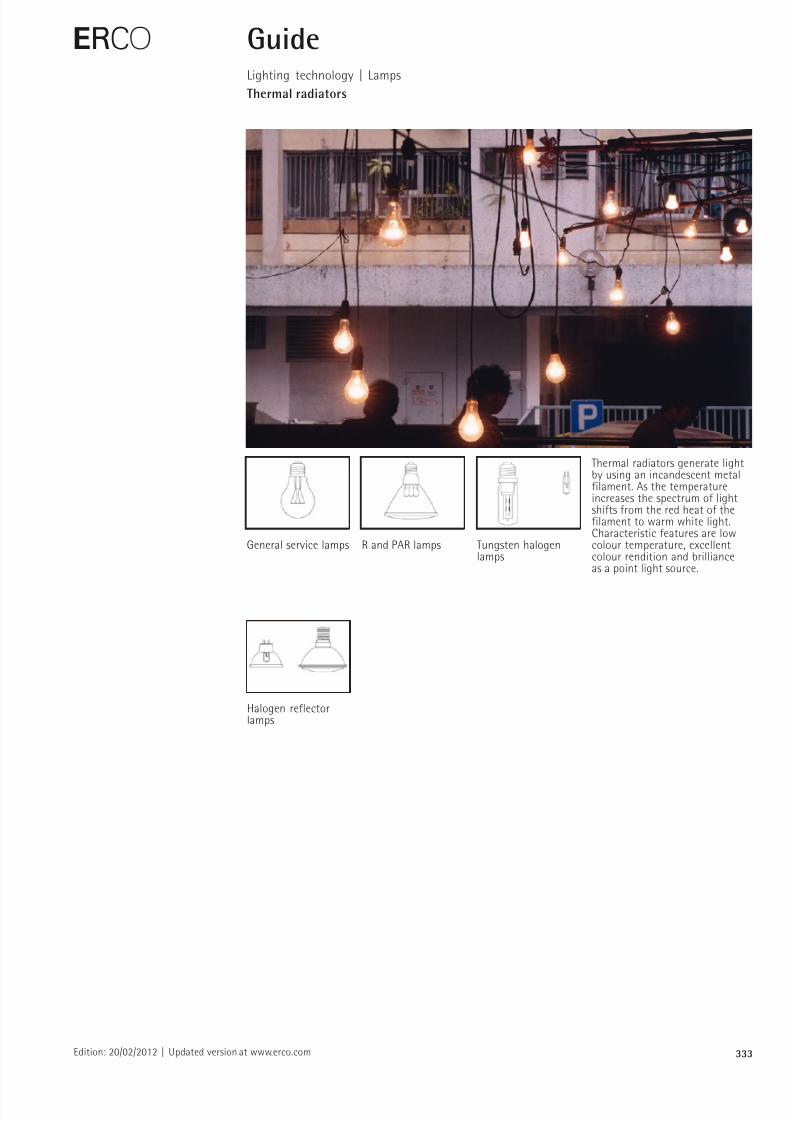
Thermal radiators generate lightby using an incandescent metalfilament. As the temperatureincreases the spectrum of lightshifts from the red heat of thefilament to warm white light.Characteristic features are lowcolour temperature, excellentcolour rendition and brillianceas a point light source.
General service lamps Tungsten halogenlamps
R and PAR lamps
Halogen reflectorlamps
8/13/2019 En Erco Guide 6 Lighting Technology
http://slidepdf.com/reader/full/en-erco-guide-6-lighting-technology 16/57
334
100
80
60
20
0
40
800
%
400 500 700600300
100
80
60
40
20
20(%)U/U
n
F(%) 2800 K
2700 K
2600 K
2500 K
2400 K
2300 K
2200 K
2100 K2000 K
100806040
0,500,400,30
0,26
0,34
0,42
x
y
dw
ww4000 k
5000 k
nw
Edition: 20/02/2012 | Updated version at www.erco.com
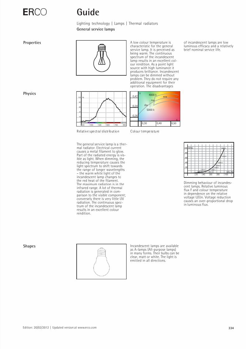
A low colour temperature ischaracteristic for the generalservice lamp. It is perceived asbeing warm. The continuousspectrum of the incandescent
lamp results in an excellent col-our rendition. As a point lightsource with high luminance itproduces brilliance. Incandescentlamps can be dimmed withoutproblem. They do not require anyadditional equipment for theiroperation. The disadvantages
Properties
E GuideLighting technology | Lamps | Thermal radiators
General service lamps
The general service lamp is a ther-mal radiator. Electrical currentcauses a metal filament to glow.Part of the radiated energy is vis-ible as light. When dimming, thereducing temperature causes thelight spectrum to shift towardsthe range of longer wavelengths– the warm white light of theincandescent lamp changes tothe red heat of the filament.
The maximum radiation is in theinfrared range. A lot of thermalradiation is generated in com-parison to the visible component;conversely there is very little UVradiation. The continuous spec-trum of the incandescent lampresults in an excellent colourrendition.
Physics
Relat ive spectral d istr ibution Colour temperature
Shapes Incandescent lamps are availableas A-lamps (All-purpose lamps)in many forms. Their bulbs can beclear, matt or white. The light isemitted in all directions.
Dimming behaviour of incandes-cent lamps. Relative luminousflux F and colour temperaturein dependence on the relativevoltage U/Un. Voltage reductioncauses an over-proportional dropin luminous flux.
of incandescent lamps are lowluminous efficacy and a relativelybrief nominal service life.
8/13/2019 En Erco Guide 6 Lighting Technology
http://slidepdf.com/reader/full/en-erco-guide-6-lighting-technology 17/57
335
100
80
60
40
20
20(%)U/U
n
F(%) 2800 K
2700 K
2600 K
2500 K
2400 K
2300 K
2200 K
2100 K2000 K
100806040
100
80
60
20
0
40
800
%
400 500 7006003000,500,400,30
0,26
0,34
0,42
x
y
dw
ww4000 k
5000 k
nw
Edition: 20/02/2012 | Updated version at www.erco.com
E GuideLighting technology | Lamps | Thermal radiators
R and PAR lamps
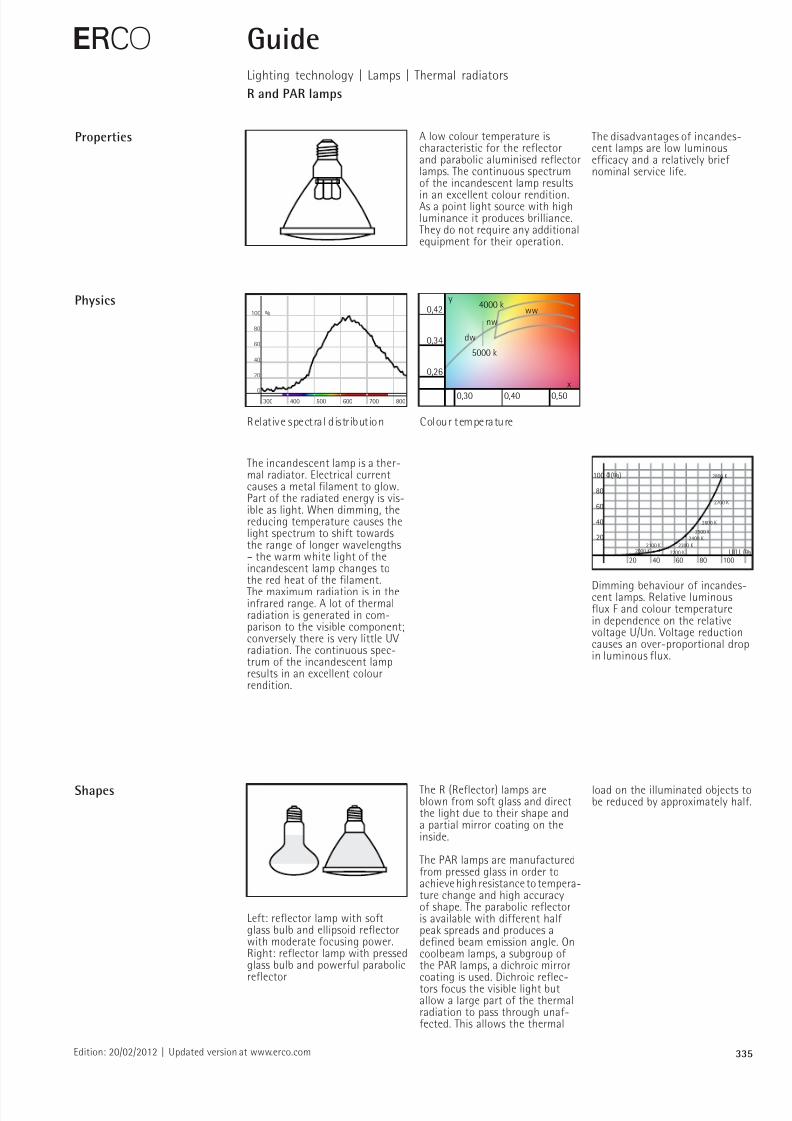
A low colour temperature ischaracteristic for the reflectorand parabolic aluminised reflectorlamps. The continuous spectrumof the incandescent lamp results
in an excellent colour rendition.As a point light source with highluminance it produces brilliance.They do not require any additionalequipment for their operation.
Properties
The incandescent lamp is a ther-mal radiator. Electrical currentcauses a metal filament to glow.Part of the radiated energy is vis-ible as light. When dimming, thereducing temperature causes thelight spectrum to shift towardsthe range of longer wavelengths– the warm white light of theincandescent lamp changes tothe red heat of the filament.
The maximum radiation is in theinfrared range. A lot of thermalradiation is generated in com-parison to the visible component;conversely there is very little UVradiation. The continuous spec-trum of the incandescent lampresults in an excellent colourrendition.
Physics
Relat ive spectral d istr ibution Colour temperature
Shapes The R (Reflector) lamps areblown from soft glass and directthe light due to their shape anda partial mirror coating on theinside.
The PAR lamps are manufacturedfrom pressed glass in order toachieve high resistance to tempera-ture change and high accuracyof shape. The parabolic reflectoris available with different halfpeak spreads and produces adefined beam emission angle. Oncoolbeam lamps, a subgroup ofthe PAR lamps, a dichroic mirror
coating is used. Dichroic reflec-tors focus the visible light butallow a large part of the thermalradiation to pass through unaf-fected. This allows the thermal
Dimming behaviour of incandes-cent lamps. Relative luminousflux F and colour temperaturein dependence on the relativevoltage U/Un. Voltage reductioncauses an over-proportional dropin luminous flux.
Left: reflector lamp with softglass bulb and ellipsoid reflectorwith moderate focusing power.Right: reflector lamp with pressedglass bulb and powerful parabolic
reflector
load on the illuminated objects tobe reduced by approximately half.
The disadvantages of incandes-cent lamps are low luminousefficacy and a relatively briefnominal service life.
8/13/2019 En Erco Guide 6 Lighting Technology
http://slidepdf.com/reader/full/en-erco-guide-6-lighting-technology 18/57
336
100
80
60
40
20
20(%)U/U
n
F(%) 2800 K
2700 K
2600 K
2500 K
2400 K
2300 K
2200 K
2100 K2000 K
100806040
100
80
60
20
0
40
800
%
400 500 7006003000,500,400,30
0,26
0,34
0,42
x
y
dw
ww4000 k
5000 k
nw
Edition: 20/02/2012 | Updated version at www.erco.com
E GuideLighting technology | Lamps | Thermal radiators
Tungsten halogen lamps
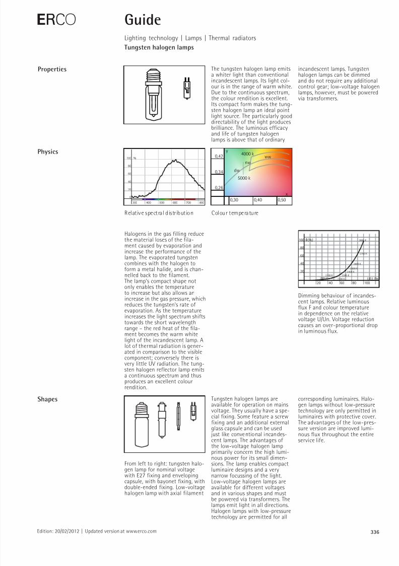
The tungsten halogen lamp emitsa whiter light than conventionalincandescent lamps. Its light col-our is in the range of warm white.Due to the continuous spectrum,
the colour rendition is excellent.Its compact form makes the tung-sten halogen lamp an ideal pointlight source. The particularly gooddirectability of the light producesbrilliance. The luminous efficacyand life of tungsten halogenlamps is above that of ordinary
Properties
Halogens in the gas filling reducethe material loses of the fila-ment caused by evaporation andincrease the performance of thelamp. The evaporated tungstencombines with the halogen toform a metal halide, and is chan-nelled back to the filament.The lamp‘s compact shape notonly enables the temperatureto increase but also allows an
increase in the gas pressure, whichreduces the tungsten‘s rate ofevaporation. As the temperatureincreases the light spectrum shiftstowards the short wavelengthrange – the red heat of the fila-ment becomes the warm whitelight of the incandescent lamp. Alot of thermal radiation is gener-ated in comparison to the visiblecomponent; conversely there isvery little UV radiation. The tung-sten halogen reflector lamp emitsa continuous spectrum and thusproduces an excellent colourrendition.
Physics
Relat ive spectral d istr ibution Colour temperature
Shapes Tungsten halogen lamps areavailable for operation on mainsvoltage. They usually have a spe-cial fixing. Some feature a screwfixing and an additional externalglass capsule and can be used just like conventional incandes-cent lamps. The advantages ofthe low-voltage halogen lampprimarily concern the high lumi-nous power for its small dimen-sions. The lamp enables compactluminaire designs and a verynarrow focussing of the light.Low-voltage halogen lamps areavailable for different voltages
and in various shapes and mustbe powered via transformers. Thelamps emit light in all directions.Halogen lamps with low-pressuretechnology are permitted for all
Dimming behaviour of incandes-cent lamps. Relative luminousflux F and colour temperaturein dependence on the relativevoltage U/Un. Voltage reductioncauses an over-proportional dropin luminous flux.
From left to right: tungsten halo-gen lamp for nominal voltagewith E27 fixing and envelopingcapsule, with bayonet fixing, withdouble-ended fixing. Low-voltage
halogen lamp with axial filament
corresponding luminaires. Halo-gen lamps without low-pressuretechnology are only permitted inluminaires with protective cover.The advantages of the low-pres-sure version are improved lumi-nous flux throughout the entireservice life.
incandescent lamps. Tungstenhalogen lamps can be dimmedand do not require any additionalcontrol gear; low-voltage halogenlamps, however, must be powered
via transformers.
8/13/2019 En Erco Guide 6 Lighting Technology
http://slidepdf.com/reader/full/en-erco-guide-6-lighting-technology 19/57
337
100
80
60
40
20
20(%)U/U
n
F(%) 2800 K
2700 K
2600 K
2500 K
2400 K
2300 K
2200 K
2100 K2000 K
100806040
100
80
60
20
0
40
800
%
400 500 7006003000,500,400,30
0,26
0,34
0,42
x
y
dw
ww4000 k
5000 k
nw
Edition: 20/02/2012 | Updated version at www.erco.com
E GuideLighting technology | Lamps | Thermal radiators
Halogen reflector lamps
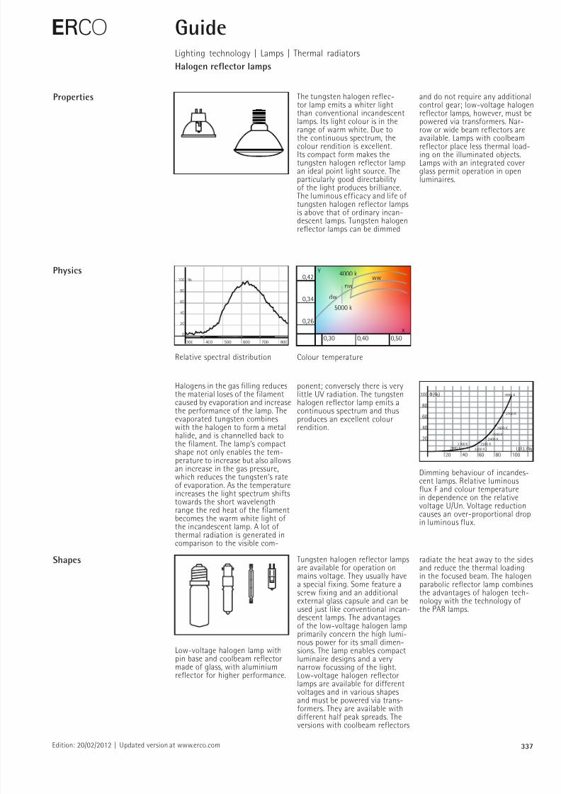
The tungsten halogen reflec-tor lamp emits a whiter lightthan conventional incandescentlamps. Its light colour is in therange of warm white. Due to
the continuous spectrum, thecolour rendition is excellent.Its compact form makes thetungsten halogen reflector lampan ideal point light source. Theparticularly good directabilityof the light produces brilliance.The luminous efficacy and life oftungsten halogen reflector lampsis above that of ordinary incan-descent lamps. Tungsten halogenreflector lamps can be dimmed
Properties
Halogens in the gas filling reducesthe material loses of the filamentcaused by evaporation and increasethe performance of the lamp. The
evaporated tungsten combineswith the halogen to form a metalhalide, and is channelled back tothe filament. The lamp‘s compactshape not only enables the tem-perature to increase but also allowsan increase in the gas pressure,which reduces the tungsten‘s rateof evaporation. As the temperatureincreases the light spectrum shiftstowards the short wavelengthrange the red heat of the filamentbecomes the warm white light ofthe incandescent lamp. A lot ofthermal radiation is generated incomparison to the visible com-
Physics
Relative spectral distribution Colour temperature
Shapes Tungsten halogen reflector lampsare available for operation onmains voltage. They usually havea special fixing. Some feature ascrew fixing and an additionalexternal glass capsule and can beused just like conventional incan-descent lamps. The advantagesof the low-voltage halogen lampprimarily concern the high lumi-nous power for its small dimen-sions. The lamp enables compactluminaire designs and a verynarrow focussing of the light.Low-voltage halogen reflectorlamps are available for different
voltages and in various shapesand must be powered via trans-formers. They are available withdifferent half peak spreads. Theversions with coolbeam reflectors
Dimming behaviour of incandes-cent lamps. Relative luminousflux F and colour temperaturein dependence on the relativevoltage U/Un. Voltage reductioncauses an over-proportional dropin luminous flux.
Low-voltage halogen lamp withpin base and coolbeam reflectormade of glass, with aluminiumreflector for higher performance.
radiate the heat away to the sidesand reduce the thermal loadingin the focused beam. The halogenparabolic reflector lamp combinesthe advantages of halogen tech-nology with the technology ofthe PAR lamps.
and do not require any additionalcontrol gear; low-voltage halogenreflector lamps, however, must bepowered via transformers. Nar-row or wide beam reflectors are
available. Lamps with coolbeamreflector place less thermal load-ing on the illuminated objects.Lamps with an integrated coverglass permit operation in openluminaires.
ponent; conversely there is verylittle UV radiation. The tungstenhalogen reflector lamp emits acontinuous spectrum and thus
produces an excellent colourrendition.
8/13/2019 En Erco Guide 6 Lighting Technology
http://slidepdf.com/reader/full/en-erco-guide-6-lighting-technology 20/57
338Edition: 20/02/2012 | Updated version at www.erco.com
E GuideLighting technology | Lamps
Discharge lamps
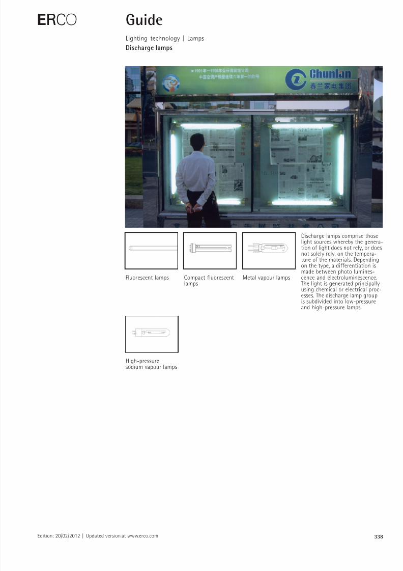
Discharge lamps comprise thoselight sources whereby the genera-tion of light does not rely, or doesnot solely rely, on the tempera-ture of the materials. Dependingon the type, a differentiation ismade between photo lumines-cence and electroluminescence.The light is generated principallyusing chemical or electrical proc-esses. The discharge lamp group
is subdivided into low-pressureand high-pressure lamps.
Fluorescent lamps Metal vapour lampsCompact fluorescentlamps
High-pressuresodium vapour lamps
8/13/2019 En Erco Guide 6 Lighting Technology
http://slidepdf.com/reader/full/en-erco-guide-6-lighting-technology 21/57
339
1 2 3
4 5
7
0,500,400,30
0,26
0,34
0,42
x
y
dw
ww4000 k
5000 k
nw
%100
80
60
20
0
40
800400 500 700600 nm300
Edition: 20/02/2012 | Updated version at www.erco.com
E GuideLighting technology | Lamps | Discharge lamps
Fluorescent lamps
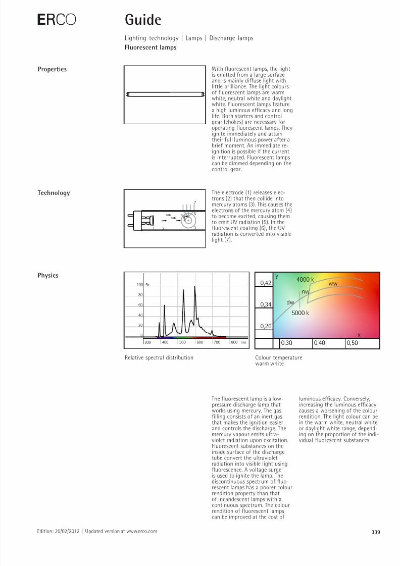
With fluorescent lamps, the lightis emitted from a large surfaceand is mainly diffuse light withlittle brilliance. The light coloursof fluorescent lamps are warm
white, neutral white and daylightwhite. Fluorescent lamps featurea high luminous efficacy and longlife. Both starters and controlgear (chokes) are necessary foroperating fluorescent lamps. Theyignite immediately and attaintheir full luminous power after abrief moment. An immediate re-ignition is possible if the currentis interrupted. Fluorescent lampscan be dimmed depending on thecontrol gear.
Properties
The electrode (1) releases elec-
trons (2) that then collide intomercury atoms (3). This causes theelectrons of the mercury atom (4)to become excited, causing themto emit UV radiation (5). In thefluorescent coating (6), the UVradiation is converted into visiblelight (7).
Technology
The fluorescent lamp is a low-pressure discharge lamp thatworks using mercury. The gasfilling consists of an inert gasthat makes the ignition easierand controls the discharge. Themercury vapour emits ultra-violet radiation upon excitation.Fluorescent substances on theinside surface of the dischargetube convert the ultravioletradiation into visible light usingfluorescence. A voltage surgeis used to ignite the lamp. Thediscontinuous spectrum of fluo-rescent lamps has a poorer colour
rendition property than thatof incandescent lamps with acontinuous spectrum. The colourrendition of fluorescent lampscan be improved at the cost of
Physics
Colour temperaturewarm white
Relative spectral distribution
luminous efficacy. Conversely,increasing the luminous efficacycauses a worsening of the colourrendition. The light colour can bein the warm white, neutral whiteor daylight white range, depend-ing on the proportion of the indi-vidual fluorescent substances.
8/13/2019 En Erco Guide 6 Lighting Technology
http://slidepdf.com/reader/full/en-erco-guide-6-lighting-technology 22/57
340
T26 18W, 36W, 58W
T16 14W, 35W, 54W
%100
80
60
20
0
40
800400 500 700600 nm300
%100
80
60
20
0
40
800400 500 700600 nm300 0,500,400,30
0,26
0,34
0,42
x
y
dw
ww4000 k
5000 k
nw
0,500,400,30
0,26
0,34
0,42
x
y
dw
ww4000 k
5000 k
nw
Edition: 20/02/2012 | Updated version at www.erco.com
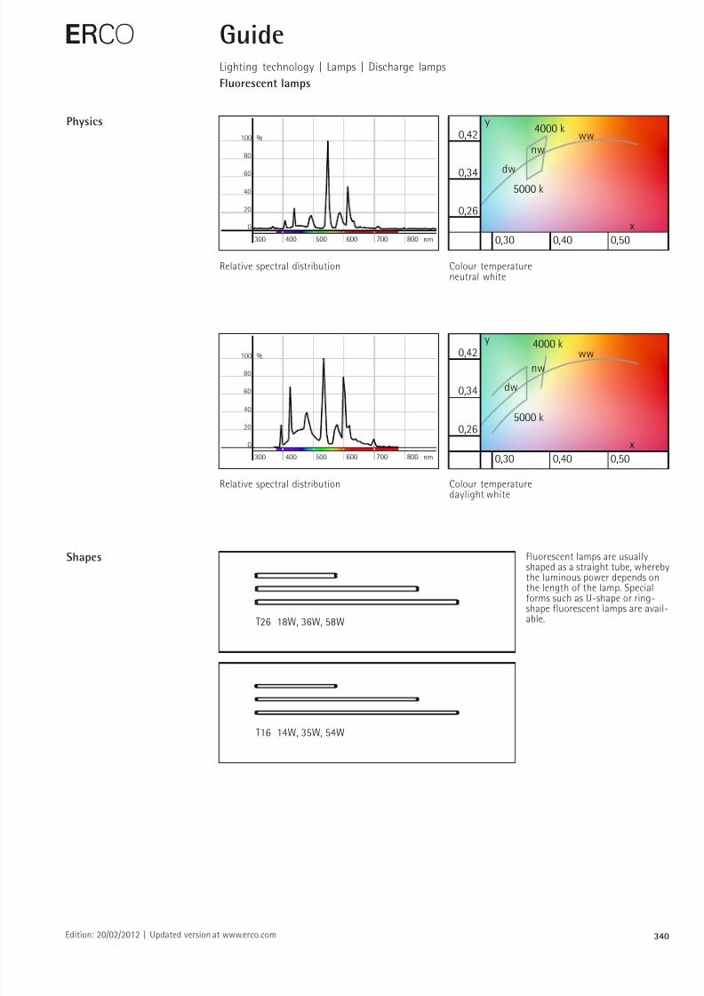
Shapes Fluorescent lamps are usuallyshaped as a straight tube, wherebythe luminous power depends onthe length of the lamp. Specialforms such as U-shape or ring-shape fluorescent lamps are avail-able.
Colour temperatureneutral white
Relative spectral distribution
Colour temperaturedaylight white
Relative spectral distribution
Physics
E GuideLighting technology | Lamps | Discharge lamps
Fluorescent lamps
8/13/2019 En Erco Guide 6 Lighting Technology
http://slidepdf.com/reader/full/en-erco-guide-6-lighting-technology 23/57
341Edition: 20/02/2012 | Updated version at www.erco.com
E GuideLighting technology | Lamps | Discharge lamps
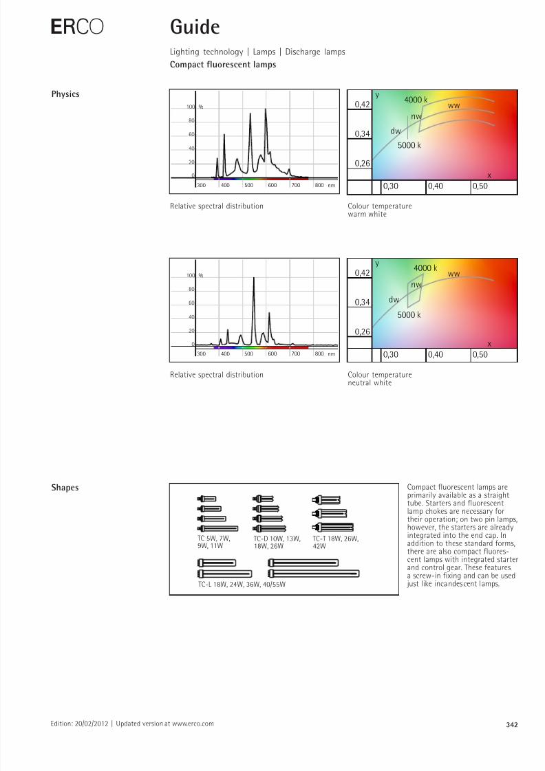
Compact fluorescent lamps
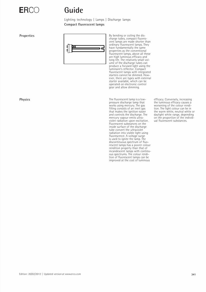
By bending or coiling the dis-charge tubes, compact fluores-cent lamps are made shorter thanordinary fluorescent lamps. Theyhave fundamentally the same
properties as the conventionalfluorescent lamps, above all theseare high luminous efficacy andlong life. The relatively small vol-ume of the discharge tubes canproduce a focused light using theluminaire‘s reflector. Compactfluorescent lamps with integratedstarters cannot be dimmed. How-ever, there are types with externalstarter available, which can beoperated on electronic controlgear and allow dimming.
Properties
Physics The fluorescent lamp is a low-
pressure discharge lamp thatworks using mercury. The gasfilling consists of an inert gasthat makes the ignition easierand controls the discharge. Themercury vapour emits ultra-violet radiation upon excitation.Fluorescent substances on theinside surface of the dischargetube convert the ultravioletradiation into visible light usingfluorescence. A voltage surgeis used to ignite the lamp. Thediscontinuous spectrum of fluo-rescent lamps has a poorer colourrendition property than that ofincandescent lamps with continu-ous spectrums. The colour rendi-tion of fluorescent lamps can beimproved at the cost of luminous
efficacy. Conversely, increasing
the luminous efficacy causes aworsening of the colour rendi-tion. The light colour can be inthe warm white, neutral white ordaylight white range, dependingon the proportion of the individ-ual fluorescent substances.
8/13/2019 En Erco Guide 6 Lighting Technology
http://slidepdf.com/reader/full/en-erco-guide-6-lighting-technology 24/57
342
TC-L 18W, 24W, 36W, 40/55W
TC 5W, 7W,9W, 11W TC-T 18W, 26W,42WTC-D 10W, 13W,18W, 26W
%100
80
60
20
0
40
800400 500 700600 nm300 0,500,400,30
0,26
0,34
0,42
x
y
dw
ww4000 k
5000 k
nw
0,500,400,30
0,26
0,34
0,42
x
y
dw
ww4000 k
5000 k
nw
%100
80
60
20
0
40
800400 500 700600 nm300
Edition: 20/02/2012 | Updated version at www.erco.com
Shapes Compact fluorescent lamps areprimarily available as a straighttube. Starters and fluorescentlamp chokes are necessary fortheir operation; on two pin lamps,however, the starters are alreadyintegrated into the end cap. Inaddition to these standard forms,there are also compact fluores-cent lamps with integrated starterand control gear. These featuresa screw-in fixing and can be used just like incandescent lamps.
E GuideLighting technology | Lamps | Discharge lamps
Compact fluorescent lamps
Colour temperatureneutral white
Relative spectral distribution
Physics
Colour temperaturewarm white
Relative spectral distribution
8/13/2019 En Erco Guide 6 Lighting Technology
http://slidepdf.com/reader/full/en-erco-guide-6-lighting-technology 25/57
343
%100
80
60
20
0
40
800400 500 700600 nm300
%100
80
60
20
0
40
800400 500 700600 nm300
0,500,400,30
0,26
0,34
0,42
x
y
dw
ww4000 k
5000 k
nw
0,500,400,30
0,26
0,34
0,42
x
y
dw
ww4000 k
5000 k
nw
Edition: 20/02/2012 | Updated version at www.erco.com
E GuideLighting technology | Lamps | Discharge lamps
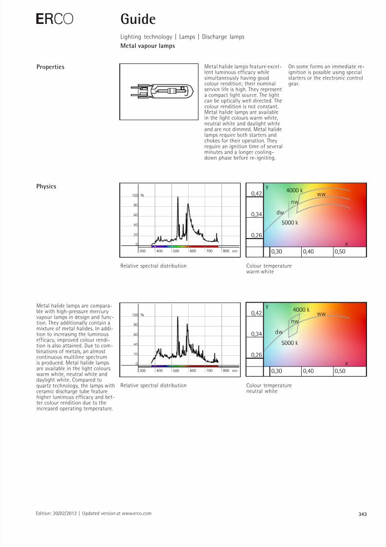
Metal vapour lamps
Metal halide lamps feature excel-lent luminous efficacy whilesimultaneously having goodcolour rendition; their nominalservice life is high. They represent
a compact light source. The lightcan be optically well directed. Thecolour rendition is not constant.Metal halide lamps are availablein the light colours warm white,neutral white and daylight whiteand are not dimmed. Metal halidelamps require both starters andchokes for their operation. Theyrequire an ignition time of severalminutes and a longer cooling-down phase before re-igniting.
Properties On some forms an immediate re-ignition is possible using specialstarters or the electronic controlgear.
Metal halide lamps are compara-ble with high-pressure mercuryvapour lamps in design and func-tion. They additionally contain amixture of metal halides. In addi-tion to increasing the luminousefficacy, improved colour rendi-tion is also attained. Due to com-binations of metals, an almostcontinuous multiline spectrumis produced. Metal halide lampsare available in the light colourswarm white, neutral white anddaylight white. Compared toquartz technology, the lamps withceramic discharge tube featurehigher luminous efficacy and bet-ter colour rendition due to theincreased operating temperature.
Physics
Colour temperaturewarm white
Relative spectral distribution
Colour temperatureneutral white
Relative spectral distribution
8/13/2019 En Erco Guide 6 Lighting Technology
http://slidepdf.com/reader/full/en-erco-guide-6-lighting-technology 26/57
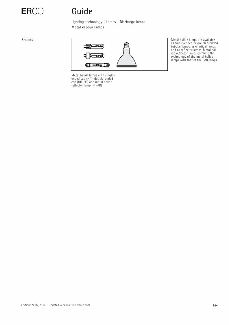
344Edition: 20/02/2012 | Updated version at www.erco.com
Shapes Metal halide lamps are availableas single-ended or doubled-endedtubular lamps, as elliptical lampsand as reflector lamps. Metal hal-ide reflector lamps combine the
technology of the metal halidelamps with that of the PAR lamps.
E GuideLighting technology | Lamps | Discharge lamps
Metal vapour lamps
Metal halide lamps with single-ended cap (HIT), double-endedcap (HIT-DE) and metal halidereflector lamp (HIPAR)
8/13/2019 En Erco Guide 6 Lighting Technology
http://slidepdf.com/reader/full/en-erco-guide-6-lighting-technology 27/57
345
%100
80
60
20
0
40
800400 500 700600 nm300 0,500,400,30
0,26
0,34
0,42
x
y
dw
ww4000 k
5000 k
nw
Edition: 20/02/2012 | Updated version at www.erco.com
E GuideLighting technology | Lamps | Discharge lamps
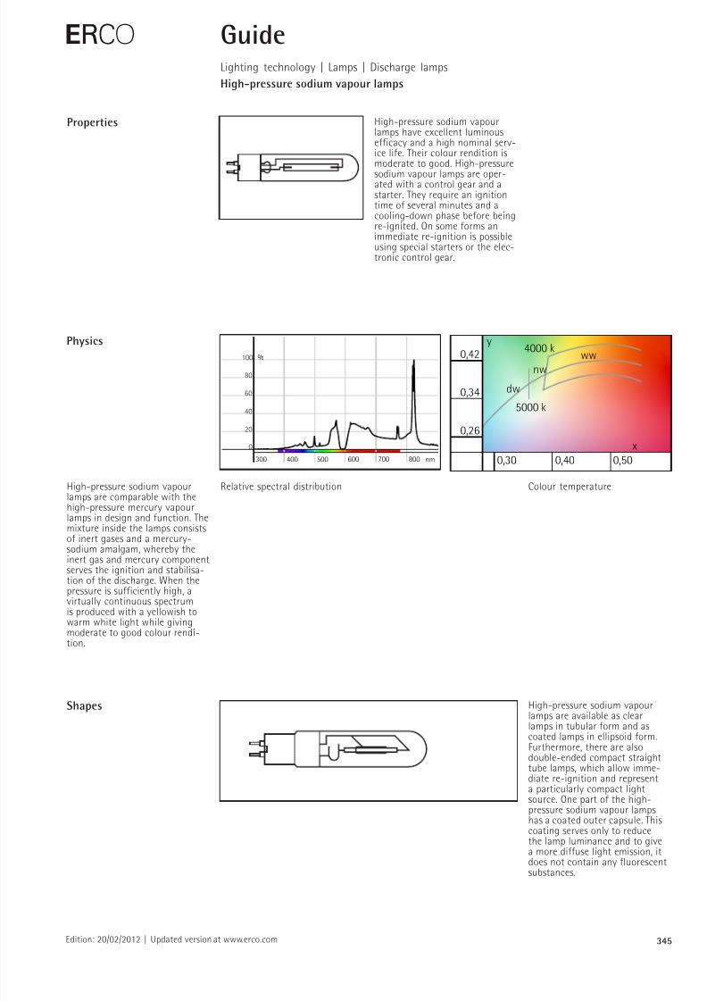
High-pressure sodium vapour lamps
High-pressure sodium vapourlamps have excellent luminousefficacy and a high nominal serv-ice life. Their colour rendition ismoderate to good. High-pressure
sodium vapour lamps are oper-ated with a control gear and astarter. They require an ignitiontime of several minutes and acooling-down phase before beingre-ignited. On some forms animmediate re-ignition is possibleusing special starters or the elec-tronic control gear.
Properties
High-pressure sodium vapourlamps are comparable with thehigh-pressure mercury vapourlamps in design and function. The
mixture inside the lamps consistsof inert gases and a mercury-sodium amalgam, whereby theinert gas and mercury componentserves the ignition and stabilisa-tion of the discharge. When thepressure is sufficiently high, avirtually continuous spectrumis produced with a yellowish towarm white light while givingmoderate to good colour rendi-tion.
Physics
Colour temperatureRelative spectral distribution
Shapes High-pressure sodium vapourlamps are available as clearlamps in tubular form and ascoated lamps in ellipsoid form.Furthermore, there are alsodouble-ended compact straighttube lamps, which allow imme-diate re-ignition and representa particularly compact lightsource. One part of the high-pressure sodium vapour lampshas a coated outer capsule. Thiscoating serves only to reducethe lamp luminance and to givea more diffuse light emission, itdoes not contain any fluorescent
substances.
8/13/2019 En Erco Guide 6 Lighting Technology
http://slidepdf.com/reader/full/en-erco-guide-6-lighting-technology 28/57
346Edition: 20/02/2012 | Updated version at www.erco.com
E GuideLighting technology | Lamps
Electroluminescent radiators
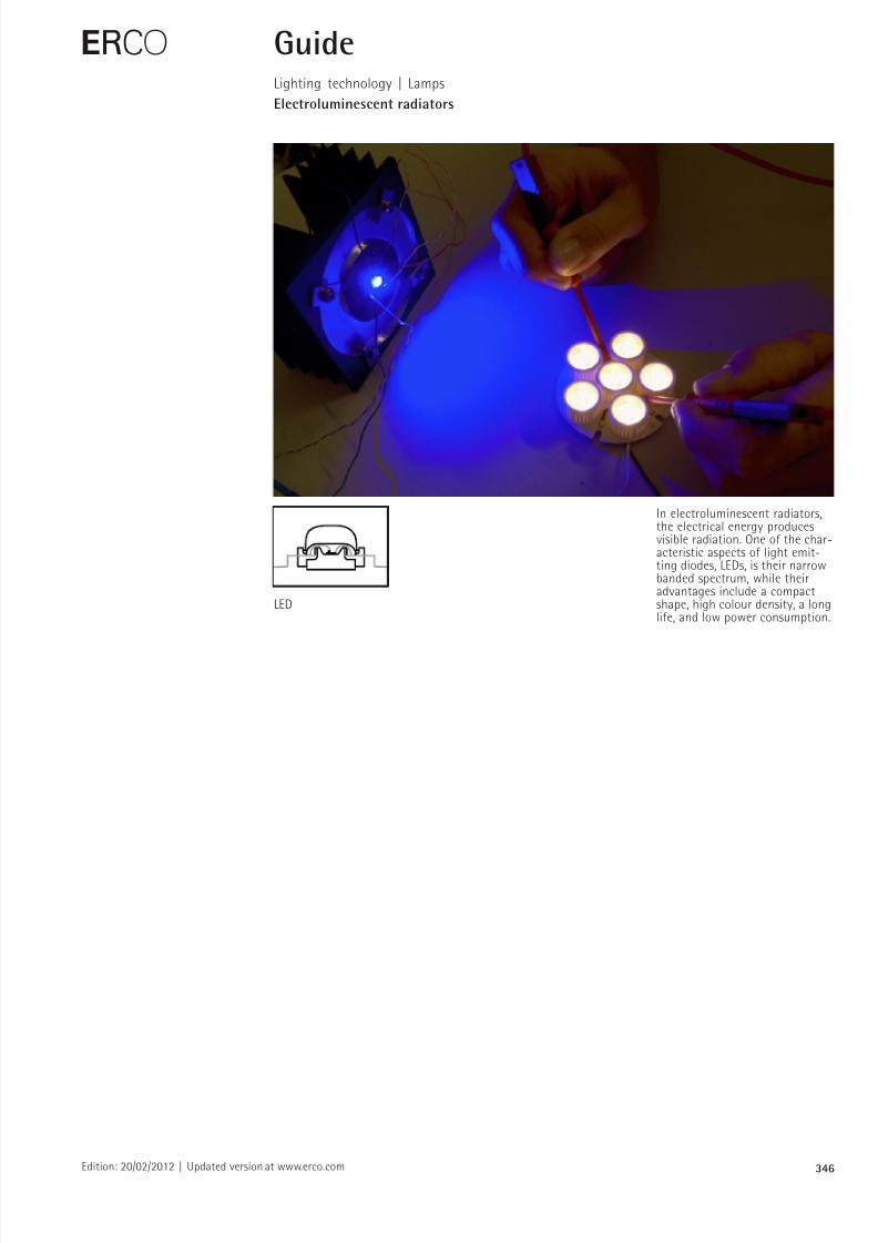
In electroluminescent radiators,the electrical energy producesvisible radiation. One of the char-acteristic aspects of light emit-ting diodes, LEDs, is their narrowbanded spectrum, while theiradvantages include a compactshape, high colour density, a longlife, and low power consumption.
LED
8/13/2019 En Erco Guide 6 Lighting Technology
http://slidepdf.com/reader/full/en-erco-guide-6-lighting-technology 29/57
347
Anode
Substrate
n-layer
Active region
p-layer
Cathode
%100
80
60
20
0
40
800400 500 700600 nm300
Edition: 20/02/2012 | Updated version at www.erco.com
E GuideLighting technology | Lamps | Electroluminescent radiators
LED
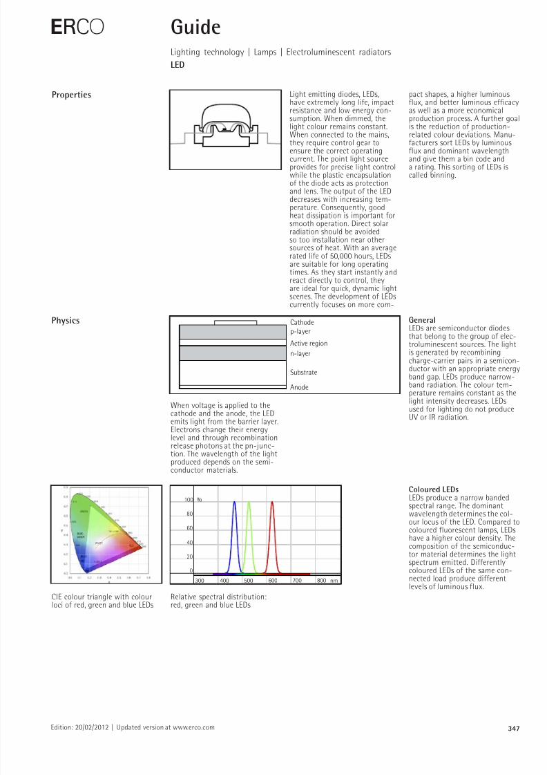
Light emitting diodes, LEDs,have extremely long life, impactresistance and low energy con-sumption. When dimmed, thelight colour remains constant.
When connected to the mains,they require control gear toensure the correct operatingcurrent. The point light sourceprovides for precise light controlwhile the plastic encapsulationof the diode acts as protectionand lens. The output of the LEDdecreases with increasing tem-perature. Consequently, goodheat dissipation is important forsmooth operation. Direct solarradiation should be avoidedso too installation near othersources of heat. With an averagerated life of 50,000 hours, LEDsare suitable for long operating
times. As they start instantly andreact directly to control, theyare ideal for quick, dynamic lightscenes. The development of LEDscurrently focuses on more com-
Properties pact shapes, a higher luminousflux, and better luminous efficacyas well as a more economicalproduction process. A further goalis the reduction of production-
related colour deviations. Manu-facturers sort LEDs by luminousflux and dominant wavelengthand give them a bin code anda rating. This sorting of LEDs iscalled binning.
GeneralLEDs are semiconductor diodesthat belong to the group of elec-troluminescent sources. The lightis generated by recombiningcharge-carrier pairs in a semicon-ductor with an appropriate energyband gap. LEDs produce narrow-band radiation. The colour tem-perature remains constant as thelight intensity decreases. LEDs
used for lighting do not produceUV or IR radiation.
Physics
When voltage is applied to thecathode and the anode, the LEDemits light from the barrier layer.Electrons change their energylevel and through recombinationrelease photons at the pn-junc-tion. The wavelength of the lightproduced depends on the semi-conductor materials.
Coloured LEDsLEDs produce a narrow bandedspectral range. The dominantwavelength determines the col-our locus of the LED. Compared tocoloured fluorescent lamps, LEDshave a higher colour density. Thecomposition of the semiconduc-tor material determines the lightspectrum emitted. Differentlycoloured LEDs of the same con-nected load produce differentlevels of luminous flux.
Relative spectral distribution:red, green and blue LEDs
CIE colour triangle with colourloci of red, green and blue LEDs
8/13/2019 En Erco Guide 6 Lighting Technology
http://slidepdf.com/reader/full/en-erco-guide-6-lighting-technology 30/57
348
%100
80
60
20
0
40
800400 500 700600 nm300
%100
80
60
20
0
40
800400 500 700600 nm300
Edition: 20/02/2012 | Updated version at www.erco.com
Shapes
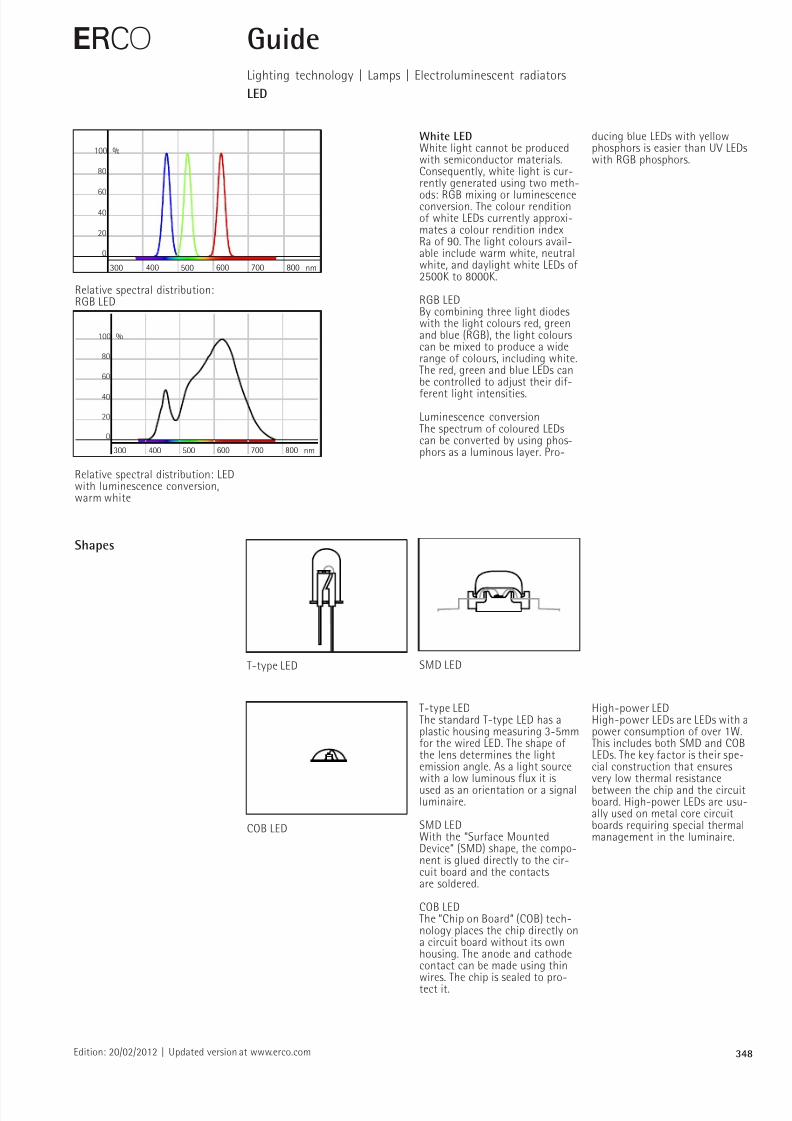
T-type LEDThe standard T-type LED has aplastic housing measuring 3-5mmfor the wired LED. The shape ofthe lens determines the lightemission angle. As a light sourcewith a low luminous flux it isused as an orientation or a signalluminaire.
SMD LEDWith the “Surface MountedDevice“ (SMD) shape, the compo-nent is glued directly to the cir-cuit board and the contactsare soldered.
COB LEDThe “Chip on Board“ (COB) tech-nology places the chip directly ona circuit board without its ownhousing. The anode and cathodecontact can be made using thin
wires. The chip is sealed to pro-tect it.
White LEDWhite light cannot be producedwith semiconductor materials.Consequently, white light is cur-rently generated using two meth-
ods: RGB mixing or luminescenceconversion. The colour renditionof white LEDs currently approxi-mates a colour rendition indexRa of 90. The light colours avail-able include warm white, neutralwhite, and daylight white LEDs of2500K to 8000K.
RGB LEDBy combining three light diodeswith the light colours red, greenand blue (RGB), the light colourscan be mixed to produce a widerange of colours, including white.The red, green and blue LEDs canbe controlled to adjust their dif-
ferent light intensities.
Luminescence conversionThe spectrum of coloured LEDscan be converted by using phos-phors as a luminous layer. Pro-
Relative spectral distribution: LEDwith luminescence conversion,warm white
Relative spectral distribution:RGB LED
E GuideLighting technology | Lamps | Electroluminescent radiators
LED
T-type LED SMD LED
COB LED
ducing blue LEDs with yellowphosphors is easier than UV LEDswith RGB phosphors.
High-power LEDHigh-power LEDs are LEDs with apower consumption of over 1W.This includes both SMD and COBLEDs. The key factor is their spe-cial construction that ensuresvery low thermal resistancebetween the chip and the circuitboard. High-power LEDs are usu-ally used on metal core circuitboards requiring special thermalmanagement in the luminaire.
8/13/2019 En Erco Guide 6 Lighting Technology
http://slidepdf.com/reader/full/en-erco-guide-6-lighting-technology 31/57
349Edition: 03/01/2010 | Updated version at www.erco.com
E GuideLighting technology
Luminaire technology
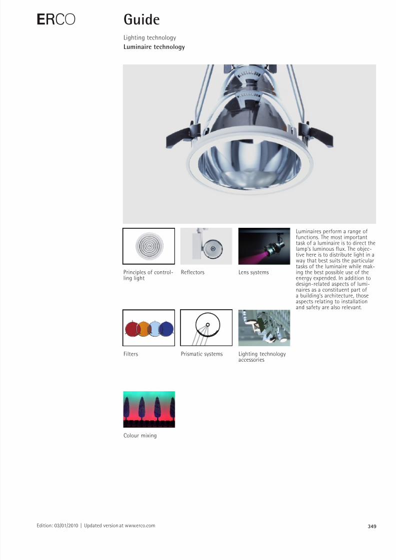
Luminaires perform a range offunctions. The most importanttask of a luminaire is to direct thelamp‘s luminous flux. The objec-tive here is to distribute light in away that best suits the particulartasks of the luminaire while mak-ing the best possible use of theenergy expended. In addition todesign-related aspects of lumi-naires as a constituent part of
a building‘s architecture, thoseaspects relating to installationand safety are also relevant.
Principles of control-ling light
Lens systemsReflectors
Filters Lighting technologyaccessories
Prismatic systems
Colour mixing
8/13/2019 En Erco Guide 6 Lighting Technology
http://slidepdf.com/reader/full/en-erco-guide-6-lighting-technology 32/57
350Edition: 03/01/2010 | Updated version at www.erco.com
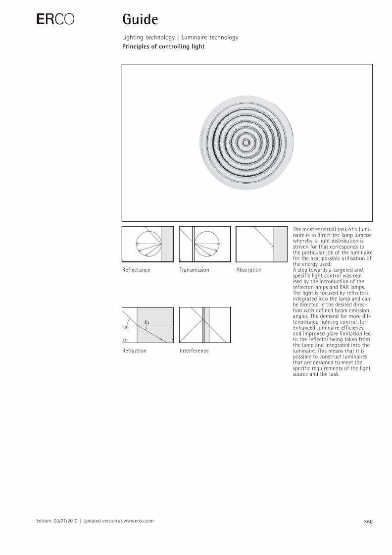
The most essential task of a lumi-naire is to direct the lamp lumens;whereby, a light distribution isstriven for that corresponds tothe particular job of the luminairefor the best possible utilisation ofthe energy used.A step towards a targeted andspecific light control was real-ised by the introduction of thereflector lamps and PAR lamps.
The light is focused by reflectorsintegrated into the lamp and canbe directed in the desired direc-tion with defined beam emissionangles. The demand for more dif-ferentiated lighting control, forenhanced luminaire efficiencyand improved glare limitation ledto the reflector being taken fromthe lamp and integrated into theluminaire. This means that it ispossible to construct luminairesthat are designed to meet thespecific requirements of the lightsource and the task.
E GuideLighting technology | Luminaire technology
Principles of controlling light
Reflectance Transmission Absorption
Refraction Interference
8/13/2019 En Erco Guide 6 Lighting Technology
http://slidepdf.com/reader/full/en-erco-guide-6-lighting-technology 33/57
351Edition: 03/01/2010 | Updated version at www.erco.com
E GuideLighting technology | Luminaire technology | Principles of controlling light
Reflectance
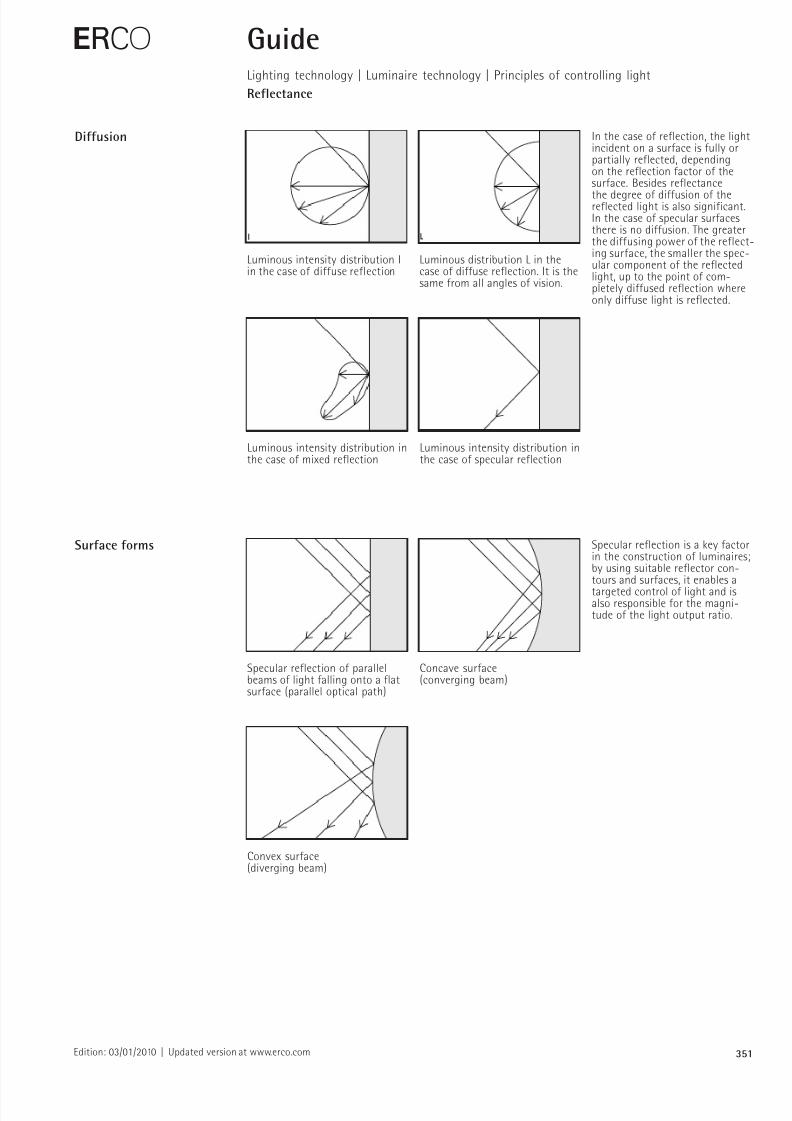
In the case of reflection, the lightincident on a surface is fully orpartially reflected, dependingon the reflection factor of thesurface. Besides reflectance
the degree of diffusion of thereflected light is also significant.In the case of specular surfacesthere is no diffusion. The greaterthe diffusing power of the reflect-ing surface, the smaller the spec-ular component of the reflectedlight, up to the point of com-pletely diffused reflection whereonly diffuse light is reflected.
Luminous intensity distribution Iin the case of diffuse reflection
Luminous distribution L in thecase of diffuse reflection. It is thesame from all angles of vision.
Luminous intensity distribution inthe case of mixed reflection
Luminous intensity distribution inthe case of specular reflection
Diffusion
Specular reflection is a key factorin the construction of luminaires;by using suitable reflector con-tours and surfaces, it enables a
targeted control of light and isalso responsible for the magni-tude of the light output ratio.
Surface forms
Specular reflection of parallelbeams of light falling onto a flatsurface (parallel optical path)
Concave surface(converging beam)
Convex surface(diverging beam)
8/13/2019 En Erco Guide 6 Lighting Technology
http://slidepdf.com/reader/full/en-erco-guide-6-lighting-technology 34/57
352
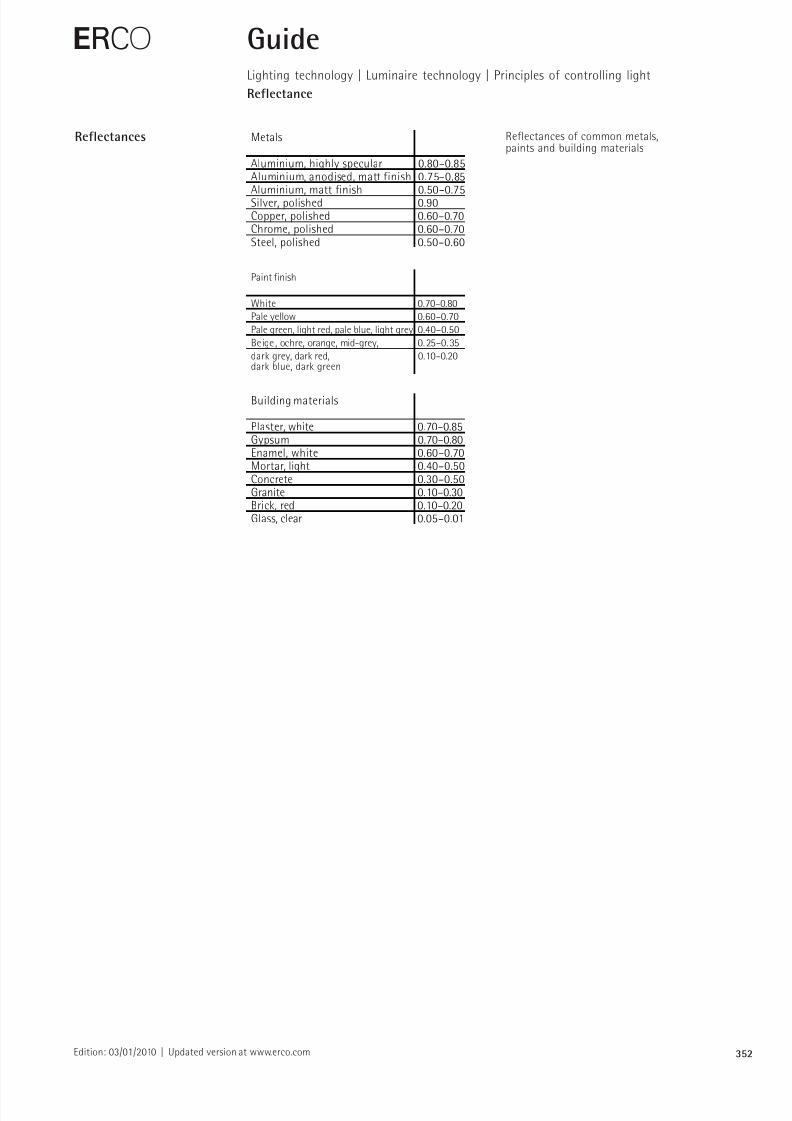
Paint finish
White 0.70–0.80
Pale yellow 0.60–0.70
0.40–0.50
Be ige , ochre, orange, mid-grey, 0.25–0.35
dark grey, dark red, 0.10–0.20dark blue, dark green
Pale green, light red, pale blue, light grey
Metals
Aluminium, highly specular 0.80–0.85Aluminium, anodised, matt finish 0.75–0.85Aluminium, matt finish 0.50–0.75Silver, polished 0.90Copper, polished 0.60–0.70Chrome, polished 0.60–0.70Steel, polished 0.50–0.60
Building materials
Plaster, white 0.70–0.85Gypsum 0.70–0.80Enamel, white 0.60–0.70Mortar, light 0.40–0.50Concrete 0.30–0.50Granite 0.10–0.30Brick, red 0.10–0.20Glass, clear 0.05–0.01
Edition: 03/01/2010 | Updated version at www.erco.com
E GuideLighting technology | Luminaire technology | Principles of controlling light
Reflectance
Reflectances of common metals,paints and building materials
Reflectances
8/13/2019 En Erco Guide 6 Lighting Technology
http://slidepdf.com/reader/full/en-erco-guide-6-lighting-technology 35/57
353Edition: 03/01/2010 | Updated version at www.erco.com
E GuideLighting technology | Luminaire technology | Principles of controlling light
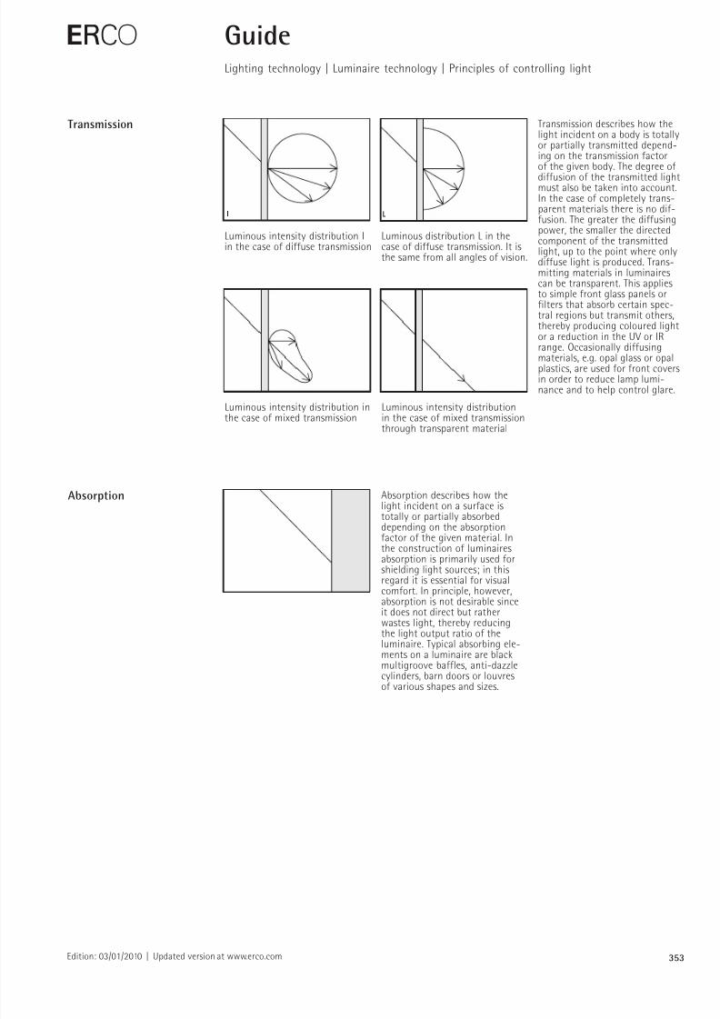
Transmission describes how thelight incident on a body is totallyor partially transmitted depend-ing on the transmission factorof the given body. The degree of
diffusion of the transmitted lightmust also be taken into account.In the case of completely trans-parent materials there is no dif-fusion. The greater the diffusingpower, the smaller the directedcomponent of the transmittedlight, up to the point where onlydiffuse light is produced. Trans-mitting materials in luminairescan be transparent. This appliesto simple front glass panels orfilters that absorb certain spec-tral regions but transmit others,thereby producing coloured lightor a reduction in the UV or IRrange. Occasionally diffusing
materials, e.g. opal glass or opalplastics, are used for front coversin order to reduce lamp lumi-nance and to help control glare.
Luminous intensity distribution Iin the case of diffuse transmission
Luminous distribution L in thecase of diffuse transmission. It isthe same from all angles of vision.
Luminous intensity distribution inthe case of mixed transmission
Luminous intensity distributionin the case of mixed transmissionthrough transparent material
Transmission
Absorption describes how thelight incident on a surface istotally or partially absorbeddepending on the absorption
factor of the given material. Inthe construction of luminairesabsorption is primarily used forshielding light sources; in thisregard it is essential for visualcomfort. In principle, however,absorption is not desirable sinceit does not direct but ratherwastes light, thereby reducingthe light output ratio of theluminaire. Typical absorbing ele-ments on a luminaire are blackmultigroove baffles, anti-dazzlecylinders, barn doors or louvresof various shapes and sizes.
Absorption
8/13/2019 En Erco Guide 6 Lighting Technology
http://slidepdf.com/reader/full/en-erco-guide-6-lighting-technology 36/57
354
n1 n2
1 3
2 3
2 2
2
2
2
2
2
2
2
2
2
2
2
n1n2
G 3
2
2
2
Edition: 03/01/2010 | Updated version at www.erco.com
E GuideLighting technology | Luminaire technology | Principles of controlling light
Refraction
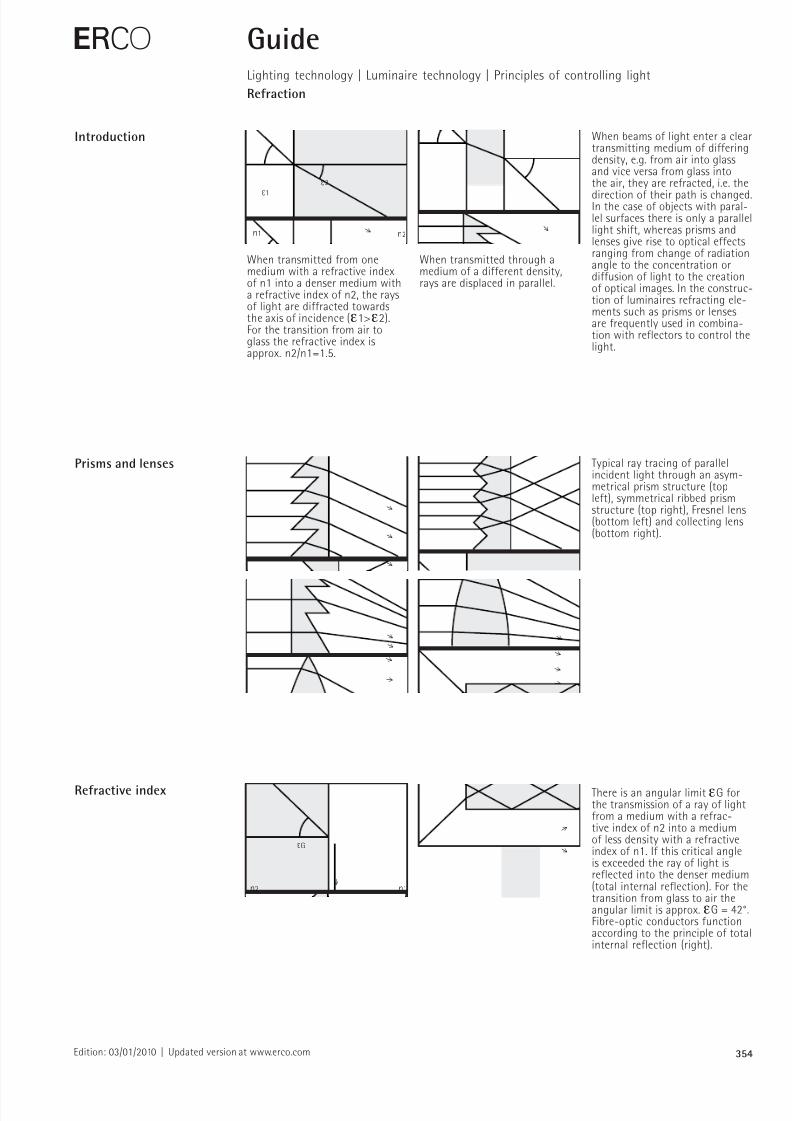
When beams of light enter a cleartransmitting medium of differingdensity, e.g. from air into glassand vice versa from glass intothe air, they are refracted, i.e. the
direction of their path is changed.In the case of objects with paral-lel surfaces there is only a parallellight shift, whereas prisms andlenses give rise to optical effectsranging from change of radiationangle to the concentration ordiffusion of light to the creationof optical images. In the construc-tion of luminaires refracting ele-ments such as prisms or lensesare frequently used in combina-tion with reflectors to control thelight.
When transmitted from onemedium with a refractive indexof n1 into a denser medium witha refractive index of n2, the raysof light are diffracted towardsthe axis of incidence (ε1>ε2).For the transition from air toglass the refractive index isapprox. n2/n1=1.5.
When transmitted through amedium of a different density,rays are displaced in parallel.
Introduction
Prisms and lenses Typical ray tracing of parallelincident light through an asym-metrical prism structure (topleft), symmetrical ribbed prismstructure (top right), Fresnel lens(bottom left) and collecting lens(bottom right).
Refractive index There is an angular limit εG forthe transmission of a ray of lightfrom a medium with a refrac-tive index of n2 into a mediumof less density with a refractiveindex of n1. If this critical angleis exceeded the ray of light isreflected into the denser medium(total internal reflection). For thetransition from glass to air theangular limit is approx. εG = 42°.Fibre-optic conductors functionaccording to the principle of totalinternal reflection (right).
8/13/2019 En Erco Guide 6 Lighting Technology
http://slidepdf.com/reader/full/en-erco-guide-6-lighting-technology 37/57
355
1 1
Edition: 03/01/2010 | Updated version at www.erco.com
E GuideLighting technology | Luminaire technology | Principles of controlling light
Interference
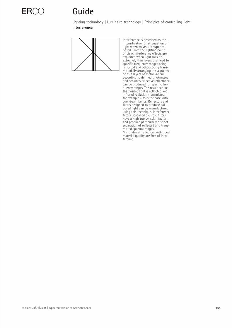
Interference is described as theintensification or attenuation oflight when waves are superim-posed. From the lighting pointof view, interference effects are
exploited when light falls onextremely thin layers that lead tospecific frequency ranges beingreflected and others being trans-mitted. By arranging the sequenceof thin layers of metal vapouraccording to defined thicknessesand densities, selective reflectancecan be produced for specific fre-quency ranges. The result can bethat visible light is reflected andinfrared radiation transmitted,for example – as is the case withcool-beam lamps. Reflectors andfilters designed to produce col-oured light can be manufacturedusing this technique. Interference
filters, so-called dichroic filters,have a high transmission factorand produce particularly distinctseparation of reflected and trans-mitted spectral ranges.Mirror-finish reflectors with goodmaterial quality are free of inter-ference.
8/13/2019 En Erco Guide 6 Lighting Technology
http://slidepdf.com/reader/full/en-erco-guide-6-lighting-technology 38/57
356Edition: 03/01/2010 | Updated version at www.erco.com
E
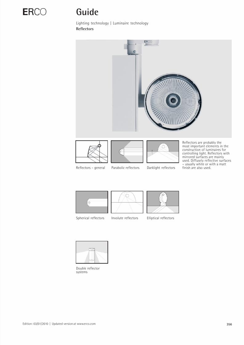
Reflectors are probably themost important elements in theconstruction of luminaires forcontrolling light. Reflectors withmirrored surfaces are mainlyused. Diffusely reflective surfaces– usually white or with a mattfinish are also used.Reflectors – general Darklight reflectorsParabolic reflectors
Spherical reflectors Elliptical reflectorsInvolute reflectors
Double reflectorsystems
GuideLighting technology | Luminaire technology
Reflectors
8/13/2019 En Erco Guide 6 Lighting Technology
http://slidepdf.com/reader/full/en-erco-guide-6-lighting-technology 39/57
357Edition: 03/01/2010 | Updated version at www.erco.com
E GuideLighting technology | Luminaire technology | Reflectors
Reflectors – general
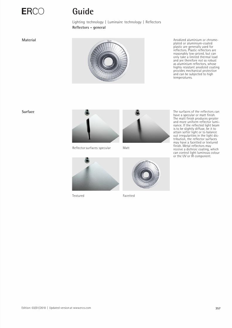
Anodized aluminium or chrome-plated or aluminium-coatedplastic are generally used forreflectors. Plastic reflectors arereasonably low-priced, but can
only take a limited thermal loadand are therefore not so robustas aluminium reflectors, whosehighly resistant anodized coatingprovides mechanical protectionand can be subjected to hightemperatures.
Material
Surface
Reflector surfaces: specular Matt
Textured Facetted
The surfaces of the reflectors can
have a specular or matt finish.The matt finish produces greaterand more uniform reflector lumi-nance. If the reflected light beamis to be slightly diffuse, be it toattain softer light or to balanceout irregularities in the light dis-tribution, the reflector surfacesmay have a facetted or texturedfinish. Metal reflectors mayreceive a dichroic coating, whichcan control light luminous colouror the UV or IR component.
8/13/2019 En Erco Guide 6 Lighting Technology
http://slidepdf.com/reader/full/en-erco-guide-6-lighting-technology 40/57
358
1
2
3 4
1
2
3 4
3
2
Edition: 03/01/2010 | Updated version at www.erco.com
E
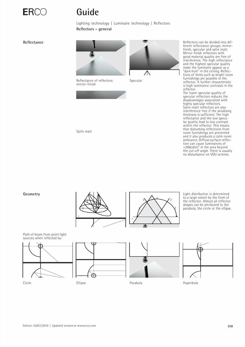
Reflectors can be divided into dif-ferent reflectance groups: mirror-finish, specular and satin matt.Mirror-finish reflectors withgood material quality are free of
interference. The high reflectanceand the highest specular qualitymake the luminaire appear as a“dark hole” in the ceiling. Reflec-tions of items such as bright roomfurnishings are possible in thereflector. A further characteristicis high luminance contrasts in thereflector.The lower specular quality ofspecular reflectors reduces thedisadvantages associated withhighly specular reflectors.Satin-matt reflectors are alsointerference free if the anodisingthickness is sufficient. The highreflectance and the low specu-
lar quality lead to low contrastwithin the reflector. This meansthat disturbing reflections fromroom furnishings are preventedand it also produces a calm roomambiance. Diffuse surface reflec-tion can cause luminances of>200cd/m2 in the area beyondthe cut-off angle. There is usuallyno disturbance on VDU screens.
Reflectance
Reflectance of reflectors:mirror-finish
Specular
Satin matt
GuideLighting technology | Luminaire technology | Reflectors
Reflectors – general
Light distribution is determinedto a large extent by the form ofthe reflector. Almost all reflectorshapes can be attributed to theparabola, the circle or the ellipse.
Geometry
Circle Ellipse Parabola Hyperbola
Path of beam from point lightsources when reflected by:
8/13/2019 En Erco Guide 6 Lighting Technology
http://slidepdf.com/reader/full/en-erco-guide-6-lighting-technology 41/57
8/13/2019 En Erco Guide 6 Lighting Technology
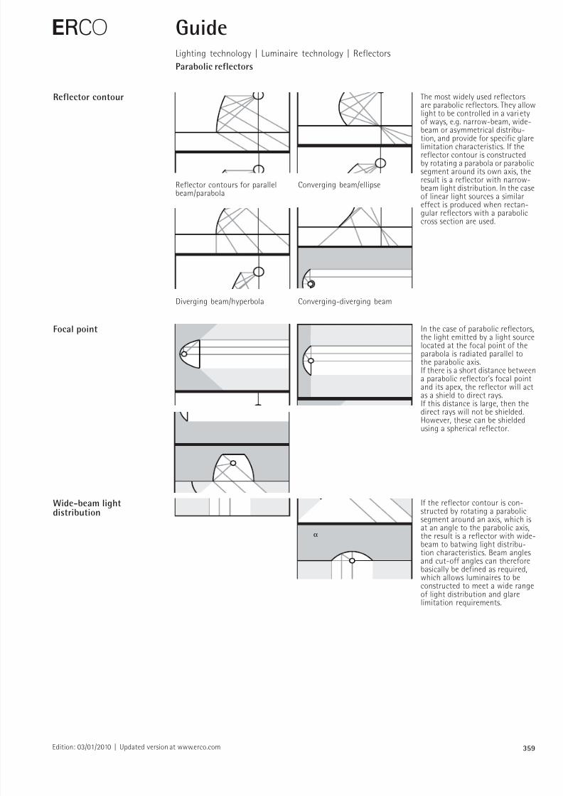
http://slidepdf.com/reader/full/en-erco-guide-6-lighting-technology 42/57
360
1
α
1
α
Edition: 03/01/2010 | Updated version at www.erco.com
E GuideLighting technology | Luminaire technology | Reflectors
Parabolic reflectors
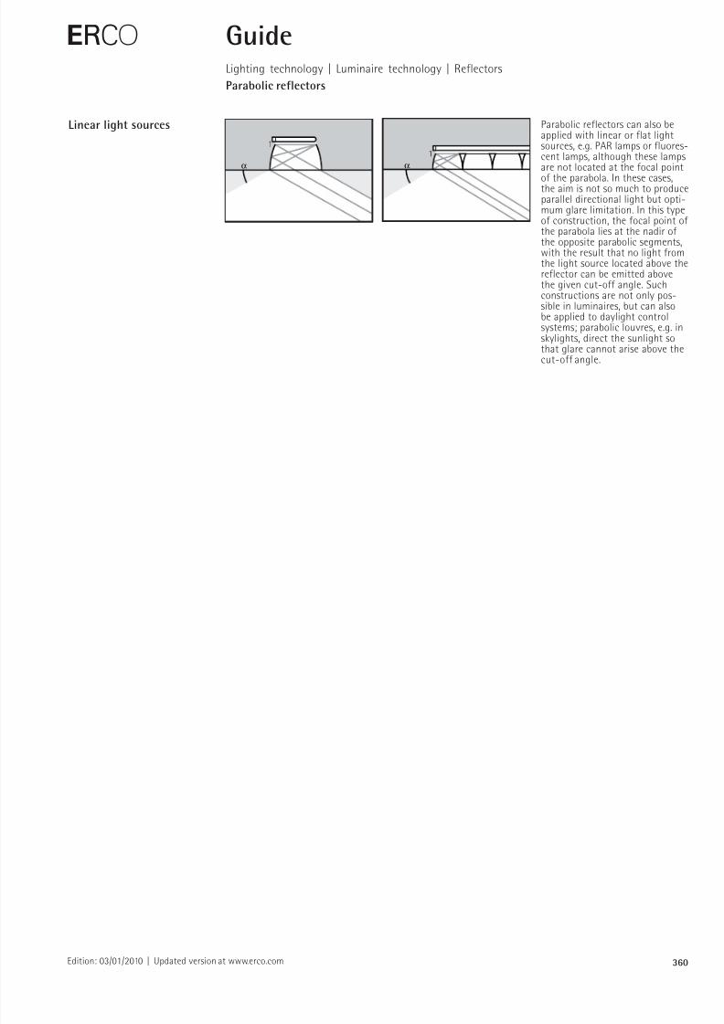
Parabolic reflectors can also beapplied with linear or flat lightsources, e.g. PAR lamps or fluores-cent lamps, although these lampsare not located at the focal point
of the parabola. In these cases,the aim is not so much to produceparallel directional light but opti-mum glare limitation. In this typeof construction, the focal point ofthe parabola lies at the nadir ofthe opposite parabolic segments,with the result that no light fromthe light source located above thereflector can be emitted abovethe given cut-off angle. Suchconstructions are not only pos-sible in luminaires, but can alsobe applied to daylight controlsystems; parabolic louvres, e.g. inskylights, direct the sunlight sothat glare cannot arise above the
cut-off angle.
Linear light sources
8/13/2019 En Erco Guide 6 Lighting Technology
http://slidepdf.com/reader/full/en-erco-guide-6-lighting-technology 43/57
361Edition: 03/01/2010 | Updated version at www.erco.com
E
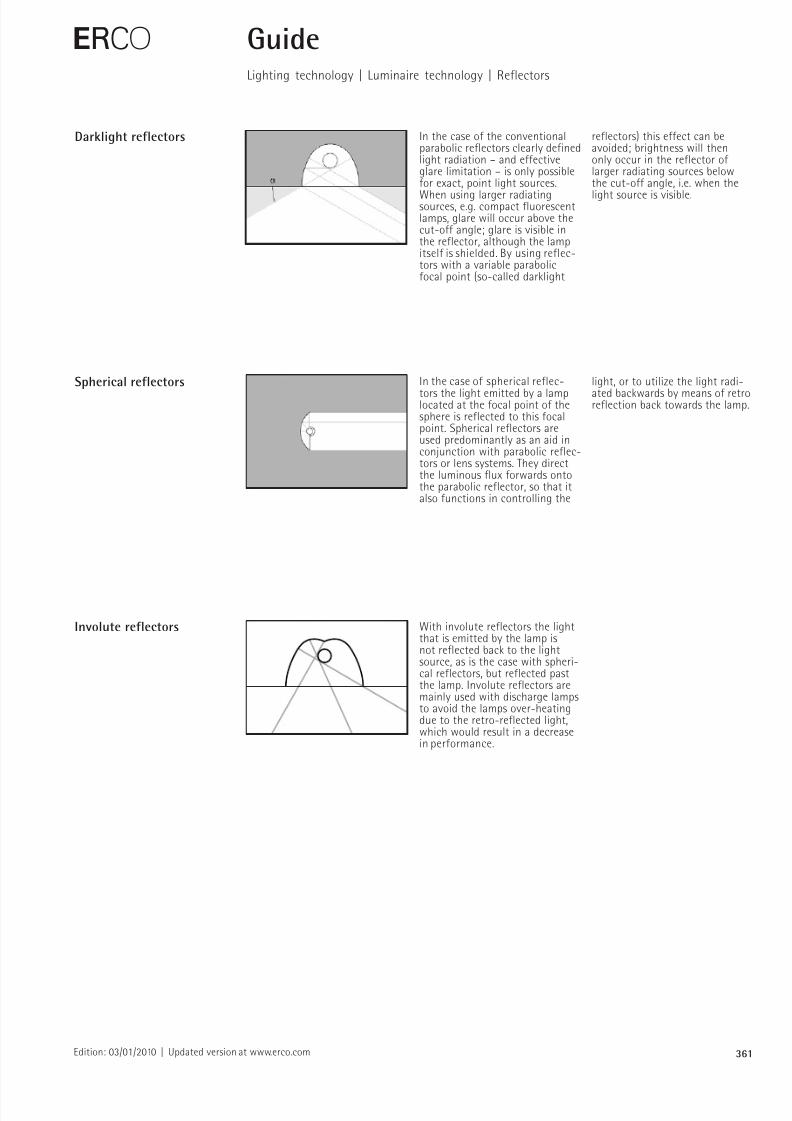
In the case of the conventionalparabolic reflectors clearly definedlight radiation – and effectiveglare limitation – is only possiblefor exact, point light sources.
When using larger radiatingsources, e.g. compact fluorescentlamps, glare will occur above thecut-off angle; glare is visible inthe reflector, although the lampitself is shielded. By using reflec-tors with a variable parabolicfocal point (so-called darklight
GuideLighting technology | Luminaire technology | Reflectors
In the case of spherical reflec-
tors the light emitted by a lamplocated at the focal point of thesphere is reflected to this focalpoint. Spherical reflectors areused predominantly as an aid inconjunction with parabolic reflec-tors or lens systems. They directthe luminous flux forwards ontothe parabolic reflector, so that italso functions in controlling the
Spherical reflectors
With involute reflectors the lightthat is emitted by the lamp isnot reflected back to the lightsource, as is the case with spheri-cal reflectors, but reflected pastthe lamp. Involute reflectors aremainly used with discharge lampsto avoid the lamps over-heatingdue to the retro-reflected light,which would result in a decreasein performance.
Involute reflectors
Darklight reflectors reflectors) this effect can beavoided; brightness will thenonly occur in the reflector oflarger radiating sources belowthe cut-off angle, i.e. when the
light source is visible.
light, or to utilize the light radi-
ated backwards by means of retroreflection back towards the lamp.
8/13/2019 En Erco Guide 6 Lighting Technology
http://slidepdf.com/reader/full/en-erco-guide-6-lighting-technology 44/57
362Edition: 03/01/2010 | Updated version at www.erco.com
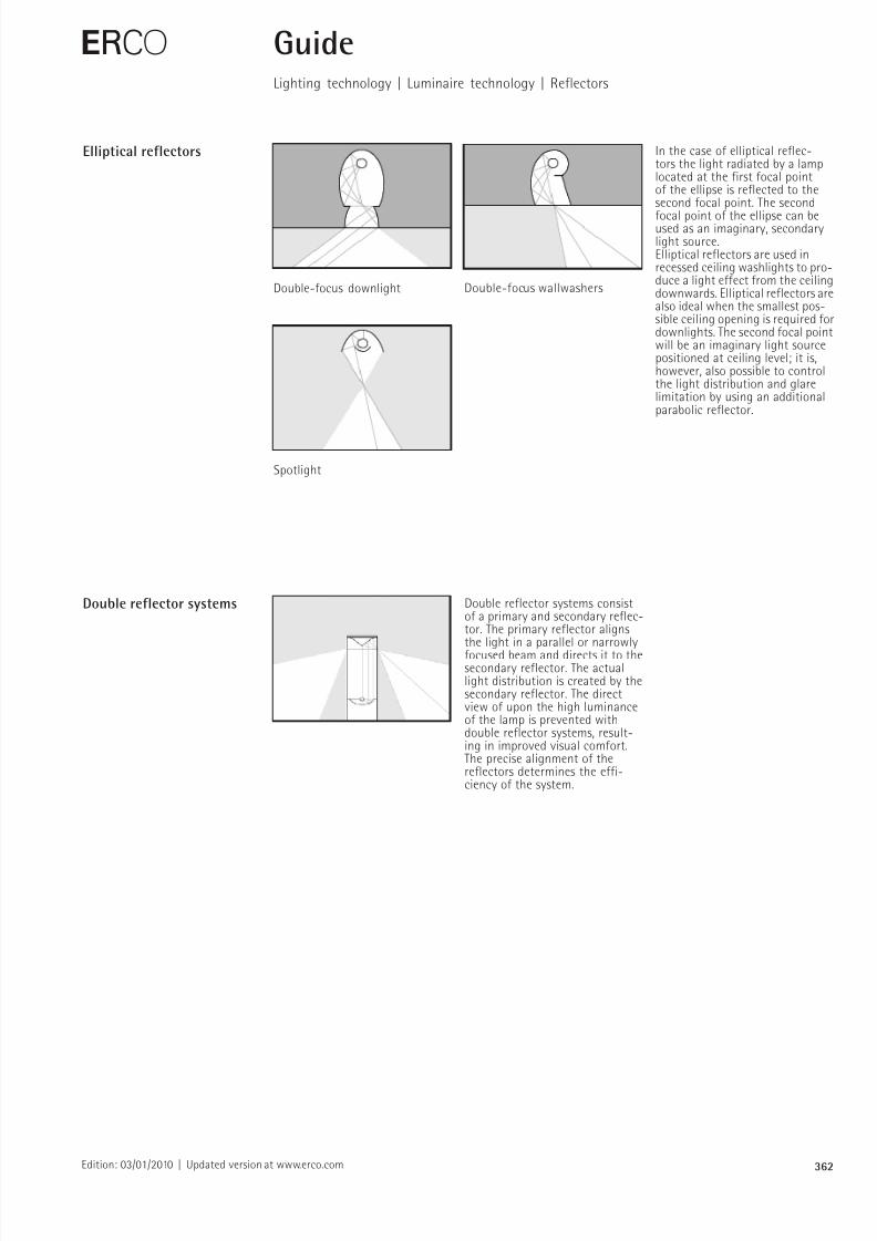
Double reflector systems consistof a primary and secondary reflec-tor. The primary reflector alignsthe light in a parallel or narrowly
focused beam and directs it to thesecondary reflector. The actuallight distribution is created by thesecondary reflector. The directview of upon the high luminanceof the lamp is prevented withdouble reflector systems, result-ing in improved visual comfort.The precise alignment of thereflectors determines the effi-ciency of the system.
Double reflector systems
E GuideLighting technology | Luminaire technology | Reflectors
In the case of elliptical reflec-tors the light radiated by a lamplocated at the first focal pointof the ellipse is reflected to thesecond focal point. The second
focal point of the ellipse can beused as an imaginary, secondarylight source.Elliptical reflectors are used inrecessed ceiling washlights to pro-duce a light effect from the ceilingdownwards. Elliptical reflectors arealso ideal when the smallest pos-sible ceiling opening is required fordownlights. The second focal pointwill be an imaginary light sourcepositioned at ceiling level; it is,however, also possible to controlthe light distribution and glarelimitation by using an additionalparabolic reflector.
Elliptical reflectors
Double-focus downlight Double-focus wallwashers
Spotlight
8/13/2019 En Erco Guide 6 Lighting Technology
http://slidepdf.com/reader/full/en-erco-guide-6-lighting-technology 45/57
363Edition: 03/01/2010 | Updated version at www.erco.com
E
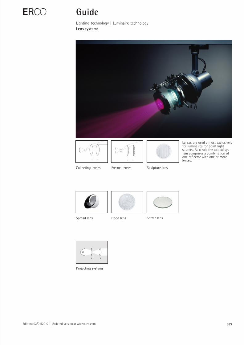
Lenses are used almost exclusivelyfor luminaires for point lightsources. As a rule the optical sys-tem comprises a combination ofone reflector with one or morelenses.
Collecting lenses Sculpture lensFresnel lenses
Spread lens Softec lensFlood lens
Projecting systems
GuideLighting technology | Luminaire technology
Lens systems
8/13/2019 En Erco Guide 6 Lighting Technology
http://slidepdf.com/reader/full/en-erco-guide-6-lighting-technology 46/57
364Edition: 03/01/2010 | Updated version at www.erco.com
E GuideLighting technology | Luminaire technology | Lens systems
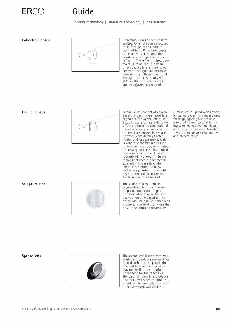
Collecting lenses direct the lightemitted by a light source locatedin its focal point to a parallelbeam of light. Collecting lensesare usually used in luminaire
constructions together with areflector. The reflector directs theoverall luminous flux in beamdirection, the lens is there to con-centrate the light. The distancebetween the collecting lens andthe light source is usually vari-able, so that the beam anglescan be adjusted as required.
Collecting lenses
Fresnel lenses consist of concen-
trically aligned ring-shaped lenssegments. The optical effect ofthese lenses is comparable to theeffect produced by conventionallenses of corresponding shapeor curvature. Fresnel lenses are,however, considerably flatter,lighter and less expensive, whichis why they are frequently usedin luminaire construction in placeof converging lenses. The opticalperformance of Fresnel lensesis confined by aberration in theregions between the segments;as a rule the rear side of thelenses is structured to maskvisible irregularities in the lightdistribution and to ensure thatthe beam contours are soft.
Fresnel lenses Luminaires equipped with Fresnel
lenses were originally mainly usedfor stage lighting but are nowalso used in architectural light-ing schemes to allow individualadjustment of beam angles whenthe distance between luminairesand objects varies.
The sculpture lens producesasymmetrical light distribution.It spreads the beam of light inone axis, while leaving the lightdistribution unchanged on theother axis. The parallel ribbed lensproduces a vertical oval when theribs are orientated horizontally.
Sculpture lens
The spread lens is used with wall-washers. It produces asymmetricallight distribution. It spreads thebeam of light in one axis, whileleaving the light distributionunchanged for the other axis.The parallel ribbed lens producesa vertical oval when the ribs areorientated horizontally. This pro-
duces very even wallwashing.
Spread lens
8/13/2019 En Erco Guide 6 Lighting Technology
http://slidepdf.com/reader/full/en-erco-guide-6-lighting-technology 47/57
365Edition: 03/01/2010 | Updated version at www.erco.com
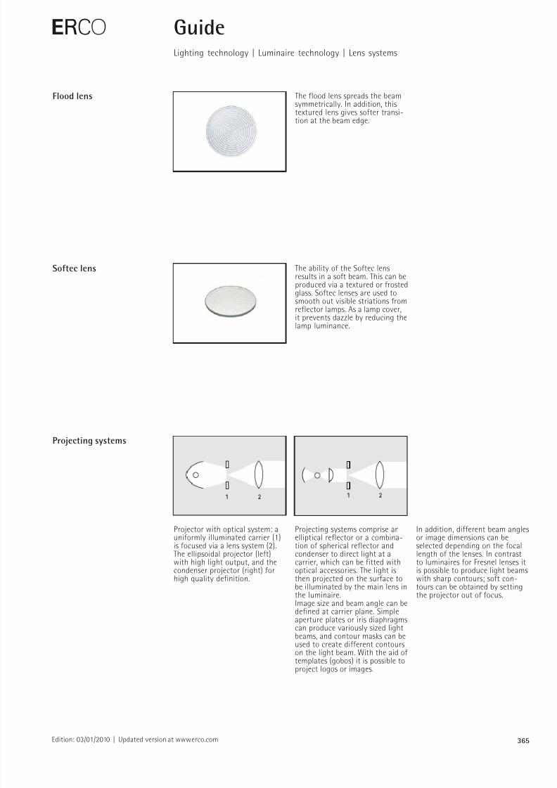
The flood lens spreads the beamsymmetrically. In addition, thistextured lens gives softer transi-tion at the beam edge.
Flood lens
E GuideLighting technology | Luminaire technology | Lens systems
Projecting systems comprise anelliptical reflector or a combina-tion of spherical reflector and
condenser to direct light at acarrier, which can be fitted withoptical accessories. The light isthen projected on the surface tobe illuminated by the main lens inthe luminaire.Image size and beam angle can bedefined at carrier plane. Simpleaperture plates or iris diaphragmscan produce variously sized lightbeams, and contour masks can beused to create different contourson the light beam. With the aid oftemplates (gobos) it is possible toproject logos or images.
Projecting systems
Projector with optical system: auniformly illuminated carrier (1)is focused via a lens system (2).
The ellipsoidal projector (left)with high light output, and thecondenser projector (right) forhigh quality definition.
The ability of the Softec lens
results in a soft beam. This can beproduced via a textured or frostedglass. Softec lenses are used tosmooth out visible striations fromreflector lamps. As a lamp cover,it prevents dazzle by reducing thelamp luminance.
Softec lens
In addition, different beam anglesor image dimensions can beselected depending on the focal
length of the lenses. In contrastto luminaires for Fresnel lenses itis possible to produce light beamswith sharp contours; soft con-tours can be obtained by settingthe projector out of focus.
8/13/2019 En Erco Guide 6 Lighting Technology
http://slidepdf.com/reader/full/en-erco-guide-6-lighting-technology 48/57
366
T (%)100
80
60
20
0
40
8004 00 5 00 700600 nm300
Standard lighttype AT = 47%
T (%)100
80
60
20
0
40
800400 500 700600 nm300
Standard light type AT = 65%
T (%)100
80
60
20
0
40
800400 500 700600 nm300
Standard lighttype AT = 93%
Edition: 03/01/2010 | Updated version at www.erco.com
E
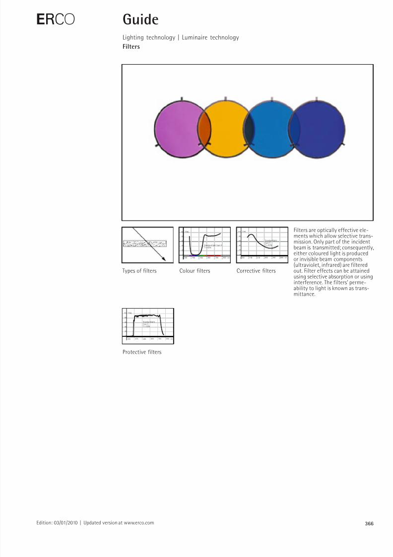
Filters are optically effective ele-ments which allow selective trans-mission. Only part of the incidentbeam is transmitted; consequently,either coloured light is producedor invisible beam components(ultraviolet, infrared) are filteredout. Filter effects can be attainedusing selective absorption or usinginterference. The filters‘ perme-ability to light is known as trans-
mittance.
Types of filters Corrective filtersColour filters
Protective filters
GuideLighting technology | Luminaire technology
Filters
8/13/2019 En Erco Guide 6 Lighting Technology
http://slidepdf.com/reader/full/en-erco-guide-6-lighting-technology 49/57
367
T (%)100
80
60
20
0
40
800400 500 700600 nm300
Standard light type AT = 65%
T (%)100
80
60
20
0
40
800400 500 700600 nm300
Standard light type AT = 38%
T (%)100
80
60
20
0
40
800400 500 700600 nm300
Standard light type AT = 6%
T (%)100
80
60
20
0
40
800400 500 700600 nm300
Standard light type AT = 8%
Edition: 03/01/2010 | Updated version at www.erco.com
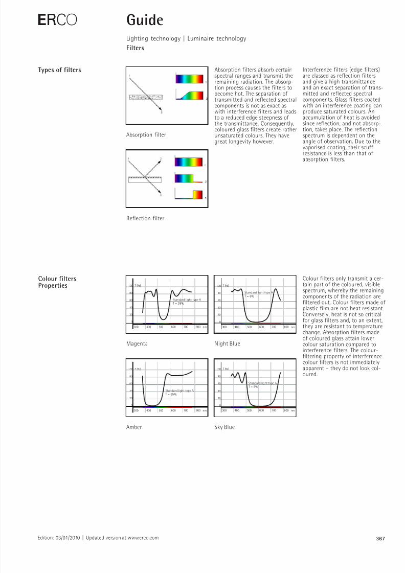
Absorption filters absorb certainspectral ranges and transmit theremaining radiation. The absorp-tion process causes the filters tobecome hot. The separation of
transmitted and reflected spectralcomponents is not as exact aswith interference filters and leadsto a reduced edge steepness ofthe transmittance. Consequently,coloured glass filters create ratherunsaturated colours. They havegreat longevity however.
Types of filters
E GuideLighting technology | Luminaire technology
Filters
Interference filters (edge filters)are classed as reflection filtersand give a high transmittanceand an exact separation of trans-mitted and reflected spectral
components. Glass filters coatedwith an interference coating canproduce saturated colours. Anaccumulation of heat is avoidedsince reflection, and not absorp-tion, takes place. The reflectionspectrum is dependent on theangle of observation. Due to thevaporised coating, their scuffresistance is less than that ofabsorption filters.
Absorption filter
Reflection filter
Magenta
Amber
Colour filters only transmit a cer-tain part of the coloured, visiblespectrum, whereby the remainingcomponents of the radiation are
filtered out. Colour filters made ofplastic film are not heat resistant.Conversely, heat is not so criticalfor glass filters and, to an extent,they are resistant to temperaturechange. Absorption filters madeof coloured glass attain lowercolour saturation compared tointerference filters. The colour-filtering property of interferencecolour filters is not immediatelyapparent – they do not look col-oured.
Colour filtersProperties
Night Blue
Sky Blue
8/13/2019 En Erco Guide 6 Lighting Technology
http://slidepdf.com/reader/full/en-erco-guide-6-lighting-technology 50/57
368
T (%)100
80
60
20
0
40
800400 500 700600 nm300
Standard lighttype AT = 47%
T (%)100
80
60
20
0
40
800400 500 700600 nm300
Standard lighttype AT = 65%
Edition: 03/01/2010 | Updated version at www.erco.com
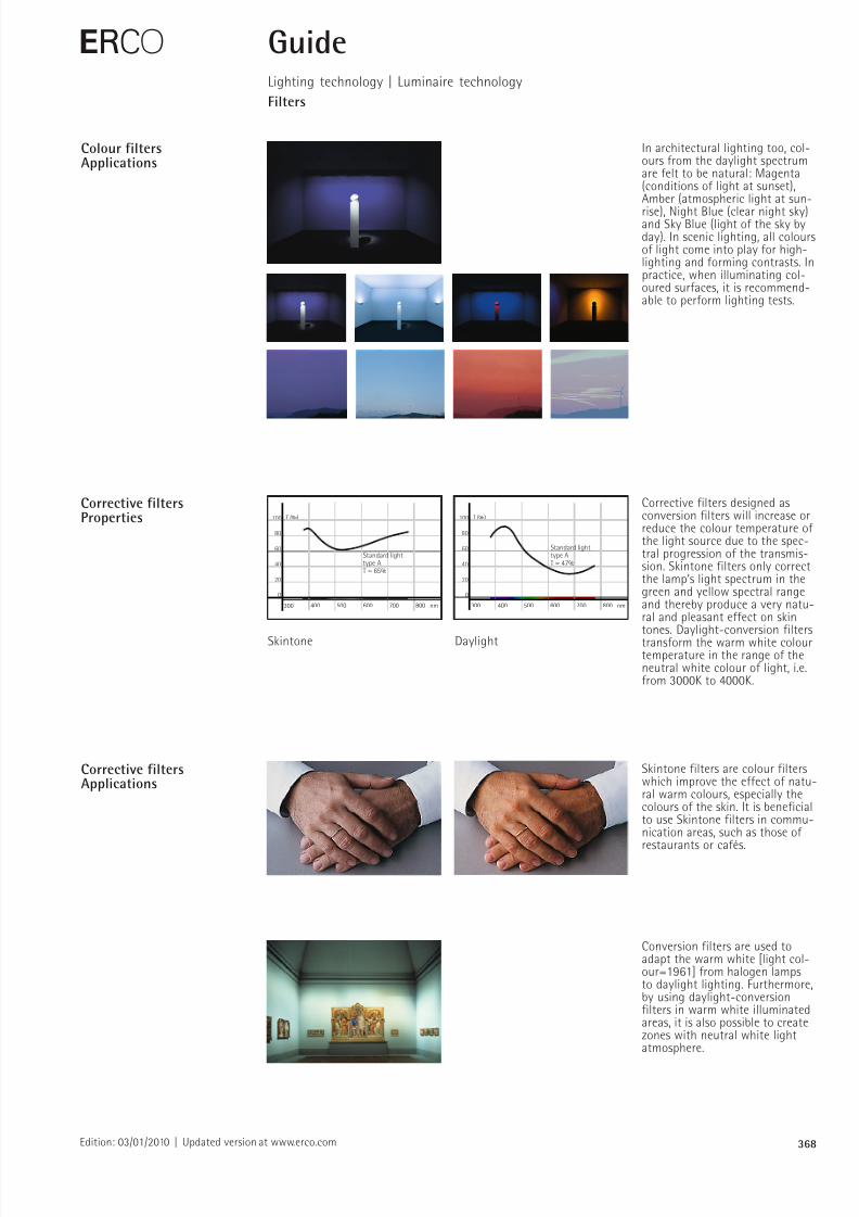
In architectural lighting too, col-ours from the daylight spectrumare felt to be natural: Magenta(conditions of light at sunset),Amber (atmospheric light at sun-
rise), Night Blue (clear night sky)and Sky Blue (light of the sky byday). In scenic lighting, all coloursof light come into play for high-lighting and forming contrasts. Inpractice, when illuminating col-oured surfaces, it is recommend-able to perform lighting tests.
Colour filtersApplications
E GuideLighting technology | Luminaire technology
Filters
Corrective filters designed asconversion filters will increase orreduce the colour temperature ofthe light source due to the spec-tral progression of the transmis-sion. Skintone filters only correctthe lamp‘s light spectrum in thegreen and yellow spectral rangeand thereby produce a very natu-ral and pleasant effect on skintones. Daylight-conversion filters
transform the warm white colourtemperature in the range of theneutral white colour of light, i.e.from 3000K to 4000K.
Corrective filtersProperties
Corrective filtersApplications
Skintone Daylight
Skintone filters are colour filterswhich improve the effect of natu-ral warm colours, especially thecolours of the skin. It is beneficialto use Skintone filters in commu-nication areas, such as those ofrestaurants or cafés.
Conversion filters are used toadapt the warm white [light col-our=1961] from halogen lampsto daylight lighting. Furthermore,by using daylight-conversionfilters in warm white illuminatedareas, it is also possible to createzones with neutral white lightatmosphere.
8/13/2019 En Erco Guide 6 Lighting Technology
http://slidepdf.com/reader/full/en-erco-guide-6-lighting-technology 51/57
369
T (%)100
80
60
20
0
40
800400 500 700600 nm300
Standard lighttype AT = 93%
T (%)100
80
60
20
0
40
800400 500 700600 nm300
Standard lighttype AT = 92%
Edition: 03/01/2010 | Updated version at www.erco.com
E GuideLighting technology | Luminaire technology | Filters
Protective filters
UV filters are suitable for com-pletely blocking ultravioletradiation while allowing optimaltransmission of visible light. Theseparation between reflexion
and transmission takes place at400nm. The steeper the edge ofthe transmission curve, the lessthe will be the colour distortionin the visible spectrum. UV filtersare transparent (clear), the trans-mission is directional.
Properties
UV filter
IR filter
Applications Filtering out virtually all the ultra-violet radiation effectively delaysthe photochemical process ofdecay in textiles, watercolours,
historic documents, artworks andother exhibits that are sensitiveto light. This particularly appliesto the bleaching of colours and toyellowing. In practice, since theUV component of high-pressuredischarge lamps is already reducedby prescribed safety glasses,the highest ultraviolet loadingis found from non-capsulatedtungsten halogen lamps.
The use of infrared filters signifi-cantly reduces the thermal loadand thus decreases the heat onan object or its surface. Materialssensitive to heat and humiditycan thus be protected from dryingout or distorting. High propor-tions of infrared radiation areemitted predominantly from lightsources with low luminous effi-cacy, such as thermal radiators.
Infrared filters absorb or reflectthe thermal radiation above800nm while allowing optimaltransmission of visible lightspectrum. The thermal load onobjects is reduced to a minimum.IR filters are transparent (clear),the transmission is directional.
Adequate seperation betweenlamp and filter avoids a build-upof heat within the luminaire.
UV filters are suitable for use in:- art museums- art galleries- natural-science museums
- antiquarian bookshops
IR filters are suitable for use in:- art museums- art galleries- natural-science museums- antiquarian bookshops- food shops
UV filter
IR filter
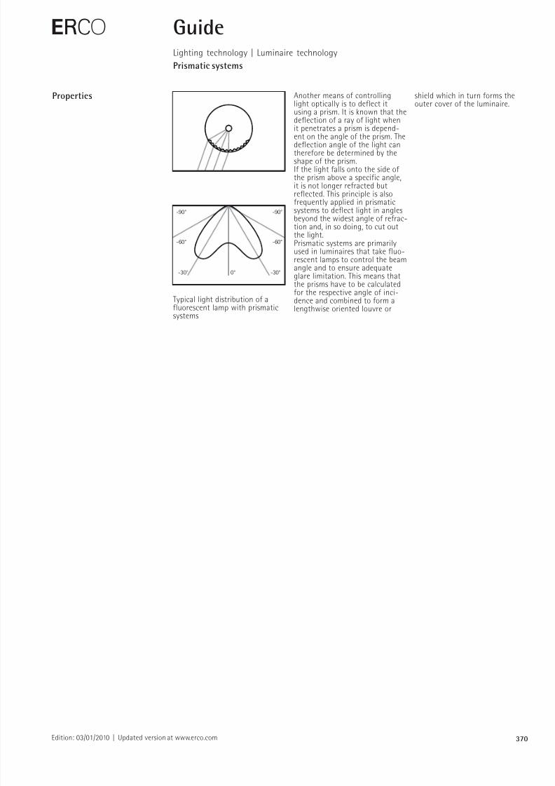
8/13/2019 En Erco Guide 6 Lighting Technology
http://slidepdf.com/reader/full/en-erco-guide-6-lighting-technology 52/57
370
-30°0°-30°
-60°-60°
-90°-90°
Edition: 03/01/2010 | Updated version at www.erco.com
E GuideLighting technology | Luminaire technology
Prismatic systems
Properties
Typical light distribution of afluorescent lamp with prismaticsystems
Another means of controllinglight optically is to deflect itusing a prism. It is known that thedeflection of a ray of light whenit penetrates a prism is depend-
ent on the angle of the prism. Thedeflection angle of the light cantherefore be determined by theshape of the prism.If the light falls onto the side ofthe prism above a specific angle,it is not longer refracted butreflected. This principle is alsofrequently applied in prismaticsystems to deflect light in anglesbeyond the widest angle of refrac-tion and, in so doing, to cut outthe light.Prismatic systems are primarilyused in luminaires that take fluo-rescent lamps to control the beamangle and to ensure adequate
glare limitation. This means thatthe prisms have to be calculatedfor the respective angle of inci-dence and combined to form alengthwise oriented louvre or
shield which in turn forms theouter cover of the luminaire.
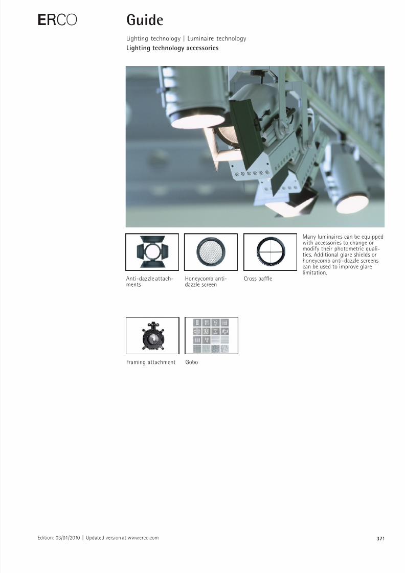
8/13/2019 En Erco Guide 6 Lighting Technology
http://slidepdf.com/reader/full/en-erco-guide-6-lighting-technology 53/57
371Edition: 03/01/2010 | Updated version at www.erco.com
E
Many luminaires can be equippedwith accessories to change ormodify their photometric quali-ties. Additional glare shields orhoneycomb anti-dazzle screenscan be used to improve glarelimitation.
Anti-dazzle attach-ments
Cross baffleHoneycomb anti-dazzle screen
Framing attachment
GuideLighting technology | Luminaire technology
Lighting technology accessories
Gobo
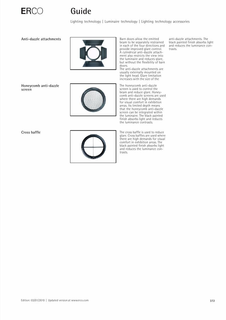
8/13/2019 En Erco Guide 6 Lighting Technology
http://slidepdf.com/reader/full/en-erco-guide-6-lighting-technology 54/57
372Edition: 03/01/2010 | Updated version at www.erco.com
E GuideLighting technology | Luminaire technology | Lighting technology accessories
Anti-dazzle attachments Barn doors allow the emittedbeam to be separately restrainedin each of the four directions andprovide improved glare control.A cylindrical anti-dazzle attach-
ment also restricts the view intothe luminaire and reduces glare,but without the flexibility of barndoors.The anti-dazzle attachments areusually externally mounted onthe light head. Glare limitationincreases with the size of the
anti-dazzle attachments. Theblack painted finish absorbs lightand reduces the luminance con-trasts.
Honeycomb anti-dazzlescreen
The honeycomb anti-dazzlescreen is used to control thebeam and reduce glare. Honey-comb anti-dazzle screens are usedwhere there are high demandsfor visual comfort in exhibitionareas. Its limited depth meansthat the honeycomb anti-dazzle
screen can be integrated withinthe luminaire. The black paintedfinish absorbs light and reducesthe luminance contrasts.
Cross baffle The cross baffle is used to reduceglare. Cross baffles are used wherethere are high demands for visualcomfort in exhibition areas. Theblack painted finish absorbs lightand reduces the luminance con-trasts.
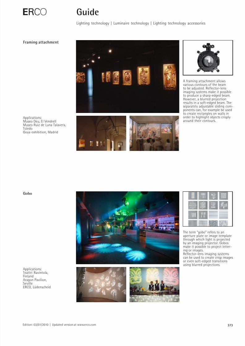
8/13/2019 En Erco Guide 6 Lighting Technology
http://slidepdf.com/reader/full/en-erco-guide-6-lighting-technology 55/57
373Edition: 03/01/2010 | Updated version at www.erco.com
Framing attachment
A framing attachment allowsvarious contours of the beamto be adjusted. Reflector-lensimaging systems make it possibleto produce a sharp-edged beam.However, a blurred projectionresults in a soft-edged beam. Theseparately adjustable sliding com-ponents can, for example be usedto create rectangles on walls inorder to highlight objects crisply
around their contours.
Applications:
Museo Deu, El VendrellMuseo Ruiz de Luna Talavera,ToledoGoya exhibition, Madrid
Gobo
The term “gobo“ refers to anaperture plate or image templatethrough which light is projected
by an imaging projector. Gobosmake it possible to project letter-ing or images.Reflector-lens imaging systemscan be used to create crisp imagesor even soft-edged transitionsusing blurred projections.
E GuideLighting technology | Luminaire technology | Lighting technology accessories
Applications:Teattri Ravintola,FinlandAragon Pavilion,SevilleERCO, Lüdenscheid
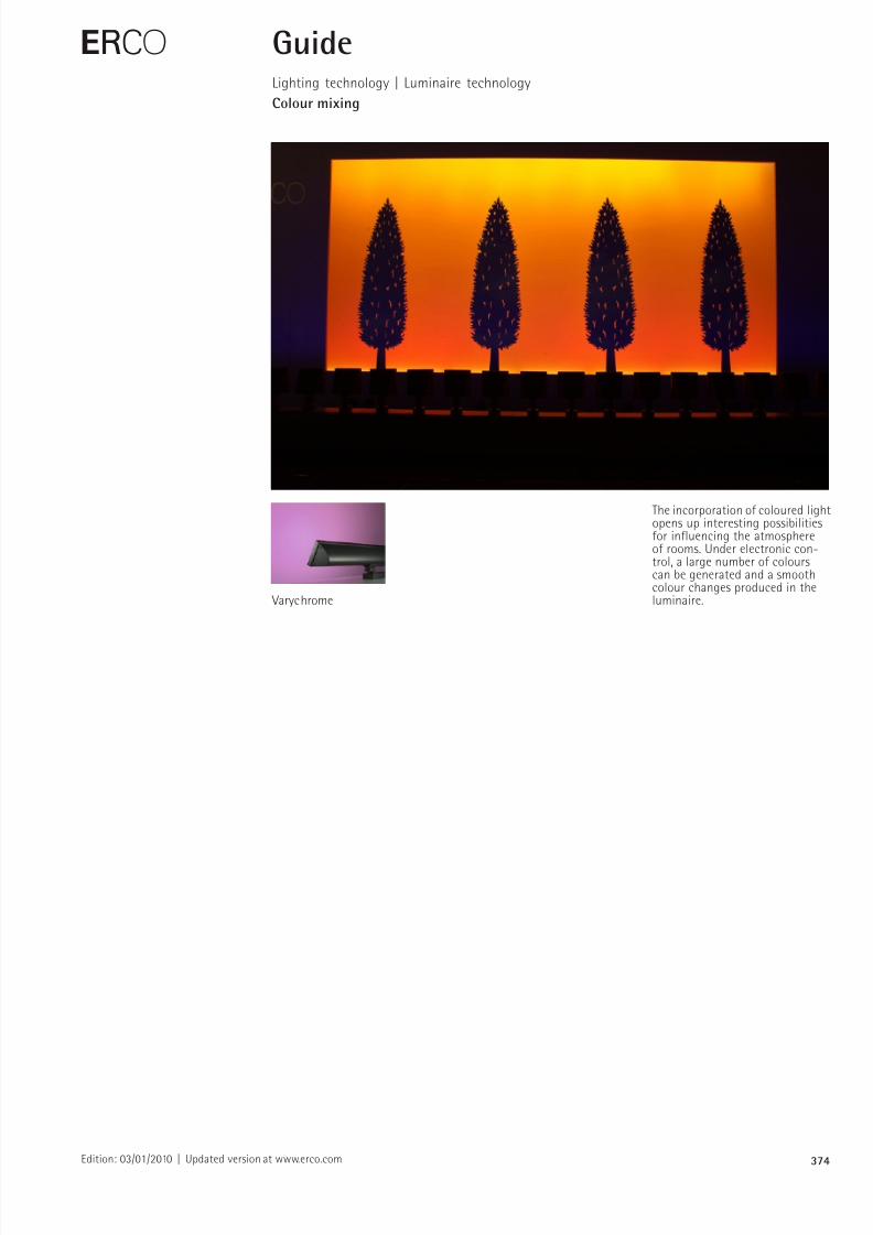
8/13/2019 En Erco Guide 6 Lighting Technology
http://slidepdf.com/reader/full/en-erco-guide-6-lighting-technology 56/57
374Edition: 03/01/2010 | Updated version at www.erco.com
E
The incorporation of coloured lightopens up interesting possibilitiesfor influencing the atmosphereof rooms. Under electronic con-trol, a large number of colourscan be generated and a smoothcolour changes produced in theluminaire. Varychrome
GuideLighting technology | Luminaire technology
Colour mixing
8/13/2019 En Erco Guide 6 Lighting Technology
http://slidepdf.com/reader/full/en-erco-guide-6-lighting-technology 57/57
Introduction The addition of the name ‚vary-chrome‘ to ERCO luminaires iden-tifies those luminairs whose col-our can be changed dynamically.These luminaires are electronically
controlled to generate variablelight colours by additive colourmixing of the primary colours red,green and blue (RGB technology).They enable an infinitely variableadjustment of different lightcolours.The advantages of colour mixingusing coloured lamps are thatcomplex mechanical componentsare not needed and colour filterswith low transmission are avoided.The term ‚varychrome‘ refers tothe mixing of colours.It is derived from the Latin adjec-tive ‚varius‘ meaning differentand the Greek word ‚chroma‘ for
colour.
E GuideLighting technology | Luminaire technology | Colour mixing
Varychrome
Technology In principle, the colours of thefluorescent lamps can be chosenat will. A multitude of colourscan be mixed from the colouredfluorescent lamps in red, greenand blue. The saturation andthe chromaticity location of thelamps determine the size andshape of the resulting colour tri-angle. The lamps in warm white,neutral white and daylight white
can create various different whitelight colours. The fluorescentlamps primarily produce diffuselight with low brilliance.
LED
The luminaires with LEDs featurea high colour density, whichtherefore results in a large colourtriangles. Characteristic for LEDsare low luminous flux, compactdimensions and long service life.
Fluorescent lamps

![[Architecture Ebook] ERCO Handbook of Lighting Design](https://static.fdocuments.net/doc/165x107/553d7a8f550346fb2c8b46fa/architecture-ebook-erco-handbook-of-lighting-design.jpg)