EN 61558-1:2005 (ed.2) + A1:2009 EN 61558-2-16:2009 EN 61558-2 … · · 2017-07-06The test...
76
The test result refers exclusively to the model tested. This report must not be copied without the written authorization by the lab. EN 61558-1:2005 (ed.2) + A1:2009 EN 61558-2-16:2009 EN 61558-2-4:2009 Safety of power transforers, power supplies, reactors and similar products – Safety – 110423-AU02+S02 Quantum Glass – Saint Gobain – France switching power supply SMPS 110VAC-S 80VA U Customer: Quantum Glass – Saint Gobain - France 4, Passage Sainte Avoye / 8 rue Rambuteau 75003 Paris France
Transcript of EN 61558-1:2005 (ed.2) + A1:2009 EN 61558-2-16:2009 EN 61558-2 … · · 2017-07-06The test...

The test result refers exclusively to the model tested.
This report must not be copied without
the written authorization by the lab.
EN 61558-1:2005 (ed.2) + A1:2009
EN 61558-2-16:2009
EN 61558-2-4:2009
Safety of power transforers, power
supplies, reactors and similar products
– Safety –
110423-AU02+S02
Quantum Glass – Saint Gobain – France
switching power supply
SMPS 110VAC-S 80VA U
Customer:
Quantum Glass – Saint Gobain - France 4, Passage Sainte Avoye / 8 rue Rambuteau
75003 Paris France

EMV TESTHAUS GmbH
Gustav-Hertz-Strasse 35 94315 Straubing
Germany
Revision 1.0
Quantum Glass – Saint Gobain - France
switching power supply / SMPS 110VAC S 80VA U
110423-AU02+S02 Page 2 of 76
TEST REPORTS
EN 61558-1:2005 (ed.2) + A1:2009 / EN 61558-2-16:2009 / EN 61558-2-4:2009
Safety of power transforers, power supplies, reactors and similar products
Part 1: General requirements and tests
Part 2-16: Particular requirements and tests for switch mode power supply units and
transformers for switch mode power supply units
Part 2-4: Particular requirements and tests for isolating transformers and power supply
units incorporating isolating transformers
Report reference No . ..................... : 110423-AU02+S02
Tested by (printed name and signature) .......... :
Richard Gierl
.....................................................
Approved by (printed name and signature) .......... :
Alexander Fischer
.....................................................
Date of issue ................................... : 2012-07-18
Testing Laboratory Name ............. : EMV Testhaus GmbH
Address ........................................... :
Gustav-Hertz-Straße 35 D-94315 Straubing Germany
Telephone: ...... +49 (0)9421-56868-0
Fax: ................. +49 (0)9421-56868-100
Applicant's Name .......................... : Quantum Glass – Saint Gobain - France
Address ........................................... : 4, Passage Sainte Avoye / 8 rue Rambuteau
.......................................................... : 75003 Paris
France
Test specification
Standard ........................................... : EN 61558-1:2005 (ed.2) + A1:2009 / EN 61558-2-16:2009 /
EN 61558-2-4:2009
Test procedure ................................ : CE conformity test This test report is only valid with test report no. 110423-AU02+S01.
Non-standard test method ............... : N/A
Test item description .................... : Switching Power Supply
Trademark ....................................... : Quantum Glass – Saint Gobain - France
Manufacturer ................................... : SCHIEDERWERK GmbH & Co.KG
Model and/or type reference ........... : SMPS 110VAC-S 80VA U
Serial number .................................. : *00015*
Rating(s) ........................................... : Voltage: 110-230VAC / Frequency: 50-60 Hz / Current: 1.2-0.4 A

EMV TESTHAUS GmbH
Gustav-Hertz-Strasse 35 94315 Straubing
Germany
Revision 1.0
Quantum Glass – Saint Gobain - France
switching power supply / SMPS 110VAC S 80VA U
110423-AU02+S02 Page 3 of 76
General product information:
The EUT is a class I power supply unit. Equipment is single-phase alternating current supplied.
Output voltage of PSU: 100V AC (secondary circuit with hazardous voltages)
Equipment is for building-in.
Copy of marking plate:

EMV TESTHAUS GmbH
Gustav-Hertz-Strasse 35 94315 Straubing
Germany
Revision 1.0
Quantum Glass – Saint Gobain - France
switching power supply / SMPS 110VAC S 80VA U
110423-AU02+S02 Page 4 of 76
Particulars: test item vs. test requirements
Equipment mobility ..................................... : Stationary Equipment
Operating condition ..................................... : continuous
Mains supply tolerance (%) ......................... : +6% / -10%
Tested for IT power systems ...................... : Tested for TN system
IT testing, phase-phase voltage (V) ........... : - -
Class of equipment ..................................... : Class I Equipment
Mass of equipment (kg) ............................... : 780g
Protection against ingress of water ............ : No IP20
Test case verdicts
Test clause not tested ................................ : N/T
Test case does not apply to the test object : N/A
Test item does meet the requirement ........ : P(ass)
Test item does not meet the requirement .. : F(ail)
Testing
Date of receipt of test item ......................... : 2012-07-10
Date(s) of performance of test ................... : 2012 week 27-29
Summary of testing (remarks):
System tested with 110-230VAC, (according to first manufacturer information)
The equipment is in compliance with the requirements with EN 61558-1 / EN 61558-2-4 / EN 61558-2-16.
For further measurements (e.g. fault condition tests) refer to test report according to EN 60950-1.
This test report is only valid with test report no. 110423-AU02+S02.

EMV TESTHAUS GmbH
Gustav-Hertz-Strasse 35 94315 Straubing
Germany
Revision 1.0
Quantum Glass – Saint Gobain - France
switching power supply / SMPS 110VAC S 80VA U
110423-AU02+S02 Page 5 of 76
Test Report EN 61558-1
Clause Requirement + Test Result - Remark Verdict
P F N/A N/T
8 MARKING AND OTHER INFORMATION X
8.1 Transformer marked with: X
a) rated supply voltage or voltage range (V) .................................................... :
110-240VAC X
b) rated output voltage (V) ................... : 100VAC X
c) rated output (VA, kVA or W) ............ : 80VA X
d) rated output current (A) ................... : 0,8A X
e) rated frequency (Hz) ........................ : 50-60Hz X
f) rated power factor (if not 1) ............. : cos > 0,92 X
g) symbol AC for alternating current, or DC for direct current-output
AC X
h) symbol for electrical function (according to one or more part’s 2)
Symbol for transformer X
i) manufacturer's name or trademark or name of the responsible vendor
QUANTUM GLASS SAINT-GOBAIN
SCHIEDERWERK
X
j) model or type reference PRIVA-LITE Power Supply Unit QG 06
SMPS 110VAC-S 80VAU
X
k) vector group according to IEC 60076 for three-phase transformer
X
l) symbol for Class II
X
m) symbol for Class III
X
n) index IPXX if other than IP00 IP20 X
o) rated max. ambient temperature ta (if not 25 °C) ........................................ :
X
p) rated minimum ambient temperature ta min, if <10° C and if a temperature sensitive device is used
X
q) short-time duty cycle: operating time Intermittent duty cycle: operating and resting time (e.g. 5min/30min)
X
r) for tw-marked transformers marked with the rated max. operating temperature, increased by multiples of 5 (e.g. tw 120; tw 125 )
X

EMV TESTHAUS GmbH
Gustav-Hertz-Strasse 35 94315 Straubing
Germany
Revision 1.0
Quantum Glass – Saint Gobain - France
switching power supply / SMPS 110VAC S 80VA U
110423-AU02+S02 Page 6 of 76
Test Report EN 61558-1
Clause Requirement + Test Result - Remark Verdict
P F N/A N/T
s) transformers used with forced air cooling shall be marked with “AF” in m/s
X
t) Information from the manufacturer to the purchaser (data sheet) :
X
– short-circuit voltage (% rated supply voltage) for stationary transformers > 1000 VA
X
– electrical function of the transformer
X
8.2 Marking for transformers IP00 or for associated transformers: type and trademark, instruction sheets
X
8.3 Adjusted voltage easily and clearly discernible
No voltage selector. X
8.4 For each tapping or winding: rated output voltage and rated output
X
necessary connections clearly indicated X
8.5 For short-circuit proof transformers or non-inherently short-circuit proof transformers:
T1.6A 250V used X
Rated current (A or mA) and symbol for time cur-rent characteristics of the fuses for non-inherently short-circuit proof transformer with incorporated fuses and non-short-circuit proof transformer ......................... :
X
Manufacturer's model or type reference and rating of the device for non-inherently short-circuit proof transformers with incorporated replaceable protective device (other than fuses)
X
Construction sheet for transformers with replaceable protective device (other than fuses) information with information about the replacement.
X
8.6 Terminals for neutral: "N" Terminal for neutral is marked with ”N”.
X
Terminal for protective earth marked with earthing symbol
X
Identification of input terminals: "PRI" X
Identification of output terminals: "SEC" X

EMV TESTHAUS GmbH
Gustav-Hertz-Strasse 35 94315 Straubing
Germany
Revision 1.0
Quantum Glass – Saint Gobain - France
switching power supply / SMPS 110VAC S 80VA U
110423-AU02+S02 Page 7 of 76
Test Report EN 61558-1
Clause Requirement + Test Result - Remark Verdict
P F N/A N/T
Symbol for any point/terminal in connection with frame or core
X
8.7 Indication for correct connection X
8.8 Instruction sheet for type X, Y, Z attachments
Without power cord. X
8.9 Transformer for indoor use shall be marked with the relevant symbol.
X
8.10 Symbol for Class II construction not confused with maker's name or trademark.
X
Class II transformer with parts to be mounted – delivered with all parts for class II after mounting.
X
Symbol for class II transformer placed on the part which provides class II.
X
8.11 Correct symbols: X
Volts V X
Amperes A (mA) X
Volt amperes (or volt-amperes reactive for reactors)
VA or (VAR) X
Watts W X
Hertz Hz X
Input PRI X
Output SEC X
Direct current d.c. (DC) or X
Neutral N X
Single-phase a.c. X
Three-phase a.c. 3 X
Three-phase and neutral a.c. 3/N X
Power factor cos
Class II construction
X
Class III construction
X
Fuse-link F X
Rated max. ambient temperature ta

EMV TESTHAUS GmbH
Gustav-Hertz-Strasse 35 94315 Straubing
Germany
Revision 1.0
Quantum Glass – Saint Gobain - France
switching power supply / SMPS 110VAC S 80VA U
110423-AU02+S02 Page 8 of 76
Test Report EN 61558-1
Clause Requirement + Test Result - Remark Verdict
P F N/A N/T
Frame or core terminal
X
Protective earth
X
IP number IPXX X
Earth (ground for functional earth)
X
For indoor use only
X
tw5 YYY X
tw10 YYY X
twx YYY X
8.12 Figures, letters or other visual means for different positions of regulating devices and switches
X
OFF position indicated by figure 0 X
Greater output, input etc. indicated by higher figure
X
8.13 Marking not on screws or other easily removable parts
Markings are not on such parts. X
Marking clearly discernible (transformer ready for use)
X
Marking for terminals clearly discernible if necessary after removal of the cover
Removal of cover not required. X
Marking for terminals: no confusion between input and output
No confusion. X
Marking for interchangeable protective devices positioned adjacent to the base
Markings for fuse are placed near the fuse.
X
Marking for interchangeable protective devices clearly discernible after removal of cover and protective device
X
8.14 Special information for installation (in the catalogue, data sheet, or instruction sheet) if necessary:
X
For non-inherently short-circuit proof transformers with non-self-resetting or non replaceable devices (weak-point, thermal link):
The device can not be resettled or replaced
X
EMV TESTHAUS GmbH
Gustav-Hertz-Strasse 35 94315 Straubing
Germany
Revision 1.0
Quantum Glass – Saint Gobain - France
switching power supply / SMPS 110VAC S 80VA U
110423-AU02+S02 Page 9 of 76
Test Report EN 61558-1
Clause Requirement + Test Result - Remark Verdict
P F N/A N/T
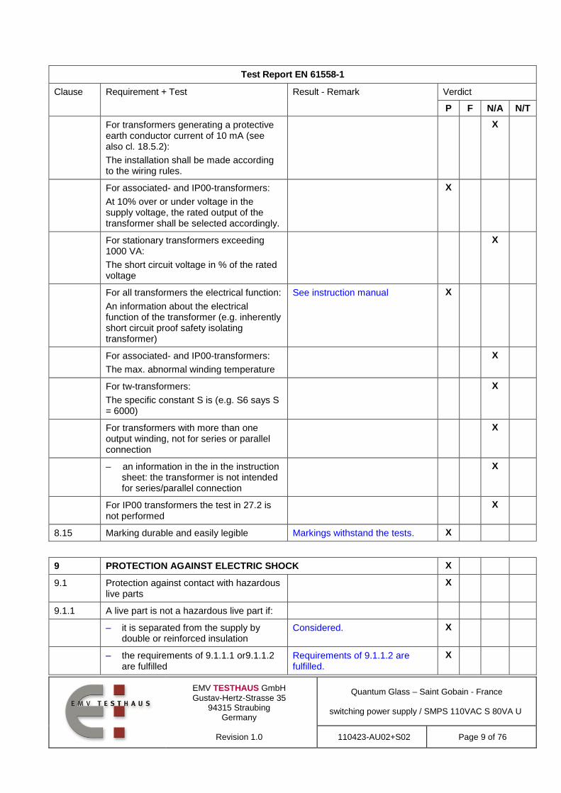
For transformers generating a protective earth conductor current of 10 mA (see also cl. 18.5.2):
The installation shall be made according to the wiring rules.
X
For associated- and IP00-transformers:
At 10% over or under voltage in the supply voltage, the rated output of the transformer shall be selected accordingly.
X
For stationary transformers exceeding 1000 VA:
The short circuit voltage in % of the rated voltage
X
For all transformers the electrical function:
An information about the electrical function of the transformer (e.g. inherently short circuit proof safety isolating transformer)
See instruction manual X
For associated- and IP00-transformers:
The max. abnormal winding temperature
X
For tw-transformers:
The specific constant S is (e.g. S6 says S = 6000)
X
For transformers with more than one output winding, not for series or parallel connection
X
– an information in the in the instruction sheet: the transformer is not intended for series/parallel connection
X
For IP00 transformers the test in 27.2 is not performed
X
8.15 Marking durable and easily legible Markings withstand the tests. X
9 PROTECTION AGAINST ELECTRIC SHOCK X
9.1 Protection against contact with hazardous live parts
X
9.1.1 A live part is not a hazardous live part if:
– it is separated from the supply by double or reinforced insulation
Considered. X
– the requirements of 9.1.1.1 or9.1.1.2 are fulfilled
Requirements of 9.1.1.2 are fulfilled.
X

EMV TESTHAUS GmbH
Gustav-Hertz-Strasse 35 94315 Straubing
Germany
Revision 1.0
Quantum Glass – Saint Gobain - France
switching power supply / SMPS 110VAC S 80VA U
110423-AU02+S02 Page 10 of 76
Test Report EN 61558-1
Clause Requirement + Test Result - Remark Verdict
P F N/A N/T
9.1.1.1 The touch voltage is <35 V(peak) a.c. or < 60 Vd.c.
X
9.1.1.2 If the touch voltage is > 35 V(peak) a.c. or > 60 V d.c., the following requirements shall be fulfilled:
X
The touch current shall not exceed: X
– for a.c. 0,7 mA (peak) Max. touch current 0,036mA. X
– for d.c. 2,0 mA (see Annex J) X
In addition, when a capacitor is connected to live parts:
X
9.1.1.2.1 discharge: < 45 C (between 60 V and 15 kV)
<45µC X
9.1.1.2.2 energy: < 350 mJ (voltage >15 kV) Less than 15kV. X
– for a.c. 0,7 mA (peak) X
9.1.2 Transformers shall have an adequate protection against accessibility to hazardous live parts:
Metal enclosure is used. X
The enclosure of class I and class II transformers gives an adequate protection against accentual contact with hazardous live parts.
Metal enclosure is used. X
Class I transformers: accessible parts are separated from hazardous live parts by at least basic insulation.
Min. basic insulation is used. X
Class II transformers: no accessibility to basic insulation, or conductive parts separated from hazardous live parts by basic insulation.
Class I transformer. X
Hazardous live parts are not accessible after removal of detachable parts.
No detachable parts. X
Hazardous live parts are not accessible after removal of detachable parts except for:
X
– lamps having caps larger B9 and E10 X
– type D fuse holder X
Lacquers, enamel, paper, cotton, oxide film on metal parts not used for protection against accidental contact with hazardous live parts:
No lacquers, enamel, paper, cotton, oxide film on metal parts are used for protection against accidental contact with hazardous live parts.
X

EMV TESTHAUS GmbH
Gustav-Hertz-Strasse 35 94315 Straubing
Germany
Revision 1.0
Quantum Glass – Saint Gobain - France
switching power supply / SMPS 110VAC S 80VA U
110423-AU02+S02 Page 11 of 76
Test Report EN 61558-1
Clause Requirement + Test Result - Remark Verdict
P F N/A N/T
Shafts, handles, operating levers, knops are not hazardous life parts.
No shafts, handles operating levers, knops which are hazardous life parts.
X
Compliance is checked by inspection and by relevant tests according to IEC 60529
Considered X
Class II transformers and Class II parts of Class I construction are tested with the test pin (fig. 3)
All enclosure parts are connected to protective earh.
X
Hazardous live parts shall not be touchable by test finger (fig. 2)
X
for Class II transformers: metal parts separated by basic insulation from hazardous live parts not touchable by test finger
X
hazardous live parts shall not be touchable with the test pin
X
9.1.3 Accessibility of non hazardous live parts No such parts. X
Non hazardous live parts of the output circuit may be accessible if they are isolated from the input circuit by double or reinforced insulation and if the following conditions are fulfilled:
X
– The no load output voltage is < 35 V peak a.c. or < 60 V ripple free d.c., both poles are accessible
X
– The no load output voltage is > 35 V peak a.c. or > 60 V ripple free d.c. and < 250 V a.c., only one pole may be accessible
X
9.2 Transformers with primary supply plug: 1 s after the interruption of the supply the voltage between the pins do not exceed 35 V (peak) a.c. or 60 V ripple free d.c.
No primarysupply plug. X
Transformers without a primary supply plug: 5 s after the interruption of the supply the voltage between the input terminals do not exceed 35 V (peak) a.c. or 60 V ripple free d.c.
X
The following tests are required : X
If the nominal capacitance is < 0,1 µF – no test is conducted.
X

EMV TESTHAUS GmbH
Gustav-Hertz-Strasse 35 94315 Straubing
Germany
Revision 1.0
Quantum Glass – Saint Gobain - France
switching power supply / SMPS 110VAC S 80VA U
110423-AU02+S02 Page 12 of 76
Test Report EN 61558-1
Clause Requirement + Test Result - Remark Verdict
P F N/A N/T
– 10 times switch the supply source on and off, or use a special equipment for to switch off at the most unfavourable electrical angle
Primary voltage under 60 V in 40ms.
X
If the measured voltage is > 60 V ripple free d.c., the discharge must be < 45 µC.
X
10 CHANGE OF INPUT VOLTAGE SETTING X
Voltage setting not possible to change without a tool
No voltage setting. X
Different rated supply voltages: X
– indication of voltage for which the transformer is set, is discernible on the transformer.
X
11 OUTPUT VOLTAGE AND OUTPUT CURRENT UNDER LOAD X
11.1 Difference from rated value (without rectifier; with rectifier):
No such transformer. X
a) inherently short-circuit proof transformers with one rated output
voltage for output voltage: a.c. 10%
; d.c. 15%
No such transformer. X
b) inherently short-circuit proof transformers with one more than 1 rated output voltage for highest output
voltage: a.c. 10%; d.c. 15%
No such transformer. X
c) idem for other output voltages: a.c.
15%; d.c. 20%
No such transformer. X
d) other transformers for output
voltages: a.c. 5%; d.c. 10%
(see appended table) X
12 NO-LOAD OUTPUT VOLTAGE (see supplementary requirements in Part 2)
X
Remark: with rectifier measuring on both sides of the rectifier
X
13 SHORT-CIRCUIT VOLTAGE X
Difference from marking for short-circuit
voltage 20%
No short-circuit voltage rated X
EMV TESTHAUS GmbH
Gustav-Hertz-Strasse 35 94315 Straubing
Germany
Revision 1.0
Quantum Glass – Saint Gobain - France
switching power supply / SMPS 110VAC S 80VA U
110423-AU02+S02 Page 13 of 76
Test Report EN 61558-1
Clause Requirement + Test Result - Remark Verdict
P F N/A N/T
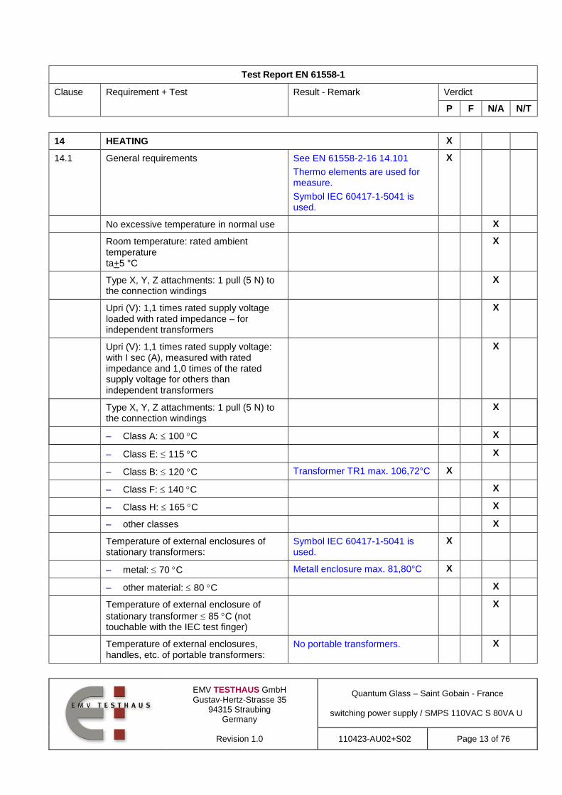
14 HEATING X
14.1 General requirements See EN 61558-2-16 14.101
Thermo elements are used for measure.
Symbol IEC 60417-1-5041 is used.
X
No excessive temperature in normal use X
Room temperature: rated ambient temperature ta+5 °C
X
Type X, Y, Z attachments: 1 pull (5 N) to the connection windings
X
Upri (V): 1,1 times rated supply voltage loaded with rated impedance – for independent transformers
X
Upri (V): 1,1 times rated supply voltage: with I sec (A), measured with rated impedance and 1,0 times of the rated supply voltage for others than independent transformers
X
Type X, Y, Z attachments: 1 pull (5 N) to the connection windings
X
– Class A: 100 C X
– Class E: 115 C X
– Class B: 120 C Transformer TR1 max. 106,72°C X
– Class F: 140 C X
– Class H: 165 C X
– other classes X
Temperature of external enclosures of stationary transformers:
Symbol IEC 60417-1-5041 is used.
X
– metal: 70 C Metall enclosure max. 81,80°C X
– other material: 80 C X
Temperature of external enclosure of
stationary transformer 85 C (not touchable with the IEC test finger)
X
Temperature of external enclosures, handles, etc. of portable transformers:
No portable transformers. X

EMV TESTHAUS GmbH
Gustav-Hertz-Strasse 35 94315 Straubing
Germany
Revision 1.0
Quantum Glass – Saint Gobain - France
switching power supply / SMPS 110VAC S 80VA U
110423-AU02+S02 Page 14 of 76
Test Report EN 61558-1
Clause Requirement + Test Result - Remark Verdict
P F N/A N/T
– continuously held parts of metal:
55 C
X
– continuously held parts of other
material: 75 C
X
– not continuously held parts of metal:
60 C
X
– not continuously held parts of other
material: 80 C
X
Temperature of terminals for external
conductors 70 C
X1, X2 max.:75,5°C X
Temperature of terminals of switches
70 C
X
Temperature of internal and external wiring:
Only PCB wiring. X
– rubber: 65 C X
– PVC: 70 C X
Temperature of parts where safety can be affected:
No such parts. X
– rubber: 75 C X
– phenol-formaldehyde: 105 C X
– urea-formaldehyde: 85 C X
– impregnated paper and fabric:
85 C
X
– impregnated wood: 85 C X
– PVC, polystyrene and similar
thermoplastic material: 65 C
X
– varnished cambric: 75 C X
Temperature rise of supports 85 C X
Temperature of printed boards: X
– bonded with phenol-formaldehyde:
105 C
X
– melamine-formaldehyde: 105 C X
– phenol-furfural: 105 C X
– bonded with epoxy: 140 C L301 max.: 108,19°C X
Electric strength between input and output windings (18.3, 1 min); test voltage (V) .................. :
4200V X

EMV TESTHAUS GmbH
Gustav-Hertz-Strasse 35 94315 Straubing
Germany
Revision 1.0
Quantum Glass – Saint Gobain - France
switching power supply / SMPS 110VAC S 80VA U
110423-AU02+S02 Page 15 of 76
Test Report EN 61558-1
Clause Requirement + Test Result - Remark Verdict
P F N/A N/T
14.2 Application of 14.1 or 14.3 according to the insulation system
X
14.2.1 Class of isolating system (classified materials according to IEC 60085 and IEC 60216)
Class B declared. X
14.2.2 No classified material, or system but the measured temperature does not exceed the value of Class A
X
14.2.3 No classified material or system but the measured temperature exceeds the value for Class A, the live parts of the transformers are submitted to the test of 14.3
X
14.3 Accelerated ageing test for undeclared class of isolating system
Class B declared by manufacturer.
X
Cycling test (10 cycles): X
– measuring of the no-load input current (mA)
X
14.3.1 – heat run (temperature in table 2) X
14.3.2 – vibration test: 30 min; amplitude 0,35 mm; frequency range: 10 Hz, 55 Hz, 10 Hz
X
14.3.3 – moisture treatment (48 h, 17.2) X
14.3.4 Measurements and tests at the beginning and after each test:
X
– deviation of the no-load input current, measured at the beginning of the test
is 30%
X
– insulation resistance acc. cl.18.1 and 18.2
X
– electric strength, no breakdown (18.3); 2 min; test voltage 35% of specified value (table VI)
X
– Transformers (50 or 60 Hz version) are tested after the dielectric strength test as follows: under no load; duration: 5 min; Upri(V):1,2 times rated supply voltage; frequency (Hz): 2 times rated frequency
X
EMV TESTHAUS GmbH
Gustav-Hertz-Strasse 35 94315 Straubing
Germany
Revision 1.0
Quantum Glass – Saint Gobain - France
switching power supply / SMPS 110VAC S 80VA U
110423-AU02+S02 Page 16 of 76
Test Report EN 61558-1
Clause Requirement + Test Result - Remark Verdict
P F N/A N/T
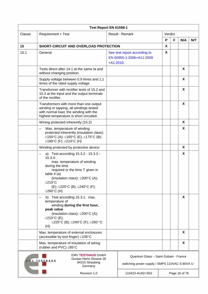
15 SHORT-CIRCUIT AND OVERLOAD PROTECTION X
15.1 General See test report according to
EN 60950-1:2006+A11:2009
+A1:2010.
X
Tests direct after 14.1 at the same ta and without changing position.
X
Supply voltage between 0,9 times and 1,1 times of the rated supply voltage
X
Transformer with rectifier tests of 15.2 and 15.3 at the input and the output terminals of the rectifier.
X
Transformers with more than one output winding or tapping, all windings tested with normal load, the winding with the highest temperature is short circuited.
X
Wining protected inherently (15.2) X
– Max. temperature of winding protected inherently (insulation class):
150C (A); 165C (E); 175C (B);
190C (F); 210C (H)
X
Winding protected by protective device: X
– a) Test according 15.3.2 - 15.3.3 – 15.3.4: max. temperature of winding during the time required or the time T given in table 4 (a)
(insulation class): 200C (A);
215C
(E); 225C (B); 240C (F);
260C (H)
X
– b) Test according 15.3.1: max. temperature of winding during the first hour, peak value
(insulation class): 200C (A);
215C (E);
225C (B); 240C (F); 260 C (H)
X
Max. temperature of external enclosures
(accessible by test finger) 105C
X
Max. temperature of insulation of wiring
(rubber and PVC) 85C
X
EMV TESTHAUS GmbH
Gustav-Hertz-Strasse 35 94315 Straubing
Germany
Revision 1.0
Quantum Glass – Saint Gobain - France
switching power supply / SMPS 110VAC S 80VA U
110423-AU02+S02 Page 17 of 76
Test Report EN 61558-1
Clause Requirement + Test Result - Remark Verdict
P F N/A N/T
Temperature rise of supports 105C X
15.2 For inherently short-circuit proof transformers and for transformers with rectifiers test by short circuit of the output winding at rated supply voltage x 1,1:
temperature rises values in table 3
X
15.3 For non-inherently short-circuit proof transformers and for transformers with
rectifiers: temperature rises values in table 3
X
15.3.1 Output terminals short-circuited: protection device operates, test at 0,9 … 1,1 of the rated supply voltage
X
15.3.2 If protected by a fuse accordance with either IEC 60269-2 or IEC 60269-3, or a technical equivalent fuse, the transformer is loaded as in table 4.
X
15.3.3 If protected by a fuse accordance with either
IEC 60127 or ISO 8820, or a technical equivalent fuse, the transformer is loaded with the current as specified for the longest precarcing time.
If protected by a miniature fuses in accordance to IEC 60127, 1,5 times of the rated fuse, until steady state condition (in addition)
X
15.3.4 If protected by a circuit-breaker according to IEC 60898 the transformer is loaded with a current equal to 1,45 times the value of the circuit-breaker rated current
X
15.3.5 If other overload protection than a fuse (IEC 60127) or a circuit-breaker (IEC60 898) test with 0,95 times of operating current
X
If an internal week point is used, the test must be repeated with two new samples. The two additional samples works similar to the first sample.
Temperatures in the limit of table 3
X
15.4 For non-short-circuit proof transformers:
temperature rises values in table 3, tests as indicated in 15.3
X

EMV TESTHAUS GmbH
Gustav-Hertz-Strasse 35 94315 Straubing
Germany
Revision 1.0
Quantum Glass – Saint Gobain - France
switching power supply / SMPS 110VAC S 80VA U
110423-AU02+S02 Page 18 of 76
Test Report EN 61558-1
Clause Requirement + Test Result - Remark Verdict
P F N/A N/T
15.5 For fail-safe transformers: X
15.5.1 Three additional new specimens are used X
– Upri (V): 1,1 times rated supply voltage .............................................................. :
X
– Isec (A): 1,5 times rated output current .............................................................. :
X
– time until steady-state conditions t1 (h) ..................................................................... :
X
– time until failure t2 (h): t1; 5 h .................... : X
15.5.2 During the test: X
– no flames, molten material, etc. X
– temperature of enclosure 175 C X
– temperature of plywood support
125 C
X
After the test: X
– electric strength (Cl. 18, 1 min, test voltage: 35% of specified value); no flashover or break- down for primary-to-secondary only for safety isolating, isolating and separating transformer and for primary-to-body for all kinds of transformer
X
– bare hazardous live parts not accessible by test finger through holes of enclosure
X
16 MECHANICAL STRENGTH X
16.1 General X
After tests of 16.2, 16.3 and 16.4 X
– no damage X
– hazardous live parts not accessible by test pin according to 9.2
X
– no damage for insulating barriers X
– handles, levers, etc. have not moved on shafts
No handles, levers, etc. X
16.2 Transformers (stationary and portable s. 16.1)
X
EMV TESTHAUS GmbH
Gustav-Hertz-Strasse 35 94315 Straubing
Germany
Revision 1.0
Quantum Glass – Saint Gobain - France
switching power supply / SMPS 110VAC S 80VA U
110423-AU02+S02 Page 19 of 76
Test Report EN 61558-1
Clause Requirement + Test Result - Remark Verdict
P F N/A N/T
For stationary and portable transformers: 3blows, impact energy 0,5Nm
Tested with 0,5Nm.
No hazard or damage of parts inside the enclosure after the test. Slight damage of enclosure.
X
16.3 Portable transformers (except of plug in transformers)
No portable transformers. X
For portable transformers: 100 falls, 25 mm
X
16.4 Transformers with integrated pins (plug in transformers), the following tests are carried out:
No such transformers. X
a) plug-in transformers: tumbling barrel
test: 50 x 250 g; 25 x 250 g
X
b) torque test of the plug pins with 0,4 Nm
X
c) pull force according to table 5 for each pin
X
17 PROTECTION AGAINST HARMFUL INGRESS OF WATER AND MOISTURE
X
17.1 Degree of protection (IP code marked on the transformer)
IP20 X
Test according to 17.1.1 and for other IP ratings test according to IEC 60 529:
X
– stable operating temperature before starting the test for < IPX8
X
– transformer mounted and wired as in normal use
X
– fixed transformer mounted as in normal use by the tests according to 17.1.1 A to J
X
– portable transformers placed in the most unfavourable position and wired as in normal use
No portable transformers. X
– glands tightened with a torque equal to two-thirds of 25.6
X
After the tests: X
– dielectric strength test according to 18.3
X
Inspection: X

EMV TESTHAUS GmbH
Gustav-Hertz-Strasse 35 94315 Straubing
Germany
Revision 1.0
Quantum Glass – Saint Gobain - France
switching power supply / SMPS 110VAC S 80VA U
110423-AU02+S02 Page 20 of 76
Test Report EN 61558-1
Clause Requirement + Test Result - Remark Verdict
P F N/A N/T
a) in dust-proof transformers no deposit of talcum powder
X
b) no deposit of talcum powder inside dust-tight transformers
X
c) no trace of water on live parts except SELV parts below 15 V ac or 25 V dc or insulation if hazard for the user or surroundings no reduction of creepage distances
X
d) no accumulation of water in
transformers IPX1 so as to impair safety
X
e) no trace of water entered in any part of water-tight transformer
X
f) no entry into the transformer by the relevant test probe
No entry into the transformer. X
17.1.1 Tests on transformers with enclosure: X
A) Solid-object-proof transformers: X
– 2 IP2X test finger (IEC 60 529) and test pin (fig. 3)
Tested with testfinger and test pin.
X
B) Solid-object-proof transformers: X
– wire 2,5 mm; force 3 N X
– IP4X, wire 1 mm; force 1 N X
C) Dust-proof transformers, IP5X; dust chamber according to IEC 60 529, fig. 2:
X
a) transformer has operating temperature
X
b) transformer, still operating, is placed in the dust chamber
X
c) the door of the dust chamber is closed
X
d) fan/blower is switched on X
e) after 1 min transformer is switched off for cooling time of 3 h
X
D) Dust-tight transformers (IP6X) test according to C)
X
E) Drip-proof transformers (IPX1) test according to fig. 3 of IEC 60 529 for 10 min
X

EMV TESTHAUS GmbH
Gustav-Hertz-Strasse 35 94315 Straubing
Germany
Revision 1.0
Quantum Glass – Saint Gobain - France
switching power supply / SMPS 110VAC S 80VA U
110423-AU02+S02 Page 21 of 76
Test Report EN 61558-1
Clause Requirement + Test Result - Remark Verdict
P F N/A N/T
F) Rain-proof transformers (IPX2) test according to fig. 3 of IEC 60 529 for 10 min in operation, any angle up to 15°
X
G) Spray proofed transformers (IPX3) test according to fig. 4 of IEC 60 529 for 10 min in operation and 10 min switched off , time for complete oscillation (2 x 120°) is 4 sec.
X
H) Splash-proof transformers (IPX4) test according to fig. 4 of IEC 60 529 (see F) for 10 min in operation and 10 min switched off (the tube shall oscillate
360 )
X
I) Jet-proof transformer (IPX5) test according to fig. 6 of IEC 60 529 (nozzle 6,3mm)
X
J) Powerful Jet-proof transformer (IPX6) test according to fig. 6 of IEC 60 529 (nozzle 12 mm)
X
K) Watertight transformers (IPX7) X
L) Pressure watertight transformers (IPX8)
X
17.2 After moisture test (48 h for IP20, 168 h for other transformers):
No hazard and damage during and after the test.
X
– insulation resistance and electric strength (Cl. 18)
See clause 18. X
18 INSULATION RESISTANCE AND ELECTRIC STRENGTH X
18.2 Insulation resistance between: X
– live parts and body for basic
insulation 2 M
48MΩ X
– live parts and body for reinforced
insulation 7 M
X
– input circuits and output circuits for
basic insulation 2 M
X
– input circuits and output circuits for
double or reinforced insulation 5 M
50MΩ X
– each input circuit and all other input
circuits connected together 2 M
X

EMV TESTHAUS GmbH
Gustav-Hertz-Strasse 35 94315 Straubing
Germany
Revision 1.0
Quantum Glass – Saint Gobain - France
switching power supply / SMPS 110VAC S 80VA U
110423-AU02+S02 Page 22 of 76
Test Report EN 61558-1
Clause Requirement + Test Result - Remark Verdict
P F N/A N/T
– each output circuit and all other output circuits connected together
2 M
X
– hazardous live parts and metal parts with basic insulation (Class II
transformers) 2 M
X
– body and metal parts with basic insulation (Class II transformers)
5 M
X
– metal foil in contact with inner and
outer surfaces of enclosures 2 M
X
18.3 Electric strength test (1 min): no flashover or breakdown:
X
1) basic insulation between input circuits and output circuits; working voltage (V); test voltage (V) ........................................... :
X
2) double or reinforced insulation between input circuits and output circuits; working voltage (V); test voltage (V) ........................................................ :
4200V X
3) basic or supplementary insulation between:
X
a) live parts of different polarity; working voltage (V); test voltage (V) ............................................................... :
X
b) live parts and the body if intended to be connected to protective earth ........................................................... :
2100V X
c) inlet bushings and cord guards and anchorages .......................................... :
X
d) live parts and an intermediate conductive part ........................................... :
X
e) intermediate conductive parts and body ............................................................ :
X
4) Reinforced insulation between the body and live parts; working voltage (V); test voltage (V) ........................................... :
X
18.4 Upri (V): 2 times rated input voltage; no load; frequency (Hz): 2 times rated frequency; duration (min): 5 min ............................. :
See IEC 61558-2-16 18.4. X
No breakdown between: X

EMV TESTHAUS GmbH
Gustav-Hertz-Strasse 35 94315 Straubing
Germany
Revision 1.0
Quantum Glass – Saint Gobain - France
switching power supply / SMPS 110VAC S 80VA U
110423-AU02+S02 Page 23 of 76
Test Report EN 61558-1
Clause Requirement + Test Result - Remark Verdict
P F N/A N/T
– turns of winding X
– input and output windings X
– adjacent input or output windings X
– windings and iron core X
18.5 Touch current and protective earth current X
18.5.1 Touch current
Touch current measured after the clause 14 test (hot) for class I and class II transformers (class II transformers with metal foil at the plastic surface). The test circuit according figure 8. Measuring network according Figure J1 (Annex J). If the frequency is >30kHz, measuring across the 500 Ohm resistor of J1 (burn effects).
X
Measurement of the touch current with switch p of picture 8 in both positions and in combination with switches e and n. The measured values are less than the required values of table 8b.
X
– switches n and e in on position Max.: 0,1mA X
– switch n: off and switch e: on Max.: 0,1mA X
– switch n: on and switch e: off Max.: 1,7mA X
18.5.2 Protective earth conductor current X
The transformer is connected as in clause 14
Impedance of the ammeter < 0,5 Ohm, connected between earth terminal of the transformer and protective earth conductor
Max.:3,5mA X
The measured values are less than the required values of table 8b.
0,1mA X
19 CONSTRUCTION
19.1 See also IEC 61558-2-4 and IEC 61558-2-16
Input and output circuits electrically separated (IEC 61558-2-X
Double insulation between primary and secondary circuit.
X
No possibility of any connection between these circuits (IEC 61558-2-X)
X

EMV TESTHAUS GmbH
Gustav-Hertz-Strasse 35 94315 Straubing
Germany
Revision 1.0
Quantum Glass – Saint Gobain - France
switching power supply / SMPS 110VAC S 80VA U
110423-AU02+S02 Page 24 of 76
Test Report EN 61558-1
Clause Requirement + Test Result - Remark Verdict
P F N/A N/T
19.1.1 The insulation between input and output winding(s) consist of double or reinforced insulation (exception see 19.1.3) (IEC61558-2-X)
Double insulation between primary and secondary circuit.
X
Class I transformers (IEC 61558-2-X) X
Insulation between input windings and body consist of basic insulation (IEC 61558-2-X)
Basic insulation between input windings and body.
X
Insulation between output windings and body consist of basic insulation (IEC 61558-2-X)
Basic insulation between output windings and body.
X
Class II transformers (IEC 61558-2-X) X
Insulation between input windings and body con-sist of double or reinforced insulation (IEC 61558-2-X)
X
Insulation between output windings and body consist of double or reinforced insulation (IEC 61558-2-X)
X
19.2 Fiercely burning material not used No such materials. X
Unimpregnated cotton, silk, paper and fibrous material not used as insulation
X
Wax-impregnated, etc. not used X
19.3 Portable transformer: short-circuit proof or fail-safe
Stationary transformers. X
19.4 Class II transformers: contact between accessible metal parts and conduits or metal sheaths of supply wiring impossible
Cass I transformers. X
19.5 Class II transformers: part of supplementary or reinforced insulation, during reassembly after routine servicing not omitted
Cass I transformers. X
19.6 Class I and II transformers: creepage distances and clearances over supplementary or reinforced insulation if wire, screw, nut, etc. become loose or fall
out of position not 50% specified values (Cl. 26)
Considered.
Lock washers are used.
X
19.7 Conductive parts connected to accessible metal parts by resistors or capacitors shall be separated from hazardous live parts by double or reinforced insulation
X

EMV TESTHAUS GmbH
Gustav-Hertz-Strasse 35 94315 Straubing
Germany
Revision 1.0
Quantum Glass – Saint Gobain - France
switching power supply / SMPS 110VAC S 80VA U
110423-AU02+S02 Page 25 of 76
Test Report EN 61558-1
Clause Requirement + Test Result - Remark Verdict
P F N/A N/T
19.8 Resistors or capacitors connected between hazardous live parts and the body (accessible metal parts) consist of:
Double insulation by C215 and C216 (Y2).
X
– components according to IEC 60065, 14.1 or capacitor Y1 according to IEC 60384-14
Capacitors are used. X
– at least two separate components X
– if one component is short-circuited or opened, values specified in Cl. 9 shall not be exceeded
X
– if the working voltage is < 250 V, one Y1 capacitor according 60384-14 is allowed
X
19.9 Insulation material input/output and supplementary insulation of rubber resistant to ageing
Considered. X
Creepage distances (if cracks) specified values (Cl. 26)
X
19.10 Protection against accidental contact by insulating coating:
Metal enclosure is used. X
a) ageing test (section I, IEC 60 068-2-2),
test Ba: 168 h; 70 C
X
b) impact test (spring-operated impact hammer according to IEC 60068-2-63; 0,5 ± 0,05 J)
X
c) scratch test (hardened steel pin) electric strength test according to Cl. 18
X
19.11 Handles, levers, knobs, etc.: No such parts. X
– insulating material X
– supplementary insulation covering X
– separated from shafts or fixing by supplementary insulation
X
19.12 Windings construction X
19.12.1 Undue displacement in all types of transformers not allowed:
X
– of input or output windings or turns thereof
Considered. X

EMV TESTHAUS GmbH
Gustav-Hertz-Strasse 35 94315 Straubing
Germany
Revision 1.0
Quantum Glass – Saint Gobain - France
switching power supply / SMPS 110VAC S 80VA U
110423-AU02+S02 Page 26 of 76
Test Report EN 61558-1
Clause Requirement + Test Result - Remark Verdict
P F N/A N/T
– of internal wiring or wires for external connection
Considered. X
– of parts of windings or of internal wiring in case of rupture or loosening
Considered. X
19.12.2 Serrated tape: Insulated windings wires used.
Serrated tape used for basic insulation (See 19.12.3). Three layers are used.
X
– distance through insulation according to table 13
No requirements to thickness of insulation.
X
– one additional layer of serrated tape, and
X
– one additional layer without serration X
– in case of cheekless bobbins the end turns of each layer shall be prevented from being displaced
X
19.12.3 Insulated windings wires: X
– to all types of transformers for basic or supplementary insulation taken separately
X
a) Winding wire with basic or supplementary insulation:
Double insulation by insulated windings wires.
X
– comply with Annex K X
– the insulation of the conductor: two layers
X
b) Winding wire with double or reinforced insulation:
Double insulation by insulated windings wires.
X
– comply with Annex K Comply with Annex C and U
EN 60950-1
X
– the insulation of the insulated winding wire: three layers
Three layers used. X
– dielectric strength test with the values according 18.3 multiplied by 1,25
Tested with 4900V X
Where the wire is wound: X
– upon metal or ferrite cores X
– upon enamelled wire X
– under enamelled wire X

EMV TESTHAUS GmbH
Gustav-Hertz-Strasse 35 94315 Straubing
Germany
Revision 1.0
Quantum Glass – Saint Gobain - France
switching power supply / SMPS 110VAC S 80VA U
110423-AU02+S02 Page 27 of 76
Test Report EN 61558-1
Clause Requirement + Test Result - Remark Verdict
P F N/A N/T
An additional insulation with a dti of supplementary insulation provided between insulated an enamelled wires
Adhedsive tape used. No requirements to thickness of insulation material.
CMC 10260 and CMC10262 tape used.Tapes are UL approved.
X
100 % Routine test according to Annex K.3 for windings giving double or reinforced insulation
100% Routine test must be performed by the manufacturer.
X
For windings providing reinforced insulation the values in table 13, table C.1 and table D1, box 2) c), are not required
Double insulation by three layer winding insulation. Only basic insulation is needed.
X
19.13 Handles, operating levers and the like shall be fixed
No such parts. X
19.14 Protection against electric shock: covers securely fixed, 2 independent fixing means, one with tool
Considered. X
19.15 Transformer with pins for fixed socket-outlets: no strain on socket-outlet
No such transformer. X
Additional torque 0,25 Nm X
19.16 Protection index for portable transformers: No portable transformers. X
200 VA IP20 and instructions for use X
> 200 VA 2,5 kVA IPX4 (single-phase) X
> 200 VA 6,3 kVA IPX4 (polyphase) X
> 2,5 VA (single-phase) IP21 X
> 6,3 VA (polyphase) IP21 X
19.17 Transformers IPX1 - IPX6 totally enclosed, except for drain hole (diameter
5 mm or 20 mm² with width 3 mm); drain hole not required for transformer completely filled with insulating materials
No such transformer. X
19.18 Transformers IPX1 with a moulded, if any
No such transformer. X
19.19 Class I transformers with a non-detachable flexible cable or cord with earth conductor and a plug with earth contact
No power supply cord. X
19.20 Live parts of SELV and PELV-circuits: separation not less than PRI/SEC of a safety isolating transformer
No SELV or PELV circuits. X

EMV TESTHAUS GmbH
Gustav-Hertz-Strasse 35 94315 Straubing
Germany
Revision 1.0
Quantum Glass – Saint Gobain - France
switching power supply / SMPS 110VAC S 80VA U
110423-AU02+S02 Page 28 of 76
Test Report EN 61558-1
Clause Requirement + Test Result - Remark Verdict
P F N/A N/T
– SELV output circuits separated by double or reinforced insulation from all other than SELV or PELV circuits
X
– SELV output circuits separated by basic insulation from other SELV or PELV circuits
X
19.20.1 SELV circuits and parts not connected to protective earth, to live parts, or protective conductors forming part of other circuits
X
Nominal voltage (V) > 25 V a.c. or 60 V d.c., the required insulation fulfils the high voltage test according to table 8 a
X
19.20.2 PELV-circuits double or reinforced insulation is necessary
X
19.21 FELV-circuits: protection against contact fulfils the min. test voltage required for the primary circuit
No FELV circuits. X
19.22 Class II transformers shall not be provided with means for protective earth
Class I equipment. X
For fixed transformers an earth conductor with double or reinforced insulation to accessible metal parts is allowed
X
19.23 Class III transformers shall not be provided with means for protective earth
Class I equipment. X
20 COMPONENTS X
Components such as switches, plugs, fuses, lamp holders, flexible cables and cords, comply with relevant IEC standard
X
Components inside the transformer pass all tests of this standard together with the transformer tests
X
Testing of components separately to the transformer according the relevant standard:
X
– Ratings of the component in line with the transformer ratings, including inrush current. Component test according the component standard, based on the component marking (rating).
X

EMV TESTHAUS GmbH
Gustav-Hertz-Strasse 35 94315 Straubing
Germany
Revision 1.0
Quantum Glass – Saint Gobain - France
switching power supply / SMPS 110VAC S 80VA U
110423-AU02+S02 Page 29 of 76
Test Report EN 61558-1
Clause Requirement + Test Result - Remark Verdict
P F N/A N/T
– Components without markings tested under transformer conditions including inrush current.
No components without markings.
X
– If no IEC standard exist, the component is tested under transformer conditions.
All components have IEC standart.
X
20.1 Appliance couplers for main supply shall comply with:
No power supply cords or appliance couplers.
X
– IEC 60320 for IPX0 X
– IEC 60309 for other X
20.2 Automatic controls shall comply with IEC 60730-1
No automatic controls. X
20.3 Thermal-links comply with IEC 60691 No thermal-links. X
20.4 Switches shall comply with annex F No switches. X
Disconnection from the supply: X
– by a switch, disconnecting all poles of the supply (full disconnection under the relevant overvoltage category
X
– or a flexible supply cable and cord with plug
X
– or an instruction sheet: disconnection by all-poles switches incorporated in fixed wiring
. X
20.5 Socket-outlets of the output circuit shall be such that there is no unsafe compatibility to plugs complying with input circuit.
No socket-outlets. X
Plugs and socket-outlets for SELV systems with both a rated current ≤ 3A and a rated voltage ≤24 V shall comply with following:
X
SELV plug and socket-outlets shall comply with IEC 60 884-2-4 and IEC 60 906-3
X
– It is not possible for plugs to enter socket-outlets of other standardised voltage system
X
– Socket outlets do not accommodate plugs of other standardised voltage systems
X

EMV TESTHAUS GmbH
Gustav-Hertz-Strasse 35 94315 Straubing
Germany
Revision 1.0
Quantum Glass – Saint Gobain - France
switching power supply / SMPS 110VAC S 80VA U
110423-AU02+S02 Page 30 of 76
Test Report EN 61558-1
Clause Requirement + Test Result - Remark Verdict
P F N/A N/T
– Socket outlets do not have a protective earth contact
X
PELV plug and socket-outlets shall comply with following:
X
– It is not possible for plugs to enter socket-outlets of other standardised voltage system
X
– Socket outlets do not accommodate plugs of other standardised voltage systems
X
– Socket outlets do not have a protective earth contact
X
FELV plug and socket-outlets shall comply with following:
X
– It is not possible for plugs to enter socket-outlets of other standardised voltage system
X
– Socket outlets do not accommodate plugs of other standardised voltage systems
X
20.6 Thermal cut-outs, overload releases etc. have adequate breaking capacity
X
– Thermal cut outs fulfil the relevant requirements of 20.7 and 20.8
Thermik P06 used, 250V.
– Thermal links fulfil the relevant requirements of 20.8
No thermal links. X
– The breaking capacity is in accordance with the relevant fuse standard
Littlefuse 021501.6MXP is used
250V.
X
20.6.1 For Fuses According IEC 60127 and IEC 60269, the fuse current does not exceed 1,1 times of the rated value
Considered. X
20.7 Thermal cut outs shall meet the requirements of 20.7.1.1 and 20.7.2, or 20.7.1.2 and 20.7.2.
Considered. X
20.7.1 Requirements according to IEC 60730-1 Thermal cut is aproved by IEC60730-1 and IEC 60730-2-9
See 20.7.1.1 and 20.7.2
X
20.7.1.1 Thermal cut-out tested as component shall comply with IEC 60730-1
X

EMV TESTHAUS GmbH
Gustav-Hertz-Strasse 35 94315 Straubing
Germany
Revision 1.0
Quantum Glass – Saint Gobain - France
switching power supply / SMPS 110VAC S 80VA U
110423-AU02+S02 Page 31 of 76
Test Report EN 61558-1
Clause Requirement + Test Result - Remark Verdict
P F N/A N/T
a) Thermal cut outs type 1 or type 2 (IEC 60730-1)
Considered. X
b) Thermal cut outs fulfil the requirements of micro-interruption (type 1C or 2 C) or micro-disconnection, (type 1B or 2B) (see IEC 60730-1)
Considered. X
c) Thermal cut outs with manual rest have a trip free mechanism (type 1E and 2E) (see IEC 60730-1)
No thermal cut outs with manual reset.
X
d) The number of cycles of automatic action shall be:
X
– 3000 cycles for self resetting thermal cut-outs
Up to 10000 switching cycles. X
– 300 cycles for non self resetting thermal cut-outs resetting by hand
No self resetting thermal cut-outs.
X
– 300 cycles for non self resetting thermal cut-outs resetting disconnecting
No self resetting thermal cut-outs.
X
– 30 cycles for non self resetting thermal cut-outs which are only resettable by a tool
No self resetting thermal cut-outs.
X
e) Thermal cut outs fulfil the electrical stress according IEC 60730-1, 6.14.2
Approved by IEC 60730-1. X
f) Characteristic of thermal cut-outs: X
– ratings according IEC 60730-1, cl. 5
250VAC, 10A X
– classification according to: X
1) nature of supply to IEC 60730-1, cl. 6.1
Up to 500VAC, 100VDC. X
2) type of load controlled to IEC 60730-1, cl. 6.2
10 A cosφ =1, 6,3A cosφ = 0,6 X
3) degree of protection IPX0 to IEC 60730-1, cl. 6.5.1
IP20 X
4) degree of protection IP0X to IEC 60730-1, cl. 6.5.2
IP20 X
5) pollution degree to IEC 60730-1, cl. 6.5.3
PD II X
EMV TESTHAUS GmbH
Gustav-Hertz-Strasse 35 94315 Straubing
Germany
Revision 1.0
Quantum Glass – Saint Gobain - France
switching power supply / SMPS 110VAC S 80VA U
110423-AU02+S02 Page 32 of 76
Test Report EN 61558-1
Clause Requirement + Test Result - Remark Verdict
P F N/A N/T
6) comparative tracking index to IEC 60730-1, cl. 6.13
225, Insulating group IIIa. X
7) max. ambient temperature to IEC 60730-1, cl. 6.7
Max.: 180°C
Switching temperature 90°C.
X
20.7.1.2 Thermal cut-out tested as a part of the transformer, test with 3 samples:
X
– at least micro-interruption or micro-disconnection (IEC 60730-1)
X
– 300 h aged at ta (transformer) + 10°C X
– subjected to a number of cycles for automatic operating according 20.7.1.1
X
During the test no sustaining arcing shall occur, during and after the test no damage at the thermal cut out and the transformer in the sense of this standard
X
20.7.2 Thermal cut-outs shall have adequate breaking capacity
X
20.7.2.1 The output of the transformer with a non self resetting thermal cut out is short circuited at a supply voltage 1, 1 of rated supply voltage. After opening of the cut off, the supply voltage is switched of, until the transformer is cooling down.
No transformer with non self resetting thermal cut outs.
X
– 3 cycles at 25° C for transformers without ta min
X
– 3 cycles at ta min for transformers with ta min
X
– after the 3 cycles short circuit of the output at 1,1 of rated supply voltage for 48 h.
X
During the tests no sustaining arcing shall occur After the test: withstand the test of clause 18, show no damage in sense of this standard, and be operational.
X
20.7.2.2 The output of the transformer with a self resetting thermal cut out is short circuited at a supply voltage 1, 1 of rated supply voltage.
Transformer switching of after < 5sec.
X
– 48 h at 25° C for transformers without ta min
X

EMV TESTHAUS GmbH
Gustav-Hertz-Strasse 35 94315 Straubing
Germany
Revision 1.0
Quantum Glass – Saint Gobain - France
switching power supply / SMPS 110VAC S 80VA U
110423-AU02+S02 Page 33 of 76
Test Report EN 61558-1
Clause Requirement + Test Result - Remark Verdict
P F N/A N/T
– 24 h at ta and 24 h at ta min for transformers with ta min
Tamin: 0°C X
During the tests no sustaining arcing shall occur After the test: withstand the test of clause 18, show no damage in sense of this standard, and be operational.
Considered. X
20.7.3 Test of a PTC resistor: No PTC resistors. X
5 cycles: transformer short-circuited for 48 h by 1,1 times of the input voltage and max. ta
X
5 cycles: transformer short-circuited for 48 h by 0,9 times of the input voltage and min. ta (if declared)
X
After the test: withstand the test of clause 18, show no damage in sense of this standard, and be operational.
X
20.8 Thermal links shall be tested in one of the following two ways.
No thermal links. X
20.8.1 Thermal-links shall comply with IEC 60 691 as a separate component.
X
– electrical conditions to IEC 60691, cl. 6.1
X
– thermal conditions to IEC 60691, cl. 6.2
X
– ratings to IEC 60691, cl. 8 b X
– suitability of sealing components, impregnating fluids or cleaning solvents IEC 60691, cl. 8 c
X
20.8.2 Thermal-links tested as a part of the transformer:
No thermal links. X
– ageing test 300 h by 35 C or
ta + 10 C
X
– After transformer fault condition the thermal link operate without sustaining arcing
X
– after opening the thermal-link shall have an insulation resistance of at
least 0,2 M
X
– 3 cycles for replaceable thermal-links X
– 3 new specimens for not replaceable thermal-links
X

EMV TESTHAUS GmbH
Gustav-Hertz-Strasse 35 94315 Straubing
Germany
Revision 1.0
Quantum Glass – Saint Gobain - France
switching power supply / SMPS 110VAC S 80VA U
110423-AU02+S02 Page 34 of 76
Test Report EN 61558-1
Clause Requirement + Test Result - Remark Verdict
P F N/A N/T
20.9 Self-resetting devices not used if mechanical, electrical, etc. hazards
No mechanical, electrical, etc. hazard.
X
20.10 Thermal cut-outs which can be reset by soldering operation are not allowed
No thermal cut-outs which can be reset by soldering operation.
X
20.11 Overload protection devices do not operate during test (20 times switched on and off, at no load); Upri (V): 1,1 times rated supply voltage.
Considered. X
21 INTERNAL WIRING X
21.1 Internal wiring and electrical connections protected or enclosed
PCB wiring. X
Wire-ways smooth and free from sharp edges
X
21.2 Openings in sheet metal: edges rounded
(radius 1,5 mm) or bushings of insulating material
X
21.3 Bare conductors: distances adequately maintained
X
21.4 When external wires are connected to terminal, internal wiring shall not work loose
X
21.5 Insulation of heat-resistant and non-hygroscopic material for insulated conductors subject to temperature rise > limiting values given in 14.1
X
22 SUPPLY CONNECTION AND EXTERNAL FLEXIBLE CABLES AND CORDS
X
22.1 All cables, flexible cords etc. shall have appropriate current and voltage ratings
Wago clamps / 24A, 320V. X
22.2 Input and output wiring inlet and outlet openings for external wiring: separate entries without damage to protective covering of cable or cord
Separate entries for input and output wiring.
X
Input and output wiring inlet and outlet openings for flexible cables or cords: insulating material or bushing of insulating material
X
Bushings for external wiring: reliably fixed, not of rubber unless part of cord guard
No bushings. X

EMV TESTHAUS GmbH
Gustav-Hertz-Strasse 35 94315 Straubing
Germany
Revision 1.0
Quantum Glass – Saint Gobain - France
switching power supply / SMPS 110VAC S 80VA U
110423-AU02+S02 Page 35 of 76
Test Report EN 61558-1
Clause Requirement + Test Result - Remark Verdict
P F N/A N/T
22.3 Fixed transformer: X
– possible to connect after fixing X
– inside space for wires allow easy introduction and connection of conductors
X
– fitting of cover without damage to conductors
X
– contact between insulation of external supply wires and live parts of different polarity not allowed
X
22.4 Length of power supply cord for portable transformers between 2 m and 4 m; without 0,5 mm
2
No portable transformers. X
22.5 Power supply cords for transformers IPX0 and transformers “for indoor use only” > IPX0:
No power supply cords. X
– for transformers with a mass < 3 kg: 60227 IEC52 ( H03VV-..) (60245 IEC 53)
X
– for transformers with a mass > 3 kg: 60227 IEC53 (H05VV-..) or 60245 IEC 53
X
Power supply cords for transformers for outdoor use: > IPX0: 60245 IEC57 (H05RN-..)
X
22.6 Power supply cords for single-phase portable transformers with input current
16A:
No portable transformers. X
– cord set fitted with an appliance coupler in accordance with IEC 60320
X
22.7 Nominal cross-sectional area (mm²); input current (A) at rated output not less than shown in table 9
No power supply cords. X
22.8 Class I transformer with power supply flexible cable: green/yellow core connected to earth terminal
No power supply cords. X
Plug for single-phase transformer with
input current at rated output 16 A according to IEC 60 083, IEC 60 906-1 or IEC 60 309
X
22.9 Type X, Y or Z attachments: see relevant part 2
Type X used. X

EMV TESTHAUS GmbH
Gustav-Hertz-Strasse 35 94315 Straubing
Germany
Revision 1.0
Quantum Glass – Saint Gobain - France
switching power supply / SMPS 110VAC S 80VA U
110423-AU02+S02 Page 36 of 76
Test Report EN 61558-1
Clause Requirement + Test Result - Remark Verdict
P F N/A N/T
22.9.1 For type Z attachment: moulding enclosure and power supply cable do not affect insulation of cable
X
22.9.2 Inlet openings or inlet bushing: without risk of damage to protective covering of power supply cord
X
Insulation between conductor and enclosure:
X
– for Class I transformer: insulation of conductor plus separate basic insulation
Min.: Basic insulation by insulation of wiring.
X
– for Class II transformer: insulation of conductor plus double or reinforced insulation
X
22.9.3 Inlet bushings: No inlet bushings. X
– no damage to power supply cord X
– reliably fixed X
– not removable without tool X
– not integral with power supply cord (for type X attachment)
X
– not of natural rubber except for Class I transformer with type X, Y and Z attachments
X
22.9.4 For portable transformers which are moved while operating:
No such transformers. X
– cord guards, if any, of insulating material and fixed
X
Compliance is tested by the oscillating test according to fig. 7:
X
– loaded force during the test according to fig. 7
X
– 10 N for a cross-sectional area > 0,75 X
– 5 N for a cross-sectional area 0,75 X
After the test according to fig. 7: X
– no short-circuit between the conductors
X
– no breakage of more than 10% of stands of any conductor
X
EMV TESTHAUS GmbH
Gustav-Hertz-Strasse 35 94315 Straubing
Germany
Revision 1.0
Quantum Glass – Saint Gobain - France
switching power supply / SMPS 110VAC S 80VA U
110423-AU02+S02 Page 37 of 76
Test Report EN 61558-1
Clause Requirement + Test Result - Remark Verdict
P F N/A N/T
– no separation of the conductor from the terminal
X
– no loosening of any cord guards X
– no damage of the cord or cord guard X
– no broken strands piercing the insulation and not becoming accessible
X
22.9.5 Cord anchorages for type X attachment: X
– glands in portable transformers not used unless possibility for clamping all types and sizes of cable
Considered. X
– moulded-on designs, tying the cable into a knot and tying the end with string not allowed
No such methode. X
– labyrinths, if clearly how, permitted No labyrinths. X
– replacement of cable easily possible Considered. X
– protection against strain and twisting clearly how
Considered. X
– suitable for different types of cable unless only one type of cable for transformer
Considered. X
– the entire flexible cable or cord with covering can be mounted into the cord anchorage
Considered. X
– if tightened or loosened no damage Considered. X
– no contact between cable or cord and accessible or electrically connected clamping screws
Considered. X
– cord clamped by metal screw not allowed
No cord clamped by metal screw. X
Cord anchorages for type X, Y, Z attachments: cores of power external flexible cable or cord insulated from accessible metal parts by:
X
– basic insulation (Class I transformers), separate insulating barrier/cord anchorage
Insulating by outer insulation of power cord.
X
– supplementary insulation (Class II transformers), special lining/cable or cord sheath of cable sheath of cable
Class I equipment. X

EMV TESTHAUS GmbH
Gustav-Hertz-Strasse 35 94315 Straubing
Germany
Revision 1.0
Quantum Glass – Saint Gobain - France
switching power supply / SMPS 110VAC S 80VA U
110423-AU02+S02 Page 38 of 76
Test Report EN 61558-1
Clause Requirement + Test Result - Remark Verdict
P F N/A N/T
Cord anchorages for type X and Y attachments:
Considered. X
– replacement of external flexible cable or cord does not impair compliance with standard
Considered. X
– the entire flexible cable or cord with covering can be mounted into the cord anchorage
Considered X
– if tightened or loosened no damage Considered. X
– no contact between cable or cord and accessible or electrically connected clamping screws
Considered. X
Tests for type X with special cords, type Y, type Z
No power supply cords attached,
Fixed connection to mains.
X
Test for type X attachments one test with a cord with smallest and one test with a cord with the largest cross-sectional area:
X
– for the test with clamping screws or tightened with torque 2/3 of that specified in table 11
X
– not possible to push cable into transformer
X
– 25 pulls of 1 s X
– 1 min torque according to table 10 X
– mass (kg); pull (N); torque (Nm) ...................... : X
– during test: cable not damaged X
– after test: longitudinal displacement
2 mm for cable or cord and 1 mm for conductors in terminals
X
– creepage distances and clearances values specified in Cl. 26
X
22.9.6 Space for external cords or cable for fixed wiring and for type X and Y attachments:
X
– before fitting cover, possibility to check correct connection and position of conductors
Cover can’t be installed if power supply cord is already installed.
X
– cover fitted without damage to supply cords
X
EMV TESTHAUS GmbH
Gustav-Hertz-Strasse 35 94315 Straubing
Germany
Revision 1.0
Quantum Glass – Saint Gobain - France
switching power supply / SMPS 110VAC S 80VA U
110423-AU02+S02 Page 39 of 76
Test Report EN 61558-1
Clause Requirement + Test Result - Remark Verdict
P F N/A N/T
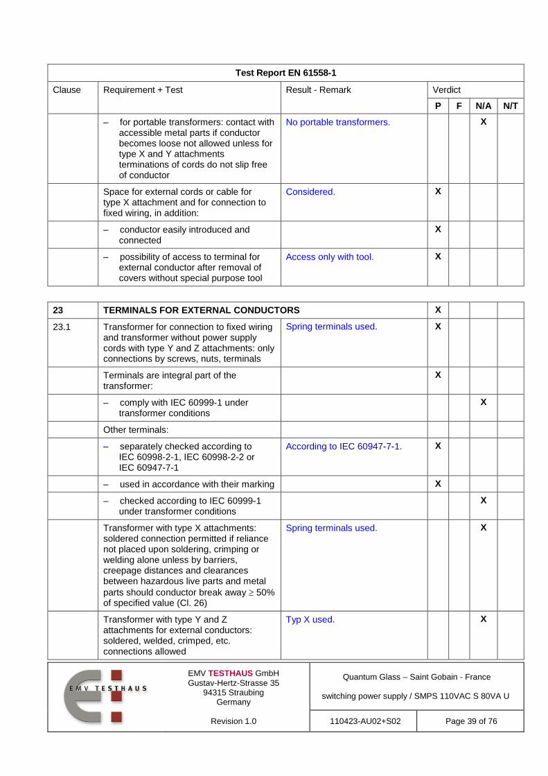
– for portable transformers: contact with accessible metal parts if conductor becomes loose not allowed unless for type X and Y attachments terminations of cords do not slip free of conductor
No portable transformers. X
Space for external cords or cable for type X attachment and for connection to fixed wiring, in addition:
Considered. X
– conductor easily introduced and connected
X
– possibility of access to terminal for external conductor after removal of covers without special purpose tool
Access only with tool. X
23 TERMINALS FOR EXTERNAL CONDUCTORS X
23.1 Transformer for connection to fixed wiring and transformer without power supply cords with type Y and Z attachments: only connections by screws, nuts, terminals
Spring terminals used. X
Terminals are integral part of the transformer:
X
– comply with IEC 60999-1 under transformer conditions
X
Other terminals:
– separately checked according to IEC 60998-2-1, IEC 60998-2-2 or IEC 60947-7-1
According to IEC 60947-7-1. X
– used in accordance with their marking X
– checked according to IEC 60999-1 under transformer conditions
X
Transformer with type X attachments: soldered connection permitted if reliance not placed upon soldering, crimping or welding alone unless by barriers, creepage distances and clearances between hazardous live parts and metal
parts should conductor break away 50% of specified value (Cl. 26)
Spring terminals used. X
Transformer with type Y and Z attachments for external conductors: soldered, welded, crimped, etc. connections allowed
Typ X used. X

EMV TESTHAUS GmbH
Gustav-Hertz-Strasse 35 94315 Straubing
Germany
Revision 1.0
Quantum Glass – Saint Gobain - France
switching power supply / SMPS 110VAC S 80VA U
110423-AU02+S02 Page 40 of 76
Test Report EN 61558-1
Clause Requirement + Test Result - Remark Verdict
P F N/A N/T
For Class II transformer: reliance not placed upon soldering, crimping or welding alone unless by barriers, creepage distances and clearances between hazardous live parts and metal
parts should conductor break away 50% of specified value (Cl. 26)
Class I equipment used. X
23.2 Terminals for type X with special cords Y and Z attachments shall be suitable for their purpose:
X
– test by inspection according to 23.1 and 23.2
Considered. X
– pull of 5 N to the connection before test according to 14.1
No damage after test. X
23.3 Other terminals than Y and Z attachments shall be so fixed that when the clamping means is tightened or loosened:
X
– terminal does not work loose Considered. X
– internal wiring is not subjected to stress
X
– creepage distances and clearance are not reduced below the values specified in Cl. 26
Considered. X
23.4 Other terminals than Y and Z attachments shall be so designed that:
X
– they clamp the conductor between metallic surfaces with sufficient contact pressure
Spring clamps used. X
– without damage to the conductor No damageafter test. X
– test by inspection according to 23.3 and 23.4
X
– 10 times fastening and loosening a conductor with the largest cross-sectional area with 2/3 of the torque specified in Cl. 25
2,5mm2 cross section used, no
damage.
X
23.5 Terminals for fixed wiring and for type X: located near their associated terminals of different polarities and the earth terminal if any
Considered. X
23.6 Terminal blocks not accessible without the aid of a tool
Transformer is for building in, have to be considered in the end product.
X

EMV TESTHAUS GmbH
Gustav-Hertz-Strasse 35 94315 Straubing
Germany
Revision 1.0
Quantum Glass – Saint Gobain - France
switching power supply / SMPS 110VAC S 80VA U
110423-AU02+S02 Page 41 of 76
Test Report EN 61558-1
Clause Requirement + Test Result - Remark Verdict
P F N/A N/T
23.7 Transformer with type X attachments: stranded conductor test (8 mm removed):
See instuction manual, only solid wires or crimped litz wires are allowed to use.
X
– Class I transformers: no connection between live parts and accessible metal parts
X
– free wire of earth terminal: no touching of live parts
No connection between free wire of earth terminal and live parts.
X
– Class II transformers: no connection between live parts and accessible metal parts, no connection between live parts and metal parts separated from accessible metal parts by supplementary insulation
Class I equipment. X
23.8 Terminals for a current > 25 A: No current > 25A. X
– pressure plate, or X
– two clamping screws X
23.9 When terminal, other than protective earth conductor, screws loosened as far as possible, no contact:
Considered. X
– between terminal screws and accessible metal parts
X
– between terminal screws and inaccessible metal parts for Class II transformers
Class I equipment. X
24 PROVISION FOR PROTECTIVE EARTHING X
24.1 Class I transformers: accessible conductive parts connected to earth terminal
Considered. X
Class II transformers: no provision for earth
Class I equipment. X
24.2 Protective earth terminal for connection to fixed wiring and for type X attachment transformers: comply with Cl. 23, adequately locked, not possible to loosen without a tool
Transformer is for building in, have to be considered in the end product.
X
24.3 No risk of corrosion from contact between metal of earth terminal and other terminal
X
In case of earth terminal body of Al, no risk of corrosion from contact between Cu and Al
No Al case of earth terminal body used.
X

EMV TESTHAUS GmbH
Gustav-Hertz-Strasse 35 94315 Straubing
Germany
Revision 1.0
Quantum Glass – Saint Gobain - France
switching power supply / SMPS 110VAC S 80VA U
110423-AU02+S02 Page 42 of 76
Test Report EN 61558-1
Clause Requirement + Test Result - Remark Verdict
P F N/A N/T
Body of earth terminal or screws/nuts of brass or other metal resistant to corrosion
X
24.4 Resistance of connection between earth
terminal and metal parts 0,1 with a min. 25 A or 1,5 rated input current at 1 min
32A, 120s, 0,02 Ohm. X
24.5 Class I transformers with external flexible cables or cords:
Considered. X
– current-carrying conductors becoming touch before the earth conductor
X
25 SCREWS AND CONNECTIONS X
25.1 Screwed connections withstand mechanical stresses
X
Screws transmitting contact pressure or likely to be tightened by the user or having a diameter < 2,8 mm, shall screw into metal
Screw diameter > 2,8mm. X
Screws not of metal which is soft or liable to creep (Zn, Al)
No such screws. X
Screws of insulating material: not used for electrical connection
No such screws. X
Screws not of insulating material if their replacement by metal screws can impair supplementary or reinforced insulation
No such screws. X
Screws to be removed (replacement etc. of power supply cord) not of insulating material if their replacement by metal screws can impair basic insulation
No such screws. X
No damage after torque test: diameter (mm); torque (Nm); ten times
X
No damage after torque test: diameter (mm); torque (Nm); five times
3mm, 0,5Nm X
25.2 Screws in engagement with thread of insulating material:
No such screws. X
– length of engagement 3 mm + 1/2 screw diameter or 8 mm
X
– correct introduction into screw hole X
25.3 Electrical connections: contact pressure not transmitted through insulating material
No contact pressure transmittet through insulating material.
X

EMV TESTHAUS GmbH
Gustav-Hertz-Strasse 35 94315 Straubing
Germany
Revision 1.0
Quantum Glass – Saint Gobain - France
switching power supply / SMPS 110VAC S 80VA U
110423-AU02+S02 Page 43 of 76
Test Report EN 61558-1
Clause Requirement + Test Result - Remark Verdict
P F N/A N/T
25.4 In case of use of thread-forming (sheet metal) screws for connection of current-carrying parts: clamping and locking means provided
No such screws. X
Thread-cutting (self-tapping) screws used for the connection of current-carrying parts allowed if they generate a full form machine screw thread and if not operated by the user
X
Thread-cutting screws and thread-forming screws used for earth continuity allowed if at least 2 screws for each connection are used and it is not necessary to disturb the connection in normal use
X
25.5 Screws for current-carrying mechanical connections locked against loosening
Two screws are locked against loosening by bolt adhedsive
X
Rivets for current-carrying connections subject to torsion locked against loosening
No rivets. X
25.6 Test of screwed glands with a torque according table 12. After the test no damage at the transformer and the gland.
No such parts.. X
26 CREEPAGE DISTANCES AND CLEARANCES X
26.1 Specified values according to: Material goup IIIa assumed. X
– table 13, material group IIIa X
– table C, material group II X
– table D, material group I X
1. Insulation between input and output circuits (basic insulation):
X
a) measured values specified values (mm) ................................................ :
X
2. Insulation between input and output circuits (double or reinforced insulation):
Cl=5,5 Cr=6,0 bei 300V
Cl=5,0,Cr=5,4 bei 270V
Cl=4,5, Cr=4,8 bei 240V
X
a) measured values specified values (mm) ................................................ :
Cl=6,8, Cr=6,8>
Cl=4,5, Cr=4,8 bei 240V
Mainssec X3
X
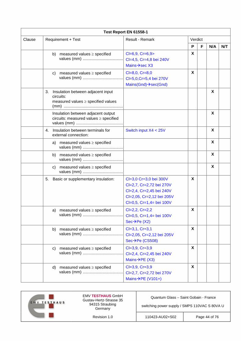
EMV TESTHAUS GmbH
Gustav-Hertz-Strasse 35 94315 Straubing
Germany
Revision 1.0
Quantum Glass – Saint Gobain - France
switching power supply / SMPS 110VAC S 80VA U
110423-AU02+S02 Page 44 of 76
Test Report EN 61558-1
Clause Requirement + Test Result - Remark Verdict
P F N/A N/T
b) measured values specified values (mm) ................................................ :
Cl=6,9, Cr=6,9>
Cl=4,5, Cr=4,8 bei 240V
Mainssec X3
X
c) measured values specified values (mm) ................................................ :
Cl=8,0, Cr=8,0
Cl=5,0,Cr=5,4 bei 270V
Mains(Gnd)sec(Gnd)
X
3. Insulation between adjacent input circuits:
measured values specified values (mm) ................................................................. :
X
Insulation between adjacent output
circuits: measured values specified values (mm) ...................................................... :
X
4. Insulation between terminals for external connection:
Switch input X4 < 25V X
a) measured values specified values (mm) ................................................ :
X
b) measured values specified values (mm) ................................................ :
X
c) measured values specified values (mm) ................................................ :
X
5. Basic or supplementary insulation: Cl=3,0 Cr=3,0 bei 300V
Cl=2,7, Cr=2,72 bei 270V
Cl=2,4, Cr=2,45 bei 240V
Cl=2,05, Cr=2,12 bei 205V
Cl=0,5, Cr=1,4= bei 100V
X
a) measured values specified values (mm) ................................................ :
Cl=2,2, Cr=2,2
Cl=0,5, Cr=1,4= bei 100V
SecPe (X2)
X
b) measured values specified values (mm) ................................................ :
Cl=3,1, Cr=3,1
Cl=2,05, Cr=2,12 bei 205V
SecPe (CS508)
X
c) measured values specified values (mm) ................................................ :
Cl=3,9, Cr=3,9
Cl=2,4, Cr=2,45 bei 240V
MainsPE (X3)
X
d) measured values specified values (mm) ................................................ :
Cl=3,9, Cr=3,9
Cl=2,7, Cr=2,72 bei 270V
MainsPE (V101+)
X

EMV TESTHAUS GmbH
Gustav-Hertz-Strasse 35 94315 Straubing
Germany
Revision 1.0
Quantum Glass – Saint Gobain - France
switching power supply / SMPS 110VAC S 80VA U
110423-AU02+S02 Page 45 of 76
Test Report EN 61558-1
Clause Requirement + Test Result - Remark Verdict
P F N/A N/T
6. Reinforced or double insulation:
measured values specified values (mm) ................................................................. :
X
7. Distance through insulation: X
a) measured values specified values (mm) ................................................ :
Basic insulation by insulating foil.
No thickness required.
X
Creepage distances and clearances are measured:
X
– for fixed wiring and type X attachments with max. and min. size
X
– for type X with a special cord, Y or Z attachments with the supply cable as delivered
No mains supply cord appended.
X
– for layers of serrated tapes the values are so determined as if the serration coincided through the different layers
No such tapes used. X
– for printed wiring shall be used the unreduced values for live parts as in table 13, C.1 or D.1, except if printed wiring complies with IEC 60 664-3
X
If the pollution generates high and persistent conductivity caused:
PD II X
– clearances of P3 increased with min. 1,6 mm
X
– value X in Annex A increased with 4,0 mm
X
26.2 Creepage distances (cr) and clearances (cr)
X
26.2.1 Windings covered with adhesive tape Windings covered with IEC 60454 approved tape.
X
– the values of pollution degree 1 are fulfilled
No reduced values. X
– all isolating material are classified acc. to IEC 60085 and IEC 60216
X
– test A of 26.2.3 is fulfilled X
26.2.2 Uncemented insulating parts pollution degree P2 or P3
No such parts. X
– all isolating material are classified acc. to IEC 60085 and IEC 60216
X

EMV TESTHAUS GmbH
Gustav-Hertz-Strasse 35 94315 Straubing
Germany
Revision 1.0
Quantum Glass – Saint Gobain - France
switching power supply / SMPS 110VAC S 80VA U
110423-AU02+S02 Page 46 of 76
Test Report EN 61558-1
Clause Requirement + Test Result - Remark Verdict
P F N/A N/T
– values of pollution degree 1 are not applicable
X
26.2.3 Cemented insulating parts No cemented insulating parts. X
– all isolating materials are classified acc. to IEC 60085 and IEC 60216
X
– values of distance through insulation (dti) are fulfilled
X
– creepage distances and clearances are not required
X
– test A of this sub clause is fulfilled X
Test A X
– thermal class X
– working voltage X
– Test with three specially specimens, with uninsinuated wires, without impregnation or potting
X
Two of the three specimens are subjected to:
X
– the relevant humidity treatment according to 17.2 (48 h)
X
– the relevant dielectric strength test of 18.3 multiplied with factor 1,35
X
– One of the three specimens is subjected to the relevant dielectric strength test of 18.3 multiplied by the factor 1,35 immediately at the end of the last cycle with high temperature
X
Impulse dielectric test according to
4.1.1.2.1 of IEC 60 664-1 (1,2 / 50 s waveform) – see Annex R of IEC 61558-1
X
26.2.4 Enclosed parts, by impregnation or potting
No such parts. X
26.2.4.1 – The requirements of reduced values as stated for pollution degree 1 (P1) are fulfilled
X
– all isolating materials are classified acc. to IEC 60085 and IEC 60216
X
Test B X

EMV TESTHAUS GmbH
Gustav-Hertz-Strasse 35 94315 Straubing
Germany
Revision 1.0
Quantum Glass – Saint Gobain - France
switching power supply / SMPS 110VAC S 80VA U
110423-AU02+S02 Page 47 of 76
Test Report EN 61558-1
Clause Requirement + Test Result - Remark Verdict
P F N/A N/T
– thermal class X
– working voltage X
– Test with three specially specimens, potted or impregnated. The dielectric strength test is applied directly to the joint.
X
Two of the three specimens are subjected to:
X
– the relevant humidity treatment according to 17.2 (48 h)
X
– the relevant dielectric strength test of 18.3 multiplied with factor 1,25
X
– One of the three specimens is subjected to the relevant dielectric strength test of 18.3 multiplied by the factor 1,25 immediately at the end of the last cycle with high temperature
X
The three spacemen pass the Impulse dielectric test according to 4.1.1.2.1 of
IEC 60 664-1 (1,2 / 50 s waveform) – see Annex R of IEC 61558-1
X
26.2.4.2 – The requirements of distance through insulation (dti) are fulfilled. (P1 values are not required)
X
– all isolating materials are classified acc. to IEC 60085 and IEC 60216
X
Test C X
– thermal class X
– working voltage X
– Test with three specimens, potted or impregnated. (finished components)
X
– Neither cracks, nor voids in the insulating compounds
X
Two of the three specimens are subjected to:
X
– the relevant humidity treatment according to 17.2 (48 h)
X
– the relevant dielectric strength test of 18.3 multiplied with factor 1,35
X

EMV TESTHAUS GmbH
Gustav-Hertz-Strasse 35 94315 Straubing
Germany
Revision 1.0
Quantum Glass – Saint Gobain - France
switching power supply / SMPS 110VAC S 80VA U
110423-AU02+S02 Page 48 of 76
Test Report EN 61558-1
Clause Requirement + Test Result - Remark Verdict
P F N/A N/T
– One of the three specimens is subjected to the relevant dielectric strength test of 18.3 multiplied by the factor 1,35 immediately at the end of the last cycle with high temperature
X
The three spacemen pass the Impulse dielectric test according to 4.1.1.2.1 of
IEC 60 664-1 (1,2 / 50 s waveform) – see Annex R of IEC 61558-1
X
26.3 Distance through insulation Basic insulation is adequate, no requirements to thickness of insulation. Basic insulation between insulated winding wire and other winding wire or core.
X
For double or reinforced insulation, the required values of Tables 13, C1, and D1 – boxes 2b, 2c and 7 are fulfilled
X
The insulation fulfil the material classification according IEC 60085 or 60216 or the test of 14.3
X
26.3.1 Reduced values of the thickness of insulation for supplementary or reinforced insulation are allowed if the following conditions are fulfilled:
Basic insulation is adequate, no requirements to thickness of insulation. Basic insulation between insulated winding wire and other winding wire or core.
X
– the isolating materials are classified acc. to IEC 60085 and IEC 60216
X
– the test of 14.3 is fulfilled X
– If both requirements are fulfilled, the required values for solid insulation can be multiplied by 0,4
X
– Minimum thickness of reinforced insulation >0,2 mm
X
– Minimum thickness of supplementary insulation >0,1 mm
X
26.3.2 Insulation in thin sheet form Basic insulation is adequate, no requirements to thickness of insulation. Basic insulation between insulated winding wire and other winding wire or core.
X
– If the layers are non separable (glued together):
X

EMV TESTHAUS GmbH
Gustav-Hertz-Strasse 35 94315 Straubing
Germany
Revision 1.0
Quantum Glass – Saint Gobain - France
switching power supply / SMPS 110VAC S 80VA U
110423-AU02+S02 Page 49 of 76
Test Report EN 61558-1
Clause Requirement + Test Result - Remark Verdict
P F N/A N/T
– The requirement of 3 layers is fulfilled
X
– The mandrel test according 26.3.3 is fulfilled with 150 N
X
– The required values for d.t.i. of Tables 13, C.1 and D.1 – marked by index “e” are fulfilled.
X
– If the layers are separated: X
– The requirement of 2 layers is fulfilled
X
– If serrated tape is used, 1 additional layer (serrated) and one additional layer without serration is required
X
– The mandrel test according 26.3.3 is fulfilled on each layer with 50 N
* X
– The required values for d.t.i. of Tables 13, C.1 and D.1 – marked by index “e” are fulfilled.
X
– If the layers are separated (alternative:
X
– The requirement of 3 layers is fulfilled
X
– If serrated tape is used, 1 additional layer (serrated) and one additional layer without serration is required
X
– The mandrel test according 26.3.3 is fulfilled on 2/3 of the layers with 100 N
X
– The required values for d.t.i. of Tables 13, C.1 and D.1 – marked by index “e” are fulfilled.
X
Test according to 14.3 and if the isolating materials are classified acc. to IEC 60085 and IEC 60216 no distances through insulation are required for insulation in thin sheet form
X
The figures within square brackets in box 2 and 7 of table 13 (C.1/D.1) are used for insulation in thin sheet form as follows:
X

EMV TESTHAUS GmbH
Gustav-Hertz-Strasse 35 94315 Straubing
Germany
Revision 1.0
Quantum Glass – Saint Gobain - France
switching power supply / SMPS 110VAC S 80VA U
110423-AU02+S02 Page 50 of 76
Test Report EN 61558-1
Clause Requirement + Test Result - Remark Verdict
P F N/A N/T
– rated output > 100 VA values in square brackets apply
X
– rated output 25 VA 100 VA 2/3 of the value in square brackets apply
X
– rated output 25 VA 1/3 of the value in square brackets apply
X
26.3.3 Mandrel test of insulation in thin sheet form (specimen 0f 70 mm width are necessary):
No tests performed. Basic insulation is adequate, no requirements to thickness of insulation. Basic insultion between insulated winding wire and other winding wire or core.
X
– If the layers are non separable – at least 3 layers glued together fulfil the test:
X
– pull force of 150 N X
– high voltage test of 5,0 kV or the test voltage of 18.3 multiplied by 1,25 whatever is the greater. No flashover, no breakdown.
X
– If the layers are separable and 2/3 of at least 3 layers fulfil the test.
X
– pull force of 100 N X
– high voltage test of 5,0 kV or the test voltage of 18.3 multiplied by 1,25 whatever is the greater. No flashover, no breakdowns.
X
– If the layers are separable 1 of at least 2 layers fulfil the test:
X
– pull force of 50 N X
– high voltage test of 5,0 kV or the test voltage of 18.3 multiplied by 1,25 whatever is the greater. No flashover, no breakdown.
X
27 RESISTANCE TO HEAT, FIRE AND TRACKING X
27.1 Resistance to heat X
All insulating parts are resistant to heat Class of insulation min. Class B X
For parts of rubber, which passed the test of 19.9, no additional test is required.
No parts of rubber. X
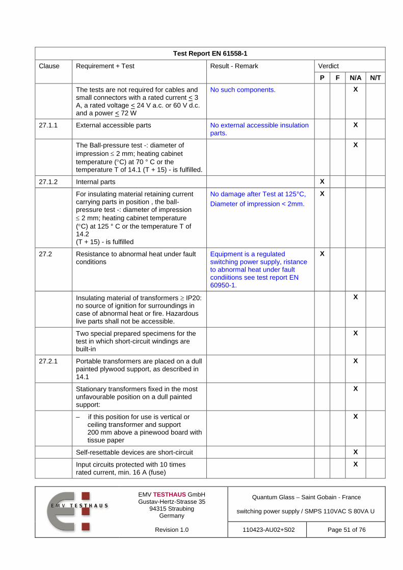
EMV TESTHAUS GmbH
Gustav-Hertz-Strasse 35 94315 Straubing
Germany
Revision 1.0
Quantum Glass – Saint Gobain - France
switching power supply / SMPS 110VAC S 80VA U
110423-AU02+S02 Page 51 of 76
Test Report EN 61558-1
Clause Requirement + Test Result - Remark Verdict
P F N/A N/T
The tests are not required for cables and small connectors with a rated current < 3 A, a rated voltage < 24 V a.c. or 60 V d.c. and a power < 72 W
No such components. X
27.1.1 External accessible parts No external accessible insulation parts.
X
The Ball-pressure test -: diameter of
impression 2 mm; heating cabinet
temperature (C) at 70 ° C or the temperature T of 14.1 (T + 15) - is fulfilled.
X
27.1.2 Internal parts X
For insulating material retaining current carrying parts in position , the ball-pressure test -: diameter of impression
2 mm; heating cabinet temperature
(C) at 125 ° C or the temperature T of 14.2 (T + 15) - is fulfilled
No damage after Test at 125°C,
Diameter of impression < 2mm.
X
27.2 Resistance to abnormal heat under fault conditions
Equipment is a regulated switching power supply, ristance to abnormal heat under fault condiitions see test report EN 60950-1.
X
Insulating material of transformers IP20: no source of ignition for surroundings in case of abnormal heat or fire. Hazardous live parts shall not be accessible.
X
Two special prepared specimens for the test in which short-circuit windings are built-in
X
27.2.1 Portable transformers are placed on a dull painted plywood support, as described in 14.1
X
Stationary transformers fixed in the most unfavourable position on a dull painted support:
X
– if this position for use is vertical or ceiling transformer and support 200 mm above a pinewood board with tissue paper
X
Self-resettable devices are short-circuit X
Input circuits protected with 10 times rated current, min. 16 A (fuse)
X

EMV TESTHAUS GmbH
Gustav-Hertz-Strasse 35 94315 Straubing
Germany
Revision 1.0
Quantum Glass – Saint Gobain - France
switching power supply / SMPS 110VAC S 80VA U
110423-AU02+S02 Page 52 of 76
Test Report EN 61558-1
Clause Requirement + Test Result - Remark Verdict
P F N/A N/T
Test time for protective devices of the transformer without load:
X
– max. 15 days, or X
– definitive interruption in the input circuit
X
If non-self-resettable or replaceable protective devices are used the following cycle test is necessary:
X
– non-self-resettable: 30 cycles with no load until interruption and 2 h cool down
X
– replaceable protective device: 10 cycles with no load until interruption and 2 h cool down
X
During the tests: X
– no flames occur X
– support temperature shall not exceed
125 C
X
– no ignition of the tissue paper X
27.2.2 After the tests: X
a) transformer with definitive interruption in the input circuit withstands the test with 35% of the values according to table 8a
X
b) transformer with no definitive interruption withstands the test voltage (100%) according to table 8a of Cl. 18: hazardous live parts are not touchable by the stranded test finger
X
27.3 Resistance to fire X
All isolating parts of the transformer shall be resistant to ignition and spread of fire. The test according to IEC 60695-2-10 is required
Relevant components are V-0 UL94.
X
27.3.1 External accessible parts (glow wire tests) Relevant components are V-0 UL94.
X
– 650° C for enclosures X
– 650 ° C for parts retaining current carrying parts in position and terminals for external conductors Current < 0,2 A
X

EMV TESTHAUS GmbH
Gustav-Hertz-Strasse 35 94315 Straubing
Germany
Revision 1.0
Quantum Glass – Saint Gobain - France
switching power supply / SMPS 110VAC S 80VA U
110423-AU02+S02 Page 53 of 76
Test Report EN 61558-1
Clause Requirement + Test Result - Remark Verdict
P F N/A N/T
– 750° C for parts retaining current carrying parts in position and terminals for external conductors with fixed wiring. Current > 0,2 A
X
– 850° C for parts retaining current carrying parts in position and terminals for external conductors with non fixed wiring. Current > 0,2 A
X
27.3.2 Internal parts Relevant components are V-0 UL94.
X
– 550° C for internal insulating material – not retaining current carrying parts in position
X
– 650° C for coil formers (bobbins) X
– 650 ° C for parts retaining current carrying parts in position and terminals for external conductors. Current < 0,2 A
X
– 750° C for parts retaining current carrying parts in position and terminals for external conductors with fixed wiring. Current > 0,2 A
X
– 850° C for parts retaining current carrying parts in position and terminals for external conductors with non fixed wiring. Current > 0,2 A
X
27.4 For IP other than IPX0:If insulating parts retaining current carrying parts in position and under P3 conditions, the material resistance to tracking is at least material of group IIIa
Considered. X
Test (175 V): no flashover or breakdown before 50 drops
X
28 RESISTANCE TO RUSTING X
Ferrous parts protected against rusting Considered. X
E ANNEX E , GLOW WIRE TEST X
The test is required according to IEC 60695-2-10 and IEC 60695-2-11 with the following additions:
X

EMV TESTHAUS GmbH
Gustav-Hertz-Strasse 35 94315 Straubing
Germany
Revision 1.0
Quantum Glass – Saint Gobain - France
switching power supply / SMPS 110VAC S 80VA U
110423-AU02+S02 Page 54 of 76
Test Report EN 61558-1
Clause Requirement + Test Result - Remark Verdict
P F N/A N/T
E.1 Clause 6, “Severities” of IEC 6095-2-11, apply with the temperature stated in 27.3 of IEC 61558-1
X
E2 Clause 8, “Conditioning”, of IEC 60695-2-11 apply, preconditioning is required
X
E3 Clause 10, “Test Procedure”, of IEC 60695-2-11apply, The tip of the glow wire is applied to the flat side of the surface.
X
F ANNEX F, REQUIREMENTS FOR MANUALLY OPERATED SWITCHES WHICH ARE PARTS OF THE TRANSFORMER
X
F.2 Manually operated mechanical switches, tested as separate component, shall comply with IEC 61058 under the conditions of F2.
No such switches. X
F.§ Manually operated mechanical switches tested as part of the transformer shall comply with the conditions specified under F.3
X
H ANNEX H, ELECTRONIC CIRCUITS (IEC 61558-1) X
H1 General notes on tests (addition to clause 5)
X
H.2 SHORT-CIRCUIT AND OVERLOAD PROTECTION (ADDITION TO CLAUSE 15)
X
H..2.1 Circuits designed and applied so that fault conditions do not render the appliance unsafe
X
During and after each test: X
– temperatures do not exceed values specified in table 3 of Cl. 15.1
Considered X
– transformer complies with conditions specified in sub-clause 15.1
X
If a conductor of a pcb becomes open circuited, the transformer is considered to have withstood the particular test, provided that all six conditions as specified are met
No open circuit on PCB. X
H.2.2 Fault conditions a) to f) of sub-clause H.2.3 are not tested if the following conditions are met:
X

EMV TESTHAUS GmbH
Gustav-Hertz-Strasse 35 94315 Straubing
Germany
Revision 1.0
Quantum Glass – Saint Gobain - France
switching power supply / SMPS 110VAC S 80VA U
110423-AU02+S02 Page 55 of 76
Test Report EN 61558-1
Clause Requirement + Test Result - Remark Verdict
P F N/A N/T
– electronic circuit is a low-power circuit as specified
X
– safety of the appliance as specified does not rely on correct functioning of the electronic circuit
X
H.2.3 Fault conditions tested as specified when relevant:
For detailed fault condition tests, see test report according to EN 60950-1 (no. 110423-AU02+S01)
X
a) short-circuit of creepage distances and clearances, if less than specified in Cl. 26
X
b) open circuit at the terminals of any component
X
c) short-circuit of capacitors, unless they comply with IEC 60 384-14
X
d) short-circuit of any two terminals of an electronic component as specified
X
e) any failure of an integrated circuit as specified
X
f) low-power circuit: low-power points are connected to the supply source
X
Cl. 15 is repeated with a simulated fault as indicated in a) to e), if the transformer incorporates an electronic circuit to ensure compliance with Cl. 15
Considered. X
Fault condition e) is applied for encapsulated and similar components
Considered. X
PTC's and NTC's are not short-circuited if they are used as specified
Not short circuited. X
H.2.4 If for a fuse-link complying with IEC 60 127-3 rated fuse current I1 is used, current I2 is measured as specified:
Requirements were considered in the fault condtion tests in test report according to EN 60950-1 (no. 110423-AU02+S01)
X
– if I2 < 2,1 x I1 test of 15.8 is repeated with fuse-link short-circuited
X
– if I2 > 2,75 x I1, no other tests are necessary
X
If I2 > 2,1 x I1 and I2 < 2,75 x I1 test of 15.8 is repeated as specified
X
For fuses other than those complying with IEC 60 127-3, the test is carried out as specified 15.3.2 to 15.3.5
X

EMV TESTHAUS GmbH
Gustav-Hertz-Strasse 35 94315 Straubing
Germany
Revision 1.0
Quantum Glass – Saint Gobain - France
switching power supply / SMPS 110VAC S 80VA U
110423-AU02+S02 Page 56 of 76
Test Report EN 61558-1
Clause Requirement + Test Result - Remark Verdict
P F N/A N/T
H.3 CREEPAGE DISTANCES, CLEARANCES AND DISTANCES THROUGH INSULATION
X
H.3.1 For live parts separated by basic insulation smaller cr and cl as in 26 are allowed, if H2 is fulfilled.
X
In optocouplers no requirements of cr and cl
Approved optocouplers used. X
For coatings annex W applies. Smaller distances as required in IEC 60664-3, clause 4 are applicable,
No such PCB. X
For potted transformers cycling tests acc, 26.2. are applicable
No such transformer. X
H.3.2 The ma. surface temperature of optocouplers is 50 K
Approved optocouplers used. X
K ANNEX K, INSULATED WINDING WIRES FOR USE AS MULTIPLE LAYER INSULATION
X
Insulating winding wires approved by EN 60950-1 Annex U X
K.1 Wire construction: X
– insulated winding wire with min. two layers for basic or supplementary insulation
X
– insulated winding wire with min. three layers for reinforced insulation
X
– winding insulation material ............................... : X
K.2 Conformance test X
K.2.1 Test 13 of IEC 60 851-5 nominal conductor diameter
0,018 mm 0,1 mm, test as specified in 4.2.1 and 4.2.2 of IEC 60 851-5
X
Nominal conductor diameter > 0,1 mm,
2,5 mm, test as specified in 4.3.1 and 4.3.2 of IEC 60 851-5
X
Nominal conductor diameter < 2,5 mm, test as specified in 4.4.1 and 4.4.2 of IEC 60 851-5
X
High voltage test immediately after the above specified tests:
X

EMV TESTHAUS GmbH
Gustav-Hertz-Strasse 35 94315 Straubing
Germany
Revision 1.0
Quantum Glass – Saint Gobain - France
switching power supply / SMPS 110VAC S 80VA U
110423-AU02+S02 Page 57 of 76
Test Report EN 61558-1
Clause Requirement + Test Result - Remark Verdict
P F N/A N/T
– test voltage for two layers 3 kV X
– test voltage for three layers 5,5 kV X
K.2.2 Adherence and flexibility, test as specified under 5.1.4 of IEC 60 851-3
X
– high voltage test immediately after this test
X
– test voltage for two layers 3 kV X
– test voltage for three layers 5,5 kV X
K.2.3 Heat shock, test as specified under 3.1 or 3.2 of IEC 60 851-6:
X
– high voltage test immediately after this test
X
– test voltage for two layers 3 kV X
– test voltage for three layers 5,5 kV X
K.2.4 Retention of dielectric strength after bending, test as specified under test 13 of 4.6.1 c) of IEC 60 851-5
X
1. high voltage test immediately after this test
X
2. test voltage for two layers 3 kV X
3. test voltage for three layers 5,5 kV X
K.2.5 Resistance to abrasion, test 11 of IEC 60851-3
X
L Annex L – routine test X
Routine test must be done by the manufacturer. X
U Annex U – informative – Optional tw – marking for transformers
X
The tests of Annex U are based on constant S = 4500. Other constants are possible, if the test of U.5.2 is done with positive result.
X
U1 General notes and tests X
8 transformers of one type are necessary for the test. Tests according U5.
X

EMV TESTHAUS GmbH
Gustav-Hertz-Strasse 35 94315 Straubing
Germany
Revision 1.0
Quantum Glass – Saint Gobain - France
switching power supply / SMPS 110VAC S 80VA U
110423-AU02+S02 Page 58 of 76
Test Report EN 61558-1
Clause Requirement + Test Result - Remark Verdict
P F N/A N/T
U.2 Heating (addition to clause 14) X
14.4 Thermal endurance test X
Test according U5 and measurements according 11.1
X
Transformers tested as a integral part of the equipment (option), assigned with tw
X
The thermal conditions are so adjusted, that the duration of test is as indicated by the manufacturer.
X
If no indications are given, the test period is 30 days
X
After the test, when the transformers have returned to room temperature, they fulfil the following requirements:
X
a) The output voltage has not changed from the measured value at the beginning by more than allowed value of clause 11.1
X
b) The insulation resistance between input and output winding and between windings and body is, measured with 500 V d.c. , not less than 1 MOhm
X
c) The transformer fulfil the dielectric strength test with 35% of the values in Clause 18, Table 8.a.
X
The test result is positive, is min. 6 of the 7 samples have passed the test.
X
The test result is negative, if 2 or more samples fail the test
X
If the result is negative, the test can be repeated with 7 new samples
X
U.3 Short circuit and overload protection (addition to clause 15)
X
At short circuit and overload tests the winding temperature if less than the required value of table U.1
X
U.5 General requirements and information about thermal endurance test on windings
X
U.5.1 Thermal endurance test X
Transformers tested at rated output X

EMV TESTHAUS GmbH
Gustav-Hertz-Strasse 35 94315 Straubing
Germany
Revision 1.0
Quantum Glass – Saint Gobain - France
switching power supply / SMPS 110VAC S 80VA U
110423-AU02+S02 Page 59 of 76
Test Report EN 61558-1
Clause Requirement + Test Result - Remark Verdict
P F N/A N/T
Loads outside of the oven X
7 transformers are placed in the oven X
The temperature of the hottest winding of each of the 7 transformers is-together with the oven temperature, at the applicable temperature of table U.2
X
After 4 hours measuring of the actual winding temperatures. Regulation of the oven temperature if necessary
X
After 24 hours again measuring of the winding temperature. The temperatures of the 7 samples are very near to the required temperature of the values of table U.2. The test time of the coldest winding is not longer than twice the theoretical test time based on table U.2
X
U.5.2 The use of constant S other than 4500 in tw tests
X
U.5.2.1 Procedure a) X
The manufacturer prepares test results with a minimum of samples of 30.
X
T and log L are calculated from the dates X
The diagram according to Figure U.2 will be founded.
X
U.5.2.3 Procedure b) X
The testing authority shall test 14 new transformers
X
Test 1, based on clause U.5.1 but at the calculated test room temperature for 10 days. The test is continued until all transformer fail.
X
Calculation of the mean life L2 at temperature T2 according to U4
X
Test 2, based on clause U.5.1 but at a calculated room temperature T2 (for 120 days).The test time with T2 exceeds L2.
X
If all transformers fail before L2, the result is negative.
X
V ANNEX V, SYMBOLS TO BE USED FOR THERMAL CUT-OUTS X

EMV TESTHAUS GmbH
Gustav-Hertz-Strasse 35 94315 Straubing
Germany
Revision 1.0
Quantum Glass – Saint Gobain - France
switching power supply / SMPS 110VAC S 80VA U
110423-AU02+S02 Page 60 of 76
Test Report EN 61558-1
Clause Requirement + Test Result - Remark Verdict
P F N/A N/T
V.2.1.1 Restored by manual operation
IEC 489/98
X
V.2.1.2 Restored by disconnection of the supply
IEC 490/98
X
V.2.1.3 Thermal link
IEC 491/98
X
V.2.2 Self-resetting thermal cut-out
IEC 492/98
X

EMV TESTHAUS GmbH
Gustav-Hertz-Strasse 35 94315 Straubing
Germany
Revision 1.0
Quantum Glass – Saint Gobain - France
switching power supply / SMPS 110VAC S 80VA U
110423-AU02+S02 Page 61 of 76
Test Report IEC 61558-2-16:2009
Clause Requirement + Test Result - Remark Verdict
P F N/A N/T
8 MARKING AND OTHER INFORMATION X
Part 1 apply with following modifications:
8.1 Transformer marked with: X
h) symbol for electrical function X
9 PROTECTION AGAINST ELECTRIC SHOCK X
Part 1 apply:
10 CHANGE OF INPUT VOLTAGE SETTING X
Part 1 apply with following modifications:
10.101 A broarder area of input voltage (for example 100V-240V AC) is allowed, if the output voltage doesn´t exceed the rated output voltage and the no-load output voltage doesnt´t exceed the ambit
Considered X
11 OUTPUT VOLTAGE AND OUTPUT CURRENT UNDER LOAD X
Part 1 apply:
12 NO-LOAD OUTPUT VOLTAGE X
Part 1 apply with following modifications:
12.101 no-load output voltage > following values: 104VAC (100VAC rated) X
1000V AC or 1415V DC for SMPS which include mains transformers or auto transformers
X
500V AC or 708V DC for SMPS which include insulating transformers
X
50V AC or 120V DC for SMPS which include safty insulation transformers
No safty insulation transformers X
For independent transformers applies theese output voltage limit also when output windings switched in line.
X
12.102 The differce beween no-load output voltage and the output voltage by load must not exceeding
4,8% X

EMV TESTHAUS GmbH
Gustav-Hertz-Strasse 35 94315 Straubing
Germany
Revision 1.0
Quantum Glass – Saint Gobain - France
switching power supply / SMPS 110VAC S 80VA U
110423-AU02+S02 Page 62 of 76
Test Report IEC 61558-2-16:2009
Clause Requirement + Test Result - Remark Verdict
P F N/A N/T
12.103 SMPS with high rated output frequency must be approved with 20-200cm long strands in worst case
Rated output frequency: 50-60Hz X
13 SHORT-CIRCUIT VOLTAGE X
Part 1 apply.
14 HEATING X
Part 1 apply with following modifications:
14.101 For SMPS transformers with internal frequencys > 1kHz thermoelements can be used for measurement of winding temperatures.
X
15 SHORT-CIRCUIT AND OVERLOAD PROTECTION X
Part 1 apply with following modifications:
15.101 Elektronic circuits have to be used and designed so, that a fault conditions doesn’t failure to danger (electrical hazard or fire)
See test report according to
EN 609501:2006+A11:2009
+A1:2010
X
16 MECHANICAL STRENGTH X
Part 1 apply.
17 PROTECTION AGAINST HARMFUL INGRESS OF WATER AND MOISTURE
X
Part 1 apply.
18 INSULATION RESISTANCE AND ELECTRIC STRENGTH
Part 1 apply with following modifications:
18.3 Addition of cleft 5 table 8a) X
18.4 Not applicable X
Instead of transformer can also used the difinition SMPS
X
18.101 SMPS must apply the impulse voltage of IEC 60664-1, table F.5 with 1,2/50µs
2,9KV impulse voltage used X

EMV TESTHAUS GmbH
Gustav-Hertz-Strasse 35 94315 Straubing
Germany
Revision 1.0
Quantum Glass – Saint Gobain - France
switching power supply / SMPS 110VAC S 80VA U
110423-AU02+S02 Page 63 of 76
Test Report IEC 61558-2-16:2009
Clause Requirement + Test Result - Remark Verdict
P F N/A N/T
19 CONSTRUCTION
Part 1 apply with following modifications:
19.1 Alternative:
19.1.1 SMPS which include a auto transformer No auto transformer X
19.1.1.1 Auto transformer with connector with rated input voltage > rated output voltage
X
The voltage to earth at the outlet < rated output voltage
X
19.1.1.2 Coded input and output connectors and couplers
X
19.1.1.3 Applience for polarity detection X
Distance of the contacts min. 3mm X
19.1.2 SMPS including mains transformers X
19.1.2.1 Input and output circuits have to be seperated and designed so, that there is no chance to connect these circuits.
Considered X
19.1.2.2 Insulating between input and output windings have to be basic insulation.
Double insulation between input and output windings
X
Class I SMPS: basic insulation between input winding and chassis, basic insulation between output winding and chassis.
Basic insulation between input/output winding and enclosure
X
Class II SMPS: double or reinforced insulation between input/output windings and chassis
Class I transformer X
19.1.2.3 For SMPS with intermediate conductive parts wich are seperated from chassis and are between input and output winding, insulation between intermediate conductive parts and input/output windings: basic insulation
Double insulation between primary side and intermediate conductive part.
No insulation between secondary side and intermedatiate conductive part necessary.
X
Class I SMPS: basic insulation between input/ouput windings and intermediate conductive parts
Double insulation existing. X
Class II SMPS: double or reinforced insulation between: input/output windings and chassis
Class I transformer. X
19.1.2.4 Parts of output cirucuit can connect with protective earth.
No such parts. X

EMV TESTHAUS GmbH
Gustav-Hertz-Strasse 35 94315 Straubing
Germany
Revision 1.0
Quantum Glass – Saint Gobain - France
switching power supply / SMPS 110VAC S 80VA U
110423-AU02+S02 Page 64 of 76
Test Report IEC 61558-2-16:2009
Clause Requirement + Test Result - Remark Verdict
P F N/A N/T
19.1.2.5 No connections beween output circuits and chassis . Exception: Part 1 19.8
Capacitors are allowed (19.8)
No such connection. X
19.1.3 SMPS including isolating transformer or safty isolating transformer
Isolating transformer used. X
19.1.3.1 Input and output circuits have to be seperated and designed so that there is no chance to connect these circuits.
Considered. X
19.1.3.2 Isulating between input and output winding have to be double or reinforced insulation
Double insulation betwee input and output winding.
X
Class I transformers which are not connected to mains by a connector: basic insulation between: Input/Output windings and chassis (connection to earth)
Basic insulation used. X
Class I transformers which are connected to mains by a connector: basic and additional insulation between:Input/Output windings and chassis (connection to earth)
No such transformers X
Class II transformers: double or reinforced insulation between Input/Output windings and chassis
Class I transformer X
19.1.3.3 For SMPS with intermediate conductive parts wich are seperated from chassis and are between input and output winding:
X
19.1.3.3.1
Class I and Class II transformers : double or rainforced insulation between input/output windings and intermediate conductive parts
Double insulation used. X
Class II transformers: double or reinforced insulation between input/output windings and chassis over intermediate conductive parts (SELV cirucits: Basic insulation)
Class I transformer X
Transformers of IP00: double or reinforced insulation between input and output windings over intermediate conductive parts
IP20 transformer used. X

EMV TESTHAUS GmbH
Gustav-Hertz-Strasse 35 94315 Straubing
Germany
Revision 1.0
Quantum Glass – Saint Gobain - France
switching power supply / SMPS 110VAC S 80VA U
110423-AU02+S02 Page 65 of 76
Test Report IEC 61558-2-16:2009
Clause Requirement + Test Result - Remark Verdict
P F N/A N/T
19.1.3.3.2
Alternative to 19.1.3.3.1 it is essential for class I transformers which are not connected to mains by plug and for transformers which are not IP00. Basic insulation between input/output windings and intermediate conductive parts which are connected to earth
No intermediate conductive parts which are connected to earth
X
19.1.3.3.3
Additional to 19.1.3.3.1 and 19.1.3.3.2 . Basic insulation beween input/output windings and intermediate conductive parts. A intermediate conductive part wich is not seperated of input/output windings with basic insulation have to be considered as connected part
Double insulation used. X
19.1.3.4 Class I transformers which are not connected to mains by a plug: also basic insulation can be used between input and output windings, if following conditions fullfiled:
No such transformer. X
Insulation between input/output winding and protective screen is basic insulation
X
Protective screen is made off metal or strands, have min. full broadness of the winding bordering to screen. No leaks of the strands between windings
X
If protective screen have not full broadness of the input winding, additional adhesive strip or equivalent insulation must be used to get a double insulation
X
If the screen is made off foil, windings must be insulated. If only one winding is used , insulation must overlap min. 3mm
X
19.1.3.5 A connection between output circuits and protective earth is not allowed. Only if Part 1 19.8 is fullfiled
No connection beween output circuits and protective earth
X
19.1.3.6 A connection between output circuits and chassis is not allowed. Only if Part 1 19.8 is fullfiled
No connection beween output circuits and chassis
X
19.1.3.7 SMPS which including insolation transformers or safty isolation transformers:
No such transformers. X
Input and output for connection of an external wiring must be placed that the distance (measured at the input point)< 25mm
X

EMV TESTHAUS GmbH
Gustav-Hertz-Strasse 35 94315 Straubing
Germany
Revision 1.0
Quantum Glass – Saint Gobain - France
switching power supply / SMPS 110VAC S 80VA U
110423-AU02+S02 Page 66 of 76
Test Report IEC 61558-2-16:2009
Clause Requirement + Test Result - Remark Verdict
P F N/A N/T
If there is a barrier , the barrier have to be insulating material and is permanently fixed.
X
19.1.3.8 Movable transformer with rated power of max. 630VA have to be Class II transformers.
No movable equipment X
19.1.3.9 Connections between output circuits and chassis are not allowed
No such connection X
19.1.3.10 Alternative use of basic insulation with a protective screen is not allowed for:transformers with connection to mains by a plug
X
20 COMPONENTS X
Part 1 apply.
21 INTERNAL WIRING X
Part 1 apply. X
22 SUPPLY CONNECTION AND EXTERNAL FLEXIBLE CABLES AND CORDS
X
Part 1 apply.
23 TERMINALS FOR EXTERNAL CONDUCTORS X
Part 1 apply.
24 PROVISION FOR PROTECTIVE EARTHING X
Part 1 apply.
25 SCREWS AND CONNECTIONS X
Part 1 apply.
26 CREEPAGE DISTANCES AND CLEARANCES X
Part 1 apply with following modifications:
26.101 Creepage distances, clearances and distances by insulation past table 13, table C.1 and part 1 table D.1
X

EMV TESTHAUS GmbH
Gustav-Hertz-Strasse 35 94315 Straubing
Germany
Revision 1.0
Quantum Glass – Saint Gobain - France
switching power supply / SMPS 110VAC S 80VA U
110423-AU02+S02 Page 67 of 76
Test Report IEC 61558-2-16:2009
Clause Requirement + Test Result - Remark Verdict
P F N/A N/T
26.102 Requirements for frequencys > 30 kHz: IEC 60664-4
X
Requirements for frequencys < 3Mhz
IEC 60664-4
X
Frequencys > 3 MHz
IEC60664-4 part 7
X
26.103 Clearances X
a) 2 Modes for detection of clearances > 30 kHz are necessary:
Measured values of clearances in IEC 60950-1 > IEC61558-2-16
X
Of measured Upeak after table 104 and alternative for homogeneous field conditions after table 102
X
Of measured Ueff after IEC 61558-1 table 13, C.1, D.1
X
b) 2 modes for detection of clearances < 30kHz are necessary
X
Of measured Upeak after table 103 X
Of measured Ueff after IEC 61558-1 table 13, C.1, D.1
X
26.104 Clearances Measured values of clearances in IEC 60950-1 > IEC61558-2-16
X
Output voltages after table 102,103 and 104 for detection of creepage distances are Upeak
X
All Upeak voltages: detection by table 102, 104
X
Measured Ueff voltages have to be detected by IEC 60664-4 4.3 for homogeneous field conditions after table 102 (125% of value after 60664-1 table7)
X
26.105 Creepage distances Measured values of clearances in IEC 60950-1 > IEC61558-2-16
X
2 modes for detection of creepage distances are necessary
X
Detection by Upeak after table 105-110 X
Detection by Ueff after IEC 61558-1 table 13, C.1, D.1
X
26.106 Distance by insulation No distance by insulation X

EMV TESTHAUS GmbH
Gustav-Hertz-Strasse 35 94315 Straubing
Germany
Revision 1.0
Quantum Glass – Saint Gobain - France
switching power supply / SMPS 110VAC S 80VA U
110423-AU02+S02 Page 68 of 76
Test Report IEC 61558-2-16:2009
Clause Requirement + Test Result - Remark Verdict
P F N/A N/T
Distance by insulation can be approved by calculation of the electrical field, instead of TE test. (only if following conditions are fullfiled):
X
Highest frequency < 10 MHz X
Field force is homogeneous and is < values in table 103
X
No air space between insulation X
27 RESISTANCE TO HEAT, FIRE AND TRACKING X
Part 1 apply.
27.2 inapplicable X
28 RESISTANCE TO RUSTING X
Part 1 apply.
ANNEX ALL ANNEX APPLIES TO PART 1 WITH FOLLOWING MODIFICATION X
BB ANNEX BB, SPECIAL REQUIREMENTS TO POWER TRANSFORMERS OF SWITCHING POWER SUPPLY WITH INTERNAL FREQUENCY > 500 HZ
X
ZA NORMATIVE REFERENCE OF INTERNATIONAL PUBLICATIONS WITH THEIR CORRESPONDING EUROPEAN PUBLICATIONS
X

EMV TESTHAUS GmbH
Gustav-Hertz-Strasse 35 94315 Straubing
Germany
Revision 1.0
Quantum Glass – Saint Gobain - France
switching power supply / SMPS 110VAC S 80VA U
110423-AU02+S02 Page 69 of 76
Test Report IEC 61558-2-4:2009
Clause Requirement + Test Result - Remark Verdict
P F N/A N/T
8 MARKING AND OTHER INFORMATION
Part 1 apply with following modifications:
8.1 Transformer marked with: X
h) symbol for electrical function X
9 PROTECTION AGAINST ELECTRIC SHOCK X
Part 1 apply:
10 CHANGE OF INPUT VOLTAGE SETTING X
Part 1 apply.
11 OUTPUT VOLTAGE AND OUTPUT CURRENT UNDER LOAD X
Part 1 apply:
12 NO-LOAD OUTPUT VOLTAGE X
Part 1 apply with following modifications:
12.101 No-load voltage have to be > 50 VAC or 120 VDC but not > than:
104VAC X
300 VAC single phase movable transformers
X
500 VAC multi phase movable transformers
X
500 VAC or 708 VDC for other transformers
X
12.102 The differce beween no-load output voltage and the output voltage by load must not exceeding
4,8% X
13 SHORT-CIRCUIT VOLTAGE X
Part 1 apply.
14 HEATING X
Part 1 apply.

EMV TESTHAUS GmbH
Gustav-Hertz-Strasse 35 94315 Straubing
Germany
Revision 1.0
Quantum Glass – Saint Gobain - France
switching power supply / SMPS 110VAC S 80VA U
110423-AU02+S02 Page 70 of 76
Test Report IEC 61558-2-4:2009
Clause Requirement + Test Result - Remark Verdict
P F N/A N/T
15 SHORT-CIRCUIT AND OVERLOAD PROTECTION X
Part 1 apply.
16 MECHANICAL STRENGTH X
Part 1 apply.
17 PROTECTION AGAINST HARMFUL INGRESS OF WATER AND MOISTURE
X
Part 1 apply.
18 INSULATION RESISTANCE AND ELECTRIC STRENGTH X
Part 1 apply.
19 CONSTRUCTION X
Part 1 apply with following modifications:
19.1 Replace 19.1 as follows: X
Input and output circuits have to be seperated.
Considered X
19.1.1 Insulation between input and output windings have to be double or reinforced insulation.Additional:
Double insulation used X
Class I transformers which are not connected to mains by a plug: basic insulation between input/output winding and chassis connected to earth.
Basic insulation beween input/output winding and chassis connected to earth.
X
Class I transformers which are connected to mains by plug: basic insulation between input windings and chassis. Additional insulating between output windings and chassis
No connection by plug. X
Class II transformers: double or reinforced insulation between input/output windings and chassis
Class I transformer X
19.1.2 Class I and II transformers with intermediate conductive parts which are not connected to chassis, between input and output windings, following requirements:
Double insulation between primary side and intermediate conductive part.
No insulation between secondary side and intermedatiate conductive part necessary.
X

EMV TESTHAUS GmbH
Gustav-Hertz-Strasse 35 94315 Straubing
Germany
Revision 1.0
Quantum Glass – Saint Gobain - France
switching power supply / SMPS 110VAC S 80VA U
110423-AU02+S02 Page 71 of 76
Test Report IEC 61558-2-4:2009
Clause Requirement + Test Result - Remark Verdict
P F N/A N/T
19.1.2.1 Cass I and II transformers : double or reinforced insulation between input and output windings over the conductive part
Double insulation used. X
Class II transformers: double or reinforced insulation between input/output windings andchassis over the intermediate conductive parts (SELV-ciruits only basic insulation)
Class I transformer X
Other than IP00 transformers: double or reiforced insulation between input and output windings over inertermediate parts
Double insulation used X
19.1.2.2 Alternative to 19.1.2.1 for class I transformers which are not for connection to mains by a plug and other transformers than IP00 transformers, and when the design ensures that all laminated boards of the steel core are connected to earth. Also if it isn´t possible to use Class II transformers:
X
Basic insulation between:input/output winding and the intermediate conductive part with connnection to earth
Not connection to earth X
19.1.2.3 Additional to 19.1.2.1 and 19.1.2.2
Basic insulation between input/output windings and the intermediate conductive part.
Basic insulation used. X
19.1.3 Class I transformers which are not connected to mains by a plug: also basic insulation can be used between input and output windings, if following conditions fullfiled:
No such transformer. X
Insulation between input/output winding and protective screen is basic insulation
X
Protective screen is made off metal or strands, have min. full broadness of the winding bordering to screen. No leaks of the strands between windings
X
If protective screen have not full broadness of the input winding, additional adhesive strip or equivalent insulation must be used to get a double insulation
X
If the screen is made off foil, windings must be insulated. If only one winding is used , insulation must overlap min. 3mm
X

EMV TESTHAUS GmbH
Gustav-Hertz-Strasse 35 94315 Straubing
Germany
Revision 1.0
Quantum Glass – Saint Gobain - France
switching power supply / SMPS 110VAC S 80VA U
110423-AU02+S02 Page 72 of 76
Test Report IEC 61558-2-4:2009
Clause Requirement + Test Result - Remark Verdict
P F N/A N/T
19.1.4 A connection between output circuits and protective earth is not allowed.
No such connection X
19.1.5 A connection between output circuits and chassis is not allowed. Only if Part 1 19.8 is fullfiled
No such connection X
19.1.6 Input and output for connection of an external wiring must be placed that the distance (measured at the input point)< 25mm
If there is a barrier , the barrier have to be insulating material and is permanently fixed.
Distance > 25mm X
19.101 Movable transformer with rated power of max. 630VA have to be Class II transformers.
No movable transformers X
19.102 Connections between output circuits and chassis are not allowed
No such connection X
19.103 Alternative use of basic insulation with a protective screen is not allowed for:transformers with connection to mains by a plug
X
20 COMPONENTS X
Part 1 apply.
21 INTERNAL WIRING X
Part 1 apply.
22 SUPPLY CONNECTION AND EXTERNAL FLEXIBLE CABLES AND CORDS
X
Part 1 apply.
23 TERMINALS FOR EXTERNAL CONDUCTORS X
Part 1 apply.
24 PROVISION FOR PROTECTIVE EARTHING X
Part 1 apply.

EMV TESTHAUS GmbH
Gustav-Hertz-Strasse 35 94315 Straubing
Germany
Revision 1.0
Quantum Glass – Saint Gobain - France
switching power supply / SMPS 110VAC S 80VA U
110423-AU02+S02 Page 73 of 76
Test Report IEC 61558-2-4:2009
Clause Requirement + Test Result - Remark Verdict
P F N/A N/T
25 SCREWS AND CONNECTIONS X
Part 1 apply.
26 CREEPAGE DISTANCES AND CLEARANCES X
Part 1 apply with following modifications:
26.101 Creepage distances, clearances and distances by insulation for work voltages over 1000V can be determined by extrapolation
X
27 RESISTANCE TO HEAT, FIRE AND TRACKING X
Part 1 apply.
28 RESISTANCE TO RUSTING X
Part 1 apply.
ANNEX ALL ANNEX APPLIES TO PART 1 WITH FOLLOWING MODIFICATIONS X
C ANNEX C
CREEPAGE DISTANCES, CLEARANCES AND DISTANCES BY INSULATION – INSULATION GROUB II
X
D ANNEX D
CREEPAGE DISTANCES, CLEARANCES AND DISTANCES BY INSULATION – INSULATION GROUB I
X
R COMMENT FOR APPLICATION ACCORDING TO IEC 60664-1:2007, 4,2 X

EMV TESTHAUS GmbH
Gustav-Hertz-Strasse 35 94315 Straubing
Germany
Revision 1.0
Quantum Glass – Saint Gobain - France
switching power supply / SMPS 110VAC S 80VA U
110423-AU02+S02 Page 74 of 76
11 and 12 TABLE: OUTPUT VOLTAGE AND OUTPUT CURRENT UNDER LOAD; NO-LOAD OUTPUT VOLTAGE
P
Clause 11 12
type/rated output/
rated voltage
(V)
sec. voltage
(V)
delta Usec (%)
Usec V no-load output
delta Usec no-load output %
further information
100 VAC 100V 99,2V Under load (80VA)
100 VAC 100V 104V 4,8% No-load
14 TABLE: HEATING N/A
See test report according to EN 60950-1:2006+A11:2009+A1:2010. (no. 110423-AU02+S01)
type/rated output r-cold
r-warm
temp. °C
ext. encl. °C
support °C
int. + ext. wire
further information
15 TABLE: SHORT-CIRCUIT AND OVERLOAD PROTECTION N/A
See test report according to EN 60950-1:2006+A11:2009+A1:2010. (no. 110423-AU02+S01)
ambient temperature (°C) .................................... :
type/rated output r-cold
r-warm
temp. °C
ext. encl. °C
support °C
int. + ext. wire
further information

EMV TESTHAUS GmbH
Gustav-Hertz-Strasse 35 94315 Straubing
Germany
Revision 1.0
Quantum Glass – Saint Gobain - France
switching power supply / SMPS 110VAC S 80VA U
110423-AU02+S02 Page 75 of 76
26.2
TEST A
TABLE: CREEPAGE DISTANCES AND CLEARANCES AND DISTANCES THROUGH INSULATION
N/A
Test with three special prepared specimens with uninsulated wires, without potting or impregnation
cycles with 2 x working voltage
between pri / sec
68 h at the temperature acc.
Cl. 14 (min. 85 °C)
1 hour 25 °C
2 hour 0 °C
1 hour 25 °C
1.
2.
3.
4.
5.
6.
7.
8.
9.
10.
See test report according to EN 60950-1:2006+A11:2009+A1:2010. (no. 110423-AU02+S01)
26.2
TEST B
TABLE: CREEPAGE DISTANCES AND CLEARANCES AND DISTANCES THROUGH INSULATION
N/A
Test with three specially prepared specimens with potting or impregnation (P1)
cycles with 2 x working voltage
between pri / sec
68 h at the temperature acc.
Cl. 14 (min. 85 °C)
1 hour 25 °C
2 hour 0 °C
1 hour 25 °C
1.
2.
3.
4.
5.
6.
7.
8.
9.
10.
See test report according to EN 60950-1:2006+A11:2009+A1:2010. (no. 110423-AU02+S01)

EMV TESTHAUS GmbH
Gustav-Hertz-Strasse 35 94315 Straubing
Germany
Revision 1.0
Quantum Glass – Saint Gobain - France
switching power supply / SMPS 110VAC S 80VA U
110423-AU02+S02 Page 76 of 76
26.2
TEST C
TABLE: CREEPAGE DISTANCES AND CLEARANCES AND DISTANCES THROUGH INSULATION
N/A
Test with three specially prepared specimens with potting (only dti is required)
cycles with 2 x working voltage
between pri / sec
68 h at the temperature acc.
Cl. 14 (min. 85 °C)
1 hour 25 °C
2 hour 0 °C
1 hour 25 °C
1.
2.
3.
4.
5.
6.
7.
8.
9.
10.
Photo Report see in test report of EN 60950-1(no. 110423-AU02+S01)