(emu) water circuits - NASA Technical Reports Server (NTRS)
19
1 MANAGEMENT OF THE POST-SHUTTLE EXTRAVEHICULAR MOBILITY UNIT (EMU) WATER CIRCUITS John W. Steele 1 . David Etter 2 and Tony Rector 3 Hamilton Sundstrand Space Systems International, Inc., Windsor Locks, CT 06095 Terry Hill 4 and Kevin Wells 5 NASA Johnson Space Center, Houston, TX 77058 The EMU incorporates two separate water circuits for the rejection of metabolic heat from the astronaut and the cooling of electrical components. The first (the Transport Water Loop) circulates in a semi-closed-loop manner and absorbs heat into a Liquid Coolant and Ventilation Garment (LCVG) worn by the astronaut. The second (the Feed-water Loop) provides water to a cooling device (Sublimator) with a porous plate, and that water subsequently sublimates to space vacuum. The cooling effect from the sublimation of this water translates to a cooling of the LCVG water that circulates through the Sublimator. Efforts are underway to streamline the use of a water processing kit (ALCLR) that is being used to periodically clean and disinfect the Transport Loop Water. Those efforts include a fine tuning of the duty cycle based on a review of prior performance data as well as an assessment of a fixed installation of this kit into the EMU backpack, within on-orbit EMU interface hardware or as a stand-alone unit. Furthermore, testing is being conducted to ensure compatibility between the International Space Station (ISS) Water Processor Assembly (WPA) effluent and the EMU Sublimator as a prelude to using the WPA effluent as influent to the EMU Feed Water loop. This work is undertaken to reduce the crew- time and logistics burdens for the EMU, while ensuring the long-term health of the EMU water circuits for a 6-year service life. Key Words ALCLR EMU Sublimator Water WPA 1 Technical Fellow, Engineering Specialists, Hamilton Sundstrand Space Systems, 1 Hamilton Road, M. S. 1A-2-W66, Windsor Locks, CT 06096-1010 2 EMU Systems Engineer, Hamilton Sundstrand Space Systems, 1 Hamilton Road. M. S. 1A-2-W66, Windsor Locks, CT 06096-1010 3 Senior Engineer, Engineering Specialists, Hamilton Sundstrand Space Systems, 1 Hamilton Road, M. S. 1A-2-W66, Windsor Locks, CT 06096-1010 4 EMU Deputy Subsystem Manager, NASA/JSC, Houston, TX 77058 5 EMU Hardware Manager, NASA/JSC, Houston, TX 77058 https://ntrs.nasa.gov/search.jsp?R=20120003778 2019-04-11T03:17:05+00:00Z
Transcript of (emu) water circuits - NASA Technical Reports Server (NTRS)

1
MANAGEMENT OF THE POST-SHUTTLE EXTRAVEHICULAR MOBILITY UNIT (EMU)
WATER CIRCUITS
John W. Steele1. David Etter2 and Tony Rector3
Hamilton Sundstrand Space Systems International, Inc., Windsor Locks, CT 06095
Terry Hill4 and Kevin Wells5
NASA Johnson Space Center, Houston, TX 77058
The EMU incorporates two separate water circuits for the rejection of metabolic heat from the astronaut and the cooling of electrical components. The first (the Transport Water Loop) circulates in a semi-closed-loop manner and absorbs heat into a Liquid Coolant and Ventilation Garment (LCVG) worn by the astronaut. The second (the Feed-water Loop) provides water to a cooling device (Sublimator) with a porous plate, and that water subsequently sublimates to space vacuum. The cooling effect from the sublimation of this water translates to a cooling of the LCVG water that circulates through the Sublimator. Efforts are underway to streamline the use of a water processing kit (ALCLR) that is being used to periodically clean and disinfect the Transport Loop Water. Those efforts include a fine tuning of the duty cycle based on a review of prior performance data as well as an assessment of a fixed installation of this kit into the EMU backpack, within on-orbit EMU interface hardware or as a stand-alone unit. Furthermore, testing is being conducted to ensure compatibility between the International Space Station (ISS) Water Processor Assembly (WPA) effluent and the EMU Sublimator as a prelude to using the WPA effluent as influent to the EMU Feed Water loop. This work is undertaken to reduce the crew-time and logistics burdens for the EMU, while ensuring the long-term health of the EMU water circuits for a 6-year service life.
Key Words
ALCLR EMU Sublimator Water WPA 1Technical Fellow, Engineering Specialists, Hamilton Sundstrand Space Systems, 1 Hamilton Road, M. S. 1A-2-W66, Windsor Locks, CT 06096-1010 2 EMU Systems Engineer, Hamilton Sundstrand Space Systems, 1 Hamilton Road. M. S. 1A-2-W66, Windsor Locks, CT 06096-1010 3 Senior Engineer, Engineering Specialists, Hamilton Sundstrand Space Systems, 1 Hamilton Road, M. S. 1A-2-W66, Windsor Locks, CT 06096-1010 4 EMU Deputy Subsystem Manager, NASA/JSC, Houston, TX 77058 5 EMU Hardware Manager, NASA/JSC, Houston, TX 77058
https://ntrs.nasa.gov/search.jsp?R=20120003778 2019-04-11T03:17:05+00:00Z

2
Nomenclature ALCLR = Airlock Cooling Loop Recovery DI = deionized EMU = Extravehicular Mobility Unit EVA = Extravehicular Activity ISS = International Space Station MF = multifiltration ppm = parts per million LCVG = Liquid Cooling and Ventilation Garment PLSS = Primary Life Support System TOC = Total Organic Carbon VRA = Volatile Removal Assembly WPA = Water Processor Assembly
I. Introduction The EMU is the spacesuit currently used on the ISS for routine maintenance and contingency EVA. It was first developed for the relatively short-term EVA needs during the pre-ISS Space Shuttle era (7-10 day missions). After a Shuttle return, the EMU could be disassembled, cleaned and put back into service with relatively short cumulative time accumulated on the two water loops. The EMU mission evolved to relatively moderate-term (up to 2-years or more) use during ISS assembly, and more recently to relatively long-term (6-years) during the current post-Shuttle era, greatly increasing the dwell-time for the water in the EMU water loops. The transition from short-term (7 – 10 days) to long-term (6-years) use of the EMU hardware has necessitated a focus on proper management of the two water loops, a critical factor in keeping the hardware operational. A water processing kit (ALCLR) has been developed and is currently being used to periodically clean and disinfect the Transport Loop water where the risk of fouling intricate components and passages with contaminants is high. Efforts are currently underway to fine tune the duty cycle of the ALCLR to reduce crew maintenance time based on a review of prior performance data. Furthermore, an assessment of a fixed installation of the ALCLR into the EMU backpack, within on-orbit EMU interface hardware or as a stand-alone unit is currently underway. For the second water loop, the EMU Feed-water Loop, testing has been conducted to ensure compatibility between the ISS WPA effluent and the EMU Sublimator. This as a prelude to using the WPA effluent as influent to the EMU Feed-water loop to reduce resupply needs. The screening of water sources for the EMU is necessary due to the performance sensitivity of the Sublimator to film-forming trace contaminants. Finally, reformulation of the EMU Feed-water Fluorel water bladder has necessitated test activities to ensure that trace water extractable material from the reformulated materials do not adversely impact Sublimator performance. This paper provides a summary of the testing and evaluation that has been done or is underway to ensure the proper maintenance of the two EMU water loops. This activity supports efforts to reduce ISS crew maintenance time and to reduce re-supply needs for the long-term use of the EMU hardware on the ISS post-Shuttle.
3
II. Description of the EMU and it’s ISS Mission
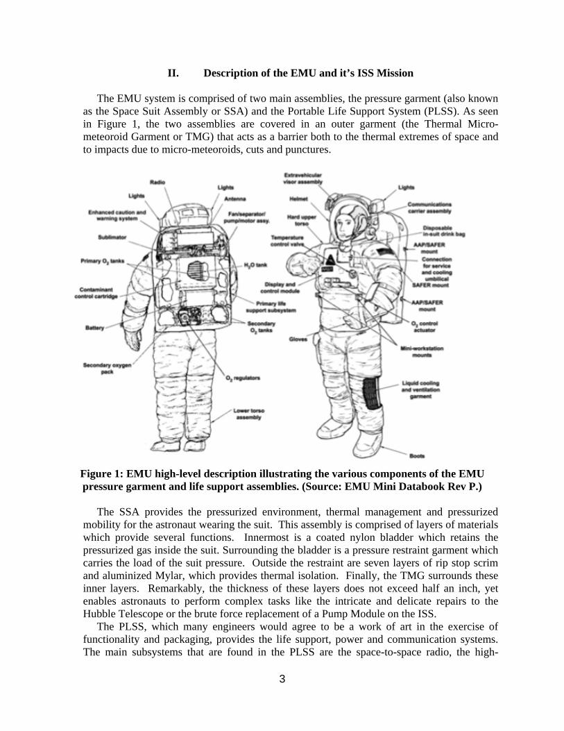
The EMU system is comprised of two main assemblies, the pressure garment (also known as the Space Suit Assembly or SSA) and the Portable Life Support System (PLSS). As seen in Figure 1, the two assemblies are covered in an outer garment (the Thermal Micro-meteoroid Garment or TMG) that acts as a barrier both to the thermal extremes of space and to impacts due to micro-meteoroids, cuts and punctures.
Figure 1: EMU high-level description illustrating the various components of the EMU pressure garment and life support assemblies. (Source: EMU Mini Databook Rev P.)
The SSA provides the pressurized environment, thermal management and pressurized mobility for the astronaut wearing the suit. This assembly is comprised of layers of materials which provide several functions. Innermost is a coated nylon bladder which retains the pressurized gas inside the suit. Surrounding the bladder is a pressure restraint garment which carries the load of the suit pressure. Outside the restraint are seven layers of rip stop scrim and aluminized Mylar, which provides thermal isolation. Finally, the TMG surrounds these inner layers. Remarkably, the thickness of these layers does not exceed half an inch, yet enables astronauts to perform complex tasks like the intricate and delicate repairs to the Hubble Telescope or the brute force replacement of a Pump Module on the ISS. The PLSS, which many engineers would agree to be a work of art in the exercise of functionality and packaging, provides the life support, power and communication systems. The main subsystems that are found in the PLSS are the space-to-space radio, the high-

4
pressure primary and secondary oxygen tanks, the primary and secondary water tanks for cooling, the fan/pump/separator, the METOX canister for CO2 removal, and the water Sublimator for cooling. These systems are monitored by the Enhanced Caution and Warning System (ECWS) and controlled by the spacewalker using the Display and Control Module (DCM). The PLSS is sized to support most astronauts for a seven hour EVA with and hour contingency; however, the actual maximum length of the EVA is determined the individual metabolic rate of the astronauts and the thermal environment of the EVA. The ISS EMU was originally developed for use on the U.S. Space Shuttle to mitigate failure scenarios where the Shuttle payload bay doors failed to close and lock properly prior to atmospheric re-entry. This initial risk mitigation required that the suit be able to pass through the Shuttle hatch openings to the crew cabin, which in turn sized the width and depth of the suit and PLSS assembly. The EMU has since evolved from a suit to help secure the Shuttle, to one capable of deploying, capturing and repairing satellites, and enabling astronauts to assemble and repair the ISS. As part of the evolutionary process to meet the expanding mission objectives of the EMU, the once single-mission operational certification (launch, EVA(s), land, refurbish) was incrementally extended to a mission life of multiple years on the ISS. The evolving mission of the suit has led to many changes to EMU components over the years. Those changes will not be addressed here; rather this paper will focus on impacts to the EMU water loops resulting from the life extension of the system, the on-orbit maintenance frequency and the development of on-orbit maintenance hardware (ALCLR hardware), required to keep the EMU system operational. The Joint Airlock in the U.S. segment of the ISS provides for EVA operations, and the continuous flight of the ISS requires spacesuits to be left on-board for longer periods of time than the suit’s original Shuttle certification allowed. The operations concept for the EMU evolved to launch EMUs on a Shuttle, leave a compliment of suits on ISS when the Shuttle un-docked, then on a subsequent Shuttle mission, replace and return those ISS suits to the ground for maintenance and refurbishment. To support continuous operation of the ISS, in 2000 the period of EMU maintenance cycles was extended from the 1-3 EVAs of a Shuttle mission to one year and 25 EVAs. Then in 2002 the maintenance interval was extended again to 2 years. In 2007 the certification was further extended to 3 years based upon significant engineering and maintenance data that suggested that this was possible. NASA’s decision to retire the Shuttle fleet required another evolution of the EMU operations concept. The complement of EMUs on ISS was increased from three to four, and an effort to integrate and certify the EMU for launch on the Japanese HTV was started. Until return capability for the EMU on an international or commercial vehicle becomes operational, the EMUs will be discarded when their life expires. In order to support the ISS to 2020 with the current inventory of EMUs, a new round of life extension took place in 2008 to extend the operational certification out to 6 years. In order to qualify the EMU hardware to meet the longer 6-year maintenance interval on-orbit in the ISS, the hardware is required to go through additional ground processing. This processing includes cleaning or replacing water filters along with the stripping and recoating areas of known susceptibility to corrosion (the water tank walls, aluminum horn, and Sublimator flange). These steps restore this hardware to the best possible condition right before a launch (Shuttle or alternate vehicle).1
5
III. Description of the EMU Water Loops
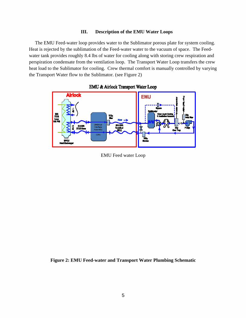
The EMU Feed-water loop provides water to the Sublimator porous plate for system cooling. Heat is rejected by the sublimation of the Feed-water water to the vacuum of space. The Feed-water tank provides roughly 8.4 lbs of water for cooling along with storing crew respiration and perspiration condensate from the ventilation loop. The Transport Water Loop transfers the crew heat load to the Sublimator for cooling. Crew thermal comfort is manually controlled by varying the Transport Water flow to the Sublimator. (see Figure 2)
EMU Feed water Loop
Figure 2: EMU Feed-water and Transport Water Plumbing Schematic
6
Maintaining both EMU water loops for long-term (6 year) operation presents the EMU team with significant challenges. The known risks to the loops, risks inherent in the current ISS mission, can be identified by past failures and by examining the interfaces between the EMU and ISS systems. The EMU Sublimator has failed in the past due to leachate from the EMU water bladders and from similar organic contaminants present in ISS-supplied water. The Fan/Pump/Separator and key transport loop filters have failed due to contaminants and corrosion products that are produced by EMU wetted components and by the ISS Airlock’s Low Temperature Loop Heat Exchanger, which provides cooling water for suited crewmembers prior to activating the EMU’s Sublimator. These failures are made more likely by extended stagnation time of the water in the EMU water loops. Besides these experienced failures, there is an additional source of risk to long-term operation of the EMU water loops. Once the current ISS cache of Shuttle-delivered water is expended, the water supply for the EMU hardware will, for the foreseeable life of the ISS, originate from the WPA. The water quality requirements of the WPA, the source for ISS-supplied water, do not align with the existing EMU water quality requirements. The WPA was designed primarily to produce potable water for astronaut consumption and hygiene. Only after the Shuttle program was cancelled did the need arise to use WPA water for EMUs. The WPA water quality requirements and monitoring are focused on contaminants that are a threat for human consumption, while threats to the EMU water loop components come from a different set of contaminants. Although current ground tests of WPA water show potential compatibility with the EMU Feed water Loop, a 2010 episode of increased TOC in the WPA product water illustrates the risk inherent for the EMU from regenerative water processing on ISS. The source of the high TOC, which was determined to be a compound called dimethylsilanediol, has not been conclusively determined. This episode points to the dynamic and unpredictable nature of regenerated resource streams on ISS and illustrates the risk of the “unknown unknowns’ while operating EMU water loops on the ISS. In the past there have been issues with water originating from ISS spanning from contamination from the airlock heat exchanger, to unexplained increases in TOC to unexpected leaching of acrylate-based leachate from WPA ion exchange resins. Each of these events was unexpected and required post-event remediation, new maintenance procedures, and hardware and (ground) testing to keep the EMU system viable. In 2003 EMU serial numbers 3005, 3011 & 3013 were left on-board the ISS after the Columbia accident and began to experience significant performance degradation and failure within approximately a year after being initially charged with water and launched to the ISS. The EMU hardware fan/pump/separators were not able to function. After extensive testing of the water in the system, and invasive forensic determination of the source of contaminates that had deposited on the fan blade, it was determined that the ISS Airlock heat exchanger was releasing nickel and silicon into the water and redepositing in the EMU fan/pump/separator along with biological material. After this event the development of the ALCLR hardware aided in removing the free ions in the water originating from the Airlock and provided a periodic disinfection capability. Through periodic testing via water samples and examination of EMUs returned from orbit, the ALCLR hardware is an effective mitigation to the EMU Feed-water contamination.2, 3, 4, 5 Starting in June of 2010, the ISS WPA effluent TOC levels began to rise unexpectedly until late October of that year. During testing with a mini-Sublimator (representative of the
7
full-sized unit, but requires less testing time to determine susceptibility to contamination) of water samples returned from the ISS to determine the affects of the rising TOC, the mini-Sublimator failed to meet required number of EVA hours. During subsequent investigation it was determined that an acrylate -based contaminant had formed a sublimation impeding film on the mini-Sublimator porous plate. Later it was determined the likely source of the acrylate-based contaminant was from one of the ion exchange resins in the ISS WPA MF filter beds. It was determined that the levels of acrylate-based contaminant decrease to a tolerable level after approximately 6,000 lbs of water have flown through the beds.
IV. Risk Reduction for Transport Water Loop
A. ALCLR Development and Implementation The ALCLR water processing kit was developed as a corrective action to EMU coolant loop flow disruptions experienced on the ISS in May of 2004 and thereafter. The components in the kit are designed to remove the contaminants that caused prior flow disruptions. ALCLR water processing kits have been utilized since 2004 as standard operating procedure. Periodic analysis of EMU coolant loop water and hardware examinations as a means to determine adequate functionality, optimized processing cycles, and ALCLR component shelf-life.2
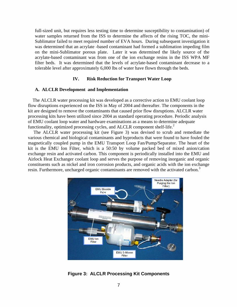
The ALCLR water processing kit (see Figure 3) was devised to scrub and remediate the various chemical and biological contaminants and byproducts that were found to have fouled the magnetically coupled pump in the EMU Transport Loop Fan/Pump/Separator. The heart of the kit is the EMU Ion Filter, which is a 50:50 by volume packed bed of mixed anion/cation exchange resin and activated carbon. This component is periodically installed into the EMU and Airlock Heat Exchanger coolant loop and serves the purpose of removing inorganic and organic constituents such as nickel and iron corrosion products, and organic acids with the ion exchange resin. Furthermore, uncharged organic contaminants are removed with the activated carbon.3
Figure 3: ALCLR Processing Kit Components
8
In service, a 3-micron filter is placed downstream of the EMU Ion Filter to captured fines from the packed bed prior to return of the polished water to the EMU Transport Loop. After scrubbing with the EMU Ion Filter, the EMU Biocide Filter is installed to add residual iodine biocide for microbial control. The EMU Biocide Filter is a packed bed of ion exchange resin impregnated with iodine.
B. ALCLR Cycle Enhancement The ALCLR storage cycle (storage period between EVA or ALCLR scrub activities) of 90-days or less was initially implemented when the ALCLR was first brought on-line post 2004 and the success of that cycle was validated with wetted hardware examinations and Transport Loop water analyses. An attempt to length the ALCLR storage cycle to up to 180-days was attempted in the 2007 time-frame, but wetted hardware examination and water analysis data suggested that this lengthened storage cycle was inadequate to manage the I-123 water pump fouling risk.4
From 2008 - 2010, wetted hardware examinations and EMU Transport Loop water analyses continued, to ensure adequate risk management. An additional request was made to continue to look at opportunities to extend the 90-day ALCLR storage cycle based on the data acquired from hardware that underwent ALCLR cycles between 90 - 180 days. That data was collected, but had not yielded dramatic, stand-alone findings that would justify an extension of the ALCLR storage cycle to beyond 90-days.5 An effort to data-mine and/or generate data to potentially justify an extension of the 90-day or less ALCLR storage cycle for the EMU hardware on the ISS was undertaken. That effort encompassed a more detailed review of existing data to identify data trends, specific gaps in the knowledge base, and a targeted acquisition of the gap data if that was indicated. The result of that effort was a detailed acquisition and review of all data pertinent to every EMU and ALCLR bed that was on the ISS for greater than three months since the 2004 implementation of the ALCLR. That data was organized into a spread sheet for ease of review, calculations, graphics and search capability.6 The data for each evaluated EMU and each ALCLR bed utilized, included launch and return dates, flight identification, number of uses and when, storage intervals, EVA profiles, ALCLR cycle profiles and ALCLR bed profiles. Furthermore, EMU Transport Loop chemical and microbial analysis results, sample grab dates and contaminant links to potential primary sources were included. Finally, the results of the examination of all pertinent hardware that is sensitive to trace contaminants (Item-123 Fan/Pump/Separator, Item-141Gas Trap and Item-127 Pump Inlet Filter) associated with each of the EMUs of interest, along with examination dates was included. All water analysis results and examination findings were condensed into a Transport Loop Health Index which underwent a Linear Correlation Coefficient Analysis against 15 factors that could potentially have an impact on the EMU Transport Loop health (see Figure 4) The preliminary conclusions drawn from the Linear Correlation Coefficient Analysis were as follows:
1) There was a high correlation between the health of an EMU Transport Loop and the number of post-ALCLR EVAs conducted (no ALCLR after last EVA episode(s)). That finding indicated that the poor water chemistry and state of the hardware after the 2007 attempt to extend the ALCLR storage cycle was more likely linked to 3-EVAs that were

9
conducted on the subject EMU just prior to ground return with no ALCLR thereafter, and not an increase in storage time from 90-days to 180-days as was previously thought.
2) There was a moderate correlation between the health of an EMU Transport Loop and the
total number of EVAs. The Transport Loop health appeared to be significantly better as fewer and fewer EVAs were conducted. That finding suggested that the potential future 1-year lag between ground EMU Transport Loop water charge at USA Houston, and launch from Japan would not require a pre-launch ALCLR cycle since no EVAs would have been conducted with the hardware.
3) Though weak, the next higher correlation was between the health of an EMU Transport
Loop and the time span from the initial ISS Air-Lock Heat Exchanger interface and the final sample grab. Again, that finding suggested that the potential 1-year lag between ground Transport Loop water charge at USA Houston, and launch from Japan would not require a pre-launch ALCLR cycle.
4) There appeared to be a weak to absent correlation between all six variants of storage time between ALCLR cycles that were examined and the health of the SEMU Transport Loop. The data suggests that there may be an argument to allow an extension of the time period in storage prior to ALCLR (< 90-days to TBD). The 2nd part of the ALCLR cycle study, which was underway at the time or this writing, will further explore that option.
When the previously described strong to moderate correlation between SEMU Transport Loop health and number of EVAs was considered in concert with the weak to absent correlation to storage time, there was a suggestion of a potential two-tier ALCLR cycle linked to the number of EVAs on an EMU that may take the following form:
< TBD EVAs = TBD increased allowable storage period > TBD EVAs = return to a < 90-day allowable storage period.
A cost/benefit analysis for any such a relief approach associated with the ALCLR cycle is also part of the ongoing 2nd phase of this study. Finally, SEMU 3009 was returned to ground on STS-135 after two years on ISS and 8-EVAs. That unit is undergoing an extended storage time after it underwent an ALCLR scrub shortly after ground return. The results of the Transport Loop water chemical/microbial analyses as well as disassembly and examination of all pertinent hardware (Item-123 Fan/Pump/Separator, Item-141Gas Trap and Item-127 Inlet Filter) will figure into the final decision on the potential for ALCLR cycle storage time relief

10
Figure 4: Correlation Coefficients vs. Performance Factors
C. ALCLR Fixed Bed Study
The intent of the ALCLR fixed bed study which is currently underway is to evaluate a means to minimize the amount of time the crew spent on performing EMU Transport Water Loop maintenance, to minimize the up/down mass of components used in the process, and to minimize the run-time on EMU components such as the I-123 Fan/Pump/Separator. This is in line with ISS efforts to reduce crew time used for the maintenance of ISS systems.7 This effort began with a detailed review of the equipment and methodology associated with the ALCLR process. Present ALCLR operational and functional requirements were reviewed to evaluate alternative approaches and to establish a baseline. It was determined that up to 55 hours per year of crew touch time is associated with pre and post EVA scrubbing and disinfection of the EMU Transport Loop water. The ALCLR process is conducted before and after each EVA, and is also conducted within 90-days of storage when the EMU hardware is not being utilized. Furthermore, ALCLR processing occurs on the Air Lock Heat Exchanger, the EMU Umbilical and LCVGs after they have been used at least once.

11
Three primary location categories were identified and include integration of the ALCLR hardware into the LSS itself, integration into the ISS Airlock coolant loop, and a stand-alone ALCLR scrubbing unit. Each either has, or will go through a detailed feasibility evaluation and a cost/benefit analysis with the current process used as the baseline. The first option that was considered was a fixed integration of the ALCLR hardware into the EMU LSS. There were only two locations with enough real estate to reasonably accommodate ALCLR-type hardware, which would have to be reconfigured to fit. The first location was near the EMU Water Pump Outlet Tube and the second was adjacent to the Reserve Water Tank near the ORU Harness. The location by the Water Pump Outlet Tube had the greater available real estate, but that location was deemed unacceptable since the reconfigured ALCLR hardware would only be able to support a single EVA, would drive additional crew maintenance, and the resultant pressure drop would be unacceptable to the system. Integration of the ALCLR hardware into the LSS was therefore deemed not feasible. The second option that was considered was integration into ISS Airlock coolant loop. Three feasible locations were identified and include near the UIA Panel above the UIA, at the IEU interface, and in the equipment locker near the vehicle heat exchanger. Of the three Airlock locations, the location in the equipment locker near the vehicle heat exchanger looks to be the most promising. Furthermore, that area may accommodate a resizing/reconfiguration of the ALCLR hardware, and a revisit to implementation of the cycle to minimize crew touch-time and component up/down mass. At the time of this writing, that location was still under evaluation. The third option, a stand-alone ALCLR unit, appears to be a very attractive option at the time of this writing. This approach could accommodate the greatest degree of resizing/reconfiguration of the ALCLR hardware, could accommodate a dedicated pump, and could conceivable be semi-automated to allow a significant reduction in crew touch-time. At the time of this writing, that approach is under evaluation. It should be noted that an independent assessment by NASA EC-5 has lead to consideration of a similar approach, and collaboration between Hamilton Sundstrand and NASA EC-5 on any follow-on to this effort is being explored.
V. Risk Reduction for the Feed-Water Loop
A. Testing to Validate WPA Source Water Testing was initiated in 2008 to evaluate the performance of a simulated EMU Sublimator with ground-generated ISS WPA effluent water at the NASA/MSFC facility. Water utilized for that first phase of testing was acquired from the flight WPA operated on the ground with an influent feed of DI water, essentially a functionality test. That water represented the water extractable material from wetted WPA materials of construction, and not the full range of potential contaminants to be processed by the operating WPA on ISS. 8
Performance test results from that first phase of testing were generated from testing with a small-scale test set-up referred to as the mini-Sublimator (see Figure 5) at Hamilton Sundstrand Windsor Locks. That first data set (see Figure 4) indicated that low-level extractable material from WPA wetted materials of construction could adversely impact the performance of an EMU Sublimator and would not allow for a50-EVA duration (25-EVA requirement x 2 safety factor – the post-Shuttle EMU requirement) before a need for porous plate change-out. The equivalent of 16-EVA duration was obtained before complete failure. Chemical analysis results suggested that

12
a source of the extractable material was an acrylic-based ion exchange resin utilized in the WPA MF bed.8
The water utilized for the second phase of testing was acquired from the flight WPA operated on the ISS with humidity condensate and urine distillate as the feed. It was returned on two separate Space Shuttle flights (~2.75 liters returned on STS-127, and ~0.75 liters returned on STS-128). It represented the water extractable material from wetted WPA materials of construction as well as the full range of contaminants processed when the WPA was operational on ISS. That water performed nominally with the mini-Sublimator, allowing a 50-EVA Sublimator test sequence to be completed (see Figure 6).
A third phase of activity entailed the testing of water acquired from the flight WPA soon after an MF bed change-out, to ensure that the acrylic-based ion exchange resin extract was not at a concentration that would be detrimental to EMU Sublimator performance soon after an MF bed change-out. Water was drawn from the ISS WPA on 08/01/10, shortly after an MF bed change out. At the time that the sample was drawn, ~ 460-lbs of water through put had been accumulated on the MF bed. That water was returned on STS-133 on 03/09/11 and tested on the mini- Sublimator thereafter. Testing showed that the flight-generated WPA water effluent failed the 50-EVA challenge test with the mini-Sublimator at a 37-EVA equivalence point (see Figure 6). Chemical analysis of the residue on the effluent side of the mini-porous plate indicated the presence of an acrylic-type compound, consistent with the extract from the MF bed acrylic-based ion exchange resin.9
Figure 5: Small Scale Sublimator Test Apparatus

13
A fourth phase of that study entailed the return of WPA water from the ISS on STS-135 after 6,216 lbs. of WPA MF-bed throughput.. The intent of that testing was two-fold as follows:
1) Evaluate the repeatability of prior test findings 2) Determine if water being processed by the WPA at that time could be stored for future
EMU Feed-water use at minimal risk. That final set of testing showed that the flight-generated WPA water effluent passed the full 350-hour mini-Sublimator performance test which is the equivalent of 50-EVAs (see Figure 6). That finding was compatible with previous findings that indicated that the acrylic-based ion exchange resin aqueous extract from the WMA MF beds is eventually reduced to the point where it is not detrimental to Sublimator performance. Based on those test results, it was recommended to collect and store WPA water for EMU-Feed-water use as long as the same MF beds were in place, the WPA effluent remained at < 0.5 ppm TOC, and the post-MF bed and post-VRA conductivity sensor performance remained nominal.10
Figure 6: Results of Sublimator Testing of All WPA Effluent Water
14
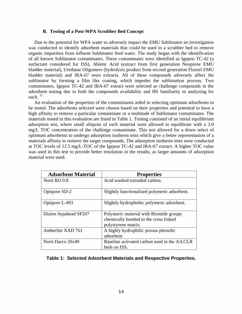
B. Testing of a Post-WPA Scrubber Bed Concept Due to the potential for WPA water to adversely impact the EMU Sublimator an investigation was conducted to identify adsorbent materials that could be used in a scrubber bed to remove organic impurities from influent Sublimator feed water. The study began with the identification of all known Sublimator contaminates. These contaminates were identified as Igepon TC-42 (a surfactant considered for ISS), Abietic Acid (extract from first generation Neoprene EMU bladder material), Urethane Oligomers (hydrolysis product from second generation Fluorel EMU bladder material) and IRA-67 resin extracts. All of these compounds adversely affect the sublimator by forming a film like coating, which impedes the sublimation process. Two contaminates, Igepon TC-42 and IRA-67 extract were selected as challenge compounds in the adsorbent testing due to both the compounds availability and HS familiarity in analyzing for each. 11
An evaluation of the properties of the contaminants aided in selecting optimum adsorbents to be tested. The adsorbents selected were chosen based on their properties and potential to have a high affinity to remove a particular contaminate or a multitude of Sublimator contaminates. The materials tested in this evaluation are listed in Table 1. Testing consisted of an initial equilibrium adsorption test, where small aliquots of each material were allowed to equilibrate with a 3.0 mg/L TOC concentration of the challenge contaminate. This test allowed for a down select of optimum adsorbents to undergo adsorption isotherm tests which give a better representation of a materials affinity to remove the target compounds. The adsorption isotherm tests were conducted at TOC levels of 12.5 mg/L-TOC of the Igepon TC-42 and IRA-67 extract. A higher TOC value was used in this test to provide better resolution in the results, as larger amounts of adsorption material were used.
Adsorbent Material Properties
Norit RO 0.8
Acid washed extruded carbon.
Optipore SD-2
Slightly functionalized polymeric adsorbent.
Optipore L-493
Slightly hydrophobic polymeric adsorbent.
Diaion Sepabead SP207
Polymeric material with Bromide groups chemically bonded to the cross linked polystyrene matrix.
Amberlite XAD 761
A highly hydrophilic porous phenolic adsorbent
Norit Darco 20x40
Baseline activated carbon used in the A/LCLR beds on ISS.
Table 1: Selected Adsorbent Materials and Respective Properties.

15
Prior to testing, each of the selected adsorbents underwent a washing step to remove any background leachates that could skew the results of the adsorption evaluation. The simplest way to monitor the adsorption potential of a material is to observe the TOC reduction during the test. If a material has high TOC due to organic leachates, it would be difficult to accurately determine if the contaminate challenge TOC is removed or if the TOC was a result of the adsorbent material itself. Washing of each material successfully decreased the background TOC levels prior to testing. However, to ensure these levels remained low, each adsorbent material underwent a leachate test in parallel with the equilibrium and isotherm adsorption evaluations. These leachate tests confirmed that a TOC increase was not observed with any of the selected adsorbent materials. Initial Equilibrium Testing The initial testing of the adsorption materials encompassed an equilibrium adsorption test, where the candidate materials were allowed to equilibrate with the challenge solutions of Igepon TC-42® and IRA-67® extract. For those tests, solutions of both Igepon TC-42® and IRA-67® extract were made to a 3.0 mg/L TOC level. The next step was to add 100 mL of each solution to flasks containing 0.25 and 0.50 grams of each adsorption material. Each flask was then placed on a stir place and mixed for a 24 hour period to come to equilibrium. Once completed, a sample was obtained from each flask and analyzed for TOC. The results allowed for the reduction of TOC to be determined for each sample and gave an indication which materials had an adsorption affinity for the selected contaminates. Results from the Igepon TC-42® equilibrium test are shown in Figure 7.
Figure 7: Equilibrium Adsorption Tests using Igepon
TC-42 and IRA-67 Extract as Challenge Solutions.
Results indicated that a majority of the materials tested had a high adsorption affinity for the Igepon TC-42®. One material which had limited capacity for the surfactant and IRA-67® extract was SD-2, and therefore was excluded from the results above. The adsorbent had the smallest pore diameter, which may have contributed to its poor performance. The Darco 20x40, RO 0.8, SP-207 and L-493 all had similar affinities for Igepon TC-42®, with TOC removal averaging
0
10
20
30
40
50
60
70
80
90
100
SP‐207 L‐493 XAD 761 Darco 20x40 RO 0.8
TOC % Removal
Igepon TC‐42 0.25 grams
0.5 grams
0
10
20
30
40
50
60
70
80
90
100
SP‐207 L‐493 XAD 761 Darco 20x40 RO 0.8
TOC % Removal
IRA‐67 Extract
0.5 grams
0.25 grams

16
95%. The materials down selected to undergo adsorption isotherm testing included RO 0.8, SP-207 and L-493. Results for the equilibrium test using IRA-67® extract as a challenge compound are also displayed in Figure 8. This compound proved to be more difficult to remove, as only one material sufficiently reduced TOC more than 90%. The data also suggests that a carbon material is indeed insufficient to remove the acrylic extract. This can be seen in the results for the Darco 20x40 and RO 0.8, both which are carbon based materials. XAD 761 and L-493 polymeric adsorbents showed the highest affinity to remove the IRA-67® extract and therefore were down selected to undergo additional adsorption isotherm testing.
Adsorption Isotherm Testing Additional testing was performed on adsorbent material that showed favorable results in the equilibrium testing for the IRA-67® extract. This testing involved a series of adsorption isotherms to determine the effects of varying adsorption material mass under a constant TOC concentration. Each isotherm consisted of the following samples 0.0, 0.1, 0.25, 0.50 and1.0 grams of adsorption material. The material was placed in 40 mL vials and filled with a 12.5 mg/L TOC solution of IRA-67® extract. The samples were then mixed for 12 hours and then filtered and analyzed for TOC concentration. The selected adsorbents from the IRA-67® extract testing were L-493 and XAD 761. The results for these tests are displayed in Figure 8.
Figure 8: Adsorption Isotherm Results for IRA-67® Extract (A) Polymeric Adsorbent L-493 (B) Polymeric Adsorbent XAD 761
(A) (B)
17
The results from this evaluation illustrate that a multitude of adsorbents exist that have a greater affinity for contaminate removal than the baseline Darco 20x40. If a scrubber bed were to be implemented on ISS, it could conceivably contain a mixture of adsorbents to target specific contaminates in the feed water. This study should be considered a first step in the process of developing a scrubber bed.
C. Porous Plate ORU
The heat rejection mechanism for the EMU is a porous plate Sublimator. The availability of space vacuum allows for water to go from the solid to vapor state on the surface of the porous plate. The Sublimator rejects heat from the crewmember metabolic load of up to 2000 Btu/Hr in addition to the heat produced by the life support system and heat absorbed by the EMU from the environment. As previously discussed, the porous plate is sensitive to trace contaminants that can impede the sublimation process. If a plate is adversely impacted by trace contaminants, it cannot maintain the required heat rejection properties. During the Shuttle program the EMU supply water was generated either from the Shuttle fuel cells or on the ground. With Shuttle retirement, alternate sources of water such as the ISS WPA have been considered. If a Sublimator were to be adversely contaminated, that would jeopardize the on-orbit mission life of 25-EVAs. The present EMU Sublimator has two porous plates, a Large Primary Plate and a Supplemental Plate. The Large Primary Plate is sandwiched between a stainless steel grid and an aluminum core. The edge is sealed with a thin Kapton® film. Current porous plate change out on the ground requires a careful process to preclude edge leakage. On orbit replacement of the present main Porous Plate would require handling of the thin film seal, numerous loose fasteners, the Porous Plate itself, and the support grid. Besides being unwieldy, obtaining acceptable leakage performance would be a challenge. Several options have been considered to facilitate on-orbit change out of a porous plate. These include bonding the seal to the plate to prevent handling of the thin film in zero gravity and the development of an integrated seal and plate. All designs would require careful evaluation because a change in dimensions could impact the flow distribution to the plate or the overall heat transfer effectiveness. Another option under consideration is to mature the concept of an intermediate plate between the porous plate and Sublimator core with the use of standard silicone seals. An aluminum plate could be placed in the larger water gap to lessen the heat transfer reduction that would be expected. The addition of intermediate plate components would increase the thickness of the Sublimator, moving the assembly closer to the Caution Warning System Assembly, thus closing up the gap for water vapor flow from the Porous Plate. The intermediate Porous Plate approach has a good chance of resulting in a sealed porous plate, but the risk is a reduction in cooling capacity. At the time of this writing, no formal efforts to redesign the Sublimator have been undertaken beyond the basic concept stage briefly described in this paper.
18
D. Fluorel Bladder Reformulation
The EMU has three polymeric bladders (one large and two small) that store the approximately 8.5 lbs. of water charged for each EVA. At the start of the Program (1981), those bladders were made of Neoprene Latex. An early version of the Neoprene Latex Bladder leached relatively high chloride levels which lead to aluminum corrosion challenges for the EMU. The later version of the Neoprene Latex Bladder leached an organic acid that formed a film on the effluent side of the Sublimator Porous Plate, significantly impacting Sublimator performance. The Neoprene Latex Bladder material was replaced with a fluorocarbon-based polymer called Fluorel in the mid-1980s, and the balance of the EMU fleet has been outfitted with Fluorel Bladders since. The Fluorel Bladder formulation that was used provided the physical properties necessary for the application, and did not leach film-forming contaminants that impacted Sublimator performance. Fluorel Bladders were certified for 25-EVAs thereafter to support the ISS assembly and post-Shuttle long-term EMU needs for ISS . Due to attrition, the EMU Program requested additional Fluorel Bladders to be made in 2010. During the manufacture of those bladders, it was determined that one of the formulation constituents had changed such that there was a significant shift in the physical properties of compression set and elongation, and an increase in contaminants that impacted Sublimator performance. Minor adjustments to the formulation, and a source change for the changed formulation constituent had resulted in a challenge to acquire both the desirable material physical properties and the low leach profile of the original Fluorel Bladder formulation. Efforts are now underway to resolve the above-mentioned challenge with a four-option study as follows:
Option 1 - Investigate new materials
Option 2 - Continue with variations of the original formulation and variations to the replacement constituent that had changed Option 3 – Development of a solvent leach cycle to remove Sublimator-degrading constituents after a bladder had been manufactured Option 4 – Determine if the reduced physical properties of compression set and elongation would be acceptable to the application at hand.
At the time of this writing Option 2 had shown great promise with enhanced physical properties comparable to those achieved with the original Fluorel Bladders, significantly reduced extractable material, and nominal Sublimator performance test results. Options 1 & 3 are progressing, and Option 4 is on-hold due to the promising results achieved with Option 2.
VI. Conclusions
The mission of the EMU has evolved over the years, from an up/down 7-10 day Shuttle contingency system with the luxury of a revamp once on the ground, to a 25-EVA/6-year mission on the ISS with minimal servicing. This mission expansion has resulted in significant
19
challenges to the maintenance of the water quality in the two EMU water loops. A number of efforts have been undertaken to minimize EMU performance risk related to water quality degradation. Those efforts include the development and implementation of hardware to scrub and disinfect water in the EMU Transport Loop, a streamlining of the scrub/disinfect process, and the investigation of approaches to reduce crew touch time and minimize required up-mass for the scrub/disinfection process. Efforts are also underway to minimize the risk of using the ISS WPA effluent water for the EMU Feed-water including the characterization of trace Sublimator contaminants originating from the WPA, performance testing associated with nuances of the WPA duty cycle such as water throughput as a function of Sublimator risk, and concepts for further scrubbing of WPA effluent for the EMU if required. Finally, material obsolescence as exemplified by a need to reformulate the EMU Fluorel bladder presents risk to EMU water quality which is being addressed.
VII. References 1 West, William, Witt, Vincent, Chullen, Cinda, AIAA-2010-6130-610, EVA 2010: Preparing for International Space Station EVA Operations Post-Space Shuttle Retirement. 2 Lewis, J. F., Cole, H., Cronin, G., Gazda, D. B., Steele, J. W., “Extravehicular Mobility Unit (EMU)/ International Space Station (ISS) Coolant Loop Failure and Recovery”, ICES Paper, 2006-01-2040.
3 Steele, J.W., Rector, T., “Airlock Cooling Loop Recovery (A/L CLR) Sampling and Analysis Results – Phase II”, Hamilton Sundstrand Internal Document SVME: 6057H.
4 Steele, J. W., Gazda, D. B., Lewis, J. F., Rector, T., “Performance of the Extravehicular Mobility Unit (EMU) Airlock Coolant Loop Recovery (ALCLR) Hardware, ICES Paper, 08ICES-0023. 5 Steele, J. W., Gazda, D. B., Lewis, J. F., Rector, T., “Performance of the Extravehicular Mobility Unit (EMU) Airlock Coolant Loop Recovery (ALCLR) Hardware - Final, AIAA 2011-5259. 6 Steele, J. W., “DO-22 - “EMU ALCLR Scrub Interval Study – Interim Report”, 12/2011, Hamilton Sundstrand Internal Document SVME: 6625E. 7 Kalnenieks, P. T., DO -24 “Special Study for Incorporation of a Permanent ALCLR Scrubber Bed” - Interim Report, 01/2012, Hamilton Sundstrand Internal Document. 8 Morenz, J., Steele, J. W., “EMU Sublimator Performance Using WPA Water”, 09/2009, Hamilton Sundstrand Internal Document SVME: 6083A. 9 Steele, J. W., “EMU Sublimator Performance with Flight Generated WPA Water Soon After an MF Bed Change- Out”, 07/2011, Hamilton Sundstrand Internal Document SVME: 6502C. 10 Steele, J. W., “EMU Sublimator Performance Using Flight Generated WPA Water Returned on STS-135”, 01/2012, Hamilton Sundstrand Internal Document SVME: 6615A. 11 Rector, T., “WPA Water Feasibility Scrubber Bed Study”, 06/2011, Hamilton Sundstrand Internal Document SVME: 6481.