EMS by Muneeb Yaqoob
27
Electrical Machines Chapter 1 CHAPTER 1 – Introduction to Machinery Principles Summary: 1. Basic concept of ele ctric al machin es fund ament als: o Rotational component measurements Angular Velocity, Acceleration or!ue, "or#, $o%er &e%ton's (a% of Rotation o Magnetic )ield study $roduction of a Magnetic )ield Magnetic Circuits *. Magne tic B eha+io ur of )erromagneti c Mat erials . -o% magnet ic fie ld ca n affe ct it s surro unding s: • )ar ada y's (a% /ndu ced Vol tage from a ime0Ch anging Mag net ic )ield. • $roduction of /nduced )orce on a "ire. • /nduced Voltage on a Conductor mo+ing in a Magnetic )ield . (i near 2C Ma chines 1
-
Upload
salman-tauqeer -
Category
Documents
-
view
238 -
download
0
Transcript of EMS by Muneeb Yaqoob

8/12/2019 EMS by Muneeb Yaqoob
http://slidepdf.com/reader/full/ems-by-muneeb-yaqoob 1/27
Electrical MachinesChapter 1
CHAPTER 1 – Introduction to Machinery Principles
Summary:
1. Basic concept of electrical machines fundamentals:o Rotational component measurements
Angular Velocity, Accelerationor!ue, "or#, $o%er
&e%ton's (a% of Rotationo Magnetic )ield study
$roduction of a Magnetic )ieldMagnetic Circuits
*. Magnetic Beha+iour of )erromagnetic Materials
. -o% magnetic field can affect its surroundings:• )araday's (a% /nduced Voltage from a ime0Changing Magnetic
)ield.• $roduction of /nduced )orce on a "ire.• /nduced Voltage on a Conductor mo+ing in a Magnetic )ield
. (inear 2C Machines
1
8/12/2019 EMS by Muneeb Yaqoob
http://slidepdf.com/reader/full/ems-by-muneeb-yaqoob 2/27

8/12/2019 EMS by Muneeb Yaqoob
http://slidepdf.com/reader/full/ems-by-muneeb-yaqoob 3/27
Electrical MachinesChapter 1
t time ta#en for the rotating 5ody to tra+erse the specified distance, ϑ.Angular acceleration! 0 is defined as the rate of change in angular +elocity %ith respect to time. /tsformulation is as sho%n:
d dt ω
α = rad=s*;
Tor)ue! τ
1. /n linear motion, a force applied to an o57ect causes its +elocity to change. /n the a5sence of anet force on the o57ect, its +elocity is constant. he greater the force applied to the o57ect, themore rapidly its +elocity changes.
*. Similarly in the concept of rotation, %hen an o57ect is rotating, its angular +elocity is constantunless a tor!ue is present on it. 3reater the tor!ue, more rapid the angular +elocity changes.
. or!ue is #no%n as a rotational force applied to a rotating 5ody gi+ing angular acceleration,a.#.a. >t%isting force'.
. 2efinition of or!ue: &m;
‘Product of force applied to the object and the smallest distance between the line of action of the force and the object’s axis of rotation’
)orce perpendicular distance
sin F r
τ θ
∴ = ×= ×
θ
Directionof rotation
rsin (180 − θ) = rsin θ
F
*or+! * is defined as the application of )orce through a distance. herefore, %or# may 5e defined as:
W Fdr =∫ Assuming that the direction of ) is collinear in the same direction; %ith the direction of motion andconstant in magnitude, hence,
W Fr =Applying the same concept for rotating 5odies,
W d τ θ =∫ Assuming that τ is constant,
W τθ = ?oules;

8/12/2019 EMS by Muneeb Yaqoob
http://slidepdf.com/reader/full/ems-by-muneeb-yaqoob 4/27
net I dl H =∫
Electrical MachinesChapter 1
Po#er! P is defined as rate of doing %or#. -ence,
dW P
dt = %atts;
Applying this for rotating 5odies,
( )d
P dt
d
dt
τθ
θ τ
τω
=
=
=his e!uation can descri5e the mechanical po%er on the shaft of a motor or generator.
"e#ton$s %a# of Rotation
&e%ton's la% for o57ects mo+ing in a straight line gi+es a relationship 5et%een the force applied to theo57ect and the acceleration e@perience 5y the o57ect as the result of force applied to it. /n general,
F ma=%here:
) )orce appliedm mass of o57ecta resultant acceleration of o57ect
Applying these concept for rotating 5odies, J
τ α = &m;%here:
τ 0 or!ue? moment of inertiaα 0 angular acceleration
1., The Magnetic -ield
Magnetic fields are the fundamental mechanism &y #hich energy is con erted from one form toanother in motors, generators and transformers.
)irst, %e are going to loo# at the 5asic principle A current/carrying #ire produces a magnetic fieldin the area around it.
Production of a Magnetic -ield
1. Ampere$s %a# – the 5asic la% go+erning the production of a magnetic field 5y a current:
%here H is the magnetic field intensity produced 5y the current / net and dl is a differential element oflength along the path of integration. - is measured in Ampere0turns per meter.

8/12/2019 EMS by Muneeb Yaqoob
http://slidepdf.com/reader/full/ems-by-muneeb-yaqoob 5/27
H B µ =
Electrical MachinesChapter 1
*. Consider a current currying conductor is %rapped around a ferromagnetic core
mean path length, l c
I
φ
N turns
CSA
. Applying Ampere's la%, the total amount of magnetic field induced %ill 5e proportional to theamount of current flo%ing through the conductor %ound %ith & turns around the ferromagneticmaterial as sho%n. Since the core is made of ferromagnetic material, it is assume that a ma7orityof the magnetic field %ill 5e confined to the core.
. he path of integration in Ampere's la% is the mean path length of the core, l c. he current passing %ithin the path of integration / net is then &i, since the coil of %ires cuts the path ofintegration & times %hile carrying the current i. -ence Ampere's (a% 5ecomes,
c
c
Hl i
i H
l
=
∴ =
6. /n this sense, - Ampere turns per metre; is #no%n as the effort re!uired to induce a magneticfield. he strength of the magnetic field flu@ produced in the core also depends on the material ofthe core. hus,
B magnetic flu@ density %e5ers per s!uare meter, esla ;; magnetic permea5ility of material -enrys per meter;
- magnetic field intensity ampere0turns per meter;
8. he constant µ may 5e further e@panded to include relative permeabilit! %hich can 5e defined as 5elo%:
r
o
µ µ µ
=
%here: µo permea5ility of free space a.#.a. air;
D. -ence the permea5ility +alue is a com5ination of the relati+e permea5ility and the permea5ility offree space. he +alue of relati+e permea5ility is dependent upon the type of material used. hehigher the amount permea5ility, the higher the amount of flu@ induced in the core. Relati+e
permea5ility is a con+enient %ay to compare the magneti a5ility of materials.
F. Also, 5ecause the permea5ility of iron is so much higher than that of air, the ma7ority of the flu@in an iron core remains inside the core instead of tra+elling through the surrounding air, %hich haslo%er permea5ility. he small lea#age flu@ that does lea+e the iron core is important indetermining the flu@ lin#ages 5et%een coils and the self0inductances of coils in transformers andmotors.
6

8/12/2019 EMS by Muneeb Yaqoob
http://slidepdf.com/reader/full/ems-by-muneeb-yaqoob 6/27
Electrical MachinesChapter 1
G. /n a core such as in the figure,
B µ- c
l
i µ
&o%, to measure the total flu@ flo%ing in the ferromagnetic core, consideration has to 5e made in
terms of its cross sectional area CSA;. herefore,
"
Bd"φ =∫ "here: A cross sectional area throughout the core
Assuming that the flu@ density in the ferromagnetic core is constant throughout hence constantA, the e!uation simplifies to 5e:
B"φ =
a#ing into account past deri+ation of B,
c
i"
l
µ φ =
,. Magnetics Circuits
he flo% of magnetic flu@ induced in the ferromagnetic core can 5e made analogous to an electricalcircuit hence the name magnetic circuit.
he analogy is as follo%s:
+
-
A
RV+
-
φ
Reluctance, RF=Ni(mmf)
#lectric $ircuit "nalo%! &a%netic $ircuit "nalo%!
1. Referring to the magnetic circuit analogy, ) is denoted as magnetomoti e force mmf; %hich issimilar to Electromoti+e force in an electrical circuit emf;. herefore, %e can safely say that ) isthe prime mo+er or force %hich pushes magnetic flu@ around a ferromagnetic core at a +alue of
&i refer to ampere's la%;. -ence ) is measured in ampere turns. -ence the magnetic circuite!ui+alent e!uation is as sho%n:
F 'φ = similar to V /R;
*. he polarity of the mmf %ill determine the direction of flu@. o easily determine the direction offlu@, the >right hand curl' rule is utilised:
a; he direction of the curled fingers determines the current flo%. 5; he resulting thum5 direction %ill sho% the magnetic flu@ flo%.
8

8/12/2019 EMS by Muneeb Yaqoob
http://slidepdf.com/reader/full/ems-by-muneeb-yaqoob 7/27
Electrical MachinesChapter 1
. he element of R in the magnetic circuit analogy is similar in concept to the electrical resistance./t is 5asically the measure of material resistance to the flo% of magnetic flu@. Reluctance in thisanalogy o5eys the rule of electrical resistance Series and $arallel Rules;. Reluctance is measuredin Ampere0turns per %e5er.
Series Reluctance,Re! R1 < R* < R < H.
$arallel Reluctance,
1 * ,
1 1 1 1...
e( ' ' ' '= + + +
. he in+erse of electrical resistance is conductance %hich is a measure of conducti+ity of amaterial. -ence the in+erse of reluctance is #no%n as permeance! P %here it represents thedegree at %hich the material permits the flo% of magnetic flu@.
1
since
P ' F ' FP
φ
φ
=
∴ =
∴ =Also,
,
c
c
c
c
c
i"
l
" i
l
" F
l
" l P '
l "
µ φ
µ
µ
µ µ
=
=
=
∴ = =
6. By using the magnetic circuit approach, it simplifies calculations related to the magnetic field in aferromagnetic material, ho%e+er, this approach has inaccuracy em5edded into it due toassumptions made in creating this approach %ithin 6I of the real ans%er;. $ossi5le reason ofinaccuracy is due to:
a; he magnetic circuit assumes that all flu@ are confined %ithin the core, 5ut in reality a smallfraction of the flu@ escapes from the core into the surrounding lo%0permea5ility air, and this flu@is called lea+age flu' .
5; he reluctance calculation assumes a certain mean path length and cross sectional area csa; ofthe core. his is alright if the core is 7ust one 5loc# of ferromagnetic material %ith no corners, for
practical ferromagnetic cores %hich ha+e corners due to its design, this assumption is notaccurate.
D

8/12/2019 EMS by Muneeb Yaqoob
http://slidepdf.com/reader/full/ems-by-muneeb-yaqoob 8/27
Electrical MachinesChapter 1
c; /n ferromagnetic materials, the permea5ility +aries %ith the amount of flu@ already in thematerial. he material permea5ility is not constant hence there is an e@istence of non/linearityof permea&ility.
d; )or ferromagnetic core %hich has air gaps, there are fringing effects that should 5e ta#en intoaccount as sho%n:
N
S
E'ample 1.1
A ferromagnetic core is sho%n. hree sides of this core are of uniform %idth, %hile the fourth side issome%hat thinner. he depth of the core into the page; is 1Jcm, and the other dimensions are sho%n inthe figure. here is a *JJ turn coil %rapped around the left side of the core. Assuming relati+e
permea5ility r of *6JJ, ho# much flu' #ill &e produced 5y a 1A input current9
)olution* sides of the core ha+e the same csa, %hile the th side has a different area. hus the core can 5e di+ided
into * regions:1; the single thinner side*; the other sides ta#en together
he magnetic circuit corresponding to this core:
F
8/12/2019 EMS by Muneeb Yaqoob
http://slidepdf.com/reader/full/ems-by-muneeb-yaqoob 9/27
Electrical MachinesChapter 1
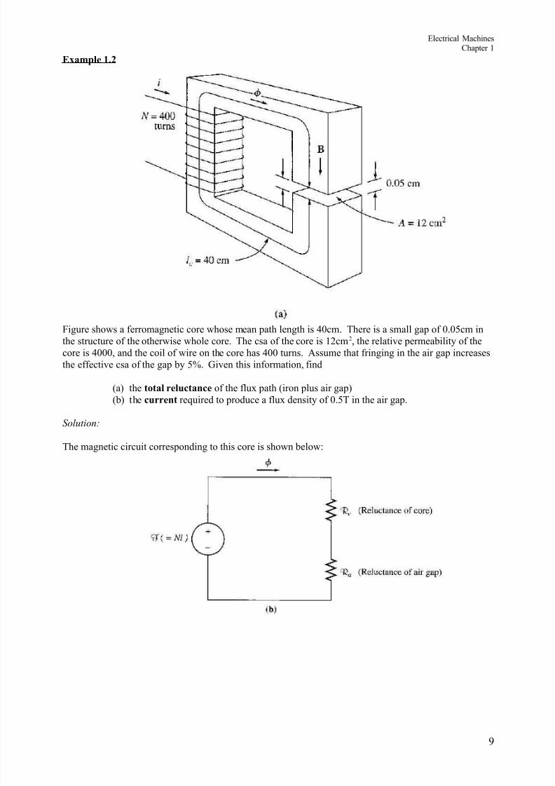
E'ample 1.,
)igure sho%s a ferromagnetic core %hose mean path length is Jcm. here is a small gap of J.J6cm inthe structure of the other%ise %hole core. he csa of the core is 1*cm *, the relati+e permea5ility of thecore is JJJ, and the coil of %ire on the core has JJ turns. Assume that fringing in the air gap increasesthe effecti+e csa of the gap 5y 6I. 3i+en this information, find
a; the total reluctance of the flu@ path iron plus air gap;5; the current re!uired to produce a flu@ density of J.6 in the air gap.
)olution*
he magnetic circuit corresponding to this core is sho%n 5elo%:
G

8/12/2019 EMS by Muneeb Yaqoob
http://slidepdf.com/reader/full/ems-by-muneeb-yaqoob 10/27
Electrical MachinesChapter 1
E'ample 1.0
)igure sho%s a simplified rotor and stator for a dc motor. he mean path length of the stator is 6Jcm,and its csa is 1*cm *. he mean path length of the rotor is 6 cm, and its csa also may 5e assumed to 5e1*cm *. Each air gap 5et%een the rotor and the stator is J.J6cm %ide, and the csa of each air gap
including fringing; is 1 cm *. he iron of the core has a relati+e permea5ility of *JJJ, and there are *JJturns of %ire on the core. /f the current in the %ire is ad7usted to 5e 1A, %hat %ill the resulting flu'density in the air gaps 5e9
)olution*
o determine the flu@ density in the air gap, it is necessary to first calculate the mmf applied to the coreand the total reluctance of the flu@ path. "ith this information, the total flu@ in the core can 5e found.)inally, #no%ing the csa of the air gaps ena5les the flu@ density to 5e calculated.
he magnetic cct corresponding to this machine is sho%n 5elo%.
1J

8/12/2019 EMS by Muneeb Yaqoob
http://slidepdf.com/reader/full/ems-by-muneeb-yaqoob 11/27
Electrical MachinesChapter 1
Magnetic eha iour of -erromagnetic Materials
1. Materials %hich are classified as non0magnetic all sho% a linear relationship 5et%een the flu@density B and coil current /. /n other %ords, they ha+e constant permea5ility. hus, for e@ample,in free space, the permea5ility is constant. But in iron and other ferromagnetic materials it is notconstant.
*. )or magnetic materials, a much larger +alue of B is produced in these materials than in free space.herefore, the permea5ility of magnetic materials is much higher than o. -o%e+er, the
permea5ility is not linear anymore 5ut does depend on the current o+er a %ide range.
. hus, the permea&ility is the property of a medium that determines its magneticcharacteristics . /n other %ords, the concept of magnetic permea5ility corresponds to the a5ility ofthe material to permit the flo% of magnetic flu@ through it.
. /n electrical machines and electromechanical de+ices a some%hat linear relationship 5et%een Band / is desired, %hich is normally approached 5y limiting the current.
6. (oo# at the magneti ation cur+e and B0- cur+e. &ote: he cur+e corresponds to an increase of 2Ccurrent flo% through a coil %rapped around the ferromagnetic core ref: Electrical Machinery)undamentals th Ed. Stephen ? Chapman;.
8. "hen the flu@ produced in the core is plotted +ersus the mmf producing it, the resulting plot loo#sli#e this a;. his plot is called a saturation cur e or a magneti ation cur e. A small increase inthe mmf produces a huge increase in the resulting flu@. After a certain point, further increases inthe mmf produce relati+ely smaller increases in the flu@. )inally, there %ill 5e no change at all asyou increase mmf further. he region in %hich the cur+e flattens out is called saturation region,and the core is said to 5e saturated. he region %here the flu@ changes rapidly is called theunsaturated region . he transition region is called the >#nee' of the cur+e.
D. )rom e!uation - &i=l c )=lc and BA, it can 5e seen that magneti ing intensity is directly proportional to mmf and magnetic flu@ density is directly proportional to flu@ for any gi+en core.B - slope of cur+e is the permea5ility of the core at that magneti ing intensity. he cur+e 5;sho%s that the permea5ility is large and relati+ely constant in the unsaturated region and thengradually drops to a lo% +alue as the core 5ecome hea+ily saturated.
F. Ad+antage of using a ferromagnetic material for cores in electric machines and transformers is thatone gets more flu@ for a gi+en mmf than %ith air free space;.
11

8/12/2019 EMS by Muneeb Yaqoob
http://slidepdf.com/reader/full/ems-by-muneeb-yaqoob 12/27
Electrical MachinesChapter 1
G. /f the resulting flu@ has to 5e proportional to the mmf, then the core must 5e operated in theunsaturated region.
1J. 3enerators and motors depend on magnetic flu@ to produce +oltage and tor!ue, so they need asmuch flu@ as possi5le. So, they operate near the #nee of the magneti ation cur+e flu@ not linearlyrelated to the mmf;. his non0linearity as a result gi+es peculiar 5eha+iours to machines.
11. As magneti ing intensity - increased, the relati+e permea5ility first increases and then starts todrop off.
E'ample 1.2
A s!uare magnetic core has a mean path length of 66cm and a csa of 16Jcm *. A *JJ turn coil of %ire is%rapped around one leg of the core. he core is made of a material ha+ing the magneti ation cur+esho%n 5elo%. )ind:
a; -o% much current is re!uired to produce J.J1* "5 of flu@ in the core9 5; "hat is the core's relati+e permea5ility at that current le+el9c; "hat is its reluctance9
1*

8/12/2019 EMS by Muneeb Yaqoob
http://slidepdf.com/reader/full/ems-by-muneeb-yaqoob 13/27
Electrical MachinesChapter 1
Energy %osses in a -erromagnetic Core
/. -ysteresis (oss
1. 2iscussions made 5efore concentrates on the application of a 2C current through the coil. &o%let's mo+e the discussion into the application of AC current source at the coil. Ksing ourunderstanding pre+iously, %e can predict that the cur+e %ould 5e as sho%n,
φ
F
1st Positi eC!cle
"n# Ne$ati eC!cle
+heoretical ac ma%netic behaviour for flux in a ferroma%netic core,
*. Knfortunately, the a5o+e assumption is only correct pro+ided that the core is >perfect' i.e. there areno residual flu@ present during the negati+e cycle of the ac current flo%. A typical flu@ 5eha+iour
or #no%n as hysteresis loop; in a ferromagnetic core is as sho%n in the ne@t page.
1
8/12/2019 EMS by Muneeb Yaqoob
http://slidepdf.com/reader/full/ems-by-muneeb-yaqoob 14/27
Electrical MachinesChapter 1
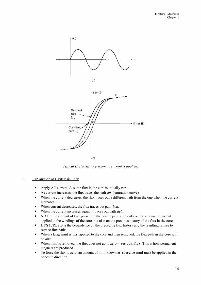
+!pical H!sterisis loop when ac current is applied,
. E@planation of -ysteresis (oop
• Apply AC current. Assume flu@ in the core is initially ero.• As current increases, the flu@ traces the path ab, saturation cur+e;• "hen the current decreases, the flu@ traces out a different path from the one %hen the current
increases.• "hen current decreases, the flu@ traces out path bcd .• "hen the current increases again, it traces out path deb .• &4 E: the amount of flu@ present in the core depends not only on the amount of current
applied to the %indings of the core, 5ut also on the pre+ious history of the flu@ in the core.• -LS ERES/S is the dependence on the preceding flu@ history and the resulting failure to
retrace flu@ paths.• "hen a large mmf is first applied to the core and then remo+ed, the flu@ path in the core %ill
5e abc .• "hen mmf is remo+ed, the flu@ does not go to ero residual flu' . his is ho% permanent
magnets are produced.• o force the flu@ to ero, an amount of mmf #no%n as coerci e mmf must 5e applied in theopposite direction.
1

8/12/2019 EMS by Muneeb Yaqoob
http://slidepdf.com/reader/full/ems-by-muneeb-yaqoob 15/27
Electrical MachinesChapter 1
. "hy does hysteresis occur9
o understand hysteresis in a ferromagnetic core, %e ha+e to loo# into the 5eha+iour of itsatomic structure 5efore, during and after the presence of a magnetic field.
he atoms of iron and similar metals co5alt, nic#el, and some of their alloys; tend to ha+etheir magnetic fields closely aligned %ith each other. "ithin the metal, there is an e@istenceof small regions #no%n as domains %here in each domain there is a presence of a smallmagnetic field %hich randomly aligned through the metal structure.
his as sho%n 5elo%:
"n example of a ma%netic domain orientation in a metal structure before the presence of a ma%netic field,
Magnetic field direction in each domain is random as such that the net magnetic field is ero.
"hen mmf is applied to the core, each magnetic field %ill align %ith respect to the direction ofthe magnetic field. hat e@plains the e@ponential increase of magnetic flu@ during the early stageof magnetisation. As more and more domain are aligned to the magnetic field, the total magneticflu@ %ill maintain at a constant le+el hence as sho%n in the magnetisation cur+e saturation;.
"hen mmf is remo+ed, the magnetic field in each domain #ill try to re+ert to its random state.
-o%e+er, not all magnetic field domain's %ould re+ert to its random state hence it remained inits pre+ious magnetic field position. his is due to the lac# of energy re!uired to distur5 themagnetic field alignment.
-ence the material %ill retain some of its magnetic properties permanent magnet; up until ane@ternal energy is applied to the material. E@amples of e@ternal energy may 5e in the form of
heat or large mechanical shoc#. hat is %hy a permanent magnet can lose its magnetism if it isdropped, hit %ith a hammer or heated.
herefore, in an ac current situation, to realign the magnetic field in each domain during theopposite cycle %ould re!uire e@tra mmf also #no%n as coerci+e mmf;.
his e@tra energy re!uirement is #no%n as hysteresis loss .
he larger the material, the more energy is re!uired hence the higher the hysteresis loss.
Area enclosed in the hysteresis loop formed 5y applying an ac current to the core is directly
proportional to the energy lost in a gi+en ac cycle.
16

8/12/2019 EMS by Muneeb Yaqoob
http://slidepdf.com/reader/full/ems-by-muneeb-yaqoob 16/27
dt
d eind
φ −=
dt
d e
ind
φ −=
Electrical MachinesChapter 1
//. Eddy Current (oss
1. A time0changing flu@ induces +oltage %ithin a ferromagnetic core.*. hese +oltages cause s%irls of current to flo% %ithin the core eddy currents.
. Energy is dissipated in the form of heat; 5ecause these eddy currents are flo%ing in a resisti+ematerial iron;
. he amount of energy lost to eddy currents is proportional to the si e of the paths they follo%%ithin the core.
6. o reduce energy loss, ferromagnetic core should 5e 5ro#en up into small strips, or laminations,and 5uild the core up out of these strips. An insulating o@ide or resin is used 5et%een the strips, sothat the current paths for eddy currents are limited to small areas.
Conclusion:
Core loss is e@tremely important in practice, since it greatly affects operating temperatures, efficiencies,and ratings of magnetic de+ices.
0. Ho# Magnetic -ield can affect its surroundings
0.1 -ARA3A4$5 %A* – Induced (oltage from a Time/Changing Magnetic -ield
Before, %e loo#ed at the production of a magnetic field and on its properties. &o%, %e %ill loo# at the+arious %ays in %hich an e@isting magnetic field can affect its surroundings.
1. )araday's (a%:
‘If a flux passes throu%h a turn of a coil of wire- volta%e will be induced in the turn of the wire that isdirectl! proportional to the rate of chan%e in the flux with respect of time’
/f there is & num5er of turns in the coil %ith the same amount of flu@ flo%ing through it, hence:
%here: & num5er of turns of %ire in coil.
&ote the negati+e sign at the e!uation a5o+e %hich is in accordance to %en $ %a# %hich states:
18

8/12/2019 EMS by Muneeb Yaqoob
http://slidepdf.com/reader/full/ems-by-muneeb-yaqoob 17/27
∑=
=
iiind
ee1
∑=
=
i
i
dt
d
1
φ
= ∑=
i
idt
d
1
φ
Electrical MachinesChapter 1
‘+he direction of the build.up volta%e in the coil is as such that if the coils were short circuited- it would produce current that would cause a flux opposin% the ori%inal flux chan%e,’ E@amine the figure 5elo%:
/f the flu@ sho%n is increasing in strength, then the +oltage 5uilt up in the coil %ill tend toesta&lish a flu' that #ill oppose the increase. A current flo%ing as sho%n in the figure %ould produce a flu@ opposing the increase.So, the +oltage on the coil must 5e 5uilt up %ith the polarity re!uired to dri+e the current throughthe e@ternal circuit. So, 0e ind
&4 E: /n Chapman, the minus sign is often left out 5ecause the polarity of the resulting +oltagecan 5e determined from physical considerations.
*. E!uation e ind 0d =dt assumes that e@actly the same flu@ is present in each turn of thecoil. his is not true, since there is lea#age flu@. his e!uation %ill gi+e +alid ans%er if the%indings are tightly coupled, so that the +ast ma7ority of the flu@ passing thru one turn of the coildoes indeed pass through all of them.
. &o% consider the induced +oltage in the ith turn of the coil,
ii
d e
dt φ
=
Since there is & num5er of turns,
he e!uation a5o+e may 5e re%ritten into,
ind
d e
dt
λ =%here λ flu@ lin#age; is defined as:
1D

8/12/2019 EMS by Muneeb Yaqoob
http://slidepdf.com/reader/full/ems-by-muneeb-yaqoob 18/27
Electrical MachinesChapter 1
1
i
i
λ φ =
=∑ %e5er0turns;
. )araday's la% is the fundamental property of magnetic fields in+ol+ed in transformer operation.
6. (en 's (a% in transformers is used to predict the polarity of the +oltages induced in transformer
%indings.
0., Production of Induced -orce on a *ire.
1. A current carrying conductor present in a uniform magnetic field of flu@ density B, %ould producea force to the conductor=%ire. 2ependent upon the direction of the surrounding magnetic field, theforce induced is gi+en 5y:
( ) F i l B= ×%here:i represents the current flo% in the conductor l length of %ire, %ith direction of l defined to 5e in the direction of current flo%B magnetic field density
*. he direction of the force is gi+en 5y the right0hand rule. 2irection of the force depends on thedirection of current flo% and the direction of the surrounding magnetic field. A rule of thum5 todetermine the direction can 5e found using the right0hand rule as sho%n 5elo%:
%&um'(resultant force)
In#e Fin$er (current #irection)
i##leFin$er
( a$netic Flu Direction) Right Hand rule
. he induced force formula sho%n earlier is true if the current carrying conductor is perpendicularto the direction of the magnetic field. /f the current carrying conductor is position at an angle to themagnetic field, the formula is modified to 5e as follo%s:
sin F ilB
θ = "here: θ 0 angle 5et%een the conductor and the direction of the magnetic field.
. /n summary, this phenomenon is the 5asis of an electric motor %here tor!ue or rotational force ofthe motor is the effect of the stator field current and the magnetic field of the rotor.
E@ample 1.D
he figure sho%s a %ire carrying a current in the presence of amagnetic field. he magnetic flu@ density is J.*6 , directed into the
page. /f the %ire is 1m long and carries J.6A of current in thedirection from the top of the page to the 5ottom, %hat are themagnitude and direction of the force induced on the %ire9
1F

8/12/2019 EMS by Muneeb Yaqoob
http://slidepdf.com/reader/full/ems-by-muneeb-yaqoob 19/27
Electrical MachinesChapter 1
0.0 Induced (oltage on a Conductor Mo ing in a Magnetic -ield
1. /f a conductor mo+es or >cuts' through a magnetic field, +oltage %ill 5e induced 5et%een theterminals of the conductor at %hich the magnitude of the induced +oltage is dependent upon the+elocity of the %ire assuming that the magnetic field is constant. his can 5e summarised in termsof formulation as sho%n:
eind / 0v x B1 l %here:
+ +elocity of the %ireB magnetic field densityl length of the %ire in the magnetic field
*. &ote: he +alue of l length; is dependent upon the angle at %hich the %ire cuts through themagnetic field. -ence a more complete formula %ill 5e as follo%s:
eind / 0v x B1l cos2
%here:θ 0 angle 5et%een the conductor and the direction of v x B ;
. he induction of +oltages in a %ire mo+ing in a magnetic field is fundamental to the operation ofall types of generators .
E@ample 1.F
he figure sho%s a conductor mo+ing %ith a +elocity of6m=s to the right in the presence of a magnetic field. heflu@ density is J.6 into the page, and the %ire is 1m length,oriented as sho%n. "hat are the magnitude and polarity ofthe resulting induced +oltage9
E@ample 1.G
)igure sho%s a conductor mo+ing %ith a +elocity of 1Jm=sto the right in a magnetic field. he flu@ density is J.6 , outof the page, and the %ire is 1m in length. "hat are themagnitude and polarity of the resulting induced +oltage9
1G

8/12/2019 EMS by Muneeb Yaqoob
http://slidepdf.com/reader/full/ems-by-muneeb-yaqoob 20/27
Electrical MachinesChapter 1
6. The %inear 3C Machine
(inear 2C machine is the simplest form of 2C machine %hich is easy to understand and it operatesaccording to the same principles and e@hi5its the same 5eha+iour as motors and generators. Consider thefollo%ing:
V*
S itc&
R
e in#
+
-
*
E!uations needed to understand linear 2C machines are as follo%s:
Production of -orce on a current carrying conductor
( ) F i l B= ×
(oltage induced on a current carrying conductor mo ing in a magnetic field
eind / 0v x B1 l
7irchoff$s oltage la#
J
J B ind
B ind
3 i' e
3 e i'
− − =∴ = + =
"e#ton$s %a# for motion
) net ma
*J
8/12/2019 EMS by Muneeb Yaqoob
http://slidepdf.com/reader/full/ems-by-muneeb-yaqoob 21/27
Electrical MachinesChapter 1
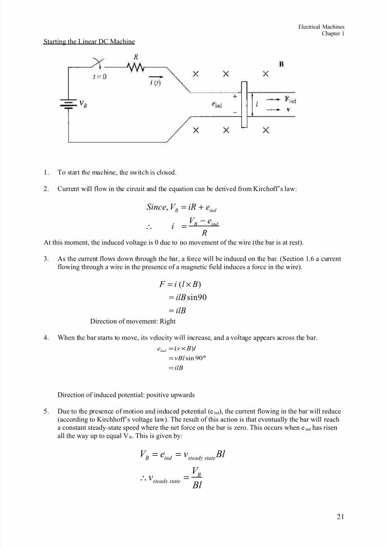
Starting the (inear 2C Machine
1. o start the machine, the s%itch is closed.
*. Current %ill flo% in the circuit and the e!uation can 5e deri+ed from irchoff's la%:
, B ind
B ind
)ince 3 i' e
3 ei
'
= +−
∴ =At this moment, the induced +oltage is J due to no mo+ement of the %ire the 5ar is at rest;.
. As the current flo%s do%n through the 5ar, a force %ill 5e induced on the 5ar. Section 1.8 a currentflo%ing through a %ire in the presence of a magnetic field induces a force in the %ire;.
: ;sinGJ
F i l BilB
ilB
= ×=
=2irection of mo+ement: Right
. "hen the 5ar starts to mo+e, its +elocity %ill increase, and a +oltage appears across the 5ar.
2irection of induced potential: positi+e up%ards
6. 2ue to the presence of motion and induced potential e ind;, the current flo%ing in the 5ar %ill reduceaccording to irchhoff's +oltage la%;. he result of this action is that e+entually the 5ar %ill reach
a constant steady0state speed %here the net force on the 5ar is ero. his occurs %hen e ind has risenall the %ay up to e!ual V B. his is gi+en 5y:
B ind stead! state
B stead! state
3 e v Bl
3 v Bl
= =
∴ =
*1
ilB
vBl
l Bveind
=
°=
×=
GJsin
;:

8/12/2019 EMS by Muneeb Yaqoob
http://slidepdf.com/reader/full/ems-by-muneeb-yaqoob 22/27
Electrical MachinesChapter 1
8. he a5o+e e!uation is true assuming that R is +ery small. he 5ar %ill continue to mo+e along atthis no0load speed fore+er unless some e@ternal force distur5s it. Summari ation of the starting oflinear 2C machine is s#etched in the figure 5elo%:
**
8/12/2019 EMS by Muneeb Yaqoob
http://slidepdf.com/reader/full/ems-by-muneeb-yaqoob 23/27
'
e3 i ind B
↓−↑=
Electrical MachinesChapter 1
he (inear 2C Machine as a Motor
1. Assume the linear machine is initially running at the no0load steady state condition as 5efore;.
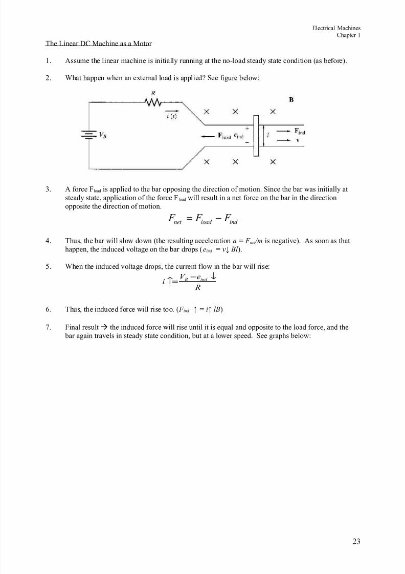
*. "hat happen %hen an e@ternal load is applied9 See figure 5elo%:
. A force ) load is applied to the 5ar opposing the direction of motion. Since the 5ar %as initially at
steady state, application of the force ) load %ill result in a net force on the 5ar in the directionopposite the direction of motion.
net load ind F F F = −
. hus, the 5ar %ill slo% do%n the resulting acceleration a / F net 4m is negati+e;. As soon as thathappen, the induced +oltage on the 5ar drops eind / v5 Bl ;.
6. "hen the induced +oltage drops, the current flo% in the 5ar %ill rise:
8. hus, the induced force %ill rise too. F ind 6 / i6 lB ;
D. )inal result the induced force %ill rise until it is e!ual and opposite to the load force, and the 5ar again tra+els in steady state condition, 5ut at a lo%er speed. See graphs 5elo%:
*

8/12/2019 EMS by Muneeb Yaqoob
http://slidepdf.com/reader/full/ems-by-muneeb-yaqoob 24/27
Electrical MachinesChapter 1
F. &o%, there is an induced force in the direction of motion and po%er is 5eing con+erted fromelectrical to mechanical form to #eep the 5ar mo+ing.
G. he po%er con+erted is P conv / e ind I / F ind v An amount of electric po%er e!ual to eind i isconsumed and is replaced 5y the mechanical po%er F ind v M8T8R
1J. he po%er con+erted in a real rotating motor is: $ con+ Nind O
*

8/12/2019 EMS by Muneeb Yaqoob
http://slidepdf.com/reader/full/ems-by-muneeb-yaqoob 25/27

8/12/2019 EMS by Muneeb Yaqoob
http://slidepdf.com/reader/full/ems-by-muneeb-yaqoob 26/27
" '3 i B
start *6JJ1.J
*6J ===
Electrical MachinesChapter 1
Starting pro5lems %ith the (inear Machine
1. (oo# at the figure here:
*. his machine is supplied 5y a *6JV dc source and internal resistance R is J.1 ohm.
. At starting, the speed of the 5ar is ero, e ind J. he current flo% at start is:
. his current is +ery high 1J@ in e@cess of the rated current;.
6. -o% to pre+ent9 insert an e@tra resistance into the circuit during starting to limit current flo%until e ind 5uilds up enough to limit it, as sho%n here:
*8

8/12/2019 EMS by Muneeb Yaqoob
http://slidepdf.com/reader/full/ems-by-muneeb-yaqoob 27/27
Electrical MachinesChapter 1
E@ample 1.1J
he linear dc machine is as sho%n in a;.
a; "hat is the machine's ma@imum starting current9 "hat is the steady state +elocity atno load9
5; Suppose a J& force pointing to the right %ere applied to the 5ar figure 5;. "hat%ould the steady0state speed 5e9 -o% much po%er %ould the 5ar 5e producing or consuming9-o% much po%er %ould the 5ar 5e producing or consuming9 /s the machine acting as a motor ora generator9
c; &o% suppose a J& force pointing to the left %ere applied to the 5ar figure c;."hat %ould the ne% steady0state speed 5e9 /s the machine a motor or generator no%9