EMPRESA PROPIETARIA DE LA RED, C.A. - …eprsiepac.com/pdf/Volumen-2.pdf · aislamiento, la...
150
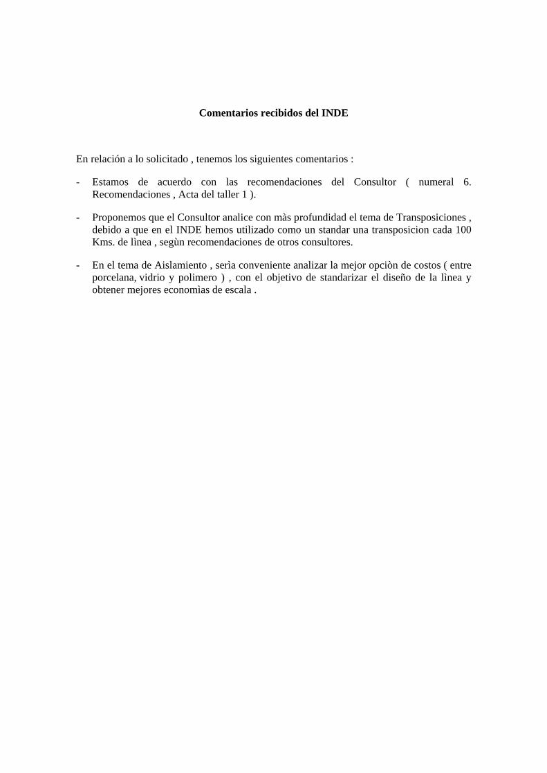
Lago Nicaragua Amarateca Panamá Guate Este Nejapa Cañas Ticuantepe Parrita Aguacaliente Veladero Cajón Río Lindo Panaluya Ahuachapán Planta Nicaragua Guate Norte Palmar Norte Río Claro 15 de Sept. T OMM/EPR Santa Rosa EMPRESA PROPIETARIA DE LA RED, C.A. Definición de los Aspectos Básicos del Diseño de la Línea de Transmisión SIEPAC INFORME FINAL (Vol. II) (ANEXOS 2, 3, 6-9, 27A-30A) Mayo 2004 AB Transmission-Consult Rutherford, NJ, USA
Transcript of EMPRESA PROPIETARIA DE LA RED, C.A. - …eprsiepac.com/pdf/Volumen-2.pdf · aislamiento, la...
Lago
Nicaragua
Amarateca
Panamá
Guate Este
Nejapa
Cañas
Ticuantepe
Parrita
Aguacaliente
Veladero
Cajón Río Lindo
Panaluya
Ahuachapán
Planta Nicaragua
Guate Norte
Palmar Norte Río Claro
15 de Sept.
T
OMM/EPR
Santa Rosa
EMPRESA PROPIETARIA DE LA RED, C.A.
Definición de los Aspectos Básicos del
Diseño de la Línea de Transmisión
SIEPAC
INFORME FINAL (Vol. II)
(ANEXOS 2, 3, 6-9, 27A-30A)
Mayo 2004
AB Transmission-Consult Rutherford, NJ, USA
EMPRESA PROPIETARIA DE LA RED
Definición de los Aspectos Básicos
del
Diseño de la Línea de Transmisión
SIEPAC
Informe Final
Elaborado por: Ing. Amado Beloff Consultor
Mayo 2004
AB Transmission-Consult Rutherford, NJ, USA

ANEXO 2
Cálculos de Ampacidades de Conductores
(Vol. II)


ANEXO 3
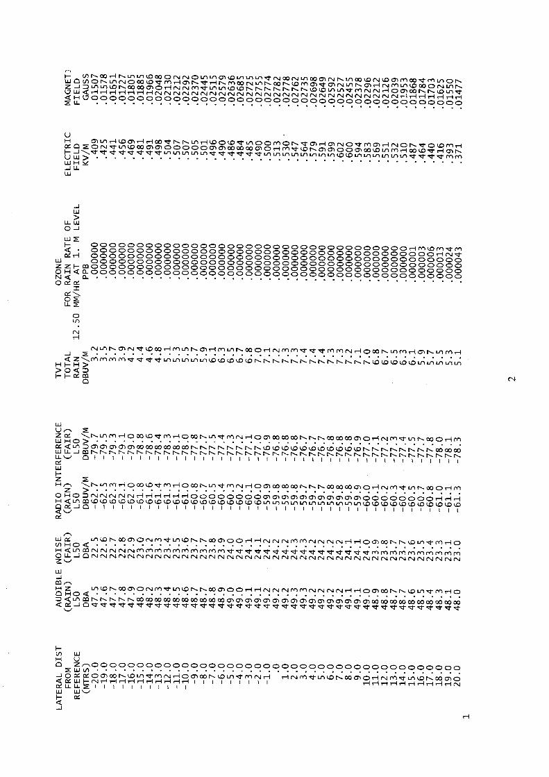
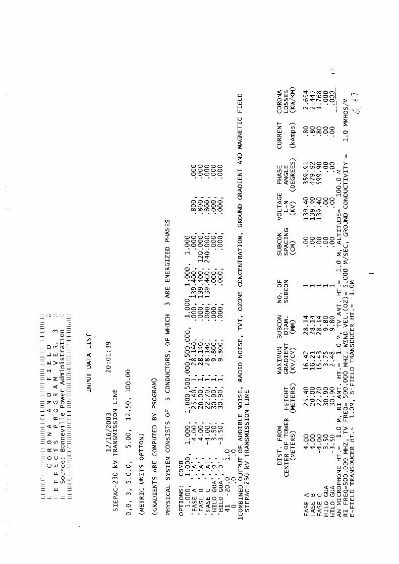
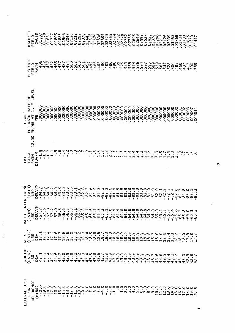
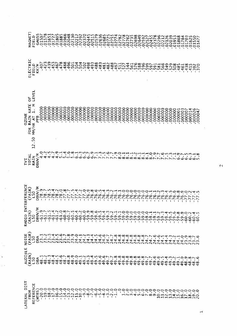
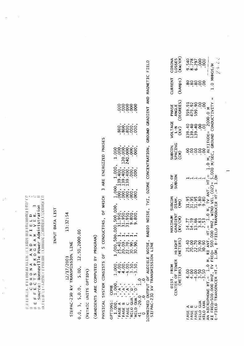
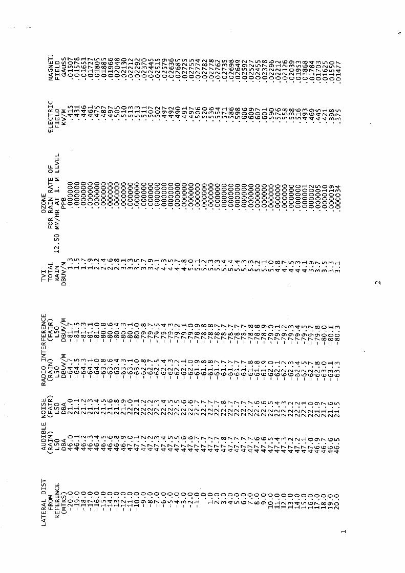
Cálculos de Pérdidas Corona y Efectos Ambientales
(Vol. II)


ANEXO 6
Acta de Reunión del Taller I
(Vol. II)
EMPRESA PROPIETARIA DE LA LINEA EPR
Taller 1 Diseño Básico de la Línea.
San José, Costa Rica, 8 de Enero, 2004 1. ACTO INAUGURAL
El Ing. Francisco Núñez, Gerente General de EPR, dio la bienvenida a los asistentes y menciono que mediante un concurso público internacional se contrató los servicios del consultor individual Ing. Amado Beloff con el objetivo de que, con base en la documentación técnica existente acerca del diseño de la línea de transmisión, realizará los estudios necesarios para revisar y determinar el tipo y calibre del conductor, el tipo y calibre de los hilos de guarda, incluyendo un OPGW, límites de tensiones en los cables, el tipo de aislamiento, la geometría de las estructuras y la familia y alturas de las mismas, el uso de estructuras compactas etc.
2. DISCUSIÓN DE LA AGENDA Previamente se envió vía correo electrónico la agenda a tratar con el consultor Se sometió a consideración la Agenda, la cual fue aprobada y se adjunta como Anexo No. 1.
3. PARTICIPANTES
Durante la reunión se contó con la participación de representantes de todos los socios, representante de la Unidad Ejecutora del Proyecto SIEPAC y del consultor individual. El detalle de los asistentes se adjunta como Anexo No. 2.
4. OBJETIVOS DE LA REUNIÓN.
El objetivo de este taller es conocer los criterios de cada empresa con respecto a los temas en estudio, también intercambiar experiencias que ayuden a completar dicho estudio, y escuchar las opiniones del Consultor, luego de haber efectuado la revisión de los documentos que le fueron entregados, específicamente los informes de DPC, Ingendesa, y estudios de EPR.

5. DESARROLLO DE LA REUNIÓN A. Revisión del Proyecto Preliminar-Introducción
El consultor mencionó que se han revisado los estudios: Diseño Preliminar realizado por Danish Power Consult (DPC), y los otros documentos técnicos generados por INGENDESA y EPR.
B. Requerimientos de transporte. Capacidad térmica del conductor,
parámetros ambientales y geográficos de cálculo para la región. Se discutieron las tablas de Capacidad de Transporte y Características de Conductores presentadas por el Consultor, que se muestra en el Anexo No 3. El Consultor indicó que algunos conductores contemplados en el diseño preliminar de DPC no satisfacen las condiciones de transporte de 300 MW, y propuso secciones mayores.
C. Altitud y efecto corona, parámetros de cálculo. Conductor simple vs. doble.
Ruido Audible (AN), Interferencias de Radio (RI) y televisión (TVI).
Se discutió las Características de los diferentes Conductores, y la necesidad de uno y no dos conductores por fase. El Consultor indicó que para el Proyecto SIEPAC los conductores simples serían suficientes desde el punto de vista de efecto corona y capacidades, y que el uso de 2 conductores por fase elevaría los costos de la línea innecesariamente en un estimado del 20%.
D. Materiales de conductores y contaminación ambiental.
El Consultor comparó las características de conductores ACSR, ACSR/AW y ACAR, y para el proyecto recomendó el uso del conductor ACAR por sus características de menor peso y excelente comportamiento en ambientes contaminados, y características mecánicas, de tensiones y flechas similares al ACSR.
E. Comparación económica de conductores.
En esta parte se presentó la tabla Evaluación Económica del Conductor incluida en los Anexos, que mostró la ventaja económica de los conductores de mayor sección en lo referente a pérdidas y costos anuales de inversión. El representante de El Salvador solicita aclaración sobre la utilización de un solo conductor en contraposición a dos conductores, que es el estándar en
su país. El Consultor manifestó que no serían considerados dos conductores por fase por las razones expuestas en el punto C, y porque los simples satisfacen plenamente y con ventajas los aspectos de operación y costos. El representante de Costa Rica solicitó una sensibilidad con diferentes valores presentados en la tabla. El Consultor concordó en que el estudio de sensibilidad es muy útil y se demostró considerando el valor del costo de Kwh. en 0.06US$ y el costo de la capacidad en 400 US$/kW, valores típicos de la región.
F. Limites de tensión mecánica en conductores ACSR y aluminio. El Consultor indicó que los conductores ACSR y de aluminio pueden trabajar hasta 50% de la carga de ruptura, y para el caso del proyecto no superarán el 35.4%, basado en la utilización de límites EDS de 18% a 25ºC, sin viento final para el ACSR y 16% para el ACAR.
G. Vientos de proyecto. Presión de vientos en conductores y estructuras.
Comparación con proyectos en la región. Impacto económico en el diseño de estructuras.
Se discutió la tabla Comparación de Cargas de Viento, mostrada en el Anexo 3. En la Tabla se mostró la práctica usada en los proyectos de la región, específicamente Guatemala y Costa Rica, que utilizan vientos máximos de 80 KPH y 100-110 KPH, que resultan en presiones de hasta 58 kg/m2 en el conductor y 197 kg/m2 en las torres (sobre estos valores se consideran adicionalmente factores de seguridad). Entre tanto el Informe DPC y los trabajos de Ingendesa resultan en presiones de 106 kg/m2 en los conductores y 338 kg/m2 en las torres, también sin aplicar factores de seguridad. La información adicional recogida de El Salvador para la Interconexión con Honduras indica 48.5 kg/m2 en el conductor y 194 kg/m2 en las torres. El Consultor recomendó bajar las condiciones de proyecto para la línea SIEPAC a valores similares a los utilizados en los diversos países de la Región, y propuso la utilización de un viento máximo de 100 KPH a la altura media de los conductores. El Consultor estimó que el impacto económico en la reducción del viento con respecto a los pesos de las torres y fundaciones sería de un 25% y que podría reducir notablemente los costos del proyecto.
H. Hipótesis de cargas y cargas en las estructuras. Experiencias con caídas de
estructuras y efecto cascada en la región, medidas de seguridad. Propone cambiar las hipótesis de cargas de la siguiente manera:

• Conservar las condiciones de viento máximo pero en el caso de viento transversal agregar una carga por desequilibrio longitudinal simultánea.
• En las cargas de conductor reventado, considerar la rotura de solo uno a la vez y no dos.
• Considerar una hipótesis de construcción y mantenimiento que contempla una carga vertical del doble de vano de peso y un factor de seguridad de 2.
• Considerar una hipótesis de carga de tendido con un factor de seguridad de 2.
• Considerar una hipótesis de desequilibrio longitudinal que considera combinaciones de desbalances longitudinales en las 3 fases, con un factor de seguridad de 1.2.
I. Familia de torres. Torres de ángulo en suspensión vs. anclaje. Altura de
torres. Se presentó un resumen de la familia de torres.
El Consultor indicó que analizará el uso de estructuras compactas para los casos específicos de las salidas de Guate Norte y Guate Este en Guatemala, en casos de franjas de servidumbre estrechas en otros países, y en el caso de aplicación de estructuras estéticas en Costa Rica. En lo que respecta a la familia de torres el Consultor propuso una estructura de ángulo hasta 15 o 20º en suspensión, y una estructura tangente de vanos largos hasta 700-800 m, y que en los vanos superiores a este valor sean vanos aislados con estructuras de amarre del tipo propuesto para ángulos de 30º - 60º, también propuso la combinación de las torres de amarre y ángulo de 30º a 60º y la terminal de 0-45º en una sola torre terminal y ángulos de 0-60º.
J. Transposiciones.
El consultor recomienda que no hay necesidad de utilizar transposiciones dado que los tramos entre subestaciones son relativamente cortos y que la máxima distancia en un tramo es de 234.7 km.
K. Geometría de cabeza de torres, aislamiento, distancias eléctricas. Presentó
unas consideraciones preliminares respecto a las distancias eléctricas.
El Consultor concordó con la utilización de 16 unidades de aisladores cerámicos (porcelana – vidrio) tipo estándar y analizó las distancias propuestas por EPR por sobrecarga de impulso, maniobra y frecuencia industrial, recomendando cambiar la distancia en aire de 2100 mm a 2400 mm en las condiciones de impulso.
L. Aisladores cerámicos y poliméricos, contaminación salina y volcánica.
El consultor recomienda utilizar aisladores poliméricos solo en los tramos ubicados a menos de 10 kilómetros de la costa y en zonas de alta contaminación. (Ej. Ceniza volcánica). Costa Rica recomienda considerar los cuidados en el montaje que se deben tener con aisladores no cerámicos. El resto de la línea utilizaría cadenas de aisladores cerámicos (vidrio o porcelana) como fueron inicialmente propuestos.
M. Materiales de hilos de guardia y OPGW. Capacidad térmica. Corrientes de
corto circuito. Coordinación de flechas con el conductor. Limites de tensión mecánica. Para el hilo de guarda el consultor recomienda el uso del tipo Alumoweld 7 No. 8 en vez de ACSR, basado en el estudio de corrientes de corto circuito realizado por DPC ya que ofrece excelente desempeño en las condiciones de contaminación ambiental. Se recomienda limitar las tensiones del hilo de guarda para obtener una relación de flechas con el conductor entre el 90 y 85% en condiciones normales. Para el cable de guarda tipo OPGW recomendó que sea tipo Alumoweld con las fibras incorporadas en la cantidad recomendada por DPC. (24 fibras).
N. Desempeño de líneas contra descargas atmosféricas. Nivel isoceráunico de
la región. Angulo de blindaje. Resistencia de aterramiento. Experiencias de salidas de líneas en la región.
Varios países indicaron que sufren salidas de líneas frecuentes por descargas atmosféricas, especialmente El Salvador indicó que está instalando pararrayos de líneas para aliviar en parte este problema. El Consultor recomendó bajar la resistencia de torre especificada de 10 ohmios a 5 ohmios, y efectuar cálculos de salidas variando la posición de los hilos de guarda y la resistencia de aterramiento utilizando el programa de EPRI. El Consultor opinó que con relación a la línea SIEPAC deberá determinarse la resistencia de tierra de las torres en base a los estudios de resistividad que realizarán próximamente a lo largo de la línea
O. Otros temas abiertos a discusión.
El Consultor compartió su experiencia en la aplicación de diferentes tipos de fundaciones y opino que no tiene preferencia por algún tipo de fundación en particular pudiéndose usarse fundaciones tipo parrilla (grilla), de zapatas de concreto armado, cilindros de fundación, etc., dependiendo de la disponibilidad de materiales, de los tipos de suelos, de la disponibilidad de mano de obra y de la tecnología a utilizar.

6. RECOMENDACIONES
1. El Consultor presentó los parámetros preliminares del diseño.
o La temperatura ambiente de diseño para la totalidad de la línea: 35 grados centígrados.
o La velocidad del viento para cálculo de la capacidad de transporte: 0,6 m/seg.
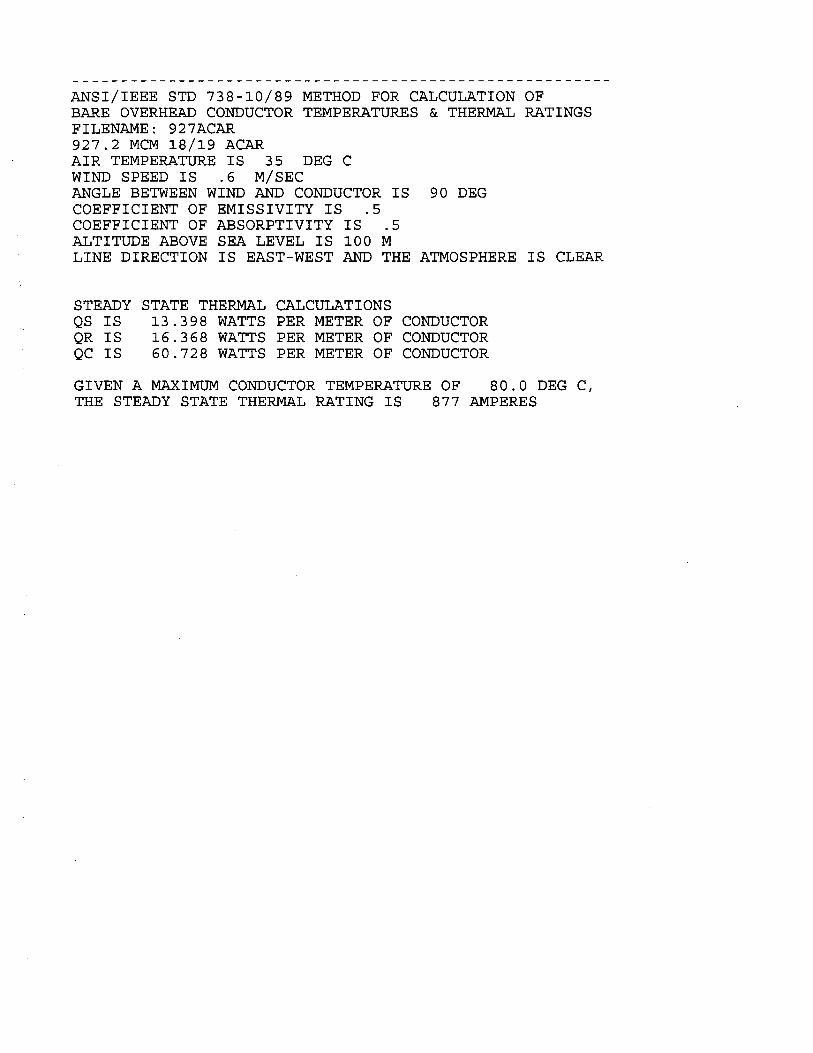
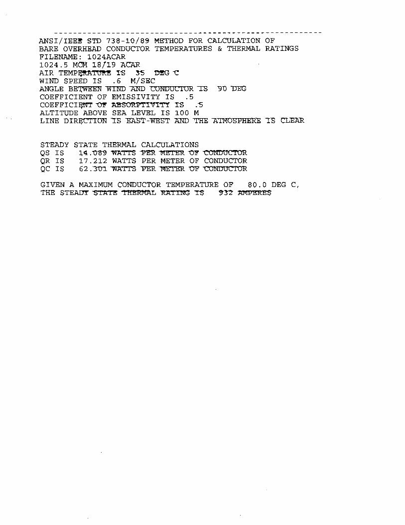
o El conductor para la línea de transmisión: 1024.5 MCM tipo ACAR. o La velocidad de viento para el diseño de las estructuras: 100km/h a
la altura media de los conductores. o Factor de seguridad para las cargas normales: 1.5, 2.0 para cargas
de mantenimiento, y 1.2 para cargas accidentales o excepcionales. o El Consultor definirá la altura de las estructuras, y las familias de
torres. o El cable de guarda recomendado tipo Alumoweld 7N 8. o El cable de guarda OPGW recomendado será tipo Alumoweld con
diámetro similar al otro cable de guarda y conteniendo las 24 fibras. 7. ACUERDOS
1. De parte de los participantes se enviará al Consultor vía correo electrónico las experiencias, sugerencias u observaciones a las presentaciones expuestas en el seminario, también parámetros empleados en cada país para el cálculo de las cargas de viento (presión, velocidades), a más tardar el 15 de enero del 2004.
2. En la preparación del segundo taller el Consultor enviará resultados en
la tercera semana de febrero para lo cual se espera recibir observaciones para ser discutidas durante el desarrollo del taller II.
3. Realizar el siguiente taller para la semana del 8 de marzo del 2004 en
San José con una duración de dos días.
8. CLAUSURA No habiendo otro asunto que tratar se levantó la sesión. Se agradece al ICE por el gran apoyo brindado y la excelente organización para la realización de esta reunión.
ANEXO 7
Comentarios de los Países Miembros del SIEPAC
(Vol. II)

Comentarios recibidos de ETESA
A. VELOCIDADES Y PRESIONES DE VIENTO
Hasta el año 1995 nuestras líneas de transmisión fueron diseñadas tradicionalmente basadas en los requerimientos del NESC. Después de este año, en el diseño de la nueva línea de transmisión de 230 KV que se está construyendo se aceptaron los requerimientos del IEC 826 y CIGRÉ SC22, pero con un poco de reserva, porque estas normas utilizan métodos probabilísticos, que según el período de retorno del viento puede resultar presiones de viento sobre los conductores menores que lo señalado por el NESC.
En Costa Rica usted concluyó que se adoptará para el proyecto una velocidad de viento de 100 km/hr, que representa una presión de viento de 44 kg/m2 y un factor de sobrecarga de 1.5. Lo que me preocupa que esto constituye una presión total de viento de 66 kg/m2 aplicados directamente a los conductores, y que resulta menor a lo utilizado en Panamá (por ETESA), como se podrá aprecia a continuación.
Según el NESC
Velocidad Presión de viento
Viento en la carga máxima (conductores): 97 km/hr (60 mph) 44 kg/m2 (9 lb/pie2)
Viento sobre la torre: 465 kg/m2 (95 lb/pie2)
La presión de viento de 44 kg/m2 se aplicaba directamente a los conductores y aisladores multiplicado por un factor de sobrecarga de 2.5 (Grado B de construcción). Esto da una presión total sobre los conductores de 110 kg/m2.
El viento sobre la torre consistía de una carga de viento transversal o longitudinal, sin conductores ni hilos de guarda, de 6 veces 44 kg/m2 multiplicado por un factor de superficie de 1.6 con una capacidad de sobrecarga de 1.10; esta carga se multiplica 1.0 veces al área proyectada de la cara de una torre. Cabe señalar que este requerimiento de viento sobre la torres obedece a versiones viejas del NESC, pero que fue conservada.
Según IEC 826 y CIGRÉ SC22
Con el propósito de adecuar los datos ambientales disponibles en Panamá a nuestras líneas de transmisión, se utilizaron los registros de datos de viento de que dispone ETESA.. Estos registros de datos de viento corresponden a valores de velocidades máximas de ráfagas de viento (velocidad instantánea) medidos a una altura de 10 metros, para las diversas estaciones meteorológicas existentes en Panamá. Estos datos corresponden a un período comprendido entre 1971 y 1995 y permiten su modelado para el uso con seguridad, dentro de los procedimientos del IEC 826, que recomiendan la existencia de mediciones en el período de, por lo menos, 20 años.

De acuerdo con los criterios del IEC 826, las velocidades de ráfaga pueden ser consideradas dentro de un período de integración de 3 segundos. Para la conversión de estos datos para el período de integración de 10 minutos fue utilizado el gráfico correspondiente indicado por el IEC 826. Con estos valores, es posible entonces, siguiendo los procedimientos del IEC 826, determinar la velocidad de referencia para la línea de transmisión, la cual es 30.0 m/s (108 km/h), considerando un período de retorno de 500 años, y las siguientes presiones de diseño:
Velocidad de Referencia Presión de viento
Viento en la carga máxima: 108 km/hr (30 m/s) Sobre conductores 105 kg/m2 Sobre aisladores 153 kg/m2
Viento sobre la torre No disponible (ver comentario abajo)
La presión de viento se aplica directamente a los conductores multiplicado por un factor de sobrecarga de 1.0; es decir, una presión total sobre los conductores de 105 kg/m2, valor similar al calculado por medio del NESC.
Con respecto al viento sobre las torres, no disponemos de un valor de presión porque de acuerdo con el IEC 826 las torres deben ser divididas en diversos paneles, siendo la fuerza calculada sobre cada uno de ellos individualmente de acuerdo con una fórmula de la IEC 826. Este cálculo de viento lo hace el diseñador del fabricante de las torres. ¿existe alguna manera, como lo hace el NESC, de poder especificar una presión de viento para la torre?
SISTEMA DE PUESTA A TIERRA
En Panamá el nivel isoceráunico es alto, de tal forma que a la fecha estamos utilizando para los cálculos el valor de 150. Además, consideramos una resistividad del suelo de 1000 ohmios-m. y hasta la fecha hemos utilizado una resistencia máxima de tierra de 20 ohmios. Este valor lo vamos a revisar, por la cantidad de rayos que caen en la Provincia de Chiriquí, lugar donde se construirá el tramo de la línea del SIEPAC.
Para cada torre utilizamos un sistema de puesta a tierra radial básico (“crowfoot”): Desde cada pata se extiende un conductor de compensación (“counterpoise”) de 30 metros de longitud, consistente y las cuatro patas se interconectan. Se utiliza un conductor copperweld 3#6 Awg. Antes de 1995 se instalaba una varilla de tierra en cada extremo de cada conductor radial; ahora, se eliminó.
Comentarios recibidos del INDE
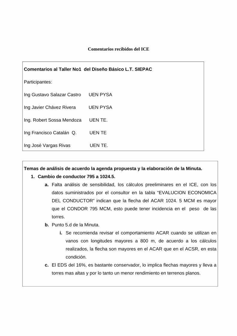
En relación a lo solicitado , tenemos los siguientes comentarios :
- Estamos de acuerdo con las recomendaciones del Consultor ( numeral 6. Recomendaciones , Acta del taller 1 ).
- Proponemos que el Consultor analice con màs profundidad el tema de Transposiciones , debido a que en el INDE hemos utilizado como un standar una transposicion cada 100 Kms. de lìnea , segùn recomendaciones de otros consultores.
- En el tema de Aislamiento , serìa conveniente analizar la mejor opciòn de costos ( entre porcelana, vidrio y polimero ) , con el objetivo de standarizar el diseño de la lìnea y obtener mejores economìas de escala .
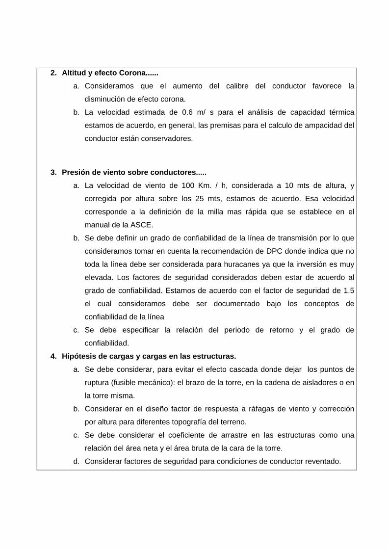
Comentarios recibidos del ICE
Comentarios al Taller No1 del Diseño Básico L.T. SIEPAC
Participantes:
Ing Gustavo Salazar Castro UEN PYSA
Ing Javier Chávez Rivera UEN PYSA
Ing. Robert Sossa Mendoza UEN TE.
Ing Francisco Catalán Q. UEN TE
Ing José Vargas Rivas UEN TE.
Temas de análisis de acuerdo la agenda propuesta y la elaboración de la Minuta. 1. Cambio de conductor 795 a 1024.5.
a. Falta análisis de sensibilidad, los cálculos preeliminares en el ICE, con los
datos suministrados por el consultor en la tabla “EVALUCION ECONOMICA
DEL CONDUCTOR” indican que la flecha del ACAR 1024. 5 MCM es mayor
que el CONDOR 795 MCM, esto puede tener incidencia en el peso de las
torres. b. Punto 5.d de la Minuta.
i. Se recomienda revisar el comportamiento ACAR cuando se utilizan en
vanos con longitudes mayores a 800 m, de acuerdo a los cálculos
realizados, la flecha son mayores en el ACAR que en el ACSR, en esta
condición. c. El EDS del 16%, es bastante conservador, lo implica flechas mayores y lleva a
torres mas altas y por lo tanto un menor rendimiento en terrenos planos.
2. Altitud y efecto Corona...... a. Consideramos que el aumento del calibre del conductor favorece la
disminución de efecto corona.
b. La velocidad estimada de 0.6 m/ s para el análisis de capacidad térmica
estamos de acuerdo, en general, las premisas para el calculo de ampacidad del
conductor están conservadores.
3. Presión de viento sobre conductores..... a. La velocidad de viento de 100 Km. / h, considerada a 10 mts de altura, y
corregida por altura sobre los 25 mts, estamos de acuerdo. Esa velocidad
corresponde a la definición de la milla mas rápida que se establece en el
manual de la ASCE.
b. Se debe definir un grado de confiabilidad de la línea de transmisión por lo que
consideramos tomar en cuenta la recomendación de DPC donde indica que no
toda la línea debe ser considerada para huracanes ya que la inversión es muy
elevada. Los factores de seguridad considerados deben estar de acuerdo al
grado de confiabilidad. Estamos de acuerdo con el factor de seguridad de 1.5
el cual consideramos debe ser documentado bajo los conceptos de
confiabilidad de la línea
c. Se debe especificar la relación del periodo de retorno y el grado de
confiabilidad.
4. Hipótesis de cargas y cargas en las estructuras. a. Se debe considerar, para evitar el efecto cascada donde dejar los puntos de
ruptura (fusible mecánico): el brazo de la torre, en la cadena de aisladores o en
la torre misma.
b. Considerar en el diseño factor de respuesta a ráfagas de viento y corrección
por altura para diferentes topografía del terreno.
c. Se debe considerar el coeficiente de arrastre en las estructuras como una
relación del área neta y el área bruta de la cara de la torre.
d. Considerar factores de seguridad para condiciones de conductor reventado.
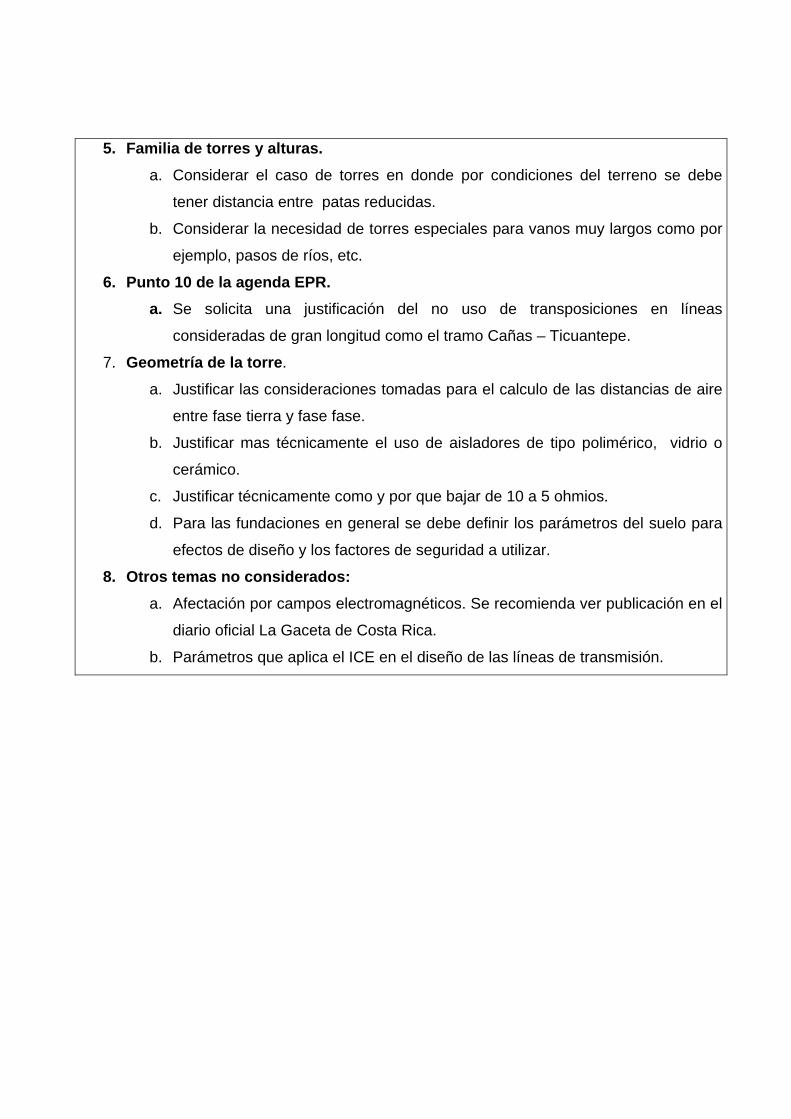
5. Familia de torres y alturas. a. Considerar el caso de torres en donde por condiciones del terreno se debe
tener distancia entre patas reducidas.
b. Considerar la necesidad de torres especiales para vanos muy largos como por
ejemplo, pasos de ríos, etc.
6. Punto 10 de la agenda EPR. a. Se solicita una justificación del no uso de transposiciones en líneas
consideradas de gran longitud como el tramo Cañas – Ticuantepe. 7. Geometría de la torre.
a. Justificar las consideraciones tomadas para el calculo de las distancias de aire
entre fase tierra y fase fase.
b. Justificar mas técnicamente el uso de aisladores de tipo polimérico, vidrio o
cerámico.
c. Justificar técnicamente como y por que bajar de 10 a 5 ohmios.
d. Para las fundaciones en general se debe definir los parámetros del suelo para
efectos de diseño y los factores de seguridad a utilizar.
8. Otros temas no considerados: a. Afectación por campos electromagnéticos. Se recomienda ver publicación en el
diario oficial La Gaceta de Costa Rica.
b. Parámetros que aplica el ICE en el diseño de las líneas de transmisión.
Comentarios recibidos de ETESAL
1.- CONDUCTOR Y CABLE DE GUARDA
a) Para la determinación del conductor, el Consultor deberá presentar la evaluación
técnica y económica, con su respectiva memoria de cálculo, incluyendo en su análisis dos conductores por fase Flicker 477 MCM, ya que este tipo de conductor es utilizado en El Salvador y Honduras, a fin de que la opción sugerida este debidamente documentada.
b) El Consultor deberá incluir en la memoria de cálculo los parámetros considerados
para la evaluación de las pérdidas por efecto corona en la línea, asunción de costos de materiales e inversiones, etc. Así como el catálogo del conductor que resultare propuesto, en el que se incluya datos eléctricos y mecánicos.
c) El Consultor deberá indicar para la determinación del conductor, las consideraciones que utilizó respecto a los valores de sobrecorrientes y corrientes de corto circuito.
d) Para el cable de guarda propuesto el Consultor deberá indicar cuales fueron los valores de corrientes considerados tanto para cortocircuito como para protección frente a descargas atmosféricas y presentar el cálculo de blindaje del cable de guarda. Asimismo, presentar la memoria de cálculo que llevó a determinar que el cable de guarda propuesto es la mejor opción técnica y económica, respecto de otras opciones.
2. - ESTRUCTURAS
2.1- Hipótesis de Cargas en las Torres
En las hipótesis de carga, para el diseño de las torres, en las cargas de conductor roto, el Consultor deberá considerar la ruptura de un cable de guarda y una fase por cada circuito.

El Consultor deberá presentar las consideraciones técnicas para la definición de los factores de seguridad en el diseño de la torres.
2.2 Torres
El Consultor deberá definir la geometría de la familia de estructuras para 1, 2 y 4 circuitos a emplear en la línea de transmisión (alturas, tipos de torres y longitud de patas). Asimismo, deberá presentar los vanos de viento, vano de peso y vano máximo que se utilizarán para el diseño de las diferentes torres e incluir las consideraciones realizadas para la determinación de dichos vanos ( con su respectivo vano gobernante).
El Consultor deberá determinar el vano económico a utilizar y la altura básica de las diferentes estructuras.
Para los vanos de peso y viento sugeridos, las torres de anclaje no podrían utilizar vanos de gran longitud, lo que podría causar inconveniente en el diseño de la línea, debido a que la mayor parte del terreno en El Salvador es montañoso.
El Consultor deberá presentar las consideraciones y cálculos realizadas para la definición de los límites a utilizarse respecto a las tensiones mecánicas del conductor y cable de guarda.
3.- AISLADORES
a) El consultor deberá recomendar el tipo de aislador a utilizar con base a costos y a condiciones de operación.
4.- PUESTA A TIERRA
a) El Consultor deberá definir el tipo de puesta a tierra, especificando las características de varilla, cable conectores y demás accesorios y sus respectivas normas. Además, deberá presentar la metodología para la instalación de la puesta a tierra en caso de no conseguir la resistencia requerida.
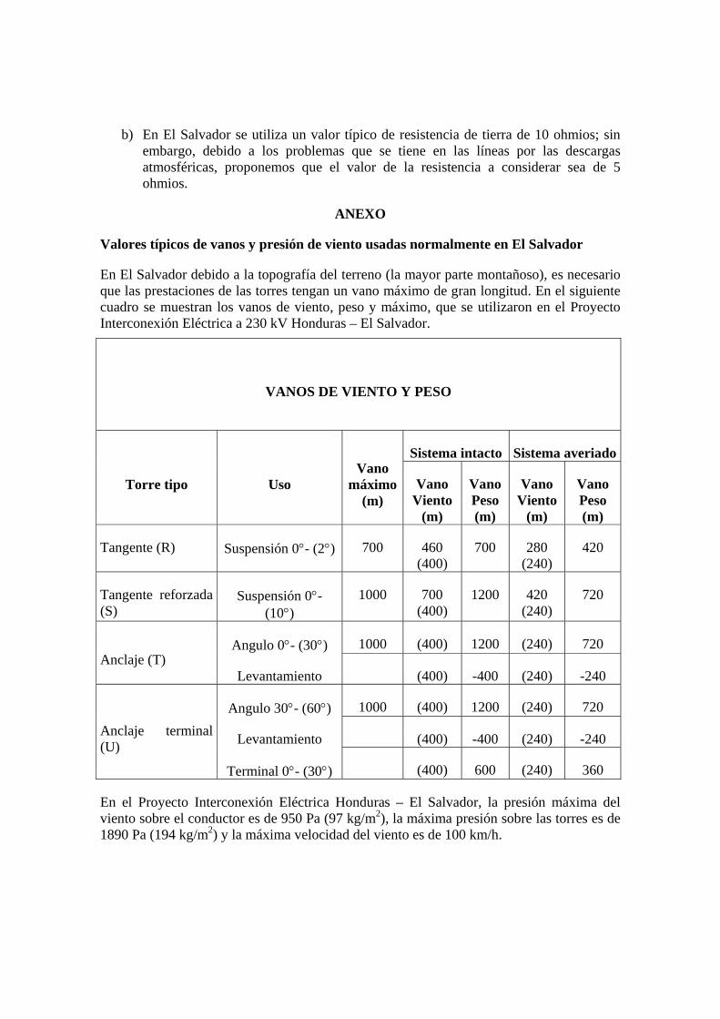
b) En El Salvador se utiliza un valor típico de resistencia de tierra de 10 ohmios; sin embargo, debido a los problemas que se tiene en las líneas por las descargas atmosféricas, proponemos que el valor de la resistencia a considerar sea de 5 ohmios.
ANEXO
Valores típicos de vanos y presión de viento usadas normalmente en El Salvador
En El Salvador debido a la topografía del terreno (la mayor parte montañoso), es necesario que las prestaciones de las torres tengan un vano máximo de gran longitud. En el siguiente cuadro se muestran los vanos de viento, peso y máximo, que se utilizaron en el Proyecto Interconexión Eléctrica a 230 kV Honduras – El Salvador.
VANOS DE VIENTO Y PESO
Sistema intacto Sistema averiado
Torre tipo Uso Vano
máximo (m)
Vano Viento
(m)
Vano Peso (m)
Vano Viento
(m)
Vano Peso (m)
Tangente (R) Suspensión 0°- (2°) 700 460 (400)
700 280 (240)
420
Tangente reforzada (S)
Suspensión 0°- (10°)
1000 700 (400)
1200 420 (240)
720
Angulo 0°- (30°) 1000 (400) 1200 (240) 720 Anclaje (T)
Levantamiento (400) -400 (240) -240
Angulo 30°- (60°) 1000 (400) 1200 (240) 720
Levantamiento (400) -400 (240) -240 Anclaje terminal (U)
Terminal 0°- (30°) (400) 600 (240) 360
En el Proyecto Interconexión Eléctrica Honduras – El Salvador, la presión máxima del viento sobre el conductor es de 950 Pa (97 kg/m2), la máxima presión sobre las torres es de 1890 Pa (194 kg/m2) y la máxima velocidad del viento es de 100 km/h.
Comentarios recibidos de ENTRESA
En ENTRESA utilizamos para diseño de línea de transmisión una velocidad de viento de 120 kms/hora y una presión de 60 Kg/m2 y una resistencia de 10 ohmio. Te aclaramos que el tramo entre la frontera de honduras y la planta nicaragua es de 120 kms. es de alto nivel de descargas atmosféricas.
Comentarios recibidos de la Unidad Ejecutora de SIEPAC
San José, 13 de enero de 2003
Ezequiel Galdamez
Gerente Técnico de la EPR
Presente.
Estimado Señor:
Con respecto a los conceptos vertidos en el Taller No 1 del Diseño Básico de la Línea SIEPAC, la Unidad Ejecutora tiene los siguientes comentarios y/o observaciones acerca de la selección del conductor:
Es importante mencionar que el requerimiento básico del Proyecto SIEPAC es que se puedan intercambiar por lo menos 300 Mw entre pares de países. La Línea SIEPAC, junto con los sistemas nacionales existentes y las interconexiones actuales, permitirá realizar este objetivo. Debido al hecho de que la Línea SIEPAC se interconectara en 16 puntos del Sistema Eléctrico Regional Centroamericano, estará en paralelo con el mismo y cuando se estén intercambiando 300 Mw entre pares de países, la Línea SIEPAC llevara aproximadamente 150 Mw. Solamente en condiciones de emergencia, cuando exista una contingencia simple en líneas paralelas a la Línea SIEPAC, esta será exigida para transportar los 300 Mw. El caso del tramo Guate Norte – Panaluya - Río Lindo será respaldado por los sistemas eléctricos de Honduras y El Salvador.
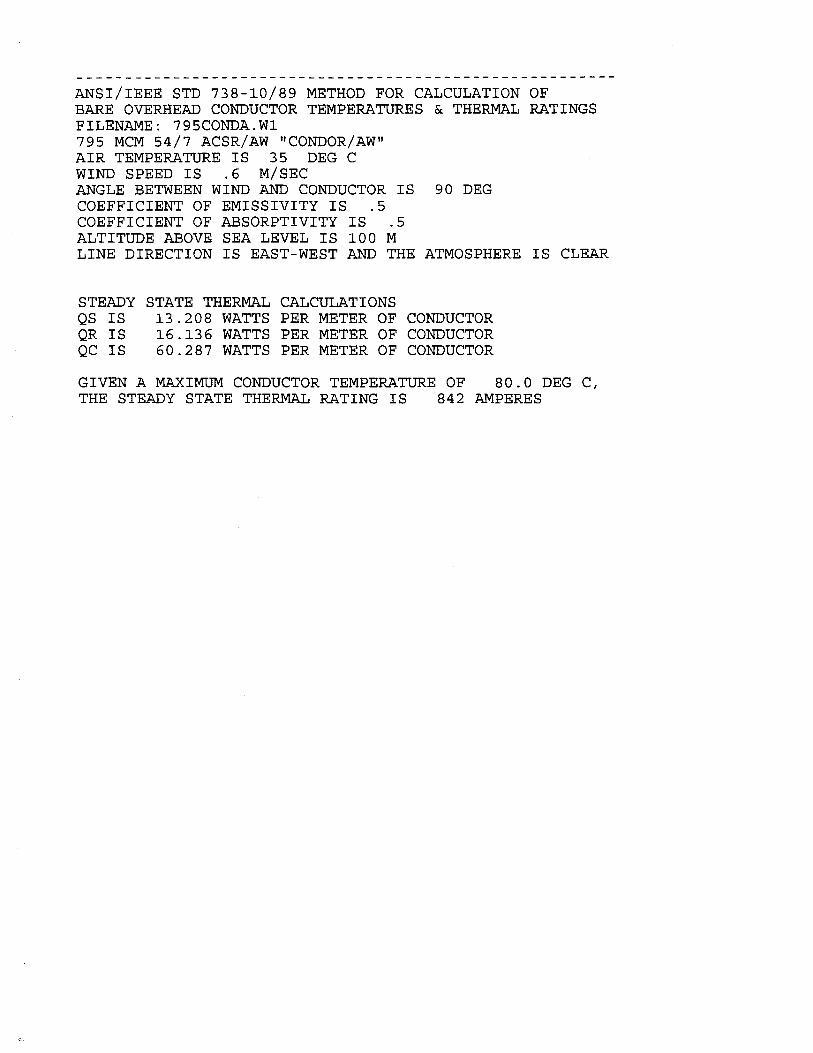
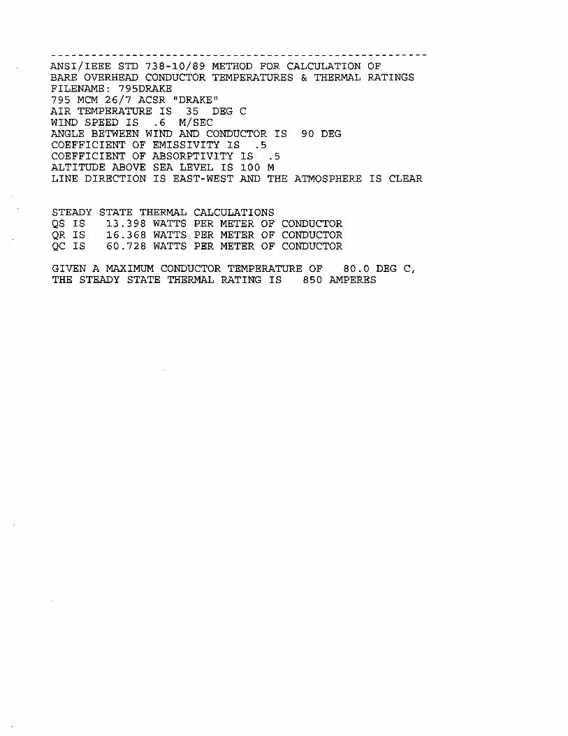
El Consultor DPC recomendó que la ampacidad necesaria del conductor debería estar en el rango de 750 a 800 amperios (Ver Numeral 9.4.3) . Basado en una temperatura máxima del conductor de 80 °C, radiación solar de 1,000 w/m², temperatura ambiente de 40 °C, 200 metros sobre el nivel del mar y una velocidad del viento de 0.6 m/s, el Consultor DPC calculo una ampacidad de 766 amperios para el conductor Condor. (Ver Numeral 9.4).
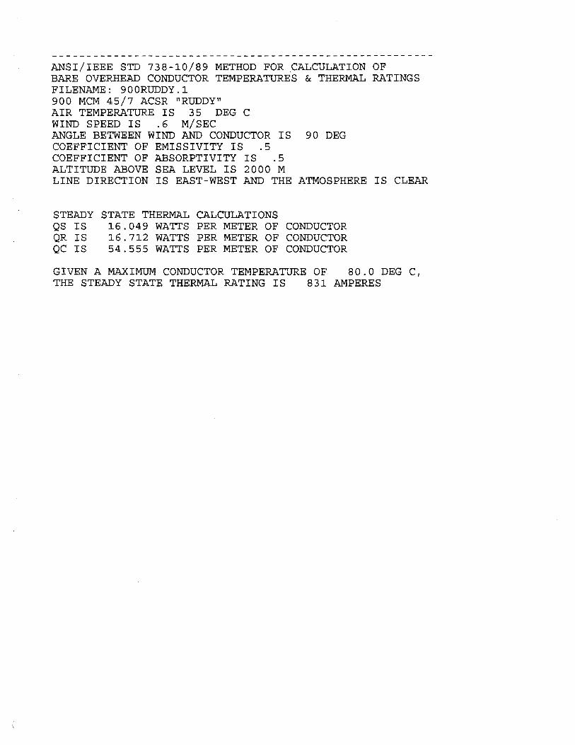
Utilizando otros parámetros, el Consultor Beloff calcula que la ampacidad del Condor es de 831 amperios a 100 metros sobre el nivel del mar (8.5% mayor que la calculada por DPC). También calculo que la ampacidad del conductor Condor a 2,000 metros sobre el nivel del mar era de 770 amperios.
De acuerdo a los datos del Consultor Beloff, el conductor Condor se sobrecargaría 0.7% a 100 metros y 8.7% a 2000 metros si hubiera una contingencia de las líneas paralelas a la Línea SIEPAC y se le exigiera a la Línea SIEPAC transportar 300 Mw (837 amperios @ 0.9 pf).
Favor solicitarle al Consultor Beloff: a) Explique cuales son los criterios de sobrecarga que deberían de usarse para el diseño de la
Línea SIEPAC y cuanto tiempo debería permitirse la sobrecarga b) Explicar porque es mejor utilizar la temperatura ambiente de 35 °C en vez de 40 °C que uso
DPC c) Aclarar si el criterio de usar 1000 w/ m² es equivalente a usar el criterio de la latitud de 12.5
grados
En el análisis económico, el Consultor Beloff considera elegibles a los Conductores Ruddy, Rail y 1024 ACAR. El más económico desde el punto de vista de costos totales anuales es el Rail AW y considerando que la EPR no percibiría la disminución de perdidas sino que únicamente haría frente a los sobrecostos de inversión, el más económico desde el punto de vista de la EPR es el Ruddy. Además, el Consultor Beloff ha considerado que la línea estaría cargada a 300 Mw y como mencionamos anteriormente esto solo ocurriría en situaciones de contingencia.
Favor solicitarle al Consultor Beloff: a) Considere un transporte de 150 Mw como la carga máxima en operación normal en la
evaluación económica. b) Presente el monto en dólares de sobrecosto de inversión para la EPR por escoger
conductores de mayor calibre
Finalmente, deseo reiterarle la disposición de todos los órganos del Proyecto SIEPAC a colaborar con la EPR en el desarrollo de la Línea SIEPAC.
Sin otro particular por el momento, le saluda atentamente,
Edgardo Alfredo Calderón

ANEXO 8
Respuestas del Consultor
(Vol. II)
Respuesta a comentarios de Panamá
1. VELOCIDADES Y PRESIONES DE VIENTO Efectivamente la velocidad de viento propuesto a la altura de los conductores es de 100 km/h lo que corresponde a una presión de 48 kg/m2 que, aplicando un factor de sobrecarga 1.50, resulta en una presión final de 72 kg/m2. Actualmente Panamá diseña sus líneas con una presión final de 105 kg/m2 sobre los conductores, esto se traduciría en aproximadamente 105/72=45% mas de presión que lo propuesto lo que resultaría en un sobrepeso de acero de 15-20% o aproximadamente 3 toneladas más por km (15% de 20 t/km), o un total de 3 t/km x 1830 km = 5500 toneladas que al precio de $2,500 por tonelada (material y montaje) nos daría una sobre inversión en exceso de $12,000,000, sin contar con el costo extra de las fundaciones. Aparentemente la presión escogida de 105 kg/m2 fue derivada como consecuencia de mantener los valores anteriores que históricamente utilizaron, esto es, por la aplicación de las prescripciones mínimas de viento de la NESC para las regiones sin hielo en USA, o sea 9 lb/ft2 (44 kg/m2) con factor de carga transversal 2.50. Conviene subrayar que esta presión corresponde a una velocidad de viento de casi 100 km/h al que se le ha asignado un factor de carga sumamente elevado no consubstanciado con las experiencias de otros países en CA. Llama la atención que la aplicación lisa y rasa de las prescripciones de la NESC no tuvieron validación efectiva a través de la investigación de vientos en la región, cuya justificación ahora es que la velocidad de viento adoptado (siguiendo la metodología IEC 826 a la inversa) es de 30 m/s (108 km/h) considerando un periodo de retorno de 500 años. La línea SIEPAC no justificaría ser diseñada para un periodo de retorno de 500 años y tampoco para un período de retorno de 150 años como fue propuesto en el informe DPC. De ahí que la conclusión de adoptar un viento de 100 km/h directamente sobre el conductor aparece económicamente y técnicamente correcta si se compara con las propias experiencias de dos países tan alejados como Guatemala y Costa Rica que diseñan sus líneas para 100 km/h y 80 km/h, respectivamente con factores de carga alrededor de 1.50, con excelente experiencia operacional. También El Salvador diseña para un viento máximo de 100 km/h directo en los conductores. 2. PRESION DE VIENTO SOBRE LAS TORRES El representante de Panamá no dispone de un valor de presión de viento aplicada en sus estructuras ya que calculan el mismo individualmente para cada panel de la torre de acuerdo con una formula de la IEC 826. Este es un procedimiento laborioso de gran complejidad, muy exacto pero que exige de gran atención y cuidado al proyectista y dificulta la tarea del ingeniero revisor, es inclusive difícil de duplicar en los modelos de pruebas a escala natural en las estaciones de ensayo de los fabricante de estructuras.
Un ejercicio de tal precisión es innecesario y me remito a las recomendaciones del ASCE-74 donde claramente se establece que para torres hasta 200 ft (65 m) de altura es suficiente especificar una única presión de viento calculada a la altura del centro de gravedad de la estructura o a 2/3 de la altura total de la misma. La presión resultante así calculada es aplicada a toda la extensión de la torre y con esto se obtiene un solo e inequívoco parámetro de velocidad y presión de viento. En USA se utiliza un único valor de presión de viento en la estructura. Aclaro que solo en estructuras muy elevadas como podrían ser las grandes travesías de ríos de llanura (caso de las travesías del río Mississippi en USA) con alturas de hasta 200 m se aplican velocidades y presiones corregidas por altura a partir de los 60 m. 3. SISTEMA DE PUESTA A TIERRA El nivel isoceraunico de 150 tormentas por año es extraordinariamente elevado. También el valor de resistividad de suelos de 1000 ohm.m es muy alto y extraño para una región de cultivos como es la zona del Chiriquí. Es evidente que si así fuera deberían tomarse medidas para bajar artificialmente la resistividad de suelos a fin de conseguir resistencias inferiores a 20 ohms. La utilización de contrapeso radial en áreas de alta resistividad es la indicada y también debería estudiarse la aplicación de ángulo de blindaje negativo en las torres. De todas maneras es aconsejable comenzar con un programa de investigación de resistividad de suelos para obtener el perfil de resistividad a diferentes profundidades.
Respuesta a los comentarios de Guatemala
1 TRANSPOSICIONES En la actualidad, con los sistemas en expansión y más líneas llegando a los nodos del sistema interconectado (subestaciones), es difícil concluir en la necesidad de transposiciones para distancias de 100 km. En los sistemas de transmisión se acepta un cierto grado de desbalance en las reactancias e impedancias mutuas de cada fase, esta es una condición que depende en gran parte de la configuración de conductores. Para la línea SIEPAC, mayormente configurada en triángulo para las secciones de circuito simple el desbalance de fases es menor aún. Longitudes de líneas de hasta 200 millas (320 km) no llevan transposiciones de línea en USA. La línea SIEPAC es altamente seccionada y no se recomienda el uso de transposiciones. Por otra parte es bueno resaltar que las transposiciones son puntos débiles de la línea en cuanto están sujetas a mayor número de salidas por descargas atmosféricas que las geometrías normales.
2 AISLADORES Me remito a la respuesta dada a los comentarios de El Salvador. “El tema de aisladores fue abordado y concluido por el deseo de los países de no utilizar en general materiales poliméricos por posibles problemas de maltrato y daño durante la construcción. Solo restan los materiales cerámicos, vidrio y/o porcelana indistintamente sobre los cuales no tengo preferencia, ambos son igualmente eficientes y esto debería dejarse al criterio y economía de los contratistas, o de lo contrario a la propia experiencia y preferencia de los países del SIEPAC. Trechos específicos de la línea que requieran un alto índice de distancia de fuga en zonas de contaminación salina y volcánica serán diseñados con aisladores poliméricos cuyo desempeño es notoriamente superior a los aisladores cerámicos”. Las economías de escala serán evaluadas durante el análisis de las propuestas de los contratistas. Ellos seleccionaran en sus propuestas las opciones más económicas conforme especificaciones de EPR.
Respuesta a los comentarios de Costa Rica
1. CONDUCTOR Los cálculos del consultor no avalan las conclusiones de Costa Rica referentes a las flechas mayores encontradas para el conductor 1024 ACAR comparadas con ACSR. El conductor propuesto tiene formación 18/19 y aparentemente Costa Rica utilizó una formación con menor RTS. Favor verificar. La tensión EDS 16% para el ACAR es estándar en la industria en USA y tiene bases en las recomendaciones del CIGRE, IEEE, fabricantes de conductores (ALCOA, ALCAN) y muchos años de aplicación exitosa. 2. ALTITUD Y EFECTO CORONA Nada nuevo. 3. PRESION DE VIENTO SOBRE LOS CONDUCTORES Erróneamente se ha interpretado que la velocidad de viento propuesta es de 100 km/h considerada a la altura de 10 m y corregida por altura sobre los 25 m. Esta fue la propuesta del informe DCP que el consultor desestimó ya que llevaría a diseñar torres y fundaciones extremadamente costosas, como fue demostrado en el Taller I, y que no corresponden a la práctica adoptada por el ICE que aplica un viento máximo de 80 km/h a la altura de los conductores sin corrección alguna, ni de otros países como Guatemala y El Salvador que aplican vientos de 100 km/h directamente a la altura de los conductores.
El factor de carga 1.50 recomendado por DPC es el adoptado para la línea SIEPAC y ya fue documentado en el informe DPC, sin cambios.
4. HIPOTESIS DE CARGAS Y CARGAS EN LAS ESTRUCTURAS El informe DPC y el consultor no mencionan el concepto de fusible. No habrá “fusible mecánico” en esta línea. Tal práctica es desaconsejable. La torre y los aisladores tendrán las mismas cargas de diseño y confiabilidad. No serán considerados factores de respuesta a ráfagas de viento diferentes para topografías diferentes. La pregunta es académica y no se recomienda en el informe DPC ni por el consultor. Las complicaciones innecesarias y académicas son descartadas en el diseño de la línea SIEPAC. 5. FAMILIA DE TORRES Y ALTURAS Nada nuevo. 6. TRANSPOSICIONES Las justificativas para el uso de transposiciones en el tramo mas largo (234 km) deben provenir de los estudios de comportamiento del sistema (estudios de flujos de carga), o de los criterios de desbalance de fases de las propias compañías integrantes del SIEPAC. Nuestra recomendación ha sido no usar transposiciones por no ser la línea suficientemente larga para que provoque un desbalance importante entre las fases. Por otra parte es bueno resaltar que las transposiciones son puntos débiles de la línea en cuanto están sujetas a mayor número de salidas por descargas atmosféricas que las geometrías normales. 7. GEOMETRIA DE LA TORRE En el Taller 1 fue recomendada la utilización de aisladores cerámicos (vidrio o porcelana indistintamente) debido a objeciones en la utilización de materiales no-cerámicos por posible maltrato y daño durante la construcción. Estos tipos de aisladores cerámicos no precisan de justificación ya que operan satisfactoriamente en áreas de bajo nivel de contaminación como demuestra la extensa experiencia de los 6 países de CA y en otras partes del mundo, por décadas. Solamente secciones altamente contaminadas situadas en las zonas costeras (contaminación salina) y zonas de contaminación volcánica utilizaran aisladores no-cerámicos por su elevado índice de distancia de fuga, excelentes características de hidrofobicidad y desempeño superior en ambientes contaminados comparados con los aisladores cerámicos. Con relación al desempeño previsto de la línea contra descargas atmosféricas se están realizando cálculos para determinar la efectividad de bajar la resistencia de tierra de
10 a 5 ohms. El diseño de la puesta a tierra no esta incluído en el alcance del consultor. La definición de parámetros de suelos para el diseño de fundaciones no esta incluído en el alcance del consultor. 8. OTROS TEMAS NO CONSIDERADOS El estudio de los efectos electromagnéticos en el medio ambiente generados por la línea no está incluído en el alcance del consultor. Se desconoce cualquier publicación aludida en el diario oficial La Gaceta de Costa Rica.
Respecto de los parámetros que aplica el ICE en el diseño de las líneas de transmisión estos deben ser sometidos a apreciación del consultor. Sin embargo este no se constituye en tema de discusión sino que sería meramente informativo.
Respuesta de comentarios de El Salvador
1. CONDUCTOR Y CABLE DE GUARDIA Como ya fue indicado el uso de dos conductores por fase es considerablemente más oneroso (15-20%) que una línea de conductor simple para una misma capacidad de transporte. El uso de conductor doble atentaría contra el criterio de mínima inversión que se indica en el informe DPC. Efectivamente dos conductores Flicker ofrecen una sección transversal de conductor 2x0.846”/1.165”= 1.45 veces mayor de área expuesta al viento y también una tensión máxima de ruptura de 2x17,200/26,700 = 1.29 veces mayor lo que hace que las estructuras sean mas pesadas en un 20 % sin considerar el impacto económico de las fundaciones. El informe DPC descartó el uso de dos conductores por fase y seria un ejercicio fútil considerar esta opción en el estudio económico de conductores cuando por el contrario la Unidad Ejecutora SIEPAC esta procurando medios de minimizar la inversión inclusive cuestionando el uso de conductores de mayor diámetro que el Cóndor. 2. ESTRUCTURAS La familia de torres propuesta considera las posibilidades de salvar vanos de hasta 700 m con estructuras de suspensión y vanos entre 700 y 1000 m con estructuras de amarre. Si hubiera vanos superiores deberían ser comunicados inmediatamente. De todas maneras no se entiende porque las estructuras de anclaje con vanos largos no podrían utilizarse en la región montañosa (siempre se podrán utilizar helicópteros si fuera necesario y económico). El cuadro que muestra las prestaciones de vanos para la interconexión Honduras-El Salvador es bien significativo y esta muy de acuerdo con la familia de torres propuesta para la línea SIEPAC
Los factores de seguridad serán los propuestos en el informe DPC con una modificación en los mismos para hipótesis de mantenimiento y tendido, es 1.50 para cargas normales, 1.2 para cargas excepcionales y 2.0 para cargas de mantenimiento y construcción. Estos son factores normalmente utilizados por la industria y los países del SIEPAC y no merecen mayor demostración. El vano económico es un término meramente académico y no es objeto de estudio en esta línea a menos que se desee realizar un análisis detallado de optimización con programas digitales existentes (EPRI, PTI), que están fuera del alcance de este contrato. Todo lo que se puede establecer es el vano medio deseado para esta línea, basado en experiencia, que ya fue definido en el informe DPC en torno de 380 m al que no le encuentro inconveniente. 3. AISLADORES El tema de aisladores fue abordado y concluido por el deseo de los países de no utilizar en general materiales poliméricos por posibles problemas de maltrato y daño durante la construcción. Solo restan los materiales cerámicos, vidrio y/o porcelana indistintamente sobre los cuales no tengo preferencia, ambos son igualmente eficientes y esto debería dejarse al criterio y economía de los contratistas, o de lo contrario a la propia experiencia y preferencia de los países del SIEPAC. Trechos específicos de la línea que requieran un elevado índice de distancia de fuga en zonas de contaminación salina y volcánica, serán diseñados con aisladores poliméricos, notoriamente más eficientes que los aisladores cerámicos. 4. PUESTA A TIERRA El tema no esta incluido en las tareas del Consultor. Sin embargo estoy de acuerdo con el temperamento de especificar resistencias bajas de pie de torre debido a la gran actividad atmosférica en la región que necesitará de todos los métodos posibles de mitigación de los efectos indeseables de las descargas en el desempeño de la línea. El uso de 5 ohms en vez de los 10 ohms especificados por DPC para la resistencia de puesta a tierra esta siendo estudiado. 5. VIENTOS Se tomó nota que la máxima velocidad de viento utilizada para la interconexión Honduras-El Salvador es de 100 km/h que esta muy de acuerdo con nuestra propuesta para la línea SIEPAC. La presión en los conductores es de 97 kg/m2 (en los dos conductores o en cada uno de ellos, favor aclarar). La presión máxima en las estructuras es de 194 kg/m2. Los factores de carga están ya incluidos en ambas presiones?, favor aclarar.
Respuesta a los comentarios de Nicaragua
1. VIENTOS ENTRESA diseña sus líneas para vientos de 120 km/h (60 kg/m2, sobre los conductores?) De acuerdo con nuestros cálculos la presión del viento sobre el conductor debería ser de 69 kg/m2. Si fuera adoptado para la linea SIEPAC esto significaría una sobrecarga adicional sobre conductores y estructuras de 69/48 = 1.44 veces lo que se traduciría en un sobrepeso en las estructuras de aproximadamente 15-20% con un costo adicional para el proyecto de mas de $12,000,000, sin todavía contar con el costo extra de las fundaciones. El viento de 120 km/h es mayor que el utilizado en Costa Rica (80 km/h) y Guatemala y El Salvador (100 km/h) y no se conocen registros de viento que justifiquen elevar el viento propuesto de 100 km/h para el proyecto SIEPAC. Por otra parte es muy importante notar que la experiencia operacional en esos tres países ha sido excelente y no se ve la necesidad de una mayoración en los criterios de diseño. Sería interesante saber cuales son los factores de sobrecarga utilizados por Nicaragua en conjunción con el viento de 120 km/h.
Respuesta a los comentarios de la Unidad Ejecutora SIEPAC
1. CRITERIOS DE OPERACIÓN Los criterios indicados por el SIEPAC establecen los conceptos de normalidad y contingencia en la operación de la línea y no aparecen en el informe DPC. Estos criterios son importantes para la determinación de la sección del conductor en cuanto a capacidad térmica; pero no contemplan el problema corona y sus efectos con la altitud. Los nuevos criterios apuntados son de orden operacional sirven para definir la sección óptima del conductor. El problema corona y sus efectos eléctricos y ambientales definen el diámetro mínimo del conductor. Ambos criterios están en aparente oposición en la línea SIEPAC; sin embargo este no es un problema nuevo. El criterio usado en el informe DPC es de capacidad máxima de 300 MW, que es interpretado como condición normal, o sea una condición que puede tener una duración de horas, días, semanas y meses. Ahora estamos hablando de 150 MW de operación normal y 300 MW en condiciones excepcionales de emergencia. La primera pregunta que surge es cuanto tiempo puede durar esta emergencia que en la operación de sistemas de energía son definidas así: emergencia de corta duración o transitoria, “short term emergency” (20 minutos) o emergencia de larga duración “long term emergency” (4 horas). Cualquier otra emergencia debido a colapso mecánico/estructural de una línea en paralelo (que requiere días o semanas para su reparación) exigiría diseñar la línea para la capacidad máxima

normal, o sea, se habla de contingencia pero no de emergencia. En general los criterios de operación surgen de los estudios de sistema (flujos de carga, “load flow”) en diversas hipótesis de disponibilidad y contingencias adoptados. 2. CAPACIDAD DEL CONDUCTOR El conductor Cóndor y todo otro conductor tienen capacidad para transportar más de lo que normalmente son diseñados. Bastaría con cambiar la temperatura máxima de operación, digamos de 80 oC a 90, 100 o 125 oC para aumentar notablemente la ampacidad del mismo. Conforme recomendación de DPC la línea SIEPAC esta diseñada para 80 oC y no podrá ser operada a temperaturas mayores por un tiempo prolongado ya que se reducirían las libranzas al suelo y otros obstáculos. La adopción de 80 oC de temperatura máxima del conductor es de uso generalizado y esta de acuerdo con los criterios operacionales de los países del SIEPAC. Operar una línea a mayores temperaturas tiene su costo económico ya que habría que aumentar la altura de las torres. Sin embargo la línea podría ser sobrecargada por un periodo de 20 minutos sin prácticamente infringir las libranzas ya que los conductores demoran un tiempo para alcanzar la temperatura de régimen (régimen transitorio) que puede durar de 30 a 60 minutos dependiendo de la masa del conductor y del valor de la sobrecarga. De todas maneras esta sobrecarga no podría ser superior al 25-30% de la carga normal.
3. COMPARACION ECONOMICA DE CONDUCTORES El estudio económico de conductores utilizó una carga máxima o pico de 300 MW con un factor de perdida (“Loss Factor”) de 0.40 típico de una línea con bajo factor de carga (alrededor de 60%) que opera solo el 40 % del año a la máxima carga; LF=0.4 todavía podría ser un poco elevado para la línea SIEPAC, al menos en los primeros años de operación. Este factor es utilizado para el cálculo de las perdidas anuales y no debe ser confundido con el factor de carga (“Load Factor”) que establece el promedio diario, mensual o anual de la carga en el sistema. Aun cuando se han presentado formulas empíricas que ligan ambos factores estas formulas varían con el sistema y no son absolutamente confiables. Si el criterio operacional fuera 150 MW de carga máxima en operación normal, todavía habría la necesidad de establecer el factor de perdidas (0.40 o mayor) y en ese caso la sección del conductor seria aproximadamente la mitad del Cóndor para transportar una corriente de no mas de 418 A. El ejercicio de encontrar el conductor más económico no tendría de todas maneras validez ya que el diámetro del mismo seria insatisfactorio desde el punto de vista corona y sus efectos eléctricos y ambientales. Mi percepción es que el conductor para la línea SIEPAC debe ser seleccionado para la carga máxima de 300 MW. 4. CALCULO DE AMPACIDAD DE CONDUCTORES En cuanto a la ampacidad proporcionada por el conductor Cóndor, la misma depende en gran parte de las condiciones de cálculo seleccionados, entre ellas:
Temperatura máxima ambiente (DPC presento cálculos para 40 oC y recomendó adoptar 35 oC). Esto ultimo es reflejado en sus cálculos de ampacidad (766 A) contra los míos a 35 oC (831 A) ambos para niveles próximos al nivel del mar. La adopción de 35 oC aparece avalada por los países del SIEPAC y no fue cuestionada. Sin embargo no se debe dejar de observar que en algunos países como Panamá y en trechos de la línea próximas al litoral en altitudes bordeando el nivel del mar la temperatura de 40 oC seria mas correcta. Otro factor que influye de manera preponderante es la velocidad de viento adoptada (0.6 m/s equivalente a 2 ft/s), que es una condición conservadora pero de uso generalizado. Otros factores importantes son la dirección de la línea respecto del Norte geográfico, y por supuesto la altura de la línea sobre el nivel del mar. Finalmente entra la naturaleza de la atmósfera: Clara con sol, o industrial, sin sol y la latitud donde esta localizada la línea. Cuanto mas al norte mayor la ampacidad, cuanto mas se acerca al Ecuador menor es la capacidad térmica de transporte. La utilización del valor de 1000 w/m2 para la radiación solar utilizado en el informe DPC es un substituto por la latitud geográfica. Los programas modernos de ampacidad (IEEE por ejemplo) están escritos en función de la latitud terrestre. No tengo idea si el valor de 1000 w/m2 es el correcto para la latitud media de Centroamérica. 5. COSTO DE INVERSION EN CONDUCTORES La inversión a más o a menos que apareja otro conductor en relación al Cóndor fue evaluada en el estudio comparativo económico de conductores presentado en el Taller I. En el caso del 1024 ACAR se verifico que el costo adicional de inversión era de $4467/km o alrededor de $8,000,000 para todo el proyecto. En el caso del conductor Ruddy/AW el sobrecosto seria de $3,277 o aproximadamente $6,000,000 para todo el proyecto, basado en los precios de conductor indicados en el informe DPC. Sin embargo, precios actualizados obtenidos por EPR para conductores ACSR y ACAR muestran que comparativamente el sobreprecio para el conductor Ruddy/AW seria de $2,565 por km o aproximadamente $ 4,700,000 para todo el proyecto y $2,642 por km para el conductor 1024 ACAR o $ 4,8000,000 para todo el proyecto. 6. ASPECTOS CORONA Y EFECTOS AMBIENTALES El otro aspecto de importancia a considerar es el fenómeno corona y sus efectos eléctricos y ambientales presente en las líneas de 230 kV operando a alturas que superan los 1000 metros. Este es un fenómeno efectivo y constante ya que

depende exclusivamente de si la línea esta energizada o no. Sus efectos se agravan con la altura y con las condiciones climáticas, humedad, neblina, lluvias y traen aparejados problemas que afectan al ambiente, la fauna y el ser humano (Ruido Audible) principalmente, interferencias en las comunicaciones, recepción de Radio y Televisión, además de causar perdidas ohmicas y hasta efluvios corona y descargas. El informe DPC deslinda el tema indicando en general que las líneas de 230 kV están exentas del problema y solo se refiere al cálculo del gradiente en la superficie del conductor considerado satisfactorio para el conductor Cóndor. Históricamente los países montañosos del SIEPAC (Guatemala, Honduras, El Salvador) han adoptado el uso del doble conductor por fase. Esto demuestra que en su momento hubo la preocupación por parte de los proyectistas al considerar este problema. Como consecuencia no se conocen quejas respecto de la operación de estas líneas localizadas en altitudes que llegan a los 2000 m o más como en el caso de Guatemala. Es ampliamente conocido que la inversión en líneas de 230 kV con dos conductores por fase es notoriamente superior en comparación con líneas de conductor simple, la sobre inversión es de 20 al 25% para una misma capacidad de transporte. A pesar de esto los países del SIEPAC continuaron expandiendo sus sistemas nacionales aun en localidades con altitudes inferiores aparentemente con el propósito de mantener la estandardización, a un costo elevado. No debería ser pues difícil aceptar que la operación de la línea SIEPAC con suficiente capacidad de transporte y exenta de problemas potenciales ambientales deba afrontar una inversión mayor para garantizar su desempeño. Este tema es el más preocupante desde mi punto de vista y merece especial atención. En vista que la línea SIEPAC esta localizada un 85% de su longitud por debajo de los 1000 m podría aun considerarse el uso de un conductor diferente para el resto de la línea situada entre los 1000 a 2000 m. Sin embargo las desventajas de crear una segunda familia de estructuras conspira contra la economía de escala y también complicaría los planes de materiales de repuestos y mantenimiento. Como alternativa podría pensarse en la utilización de dos conductores pero con el uso de una única familia de estructuras diseñada para el conductor mayor. Esto traería una economía medida por la diferencia de costo del conductor, exclusivamente, que podría llegar a los $450 por km (0.15$/m es la diferencia de costo entre conductores Cóndor y 1024 ACAR) o aproximadamente $700,000 para el 85% de la longitud de la línea. Todavía habría que lidiar con materiales de repuesto y mantenimiento de dos conductores, aun cuando en escala menor. Lamentablemente el tema corona introduce algunas nubes en la mera evaluación económica y de capacidad de transporte. Lamentablemente también se esta partiendo de un conductor (Cóndor) que por sus características físicas se encuentra en el límite inferior entre los conductores deseables para operación a 230 kV en alturas que superan los 1000 m.

Frente a un problema potencial de desempeño insatisfactorio mi recomendación es la de analizar con mayor cuidado las regiones de la ruta SIEPAC con altitudes de 1000 a 2000 m, recolectar datos y experiencias de líneas existentes en el SIEPAC (la línea de 230 kV Brillantes–Esperanza en Guatemala es un ejemplo que convendría analizar) y otros países con topografías y climas similares y establecer parámetros seguros de operación a gran altitud. En ausencia de más datos mi recomendación es usar un conductor de mayor diámetro como el propuesto 1024 ACAR o equivalente RAIL, como mínimo.
ANEXO 9
Acta de Reunión del Taller Intermedio
(Vol. II)

EMPRESA PROPIETARIA DE LA LINEA EPR
Ayuda Memoria
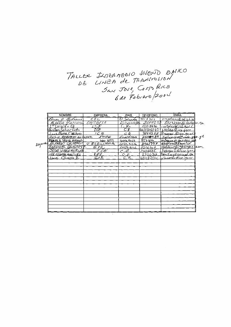
Taller Intermedio Diseño Básico de la Línea San José, Costa Rica, 6 de Febrero 2004.
1. ACTO INAGURAL El Ing. Francisco Núñez, Gerente General de EPR, dio la bienvenida a los asistentes y mencionó que el objetivo de este taller era analizar y discutir aspectos técnicos del diseño de la línea para continuar con el estudio, asimismo recalcó que anteriormente la región aprobó un diseño preliminar el cual era la base para que el consultor hiciera una revisión mejorando el diseño con la información actual. 2. DISCUSIÓN DE LA AGENDA Previamente se envió por correo electrónico la agenda a tratar con el consultor, se sometió a consideración, la cual fue aprobada y se adjunta como Anexo No. 1. 3. PARTICIPANTES Durante la reunión se contó con la participación de los representantes de Guatemala, El Salvador, Nicaragua, Costa Rica, Unidad Ejecutora, BID y EPR. El detalle de los asistentes se adjunta como Anexo No. 2. 4. OBJETIVOS DE LA REUNIÓN El objetivo de este taller era informar del avance del estudio y analizar los aspectos técnicos planteados por el consultor en el primer taller. 5. DESARROLLO DE LA REUNION 5.1. CONDUCTOR.
El Consultor dio una amplia explicación del por qué se cambió el conductor propuesto en los estudios de DPC (Cóndor 795 ACSR) mencionando que los aspectos más importantes considerados son los fenómenos corona y sus efectos eléctricos y ambientales en las líneas de 230 kV operando a alturas que superan los 1000 metros, adicionalmente mencionó otros beneficios de confiabilidad, seguridad y reducción de pérdidas.
5.2 VIENTOS
Se discutió la propuesta de emplear una velocidad de 100 kph y una presión de 48 kg/m2, dado que se ajusta en la mayor medida a la experiencia de los países.
5.3 ESTRUCTURAS
El Consultor expuso que luego de conocer el caso de las salidas de línea en las subestaciones en Guatemala y la experiencia que este país ha tenido con el uso de postes de concreto, se analizará como una opción su uso en casos con restricciones en el derecho de vía.
El Consultor expuso la necesidad de considerar el impacto en la confiabilidad que significa emplear estructuras de 4 circuitos en paralelo con una línea existente. Indica que sería mejor tratar de obtener una franja de servidumbre mayor y separar los circuitos. El Consultor solicitó a los países que usarán torres de 2 circuitos (El Salvador y Costa Rica) revisar las prestaciones (vanos) propuestas para dichas estructuras. El Consultor sometió a consideración de los participantes el cuadro “Familia de estructuras”, en la cual considera 5 tipos de torres de un circuito, 5 tipos de dos circuitos, 2 de base estrecha de 1 circuito, 2 de base estrecha de 2 circuitos y varios tipos de estructuras especiales estéticas y compactas y 3 tipos de torres para 4 circuitos. Se expuso la configuración de la “cabeza” de la torre. Se dijo que con respecto a la propuesta enviada antes de la reunión se incrementará la separación vertical entre fases de 5.80 a 5.90 m, y la longitud del brazo inferior se disminuyó de 4.30 a 4.0 metros pues no es necesario que sea sensiblemente mayor al brazo superior. El Consultor explica que los ángulos de desvío (swing) se calcularon para una relación vano peso/vano de viento = 0.6, con lo cual es muy probable que no se requieran contrapesos.
Se explicó la configuración básica de la torre de suspensión, con un cuerpo base de 15 m, extensiones de cuerpo de 6, 9 y 12 m, y patas de -3 a + 3 en pasos de 1m. Posteriormente se enviarán las geometrías de los otros tipos de estructura.
• Hipótesis de carga (este tema no se envió antes de la reunión, el material será remitido
a los países):
o Contención de falla: Se define para evitar la propagación de una falla por rotura de un conductor o un hilo de guarda a la vez (sin viento). El coeficiente es de 1.2. (Hará el efecto necesario para evitar la cascada).
o Desbalance longitudinal: Se presenta cuando por condiciones de viento u otras
condiciones se dan cargas longitudinales diferentes en las fases. Se emplea un coeficiente de carga extraordinaria de 1.2.

o Construcción: corresponde a las operaciones de tendido. Emplea coeficiente de seguridad de 2 (o al menos superior a 1.5) ya que en la maniobra se involucra personal.
o Mantenimiento: corresponde a operaciones como el levantado del conductor.
Emplea el coeficiente de seguridad mayor a 1.5. (involucra personal).
o Normal: En este caso se propone considerar adicional a las cargas normales un desbalance longitudinal originado en vanos adyacentes con longitudes o alturas muy diferentes. El Consultor indica que según sus cálculos estas diferencias pueden ser pequeñas y se pueden calcular.
Con respecto a las torres intermedias en tangentes largas se analizará el caso de Nicaragua donde hay una tangente de más de 20 km.
5.4 DESEMPEÑO DE LÍNEAS CONTRA DESCARGAS ATMOSFÉRICAS.
En vista de los altos niveles ceráunicos de la zona se está proponiendo el uso de un ángulo de blindaje de -10 grados. Esto unido a una puesta a tierra de 10 ohmios y a 16 aisladores permitiría tener un buen desempeño ante descargas atmosféricas (menor o igual a 1 salida-año/100 km). Los resultados teóricos son los mismos para 5 y 10 ohmios por lo que es suficiente con este último valor.
6 OTROS TEMAS ABIERTOS.
Ante la pregunta de Nicaragua, el Consultor indica que es necesario que en las especificaciones técnicas se solicite verificar el efecto de los sismos con una aceleración
7. RECOMENDACIONES
• El Consultor recomienda analizar la posibilidad de adquirir franjas de terreno amplias y tratar de evitar el empleo de estructuras de 4 circuitos paralelas a líneas existentes.
• Se definió el uso de estructuras compactas (postes de concreto o de acero) en tramos con restricciones de servidumbre.
• Se solicitó a los representantes de los países que investigaran sobre los valores de aceleración sísmica usados en sus respectivos países y comunicarlo al Consultor.
8. CONCLUSIONES
1. Aceptar el conductor planteado por el Consultor (ACAR 1024.5 18/19), en consideración a evitar los efectos ambientales sobre la línea como el tipo corona, y
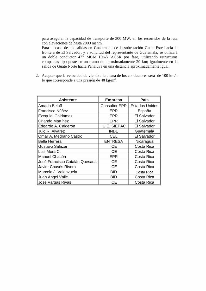
para asegurar la capacidad de transporte de 300 MW, en los recorridos de la ruta con elevaciones de hasta 2000 msnm. Para el caso de las salidas en Guatemala: de la subestación Guate-Este hacia la frontera de El Salvador, y a solicitud del representante de Guatemala, se utilizará un doble conductor 477 MCM Hawk ACSR por fase, utilizando estructuras compactas tipo poste en un tramo de aproximadamente 20 km; igualmente en la salida de Guate Norte hacia Panaluya en una distancia aproximadamente igual.
2. Aceptar que la velocidad de viento a la altura de los conductores será de 100 km/h lo que corresponde a una presión de 48 kg/m2.
Asistente Empresa País Amado Beloff Consultor EPR Estados Unidos Francisco Núñez EPR España Ezequiel Galdámez EPR El Salvador Orlando Martínez EPR El Salvador Edgardo A. Calderón U.E. SIEPAC El Salvador Juio R. Alvarez INDE Guatemala Omar A. Medrano Castro CEL El Salvador Bella Herrera ENTRESA Nicaragua Gustavo Salazar ICE Costa Rica Luis Mora C. ICE Costa Rica Manuel Chacón EPR Costa Rica José Francisco Catalán Quesada ICE Costa Rica Javier Chavés Rivera ICE Costa Rica Marcelo J. Valenzuela BID Costa Rica Juan Angel Valle BID Costa Rica José Vargas Rivas ICE Costa Rica
ANEXO 27A
Hojas de Cálculo de las Estructuras Normales
(1 Circuito TS1, TS2, TSA, TMS, TSD) (2 Circuitos TD1, TD2, TDA, TMD, TDD)
(1 Circuito Base Estrecha TES1, TEMS) (2 Circuitos Base Estrecha TED1, TEMD)
(1 Circuito Estructuras Estéticas PS1, PMS) (2 Circuitos Estructuras Estéticas PD1, PMD)
TORRES DE CIRCUITO SIMPLE NORMALES
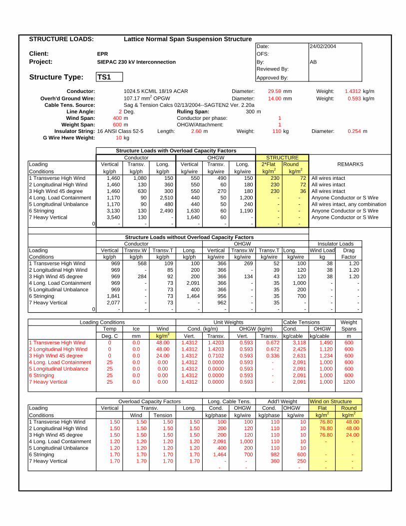
STRUCTURE LOADS: Lattice Normal Span Suspension StructureDate:
Client: EPR OFS:Project: SIEPAC 230 kV Interconnection By: AB
Reviewed By:
Structure Type: TS1 Approved By:
Conductor: 1024.5 KCMIL 18/19 ACAR Diameter: 29.59 mm Weight: 1.4312 kg/mOverh'd Ground Wire: 107.17 mm2 OPGW Diameter: 14.00 mm Weight: 0.593 kg/m
Cable Tens. Source: Sag & Tension Calcs 02/13/2004--SAGTEN2 Ver. 2.20aLine Angle: 2 Deg. Ruling Span: 300 mWind Span: 400 m Conductor per phase: 1
Weight Span: 600 m OHGW/Attachment: 1Insulator String: 16 ANSI Class 52-5 Length: 2.60 m Weight: 110 kg Diameter: 0.254 m
G Wire Hwre Weight: 10 kg
Structure Loads with Overload Capacity FactorsConductor OHGW
Loading Vertical Transv. Long. Vertical Transv. Long. 2*Flat RoundConditions kg/ph kg/ph kg/ph kg/wire kg/wire kg/wire kg/m2 kg/m2
1 Transverse High Wind 1,460 1,080 150 550 490 150 230 72 All wires intact2 Longitudinal High Wind 1,460 130 360 550 60 180 230 72 All wires intact3 High Wind 45 degree 1,460 630 300 550 270 180 230 36 All wires intact4 Long. Load Containment 1,170 90 2,510 440 50 1,200 - - Anyone Conductor or S Wire5 Longitudinal Unbalance 1,170 90 480 440 50 240 - - All wires intact, any combination6 Stringing 3,130 130 2,490 1,630 60 1,190 - - Anyone Conductor or S Wire7 Heavy Vertical 3,540 130 - 1,640 60 - - - Anyone Conductor or S Wire
0 - - - - - - - -
Structure Loads without Overload Capacity FactorsConductor OHGW
Loading Vertical Transv.W Transv.T Long. Vertical Transv.W Transv.T Long. Wind Load DragConditions kg/ph kg/ph kg/ph kg/ph kg/wire kg/wire kg/wire kg/wire kg Factor1 Transverse High Wind 969 568 109 100 366 269 52 100 38 1.202 Longitudinal High Wind 969 - 85 200 366 - 39 120 38 1.203 High Wind 45 degree 969 284 92 200 366 134 43 120 38 1.204 Long. Load Containment 969 - 73 2,091 366 - 35 1,000 - - 5 Longitudinal Unbalance 969 - 73 400 366 - 35 200 - - 6 Stringing 1,841 - 73 1,464 956 - 35 700 - - 7 Heavy Vertical 2,077 - 73 - 962 - 35 - - -
0 - - - - - - - - - -
Loading Conditions Unit Weights Cable Tensions WeightTemp Ice Wind Cond. (kg/m) OHGW (kg/m) Cond. OHGW Spans
Deg. C mm kg/m2 Vert. Transv. Vert. Transv. kg/cable kg/cable m1 Transverse High Wind 0 0.0 48.00 1.4312 1.4203 0.593 0.672 3,118 1,490 6002 Longitudinal High Wind 0 0.0 48.00 1.4312 1.4203 0.593 0.672 2,425 1,120 6003 High Wind 45 degree 0 0.0 24.00 1.4312 0.7102 0.593 0.336 2,631 1,234 6004 Long. Load Containment 25 0.0 0.00 1.4312 0.0000 0.593 - 2,091 1,000 6005 Longitudinal Unbalance 25 0.0 0.00 1.4312 0.0000 0.593 - 2,091 1,000 6006 Stringing 25 0.0 0.00 1.4312 0.0000 0.593 - 2,091 1,000 6007 Heavy Vertical 25 0.0 0.00 1.4312 0.0000 0.593 - 2,091 1,000 1200
Overload Capacity Factors Long. Cable Tens. Add'l Weight Wind on StructureLoading Vertical Transv. Long. Cond. OHGW Cond. OHGW Flat RoundConditions Wind Tension kg/phase kg/wire kg/phase kg/wire kg/m2 kg/m2
1 Transverse High Wind 1.50 1.50 1.50 1.50 100 100 110 10 76.80 48.00 2 Longitudinal High Wind 1.50 1.50 1.50 1.50 200 120 110 10 76.80 48.00 3 High Wind 45 degree 1.50 1.50 1.50 1.50 200 120 110 10 76.80 24.00 4 Long. Load Containment 1.20 1.20 1.20 1.20 2,091 1,000 110 10 - - 5 Longitudinal Unbalance 1.20 1.20 1.20 1.20 400 200 110 10 6 Stringing 1.70 1.70 1.70 1.70 1,464 700 982 600 - - 7 Heavy Vertical 1.70 1.70 1.70 1.70 - - 360 250 - -
- - - - -
24/02/2004
REMARKS
Insulator Loads
STRUCTURE

STRUCTURE LOADS: Lattice Long Span Suspension StructureDate:
Client: EPR OFS:Project: SIEPAC 230 kV Interconnection By: AB
Reviewed By:
Structure Type: TS2 Approved By:
Conductor: 1024.5 KCMIL 18/19 ACAR Diameter: 29.59 mm Weight: 1.4312 kg/mOverh'd Ground Wire: 107.17 mm2 OPGW Diameter: 14.00 mm Weight: 0.593 kg/m
Cable Tens. Source: Sag & Tension Calcs 02/13/2004--SAGTEN2 Ver. 2.20aLine Angle: 2 Deg. Ruling Span: 300 mWind Span: 700 m Conductor per phase: 1
Weight Span: 1050 m OHGW/Attachment: 1Insulator String: 16 ANSI Class 52-5 Length: 2.60 m Weight: 110 kg Diameter: 0.254 m
G Wire Hwre Weight: 10 kg
Structure Loads with Overload Capacity FactorsConductor OHGW
Loading Vertical Transv. Long. Vertical Transv. Long. 2*Flat RoundConditions kg/ph kg/ph kg/ph kg/wire kg/wire kg/wire kg/m2 kg/m2
1 Transverse High Wind 2,420 1,720 150 950 790 150 230 72 All wires intact2 Longitudinal High Wind 2,420 130 360 950 60 180 230 72 All wires intact3 High Wind 45 degree 2,420 950 300 950 420 180 230 36 All wires intact4 Long. Load Containment 1,940 90 2,510 760 50 1,200 - - Anyone Conductor or S Wire5 Longitudinal Unbalance 1,940 90 480 760 50 240 - - All wires intact, any combination6 Stringing 4,230 130 2,490 2,080 60 1,190 - - Anyone Conductor or S Wire7 Heavy Vertical 5,730 130 - 2,550 60 - - - Anyone Conductor or S Wire
0 - - - - - - - -
Structure Loads without Overload Capacity FactorsConductor OHGW
Loading Vertical Transv.W Transv.T Long. Vertical Transv.W Transv.T Long. Wind Load DragConditions kg/ph kg/ph kg/ph kg/ph kg/wire kg/wire kg/wire kg/wire kg Factor1 Transverse High Wind 1,613 994 109 100 633 470 52 100 38 1.202 Longitudinal High Wind 1,613 - 85 200 633 - 39 120 38 1.203 High Wind 45 degree 1,613 497 92 200 633 235 43 120 38 1.204 Long. Load Containment 1,613 - 73 2,091 633 - 35 1,000 - - 5 Longitudinal Unbalance 1,613 - 73 400 633 - 35 200 - - 6 Stringing 2,485 - 73 1,464 1,223 - 35 700 - - 7 Heavy Vertical 3,366 - 73 - 1,495 - 35 - - -
0 - - - - - - - - - -
Loading Conditions Unit Weights Cable Tensions WeightTemp Ice Wind Cond. (kg/m) OHGW (kg/m) Cond. OHGW Spans
Deg. C mm kg/m2 Vert. Transv. Vert. Transv. kg/cable kg/cable m1 Transverse High Wind 0 0.0 48.00 1.4312 1.4203 0.593 0.672 3,118 1,490 10502 Longitudinal High Wind 0 0.0 48.00 1.4312 1.4203 0.593 0.672 2,425 1,120 10503 High Wind 45 degree 0 0.0 24.00 1.4312 0.7102 0.593 0.336 2,631 1,234 10504 Long. Load Containment 25 0.0 0.00 1.4312 0.0000 0.593 - 2,091 1,000 10505 Longitudinal Unbalance 25 0.0 0.00 1.4312 0.0000 0.593 - 2,091 1,000 10506 Stringing 25 0.0 0.00 1.4312 0.0000 0.593 - 2,091 1,000 10507 Heavy Vertical 25 0.0 0.00 1.4312 0.0000 0.593 - 2,091 1,000 2100
Overload Capacity Factors Long. Cable Tens. Add'l Weight Wind on StructureLoading Vertical Transv. Long. Cond. OHGW Cond. OHGW Flat RoundConditions Wind Tension kg/phase kg/wire kg/phase kg/wire kg/m2 kg/m2
1 Transverse High Wind 1.50 1.50 1.50 1.50 100 100 110 10 76.80 48.00 2 Longitudinal High Wind 1.50 1.50 1.50 1.50 200 120 110 10 76.80 48.00 3 High Wind 45 degree 1.50 1.50 1.50 1.50 200 120 110 10 76.80 24.00 4 Long. Load Containment 1.20 1.20 1.20 1.20 2,091 1,000 110 10 - - 5 Longitudinal Unbalance 1.20 1.20 1.20 1.20 400 200 110 10 6 Stringing 1.70 1.70 1.70 1.70 1,464 700 982 600 - - 7 Heavy Vertical 1.70 1.70 1.70 1.70 - 1,000 360 250 - -
- - - - -
24/02/2004
REMARKS
Insulator Loads
STRUCTURE

STRUCTURE LOADS: Lattice Suspension and Small Angle StructureDate:
Client: EPR OFS:Project: SIEPAC 230 kV Interconnection By: AB
Reviewed By:
Structure Type: TSA Approved By:
Conductor: 1024.5 KCMIL 18/19 ACAR Diameter: 29.59 mm Weight: 1.4312 kg/mOverh'd Ground Wire: 107.17 mm2 OPGW Diameter: 14.00 mm Weight: 0.593 kg/m
Cable Tens. Source: Sag & Tension Calcs 02/13/2004--SAGTEN2 Ver. 2.20aLine Angle: 10 Deg. Ruling Span: 300 mWind Span: 400 m Conductor per phase: 1
Weight Span: 1050 m OHGW/Attachment: 1Insulator String: 16 ANSI Class 52-5 Length: 2.60 m Weight: 110 kg Diameter: 0.254 m
G Wire Hwre Weight: 10 kg
Structure Loads with Overload Capacity FactorsConductor OHGW
Loading Vertical Transv. Long. Vertical Transv. Long. 2*Flat RoundConditions kg/ph kg/ph kg/ph kg/wire kg/wire kg/wire kg/m2 kg/m2
1 Transverse High Wind 2,420 1,730 150 950 800 150 230 72 All wires intact2 Longitudinal High Wind 2,420 640 360 950 300 180 230 72 All wires intact3 High Wind 45 degree 2,420 1,180 300 950 530 180 230 36 All wires intact4 Long. Load Containment 1,940 440 2,510 760 210 1,200 - - Anyone Conductor or S Wire5 Longitudinal Unbalance 1,940 440 480 760 210 240 - - All wires intact, any combination6 Stringing 4,230 620 2,490 2,080 300 1,190 - - Anyone Conductor or S Wire7 Heavy Vertical 5,730 620 - 2,550 300 - - - Anyone Conductor or S Wire
0 - - - - - - - -
Structure Loads without Overload Capacity FactorsConductor OHGW
Loading Vertical Transv.W Transv.T Long. Vertical Transv.W Transv.T Long. Wind Load DragConditions kg/ph kg/ph kg/ph kg/ph kg/wire kg/wire kg/wire kg/wire kg Factor1 Transverse High Wind 1,613 568 544 100 633 269 260 100 38 1.202 Longitudinal High Wind 1,613 - 423 200 633 - 195 120 38 1.203 High Wind 45 degree 1,613 284 459 200 633 134 215 120 38 1.204 Long. Load Containment 1,613 - 364 2,091 633 - 174 1,000 - - 5 Longitudinal Unbalance 1,613 - 364 400 633 - 174 200 - - 6 Stringing 2,485 - 364 1,464 1,223 - 174 700 - - 7 Heavy Vertical 3,366 - 364 - 1,495 - 174 - - -
0 - - - - - - - - - -
Loading Conditions Unit Weights Cable Tensions WeightTemp Ice Wind Cond. (kg/m) OHGW (kg/m) Cond. OHGW SpansDeg. C mm kg/m2 Vert. Transv. Vert. Transv. kg/cable kg/cable m
1 Transverse High Wind 0 0.0 48.00 1.4312 1.4203 0.593 0.672 3,118 1,490 10502 Longitudinal High Wind 0 0.0 48.00 1.4312 1.4203 0.593 0.672 2,425 1,120 10503 High Wind 45 degree 0 0.0 24.00 1.4312 0.7102 0.593 0.336 2,631 1,234 10504 Long. Load Containment 25 0.0 0.00 1.4312 0.0000 0.593 - 2,091 1,000 10505 Longitudinal Unbalance 25 0.0 0.00 1.4312 0.0000 0.593 - 2,091 1,000 10506 Stringing 25 0.0 0.00 1.4312 0.0000 0.593 - 2,091 1,000 10507 Heavy Vertical 25 0.0 0.00 1.4312 0.0000 0.593 - 2,091 1,000 2100
Overload Capacity Factors Long. Cable Tens. Add'l Weight Wind on StructureLoading Vertical Transv. Long. Cond. OHGW Cond. OHGW Flat RoundConditions Wind Tension kg/phase kg/wire kg/phase kg/wire kg/m2 kg/m2
1 Transverse High Wind 1.50 1.50 1.50 1.50 100 100 110 10 76.80 48.00 2 Longitudinal High Wind 1.50 1.50 1.50 1.50 200 120 110 10 76.80 48.00 3 High Wind 45 degree 1.50 1.50 1.50 1.50 200 120 110 10 76.80 24.00 4 Long. Load Containment 1.20 1.20 1.20 1.20 2,091 1,000 110 10 - - 5 Longitudinal Unbalance 1.20 1.20 1.20 1.20 400 200 110 10 6 Stringing 1.70 1.70 1.70 1.70 1,464 700 982 600 - - 7 Heavy Vertical 1.70 1.70 1.70 1.70 - 1,000 360 250 - -
- - - - -
24/02/2004
REMARKS
Insulator Loads
STRUCTURE

STRUCTURE LOADS: Lattice Medium Angle Deadend StructureDate:
Client: EPR OFS:Project: SIEPAC 230 kV Interconnection By: AB
Reviewed By:
Structure Type: TMS Approved By:
Conductor: 1024.5 KCMIL 18/19 ACAR Diameter: 29.59 mm Weight: 1.4312 kg/mOverh'd Ground Wire: 107.17 mm2 OPGW Diameter: 14.00 mm Weight: 0.593 kg/m
Cable Tens. Source: Sag & Tension Calcs 02/13/2004--SAGTEN2 Ver. 2.20aLine Angle: 30 Deg. Ruling Span: 300 mWind Span: 400 m Conductor per phase: 1
Weight Span: 1500 m OHGW/Attachment: 1Insulator String: 16 ANSI Class 52-5 Length: 2.60 m Weight: 110 kg Diameter: 0.254 m
G Wire Hwre Weight: 20 kg
Structure Loads with Overload Capacity FactorsConductor OHGW
Loading Vertical Transv. Long. Vertical Transv. Long. 2*Flat RoundConditions kg/ph kg/ph kg/ph kg/wire kg/wire kg/wire kg/m2 kg/m2
1 Transverse High Wind 3,720 3,340 750 1,370 1,570 380 230 72 All wires intact2 Longitudinal High Wind 3,720 1,890 360 1,370 870 180 230 72 All wires intact3 High Wind 45 degree 3,720 2,530 300 1,370 1,160 180 230 36 All wires intact4 Temporary deadend EDS 2,980 650 2,510 1,100 320 1,200 - - One or all wires, one side only5 Stringing 5,320 1,850 2,490 2,540 880 1,190 - - Anyone conductor or S. Wire6 Heavy Vertical 6,100 1,850 - 2,550 880 - - - Anyone conductor or S. Wire
0 - - - - - - - -
Structure Loads without Overload Capacity FactorsConductor OHGW
Loading Vertical Transv.W Transv.T Long. Vertical Transv.W Transv.T Long. Wind Load DragConditions kg/ph kg/ph kg/ph kg/ph kg/wire kg/wire kg/wire kg/wire kg Factor1 Transverse High Wind 2,477 568 1,614 500 910 269 771 250 38 1.202 Longitudinal High Wind 2,477 - 1,255 200 910 - 580 120 38 1.203 High Wind 45 degree 2,477 284 1,362 200 910 134 639 120 38 1.204 Temporary deadend EDS 2,477 - 541 2,091 910 - 259 1,000 - - 5 Stringing 3,129 - 1,082 1,464 1,490 - 518 700 - - 6 Heavy Vertical 3,586 - 1,082 2,091 1,495 - 518 1,000 - -
0 - - - - - - 518 - - 518
Loading Conditions Unit Weights Cable Tensions WeightTemp Ice Wind Cond. (kg/m) OHGW (kg/m) Cond. OHGW Spans
Deg. C mm kg/m2 Vert. Transv. Vert. Transv. kg/cable kg/cable m1 Transverse High Wind 0 0.0 48.00 1.4312 1.4203 0.593 0.672 3,118 1,490 15002 Longitudinal High Wind 0 0.0 48.00 1.4312 1.4203 0.593 0.672 2,425 1,120 15003 High Wind 45 degree 0 0.0 24.00 1.4312 0.7102 0.593 0.336 2,631 1,234 15004 Temporary deadend EDS 25 0.0 0.00 1.4312 0.0000 0.593 - 2,091 1,000 15005 Stringing 25 0.0 0.00 1.4312 0.0000 0.593 - 2,091 1,000 15006 Heavy Vertical 25 0.0 0.00 1.4312 0.0000 0.593 - 2,091 1,000 2100
1,000
Overload Capacity Factors Long. Cable Tens. Add'l Weight Wind on StructureLoading Vertical Transv. Long. Cond. OHGW Cond. OHGW Flat RoundConditions Wind Tension kg/phase kg/wire kg/phase kg/wire kg/m2 kg/m2
1 Transverse High Wind 1.50 1.50 1.50 1.50 500 250 110 20 76.80 48.00 2 Longitudinal High Wind 1.50 1.50 1.50 1.50 200 120 110 20 76.80 48.00 3 High Wind 45 degree 1.50 1.50 1.50 1.50 200 120 110 20 76.80 24.00 4 Temporary deadend EDS 1.20 1.20 1.20 1.20 2,091 1,000 110 20 - - 5 Stringing 1.70 1.70 1.70 1.70 1,464 700 982 600 - - 6 Heavy Vertical 1.70 1.70 1.70 1.70 2,091 1,000 580 250 - -
- 1,000 - - -
24/02/2004
REMARKS
Insulator Loads
STRUCTURE

STRUCTURE LOADS: Lattice Medium Angle Deadend StructureDate:
Client: EPR OFS:Project: SIEPAC 230 kV Interconnection By: AB
Reviewed By:
Structure Type: TMS Approved By:
Conductor: 1024.5 KCMIL 18/19 ACAR Diameter: 29.59 mm Weight: 1.4312 kg/mOverh'd Ground Wire: 107.17 mm2 OPGW Diameter: 14.00 mm Weight: 0.593 kg/m
Cable Tens. Source: Sag & Tension Calcs 02/13/2004--SAGTEN2 Ver. 2.20aLine Angle: 30 Deg. Ruling Span: 300 mWind Span: 400 m Conductor per phase: 1
Weight Span: -900 m OHGW/Attachment: 1Insulator String: 16 ANSI Class 52-5 Length: 2.60 m Weight: 110 kg Diameter: 0.254 m
G Wire Hwre Weight: 20 kg
Structure Loads with Overload Capacity FactorsConductor OHGW
Loading Vertical Transv. Long. Vertical Transv. Long. 2*Flat RoundConditions kg/ph kg/ph kg/ph kg/wire kg/wire kg/wire kg/m2 kg/m2
1 Transverse High Wind (1,440) 3,340 750 (780) 1,570 380 230 72 All wires intact2 Longitudinal High Wind (1,440) 1,890 360 (780) 870 180 230 72 All wires intact3 High Wind 45 degree (1,440) 2,530 300 (780) 1,160 180 230 36 All wires intact4 Temporary deadend EDS (1,150) 650 2,510 (620) 320 1,200 - - One or all wires, one side only5 Stringing 5,320 1,850 2,490 2,540 880 1,190 - - Anyone conductor or S. Wire6 Heavy Vertical 6,100 1,850 - 2,550 880 - - - Anyone conductor or S. Wire
0 - - - - - - - -
Structure Loads without Overload Capacity FactorsConductor OHGW
Loading Vertical Transv.W Transv.T Long. Vertical Transv.W Transv.T Long. Wind Load DragConditions kg/ph kg/ph kg/ph kg/ph kg/wire kg/wire kg/wire kg/wire kg Factor1 Transverse High Wind (958) 568 1,614 500 (514) 269 771 250 38 1.202 Longitudinal High Wind (958) - 1,255 200 (514) - 580 120 38 1.203 High Wind 45 degree (958) 284 1,362 200 (514) 134 639 120 38 1.204 Temporary deadend EDS (958) - 541 2,091 (514) - 259 1,000 - - 5 Stringing 3,129 - 1,082 1,464 1,490 - 518 700 - - 6 Heavy Vertical 3,586 - 1,082 2,091 1,495 - 518 1,000 - -
0 - - - - - - 518 - - 518
Loading Conditions Unit Weights Cable Tensions WeightTemp Ice Wind Cond. (kg/m) OHGW (kg/m) Cond. OHGW SpansDeg. C mm kg/m2 Vert. Transv. Vert. Transv. kg/cable kg/cable m
1 Transverse High Wind 0 0.0 48.00 1.4312 1.4203 0.593 0.672 3,118 1,490 -9002 Longitudinal High Wind 0 0.0 48.00 1.4312 1.4203 0.593 0.672 2,425 1,120 -9003 High Wind 45 degree 0 0.0 24.00 1.4312 0.7102 0.593 0.336 2,631 1,234 -9004 Temporary deadend EDS 25 0.0 0.00 1.4312 0.0000 0.593 - 2,091 1,000 -9005 Stringing 25 0.0 0.00 1.4312 0.0000 0.593 - 2,091 1,000 15006 Heavy Vertical 25 0.0 0.00 1.4312 0.0000 0.593 - 2,091 1,000 2100
1,000
Overload Capacity Factors Long. Cable Tens. Add'l Weight Wind on StructureLoading Vertical Transv. Long. Cond. OHGW Cond. OHGW Flat RoundConditions Wind Tension kg/phase kg/wire kg/phase kg/wire kg/m2 kg/m2
1 Transverse High Wind 1.50 1.50 1.50 1.50 500 250 110 20 76.80 48.00 2 Longitudinal High Wind 1.50 1.50 1.50 1.50 200 120 110 20 76.80 48.00 3 High Wind 45 degree 1.50 1.50 1.50 1.50 200 120 110 20 76.80 24.00 4 Temporary deadend EDS 1.20 1.20 1.20 1.20 2,091 1,000 110 20 - - 5 Stringing 1.70 1.70 1.70 1.70 1,464 700 982 600 - - 6 Heavy Vertical 1.70 1.70 1.70 1.70 2,091 1,000 580 250 - -
- 1,000 - - -
06/03/2004
REMARKS
Insulator Loads
STRUCTURE

STRUCTURE LOADS: Lattice Terminal and Large Angle Deadend StructureDate:
Client: EPR OFS:Project: SIEPAC 230 kV Interconnection By: AB
Reviewed By:
Structure Type: TDS Approved By:
Conductor: 1024.5 KCMIL 18/19 ACAR Diameter: 29.59 mm Weight: 1.4312 kg/mOverh'd Ground Wire: 107.17 mm2 OPGW Diameter: 14.00 mm Weight: 0.593 kg/m
Cable Tens. Source: Sag & Tension Calcs 02/13/2004--SAGTEN2 Ver. 2.20aLine Angle: 65 Deg. Ruling Span: 300 mWind Span: 400 m Conductor per phase: 1
Weight Span: 1500 m OHGW/Attachment: 1Insulator String: 16 ANSI Class 52-5 Length: 2.60 m Weight: 110 kg Diameter: 0.254 m
G Wire Hwre Weight: 20 kg
Structure Loads with Overload Capacity FactorsConductor OHGW
Loading Vertical Transv. Long. Vertical Transv. Long. 2*Flat RoundConditions kg/ph kg/ph kg/ph kg/wire kg/wire kg/wire kg/m2 kg/m2
1 Angle Trans High Wind 3,720 5,940 640 1,370 2,810 320 230 72 All wires intact2 Angle Long High Wind 3,720 3,910 570 1,370 1,810 260 230 72 All wires intact3 Angle 45 deg High Wind 3,720 4,730 510 1,370 2,200 260 230 36 All wires intact4 Term Trans High Wind 2,920 3,210 3,950 1,040 1,610 1,890 230 72 All wires intact, one side only5 Term Long High Wind 2,920 1,960 3,130 1,040 910 1,420 230 72 All wires intact, one side only6 Term 45 deg High Wind 2,920 2,500 3,330 1,040 1,200 1,570 230 36 All wires intact, one side only7 Stringing 5,320 2,680 2,100 2,540 1,830 1,010 8 Heavy Vertical EDS 6,100 3,820 - 2,550 1,830 - - - One conductor or one S Wire
Structure Loads without Overload Capacity Factors
Loading Vertical Transv.W Transv.T Long. Vertical Transv.W Transv.T Long. Wind Load DragConditions kg/ph kg/ph kg/ph kg/ph kg/wire kg/wire kg/wire kg/wire kg Factor1 Angle Trans High Wind 2,477 568 3,351 422 910 269 1,601 211 38 1.202 Angle Long High Wind 2,477 - 2,606 337 910 - 1,204 169 38 1.203 Angle 45 deg High Wind 2,477 284 2,827 337 910 134 1,326 169 38 1.20 4 Term Trans High Wind 1,940 426 1,675 2,630 687 269 801 1,257 38 1.20 5 Term Long High Wind 1,940 - 1,303 2,045 687 - 602 945 38 1.20 6 Term 45 deg High Wind 1,940 213 1,414 2,219 687 134 663 1,041 38 1.20 7 Stringing 3,129 - 1,573 1,234 1,490 - 1,075 590 - -8 Heavy Vertical EDS 3,586 - 2,247 - 1,495 - 1,075 - - -
- Loading Conditions Unit Weights Cable Tensions Weight
Temp Ice Wind Cond. (kg/m) OHGW (kg/m) Cond. OHGW SpansDeg. C mm kg/m2 Vert. Transv. Vert. Transv. kg/cable kg/cable m
1 Angle Trans High Wind 0 0.0 48.00 1.4312 1.4203 0.593 0.672 3,118 1,490 15002 Angle Long High Wind 0 0.0 48.00 1.4312 1.4203 0.593 0.672 2,425 1,120 15003 Angle 45 deg High Wind 0 0.0 24.00 1.4312 0.7102 0.593 0.336 2,631 1,234 15004 Term Trans High Wind 0 0.0 48.00 1.4312 1.4203 0.593 0.672 3,118 1,490 15005 Term Long High Wind 0 0.0 48.00 1.4312 1.4203 0.593 0.672 2,425 1,120 15006 Term 45 deg High Wind 0 0.0 24.00 1.4312 0.7102 0.593 0.336 2,631 1,234 15007 Stringing 25 0.0 0.00 1.4312 0.0000 0.593 - 2,091 1,000 15008 Heavy Vertical EDS 25 0.0 0.00 1.4312 0.0000 0.593 - 2,091 1,000 2100
Overload Capacity Factors Long. Cable Tens. Add'l Weight Wind on StructureLoading Vertical Transv. Long. Cond. OHGW Cond. OHGW Flat RoundConditions Wind Tension kg/phase kg/wire kg/phase kg/wire kg/m2 kg/m2 345.61 Angle Trans High Wind 1.50 1.50 1.50 1.50 500 250 110 20 76.80 48.00 2 Angle Long High Wind 1.50 1.50 1.50 1.50 400 200 110 20 76.80 48.00 3 Angle 45 deg High Wind 1.50 1.50 1.50 1.50 400 200 110 20 38.40 24.00 4 Term Trans High Wind 1.50 1.50 1.50 1.50 3,118 1,490 110 20 76.80 48.00 5 Term Long High Wind 1.50 1.50 1.50 1.50 2,425 1,120 110 20 76.80 48.00 6 Term 45 deg High Wind 1.50 1.50 1.50 1.50 2,631 1,234 110 20 38.40 24.00 7 Stringing 1.70 1.70 1.70 1.70 1,464 700 982 600 8 Heavy Vertical EDS 1.70 1.00 1.70 1.70 - - 580 250 - -
Conductor OHGW
24/02/2004
REMARKS
Insulator Loads
STRUCTURE
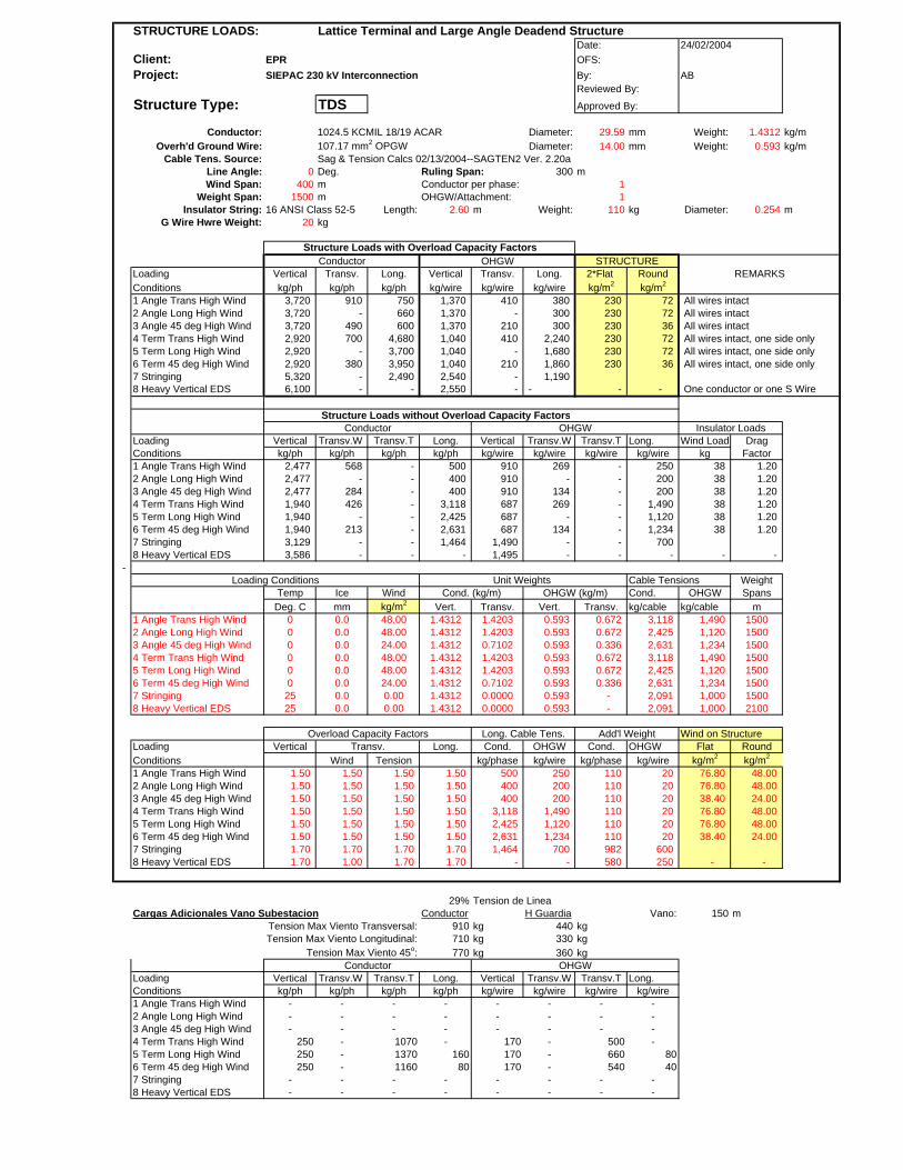
STRUCTURE LOADS: Lattice Terminal and Large Angle Deadend StructureDate:
Client: EPR OFS:Project: SIEPAC 230 kV Interconnection By: AB
Reviewed By:
Structure Type: TDS Approved By:
Conductor: 1024.5 KCMIL 18/19 ACAR Diameter: 29.59 mm Weight: 1.4312 kg/mOverh'd Ground Wire: 107.17 mm2 OPGW Diameter: 14.00 mm Weight: 0.593 kg/m
Cable Tens. Source: Sag & Tension Calcs 02/13/2004--SAGTEN2 Ver. 2.20aLine Angle: 0 Deg. Ruling Span: 300 mWind Span: 400 m Conductor per phase: 1
Weight Span: 1500 m OHGW/Attachment: 1Insulator String: 16 ANSI Class 52-5 Length: 2.60 m Weight: 110 kg Diameter: 0.254 m
G Wire Hwre Weight: 20 kg
Structure Loads with Overload Capacity FactorsConductor OHGW
Loading Vertical Transv. Long. Vertical Transv. Long. 2*Flat RoundConditions kg/ph kg/ph kg/ph kg/wire kg/wire kg/wire kg/m2 kg/m2
1 Angle Trans High Wind 3,720 910 750 1,370 410 380 230 72 All wires intact2 Angle Long High Wind 3,720 - 660 1,370 - 300 230 72 All wires intact3 Angle 45 deg High Wind 3,720 490 600 1,370 210 300 230 36 All wires intact4 Term Trans High Wind 2,920 700 4,680 1,040 410 2,240 230 72 All wires intact, one side only5 Term Long High Wind 2,920 - 3,700 1,040 - 1,680 230 72 All wires intact, one side only6 Term 45 deg High Wind 2,920 380 3,950 1,040 210 1,860 230 36 All wires intact, one side only7 Stringing 5,320 - 2,490 2,540 - 1,190 8 Heavy Vertical EDS 6,100 - - 2,550 - - - - One conductor or one S Wire
Structure Loads without Overload Capacity Factors
Loading Vertical Transv.W Transv.T Long. Vertical Transv.W Transv.T Long. Wind Load DragConditions kg/ph kg/ph kg/ph kg/ph kg/wire kg/wire kg/wire kg/wire kg Factor1 Angle Trans High Wind 2,477 568 - 500 910 269 - 250 38 1.202 Angle Long High Wind 2,477 - - 400 910 - - 200 38 1.203 Angle 45 deg High Wind 2,477 284 - 400 910 134 - 200 38 1.20 4 Term Trans High Wind 1,940 426 - 3,118 687 269 - 1,490 38 1.20 5 Term Long High Wind 1,940 - - 2,425 687 - - 1,120 38 1.20 6 Term 45 deg High Wind 1,940 213 - 2,631 687 134 - 1,234 38 1.20 7 Stringing 3,129 - - 1,464 1,490 - - 700 8 Heavy Vertical EDS 3,586 - - - 1,495 - - - - -
- Loading Conditions Unit Weights Cable Tensions Weight
Temp Ice Wind Cond. (kg/m) OHGW (kg/m) Cond. OHGW SpansDeg. C mm kg/m2 Vert. Transv. Vert. Transv. kg/cable kg/cable m
1 Angle Trans High Wind 0 0.0 48.00 1.4312 1.4203 0.593 0.672 3,118 1,490 15002 Angle Long High Wind 0 0.0 48.00 1.4312 1.4203 0.593 0.672 2,425 1,120 15003 Angle 45 deg High Wind 0 0.0 24.00 1.4312 0.7102 0.593 0.336 2,631 1,234 15004 Term Trans High Wind 0 0.0 48.00 1.4312 1.4203 0.593 0.672 3,118 1,490 15005 Term Long High Wind 0 0.0 48.00 1.4312 1.4203 0.593 0.672 2,425 1,120 15006 Term 45 deg High Wind 0 0.0 24.00 1.4312 0.7102 0.593 0.336 2,631 1,234 15007 Stringing 25 0.0 0.00 1.4312 0.0000 0.593 - 2,091 1,000 15008 Heavy Vertical EDS 25 0.0 0.00 1.4312 0.0000 0.593 - 2,091 1,000 2100
Overload Capacity Factors Long. Cable Tens. Add'l Weight Wind on StructureLoading Vertical Transv. Long. Cond. OHGW Cond. OHGW Flat RoundConditions Wind Tension kg/phase kg/wire kg/phase kg/wire kg/m2 kg/m2
1 Angle Trans High Wind 1.50 1.50 1.50 1.50 500 250 110 20 76.80 48.00 2 Angle Long High Wind 1.50 1.50 1.50 1.50 400 200 110 20 76.80 48.00 3 Angle 45 deg High Wind 1.50 1.50 1.50 1.50 400 200 110 20 38.40 24.00 4 Term Trans High Wind 1.50 1.50 1.50 1.50 3,118 1,490 110 20 76.80 48.00 5 Term Long High Wind 1.50 1.50 1.50 1.50 2,425 1,120 110 20 76.80 48.00 6 Term 45 deg High Wind 1.50 1.50 1.50 1.50 2,631 1,234 110 20 38.40 24.00 7 Stringing 1.70 1.70 1.70 1.70 1,464 700 982 600 8 Heavy Vertical EDS 1.70 1.00 1.70 1.70 - - 580 250 - -
29% Tension de LineaCargas Adicionales Vano Subestacion Conductor H Guardia Vano: 150 m
Tension Max Viento Transversal: 910 kg 440 kgTension Max Viento Longitudinal: 710 kg 330 kg
Tension Max Viento 45o: 770 kg 360 kg
Loading Vertical Transv.W Transv.T Long. Vertical Transv.W Transv.T Long.Conditions kg/ph kg/ph kg/ph kg/ph kg/wire kg/wire kg/wire kg/wire1 Angle Trans High Wind - - - - - - - -2 Angle Long High Wind - - - - - - - -3 Angle 45 deg High Wind - - - - - - - -4 Term Trans High Wind 250 - 1070 - 170 - 500 -5 Term Long High Wind 250 - 1370 160 170 - 660 806 Term 45 deg High Wind 250 - 1160 80 170 - 540 407 Stringing - - - - - - - -8 Heavy Vertical EDS - - - - - - - -
Conductor OHGW
Conductor OHGW
24/02/2004
REMARKS
Insulator Loads
STRUCTURE
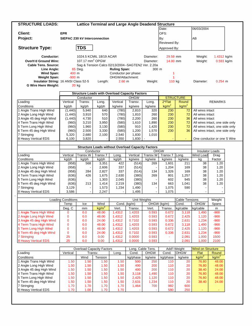
STRUCTURE LOADS: Lattice Terminal and Large Angle Deadend StructureDate:
Client: EPR OFS:Project: SIEPAC 230 kV Interconnection By: AB
Reviewed By:
Structure Type: TDS Approved By:
Conductor: 1024.5 KCMIL 18/19 ACAR Diameter: 29.59 mm Weight: 1.4312 kg/mOverh'd Ground Wire: 107.17 mm2 OPGW Diameter: 14.00 mm Weight: 0.593 kg/m
Cable Tens. Source: Sag & Tension Calcs 02/13/2004--SAGTEN2 Ver. 2.20aLine Angle: 65 Deg. Ruling Span: 300 mWind Span: 400 m Conductor per phase: 1
Weight Span: -900 m OHGW/Attachment: 1Insulator String: 16 ANSI Class 52-5 Length: 2.60 m Weight: 110 kg Diameter: 0.254 m
G Wire Hwre Weight: 20 kg
Structure Loads with Overload Capacity FactorsConductor OHGW
Loading Vertical Transv. Long. Vertical Transv. Long. 2*Flat RoundConditions kg/ph kg/ph kg/ph kg/wire kg/wire kg/wire kg/m2 kg/m2
1 Angle Trans High Wind (1,440) 5,940 640 (780) 2,810 320 230 72 All wires intact2 Angle Long High Wind (1,440) 3,910 570 (780) 1,810 260 230 72 All wires intact3 Angle 45 deg High Wind (1,440) 4,730 510 (780) 2,200 260 230 36 All wires intact4 Term Trans High Wind (960) 3,210 3,950 (580) 1,610 1,890 230 72 All wires intact, one side only5 Term Long High Wind (960) 1,960 3,130 (580) 910 1,420 230 72 All wires intact, one side only6 Term 45 deg High Wind (960) 2,500 3,330 (580) 1,200 1,570 230 36 All wires intact, one side only7 Stringing 5,320 2,680 2,100 2,540 1,830 1,010 8 Heavy Vertical EDS 6,100 3,820 - 2,550 1,830 - - - One conductor or one S Wire
Structure Loads without Overload Capacity Factors
Loading Vertical Transv.W Transv.T Long. Vertical Transv.W Transv.T Long. Wind Load DragConditions kg/ph kg/ph kg/ph kg/ph kg/wire kg/wire kg/wire kg/wire kg Factor1 Angle Trans High Wind (958) 568 3,351 422 (514) 269 1,601 211 38 1.202 Angle Long High Wind (958) - 2,606 337 (514) - 1,204 169 38 1.203 Angle 45 deg High Wind (958) 284 2,827 337 (514) 134 1,326 169 38 1.20 4 Term Trans High Wind (636) 426 1,675 2,630 (380) 269 801 1,257 38 1.20 5 Term Long High Wind (636) - 1,303 2,045 (380) - 602 945 38 1.20 6 Term 45 deg High Wind (636) 213 1,414 2,219 (380) 134 663 1,041 38 1.20 7 Stringing 3,129 - 1,573 1,234 1,490 - 1,075 590 - -8 Heavy Vertical EDS 3,586 - 2,247 - 1,495 - 1,075 - - -
- Loading Conditions Unit Weights Cable Tensions Weight
Temp Ice Wind Cond. (kg/m) OHGW (kg/m) Cond. OHGW SpansDeg. C mm kg/m2 Vert. Transv. Vert. Transv. kg/cable kg/cable m
1 Angle Trans High Wind 0 0.0 48.00 1.4312 1.4203 0.593 0.672 3,118 1,490 -9002 Angle Long High Wind 0 0.0 48.00 1.4312 1.4203 0.593 0.672 2,425 1,120 -9003 Angle 45 deg High Wind 0 0.0 24.00 1.4312 0.7102 0.593 0.336 2,631 1,234 -9004 Term Trans High Wind 0 0.0 48.00 1.4312 1.4203 0.593 0.672 3,118 1,490 -9005 Term Long High Wind 0 0.0 48.00 1.4312 1.4203 0.593 0.672 2,425 1,120 -9006 Term 45 deg High Wind 0 0.0 24.00 1.4312 0.7102 0.593 0.336 2,631 1,234 -9007 Stringing 25 0.0 0.00 1.4312 0.0000 0.593 - 2,091 1,000 15008 Heavy Vertical EDS 25 0.0 0.00 1.4312 0.0000 0.593 - 2,091 1,000 2100
Overload Capacity Factors Long. Cable Tens. Add'l Weight Wind on StructureLoading Vertical Transv. Long. Cond. OHGW Cond. OHGW Flat RoundConditions Wind Tension kg/phase kg/wire kg/phase kg/wire kg/m2 kg/m2
1 Angle Trans High Wind 1.50 1.50 1.50 1.50 500 250 110 20 76.80 48.00 2 Angle Long High Wind 1.50 1.50 1.50 1.50 400 200 110 20 76.80 48.00 3 Angle 45 deg High Wind 1.50 1.50 1.50 1.50 400 200 110 20 38.40 24.00 4 Term Trans High Wind 1.50 1.50 1.50 1.50 3,118 1,490 110 20 76.80 48.00 5 Term Long High Wind 1.50 1.50 1.50 1.50 2,425 1,120 110 20 76.80 48.00 6 Term 45 deg High Wind 1.50 1.50 1.50 1.50 2,631 1,234 110 20 38.40 24.00 7 Stringing 1.70 1.70 1.70 1.70 1,464 700 982 600 8 Heavy Vertical EDS 1.70 1.00 1.70 1.70 - - 580 250 - -
Conductor OHGW
06/03/2004
REMARKS
Insulator Loads
STRUCTURE

TORRES DE CIRCUITO DOBLE NORMALES

STRUCTURE LOADS: Lattice Normal Span Suspension StructureDate:
Client: EPR OFS:Project: SIEPAC 230 kV Interconnection By: AB
Reviewed By:
Structure Type: TD1 Approved By:
Conductor: 1024.5 KCMIL 18/19 ACAR Diameter: 29.59 mm Weight: 1.4312 kg/mOverh'd Ground Wire: 107.17 mm2 OPGW Diameter: 14.00 mm Weight: 0.593 kg/m
Cable Tens. Source: Sag & Tension Calcs 02/13/2004--SAGTEN2 Ver. 2.20aLine Angle: 2 Deg. Ruling Span: 300 mWind Span: 400 m Conductor per phase: 1
Weight Span: 600 m OHGW/Attachment: 1Insulator String: 16 ANSI Class 52-5 Length: 2.60 m Weight: 110 kg Diameter: 0.254 m
G Wire Hwre Weight: 10 kg
Structure Loads with Overload Capacity FactorsConductor OHGW
Loading Vertical Transv. Long. Vertical Transv. Long. 2*Flat RoundConditions kg/ph kg/ph kg/ph kg/wire kg/wire kg/wire kg/m2 kg/m2
1 Transverse High Wind 1,460 1,080 150 550 490 150 230 72 All wires intact2 Longitudinal High Wind 1,460 130 360 550 60 180 230 72 All wires intact3 High Wind 45 degree 1,460 630 300 550 270 180 230 36 All wires intact4 Long. Load Containment 1,170 90 2,510 440 50 1,200 - - Two cables (cond or S Wire)5 Longitudinal Unbalance 1,170 90 480 440 50 240 - - All wires intact, any combination6 Stringing 3,130 130 2,490 1,630 60 1,190 - - Anyone Conductor or S Wire7 Heavy Vertical 3,540 130 - 1,640 60 - - - Anyone Conductor or S Wire
0 - - - - - - - -
Structure Loads without Overload Capacity FactorsConductor OHGW
Loading Vertical Transv.W Transv.T Long. Vertical Transv.W Transv.T Long. Wind Load DragConditions kg/ph kg/ph kg/ph kg/ph kg/wire kg/wire kg/wire kg/wire kg Factor1 Transverse High Wind 969 568 109 100 366 269 52 100 38 1.202 Longitudinal High Wind 969 - 85 200 366 - 39 120 38 1.203 High Wind 45 degree 969 284 92 200 366 134 43 120 38 1.204 Long. Load Containment 969 - 73 2,091 366 - 35 1,000 - - 5 Longitudinal Unbalance 969 - 73 400 366 - 35 200 - - 6 Stringing 1,841 - 73 1,464 956 - 35 700 - - 7 Heavy Vertical 2,077 - 73 - 962 - 35 - - -
0 - - - - - - - - - -
Loading Conditions Unit Weights Cable Tensions WeightTemp Ice Wind Cond. (kg/m) OHGW (kg/m) Cond. OHGW Spans
Deg. C mm kg/m2 Vert. Transv. Vert. Transv. kg/cable kg/cable m1 Transverse High Wind 0 0.0 48.00 1.4312 1.4203 0.593 0.672 3,118 1,490 6002 Longitudinal High Wind 0 0.0 48.00 1.4312 1.4203 0.593 0.672 2,425 1,120 6003 High Wind 45 degree 0 0.0 24.00 1.4312 0.7102 0.593 0.336 2,631 1,234 6004 Long. Load Containment 25 0.0 0.00 1.4312 0.0000 0.593 - 2,091 1,000 6005 Longitudinal Unbalance 25 0.0 0.00 1.4312 0.0000 0.593 - 2,091 1,000 6006 Stringing 25 0.0 0.00 1.4312 0.0000 0.593 - 2,091 1,000 6007 Heavy Vertical 25 0.0 0.00 1.4312 0.0000 0.593 - 2,091 1,000 1200
Overload Capacity Factors Long. Cable Tens. Add'l Weight Wind on StructureLoading Vertical Transv. Long. Cond. OHGW Cond. OHGW Flat RoundConditions Wind Tension kg/phase kg/wire kg/phase kg/wire kg/m2 kg/m2
1 Transverse High Wind 1.50 1.50 1.50 1.50 100 100 110 10 76.80 48.00 2 Longitudinal High Wind 1.50 1.50 1.50 1.50 200 120 110 10 76.80 48.00 3 High Wind 45 degree 1.50 1.50 1.50 1.50 200 120 110 10 76.80 24.00 4 Long. Load Containment 1.20 1.20 1.20 1.20 2,091 1,000 110 10 - - 5 Longitudinal Unbalance 1.20 1.20 1.20 1.20 400 200 110 10 6 Stringing 1.70 1.70 1.70 1.70 1,464 700 982 600 - - 7 Heavy Vertical 1.70 1.70 1.70 1.70 - 1,000 360 250 - -
- - - - -
27/02/2004
REMARKS
Insulator Loads
STRUCTURE
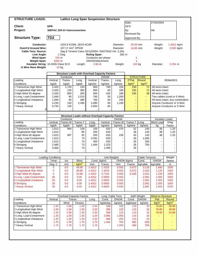
STRUCTURE LOADS: Lattice Long Span Suspension StructureDate:
Client: EPR OFS:Project: SIEPAC 230 kV Interconnection By: AB
Reviewed By:
Structure Type: TD2 Approved By:
Conductor: 1024.5 KCMIL 18/19 ACAR Diameter: 29.59 mm Weight: 1.4312 kg/mOverh'd Ground Wire: 107.17 mm2 OPGW Diameter: 14.00 mm Weight: 0.593 kg/m
Cable Tens. Source: Sag & Tension Calcs 02/13/2004--SAGTEN2 Ver. 2.20aLine Angle: 2 Deg. Ruling Span: 300 mWind Span: 700 m Conductor per phase: 1
Weight Span: 1050 m OHGW/Attachment: 1Insulator String: 16 ANSI Class 52-5 Length: 2.60 m Weight: 110 kg Diameter: 0.254 m
G Wire Hwre Weight: 10 kg
Structure Loads with Overload Capacity FactorsConductor OHGW
Loading Vertical Transv. Long. Vertical Transv. Long. 2*Flat RoundConditions kg/ph kg/ph kg/ph kg/wire kg/wire kg/wire kg/m2 kg/m2
1 Transverse High Wind 2,420 1,720 150 950 790 150 230 72 All wires intact2 Longitudinal High Wind 2,420 130 360 950 60 180 230 72 All wires intact3 High Wind 45 degree 2,420 950 300 950 420 180 230 36 All wires intact4 Long. Load Containment 1,940 90 2,510 760 50 1,200 - - Two cables (cond or S Wire)5 Longitudinal Unbalance 1,940 90 480 760 50 240 - - All wires intact, any combination6 Stringing 4,230 130 2,490 2,080 60 1,190 - - Anyone Conductor or S Wire7 Heavy Vertical 5,730 130 - 2,550 60 - - - Anyone Conductor or S Wire
0 - - - - - - - -
Structure Loads without Overload Capacity FactorsConductor OHGW
Loading Vertical Transv.W Transv.T Long. Vertical Transv.W Transv.T Long. Wind Load DragConditions kg/ph kg/ph kg/ph kg/ph kg/wire kg/wire kg/wire kg/wire kg Factor1 Transverse High Wind 1,613 994 109 100 633 470 52 100 38 1.202 Longitudinal High Wind 1,613 - 85 200 633 - 39 120 38 1.203 High Wind 45 degree 1,613 497 92 200 633 235 43 120 38 1.204 Long. Load Containment 1,613 - 73 2,091 633 - 35 1,000 - - 5 Longitudinal Unbalance 1,613 - 73 400 633 - 35 200 - - 6 Stringing 2,485 - 73 1,464 1,223 - 35 700 - - 7 Heavy Vertical 3,366 - 73 - 1,495 - 35 - - -
0 - - - - - - - - - -
Loading Conditions Unit Weights Cable Tensions WeightTemp Ice Wind Cond. (kg/m) OHGW (kg/m) Cond. OHGW Spans
Deg. C mm kg/m2 Vert. Transv. Vert. Transv. kg/cable kg/cable m1 Transverse High Wind 0 0.0 48.00 1.4312 1.4203 0.593 0.672 3,118 1,490 10502 Longitudinal High Wind 0 0.0 48.00 1.4312 1.4203 0.593 0.672 2,425 1,120 10503 High Wind 45 degree 0 0.0 24.00 1.4312 0.7102 0.593 0.336 2,631 1,234 10504 Long. Load Containment 25 0.0 0.00 1.4312 0.0000 0.593 - 2,091 1,000 10505 Longitudinal Unbalance 25 0.0 0.00 1.4312 0.0000 0.593 - 2,091 1,000 10506 Stringing 25 0.0 0.00 1.4312 0.0000 0.593 - 2,091 1,000 10507 Heavy Vertical 25 0.0 0.00 1.4312 0.0000 0.593 - 2,091 1,000 2100
Overload Capacity Factors Long. Cable Tens. Add'l Weight Wind on StructureLoading Vertical Transv. Long. Cond. OHGW Cond. OHGW Flat RoundConditions Wind Tension kg/phase kg/wire kg/phase kg/wire kg/m2 kg/m2
1 Transverse High Wind 1.50 1.50 1.50 1.50 100 100 110 10 76.80 48.00 2 Longitudinal High Wind 1.50 1.50 1.50 1.50 200 120 110 10 76.80 48.00 3 High Wind 45 degree 1.50 1.50 1.50 1.50 200 120 110 10 76.80 24.00 4 Long. Load Containment 1.20 1.20 1.20 1.20 2,091 1,000 110 10 - - 5 Longitudinal Unbalance 1.20 1.20 1.20 1.20 400 200 110 10 6 Stringing 1.70 1.70 1.70 1.70 1,464 700 982 600 - - 7 Heavy Vertical 1.70 1.70 1.70 1.70 - 1,000 360 250 - -
- - - - -
27/02/2004
REMARKS
Insulator Loads
STRUCTURE

STRUCTURE LOADS: Lattice Suspension and Small Angle StructureDate:
Client: EPR OFS:Project: SIEPAC 230 kV Interconnection By: AB
Reviewed By:
Structure Type: TDA Approved By:
Conductor: 1024.5 KCMIL 18/19 ACAR Diameter: 29.59 mm Weight: 1.4312 kg/mOverh'd Ground Wire: 107.17 mm2 OPGW Diameter: 14.00 mm Weight: 0.593 kg/m
Cable Tens. Source: Sag & Tension Calcs 02/13/2004--SAGTEN2 Ver. 2.20aLine Angle: 10 Deg. Ruling Span: 300 mWind Span: 400 m Conductor per phase: 1
Weight Span: 1050 m OHGW/Attachment: 1Insulator String: 16 ANSI Class 52-5 Length: 2.60 m Weight: 110 kg Diameter: 0.254 m
G Wire Hwre Weight: 10 kg
Structure Loads with Overload Capacity FactorsConductor OHGW
Loading Vertical Transv. Long. Vertical Transv. Long. 2*Flat RoundConditions kg/ph kg/ph kg/ph kg/wire kg/wire kg/wire kg/m2 kg/m2
1 Transverse High Wind 2,420 1,730 150 950 800 150 230 72 All wires intact2 Longitudinal High Wind 2,420 640 360 950 300 180 230 72 All wires intact3 High Wind 45 degree 2,420 1,180 300 950 530 180 230 36 All wires intact4 Long. Load Containment 1,940 440 2,510 760 210 1,200 - - Two cables (cond or S Wire)5 Longitudinal Unbalance 1,940 440 480 760 210 240 - - All wires intact, any combination6 Stringing 4,230 620 2,490 2,080 300 1,190 - - Anyone Conductor or S Wire7 Heavy Vertical 5,730 620 - 2,550 300 - - - Anyone Conductor or S Wire
0 - - - - - - - -
Structure Loads without Overload Capacity FactorsConductor OHGW
Loading Vertical Transv.W Transv.T Long. Vertical Transv.W Transv.T Long. Wind Load DragConditions kg/ph kg/ph kg/ph kg/ph kg/wire kg/wire kg/wire kg/wire kg Factor1 Transverse High Wind 1,613 568 544 100 633 269 260 100 38 1.202 Longitudinal High Wind 1,613 - 423 200 633 - 195 120 38 1.203 High Wind 45 degree 1,613 284 459 200 633 134 215 120 38 1.204 Long. Load Containment 1,613 - 364 2,091 633 - 174 1,000 - - 5 Longitudinal Unbalance 1,613 - 364 400 633 - 174 200 - - 6 Stringing 2,485 - 364 1,464 1,223 - 174 700 - - 7 Heavy Vertical 3,366 - 364 - 1,495 - 174 - - -
0 - - - - - - - - - -
Loading Conditions Unit Weights Cable Tensions WeightTemp Ice Wind Cond. (kg/m) OHGW (kg/m) Cond. OHGW Spans
Deg. C mm kg/m2 Vert. Transv. Vert. Transv. kg/cable kg/cable m1 Transverse High Wind 0 0.0 48.00 1.4312 1.4203 0.593 0.672 3,118 1,490 10502 Longitudinal High Wind 0 0.0 48.00 1.4312 1.4203 0.593 0.672 2,425 1,120 10503 High Wind 45 degree 0 0.0 24.00 1.4312 0.7102 0.593 0.336 2,631 1,234 10504 Long. Load Containment 25 0.0 0.00 1.4312 0.0000 0.593 - 2,091 1,000 10505 Longitudinal Unbalance 25 0.0 0.00 1.4312 0.0000 0.593 - 2,091 1,000 10506 Stringing 25 0.0 0.00 1.4312 0.0000 0.593 - 2,091 1,000 10507 Heavy Vertical 25 0.0 0.00 1.4312 0.0000 0.593 - 2,091 1,000 2100
Overload Capacity Factors Long. Cable Tens. Add'l Weight Wind on StructureLoading Vertical Transv. Long. Cond. OHGW Cond. OHGW Flat RoundConditions Wind Tension kg/phase kg/wire kg/phase kg/wire kg/m2 kg/m2
1 Transverse High Wind 1.50 1.50 1.50 1.50 100 100 110 10 76.80 48.00 2 Longitudinal High Wind 1.50 1.50 1.50 1.50 200 120 110 10 76.80 48.00 3 High Wind 45 degree 1.50 1.50 1.50 1.50 200 120 110 10 76.80 24.00 4 Long. Load Containment 1.20 1.20 1.20 1.20 2,091 1,000 110 10 - - 5 Longitudinal Unbalance 1.20 1.20 1.20 1.20 400 200 110 10 6 Stringing 1.70 1.70 1.70 1.70 1,464 700 982 600 - - 7 Heavy Vertical 1.70 1.70 1.70 1.70 - 1,000 360 250 - -
- - - - -
27/02/2004
REMARKS
Insulator Loads
STRUCTURE
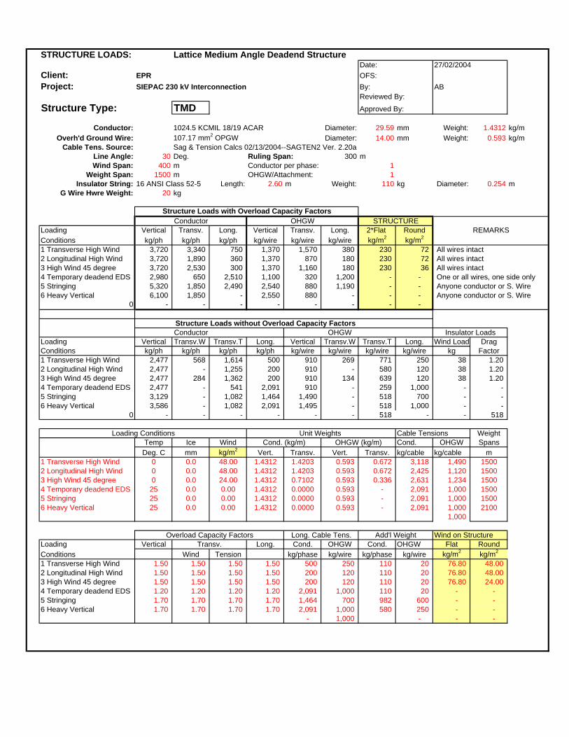
STRUCTURE LOADS: Lattice Medium Angle Deadend StructureDate:
Client: EPR OFS:Project: SIEPAC 230 kV Interconnection By: AB
Reviewed By:
Structure Type: TMD Approved By:
Conductor: 1024.5 KCMIL 18/19 ACAR Diameter: 29.59 mm Weight: 1.4312 kg/mOverh'd Ground Wire: 107.17 mm2 OPGW Diameter: 14.00 mm Weight: 0.593 kg/m
Cable Tens. Source: Sag & Tension Calcs 02/13/2004--SAGTEN2 Ver. 2.20aLine Angle: 30 Deg. Ruling Span: 300 mWind Span: 400 m Conductor per phase: 1
Weight Span: 1500 m OHGW/Attachment: 1Insulator String: 16 ANSI Class 52-5 Length: 2.60 m Weight: 110 kg Diameter: 0.254 m
G Wire Hwre Weight: 20 kg
Structure Loads with Overload Capacity FactorsConductor OHGW
Loading Vertical Transv. Long. Vertical Transv. Long. 2*Flat RoundConditions kg/ph kg/ph kg/ph kg/wire kg/wire kg/wire kg/m2 kg/m2
1 Transverse High Wind 3,720 3,340 750 1,370 1,570 380 230 72 All wires intact2 Longitudinal High Wind 3,720 1,890 360 1,370 870 180 230 72 All wires intact3 High Wind 45 degree 3,720 2,530 300 1,370 1,160 180 230 36 All wires intact4 Temporary deadend EDS 2,980 650 2,510 1,100 320 1,200 - - One or all wires, one side only5 Stringing 5,320 1,850 2,490 2,540 880 1,190 - - Anyone conductor or S. Wire6 Heavy Vertical 6,100 1,850 - 2,550 880 - - - Anyone conductor or S. Wire
0 - - - - - - - -
Structure Loads without Overload Capacity FactorsConductor OHGW
Loading Vertical Transv.W Transv.T Long. Vertical Transv.W Transv.T Long. Wind Load DragConditions kg/ph kg/ph kg/ph kg/ph kg/wire kg/wire kg/wire kg/wire kg Factor1 Transverse High Wind 2,477 568 1,614 500 910 269 771 250 38 1.202 Longitudinal High Wind 2,477 - 1,255 200 910 - 580 120 38 1.203 High Wind 45 degree 2,477 284 1,362 200 910 134 639 120 38 1.204 Temporary deadend EDS 2,477 - 541 2,091 910 - 259 1,000 - - 5 Stringing 3,129 - 1,082 1,464 1,490 - 518 700 - - 6 Heavy Vertical 3,586 - 1,082 2,091 1,495 - 518 1,000 - -
0 - - - - - - 518 - - 518
Loading Conditions Unit Weights Cable Tensions WeightTemp Ice Wind Cond. (kg/m) OHGW (kg/m) Cond. OHGW Spans
Deg. C mm kg/m2 Vert. Transv. Vert. Transv. kg/cable kg/cable m1 Transverse High Wind 0 0.0 48.00 1.4312 1.4203 0.593 0.672 3,118 1,490 15002 Longitudinal High Wind 0 0.0 48.00 1.4312 1.4203 0.593 0.672 2,425 1,120 15003 High Wind 45 degree 0 0.0 24.00 1.4312 0.7102 0.593 0.336 2,631 1,234 15004 Temporary deadend EDS 25 0.0 0.00 1.4312 0.0000 0.593 - 2,091 1,000 15005 Stringing 25 0.0 0.00 1.4312 0.0000 0.593 - 2,091 1,000 15006 Heavy Vertical 25 0.0 0.00 1.4312 0.0000 0.593 - 2,091 1,000 2100
1,000
Overload Capacity Factors Long. Cable Tens. Add'l Weight Wind on StructureLoading Vertical Transv. Long. Cond. OHGW Cond. OHGW Flat RoundConditions Wind Tension kg/phase kg/wire kg/phase kg/wire kg/m2 kg/m2
1 Transverse High Wind 1.50 1.50 1.50 1.50 500 250 110 20 76.80 48.00 2 Longitudinal High Wind 1.50 1.50 1.50 1.50 200 120 110 20 76.80 48.00 3 High Wind 45 degree 1.50 1.50 1.50 1.50 200 120 110 20 76.80 24.00 4 Temporary deadend EDS 1.20 1.20 1.20 1.20 2,091 1,000 110 20 - - 5 Stringing 1.70 1.70 1.70 1.70 1,464 700 982 600 - - 6 Heavy Vertical 1.70 1.70 1.70 1.70 2,091 1,000 580 250 - -
- 1,000 - - -
27/02/2004
REMARKS
Insulator Loads
STRUCTURE
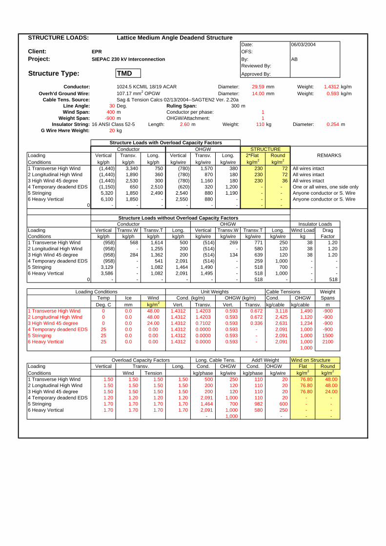
STRUCTURE LOADS: Lattice Medium Angle Deadend StructureDate:
Client: EPR OFS:Project: SIEPAC 230 kV Interconnection By: AB
Reviewed By:
Structure Type: TMD Approved By:
Conductor: 1024.5 KCMIL 18/19 ACAR Diameter: 29.59 mm Weight: 1.4312 kg/mOverh'd Ground Wire: 107.17 mm2 OPGW Diameter: 14.00 mm Weight: 0.593 kg/m
Cable Tens. Source: Sag & Tension Calcs 02/13/2004--SAGTEN2 Ver. 2.20aLine Angle: 30 Deg. Ruling Span: 300 mWind Span: 400 m Conductor per phase: 1
Weight Span: -900 m OHGW/Attachment: 1Insulator String: 16 ANSI Class 52-5 Length: 2.60 m Weight: 110 kg Diameter: 0.254 m
G Wire Hwre Weight: 20 kg
Structure Loads with Overload Capacity FactorsConductor OHGW
Loading Vertical Transv. Long. Vertical Transv. Long. 2*Flat RoundConditions kg/ph kg/ph kg/ph kg/wire kg/wire kg/wire kg/m2 kg/m2
1 Transverse High Wind (1,440) 3,340 750 (780) 1,570 380 230 72 All wires intact2 Longitudinal High Wind (1,440) 1,890 360 (780) 870 180 230 72 All wires intact3 High Wind 45 degree (1,440) 2,530 300 (780) 1,160 180 230 36 All wires intact4 Temporary deadend EDS (1,150) 650 2,510 (620) 320 1,200 - - One or all wires, one side only5 Stringing 5,320 1,850 2,490 2,540 880 1,190 - - Anyone conductor or S. Wire6 Heavy Vertical 6,100 1,850 - 2,550 880 - - - Anyone conductor or S. Wire
0 - - - - - - - -
Structure Loads without Overload Capacity FactorsConductor OHGW
Loading Vertical Transv.W Transv.T Long. Vertical Transv.W Transv.T Long. Wind Load DragConditions kg/ph kg/ph kg/ph kg/ph kg/wire kg/wire kg/wire kg/wire kg Factor1 Transverse High Wind (958) 568 1,614 500 (514) 269 771 250 38 1.202 Longitudinal High Wind (958) - 1,255 200 (514) - 580 120 38 1.203 High Wind 45 degree (958) 284 1,362 200 (514) 134 639 120 38 1.204 Temporary deadend EDS (958) - 541 2,091 (514) - 259 1,000 - - 5 Stringing 3,129 - 1,082 1,464 1,490 - 518 700 - - 6 Heavy Vertical 3,586 - 1,082 2,091 1,495 - 518 1,000 - -
0 - - - - - - 518 - - 518
Loading Conditions Unit Weights Cable Tensions WeightTemp Ice Wind Cond. (kg/m) OHGW (kg/m) Cond. OHGW SpansDeg. C mm kg/m2 Vert. Transv. Vert. Transv. kg/cable kg/cable m
1 Transverse High Wind 0 0.0 48.00 1.4312 1.4203 0.593 0.672 3,118 1,490 -9002 Longitudinal High Wind 0 0.0 48.00 1.4312 1.4203 0.593 0.672 2,425 1,120 -9003 High Wind 45 degree 0 0.0 24.00 1.4312 0.7102 0.593 0.336 2,631 1,234 -9004 Temporary deadend EDS 25 0.0 0.00 1.4312 0.0000 0.593 - 2,091 1,000 -9005 Stringing 25 0.0 0.00 1.4312 0.0000 0.593 - 2,091 1,000 15006 Heavy Vertical 25 0.0 0.00 1.4312 0.0000 0.593 - 2,091 1,000 2100
1,000
Overload Capacity Factors Long. Cable Tens. Add'l Weight Wind on StructureLoading Vertical Transv. Long. Cond. OHGW Cond. OHGW Flat RoundConditions Wind Tension kg/phase kg/wire kg/phase kg/wire kg/m2 kg/m2
1 Transverse High Wind 1.50 1.50 1.50 1.50 500 250 110 20 76.80 48.00 2 Longitudinal High Wind 1.50 1.50 1.50 1.50 200 120 110 20 76.80 48.00 3 High Wind 45 degree 1.50 1.50 1.50 1.50 200 120 110 20 76.80 24.00 4 Temporary deadend EDS 1.20 1.20 1.20 1.20 2,091 1,000 110 20 - - 5 Stringing 1.70 1.70 1.70 1.70 1,464 700 982 600 - - 6 Heavy Vertical 1.70 1.70 1.70 1.70 2,091 1,000 580 250 - -
- 1,000 - - -
06/03/2004
REMARKS
Insulator Loads
STRUCTURE

STRUCTURE LOADS: Lattice Terminal and Large Angle Deadend StructureDate:
Client: EPR OFS:Project: SIEPAC 230 kV Interconnection By: AB
Reviewed By:
Structure Type: TDD Approved By:
Conductor: 1024.5 KCMIL 18/19 ACAR Diameter: 29.59 mm Weight: 1.4312 kg/mOverh'd Ground Wire: 107.17 mm2 OPGW Diameter: 14.00 mm Weight: 0.593 kg/m
Cable Tens. Source: Sag & Tension Calcs 02/13/2004--SAGTEN2 Ver. 2.20aLine Angle: 65 Deg. Ruling Span: 300 mWind Span: 400 m Conductor per phase: 1
Weight Span: 1500 m OHGW/Attachment: 1Insulator String: 16 ANSI Class 52-5 Length: 2.60 m Weight: 110 kg Diameter: 0.254 m
G Wire Hwre Weight: 20 kg
Structure Loads with Overload Capacity FactorsConductor OHGW
Loading Vertical Transv. Long. Vertical Transv. Long. 2*Flat RoundConditions kg/ph kg/ph kg/ph kg/wire kg/wire kg/wire kg/m2 kg/m2
1 Angle Trans High Wind 3,720 5,940 640 1,370 2,810 320 230 72 All wires intact2 Angle Long High Wind 3,720 3,910 570 1,370 1,810 260 230 72 All wires intact3 Angle 45 deg High Wind 3,720 4,730 510 1,370 2,200 260 230 36 All wires intact4 Term Trans High Wind 2,920 3,210 3,950 1,040 1,610 1,890 230 72 All wires intact, one side only5 Term Long High Wind 2,920 1,960 3,130 1,040 910 1,420 230 72 All wires intact, one side only6 Term 45 deg High Wind 2,920 2,500 3,330 1,040 1,200 1,570 230 36 All wires intact, one side only7 Stringing 5,320 2,680 2,100 2,540 1,830 1,010 One conductor or one S Wire8 Heavy Vertical EDS 6,100 3,820 - 2,550 1,830 - - - One conductor or one S Wire
Structure Loads without Overload Capacity Factors
Loading Vertical Transv.W Transv.T Long. Vertical Transv.W Transv.T Long. Wind Load DragConditions kg/ph kg/ph kg/ph kg/ph kg/wire kg/wire kg/wire kg/wire kg Factor1 Angle Trans High Wind 2,477 568 3,351 422 910 269 1,601 211 38 1.202 Angle Long High Wind 2,477 - 2,606 337 910 - 1,204 169 38 1.203 Angle 45 deg High Wind 2,477 284 2,827 337 910 134 1,326 169 38 1.20 4 Term Trans High Wind 1,940 426 1,675 2,630 687 269 801 1,257 38 1.20 5 Term Long High Wind 1,940 - 1,303 2,045 687 - 602 945 38 1.20 6 Term 45 deg High Wind 1,940 213 1,414 2,219 687 134 663 1,041 38 1.20 7 Stringing 3,129 - 1,573 1,234 1,490 - 1,075 590 - -8 Heavy Vertical EDS 3,586 - 2,247 - 1,495 - 1,075 - - -
- Loading Conditions Unit Weights Cable Tensions Weight
Temp Ice Wind Cond. (kg/m) OHGW (kg/m) Cond. OHGW SpansDeg. C mm kg/m2 Vert. Transv. Vert. Transv. kg/cable kg/cable m
1 Angle Trans High Wind 0 0.0 48.00 1.4312 1.4203 0.593 0.672 3,118 1,490 15002 Angle Long High Wind 0 0.0 48.00 1.4312 1.4203 0.593 0.672 2,425 1,120 15003 Angle 45 deg High Wind 0 0.0 24.00 1.4312 0.7102 0.593 0.336 2,631 1,234 15004 Term Trans High Wind 0 0.0 48.00 1.4312 1.4203 0.593 0.672 3,118 1,490 15005 Term Long High Wind 0 0.0 48.00 1.4312 1.4203 0.593 0.672 2,425 1,120 15006 Term 45 deg High Wind 0 0.0 24.00 1.4312 0.7102 0.593 0.336 2,631 1,234 15007 Stringing 25 0.0 0.00 1.4312 0.0000 0.593 - 2,091 1,000 15008 Heavy Vertical EDS 25 0.0 0.00 1.4312 0.0000 0.593 - 2,091 1,000 2100
Overload Capacity Factors Long. Cable Tens. Add'l Weight Wind on StructureLoading Vertical Transv. Long. Cond. OHGW Cond. OHGW Flat RoundConditions Wind Tension kg/phase kg/wire kg/phase kg/wire kg/m2 kg/m2
1 Angle Trans High Wind 1.50 1.50 1.50 1.50 500 250 110 20 76.80 48.00 2 Angle Long High Wind 1.50 1.50 1.50 1.50 400 200 110 20 76.80 48.00 3 Angle 45 deg High Wind 1.50 1.50 1.50 1.50 400 200 110 20 38.40 24.00 4 Term Trans High Wind 1.50 1.50 1.50 1.50 3,118 1,490 110 20 76.80 48.00 5 Term Long High Wind 1.50 1.50 1.50 1.50 2,425 1,120 110 20 76.80 48.00 6 Term 45 deg High Wind 1.50 1.50 1.50 1.50 2,631 1,234 110 20 38.40 24.00 7 Stringing 1.70 1.70 1.70 1.70 1,464 700 982 600 8 Heavy Vertical EDS 1.70 1.00 1.70 1.70 - - 580 250 - -
Conductor OHGW
27/02/2004
REMARKS
Insulator Loads
STRUCTURE

STRUCTURE LOADS: Lattice Terminal and Large Angle Deadend StructureDate:
Client: EPR OFS:Project: SIEPAC 230 kV Interconnection By: AB
Reviewed By:
Structure Type: TDD Approved By:
Conductor: 1024.5 KCMIL 18/19 ACAR Diameter: 29.59 mm Weight: 1.4312 kg/mOverh'd Ground Wire: 107.17 mm2 OPGW Diameter: 14.00 mm Weight: 0.593 kg/m
Cable Tens. Source: Sag & Tension Calcs 02/13/2004--SAGTEN2 Ver. 2.20aLine Angle: 0 Deg. Ruling Span: 300 mWind Span: 400 m Conductor per phase: 1
Weight Span: 1500 m OHGW/Attachment: 1Insulator String: 16 ANSI Class 52-5 Length: 2.60 m Weight: 110 kg Diameter: 0.254 m
G Wire Hwre Weight: 20 kg
Structure Loads with Overload Capacity FactorsConductor OHGW
Loading Vertical Transv. Long. Vertical Transv. Long. 2*Flat RoundConditions kg/ph kg/ph kg/ph kg/wire kg/wire kg/wire kg/m2 kg/m2
1 Angle Trans High Wind 3,720 910 750 1,370 410 380 230 72 All wires intact2 Angle Long High Wind 3,720 - 660 1,370 - 300 230 72 All wires intact3 Angle 45 deg High Wind 3,720 490 600 1,370 210 300 230 36 All wires intact4 Term Trans High Wind 2,920 700 4,680 1,040 410 2,240 230 72 All wires intact, one side only5 Term Long High Wind 2,920 - 3,700 1,040 - 1,680 230 72 All wires intact, one side only6 Term 45 deg High Wind 2,920 380 3,950 1,040 210 1,860 230 36 All wires intact, one side only7 Stringing 5,320 - 2,490 2,540 - 1,190 One conductor or one S Wire8 Heavy Vertical EDS 6,100 - - 2,550 - - - - One conductor or one S Wire
Structure Loads without Overload Capacity Factors
Loading Vertical Transv.W Transv.T Long. Vertical Transv.W Transv.T Long. Wind Load DragConditions kg/ph kg/ph kg/ph kg/ph kg/wire kg/wire kg/wire kg/wire kg Factor1 Angle Trans High Wind 2,477 568 - 500 910 269 - 250 38 1.202 Angle Long High Wind 2,477 - - 400 910 - - 200 38 1.203 Angle 45 deg High Wind 2,477 284 - 400 910 134 - 200 38 1.20 4 Term Trans High Wind 1,940 426 - 3,118 687 269 - 1,490 38 1.20 5 Term Long High Wind 1,940 - - 2,425 687 - - 1,120 38 1.20 6 Term 45 deg High Wind 1,940 213 - 2,631 687 134 - 1,234 38 1.20 7 Stringing 3,129 - - 1,464 1,490 - - 700 8 Heavy Vertical EDS 3,586 - - - 1,495 - - - - -
- Loading Conditions Unit Weights Cable Tensions Weight
Temp Ice Wind Cond. (kg/m) OHGW (kg/m) Cond. OHGW SpansDeg. C mm kg/m2 Vert. Transv. Vert. Transv. kg/cable kg/cable m
1 Angle Trans High Wind 0 0.0 48.00 1.4312 1.4203 0.593 0.672 3,118 1,490 15002 Angle Long High Wind 0 0.0 48.00 1.4312 1.4203 0.593 0.672 2,425 1,120 15003 Angle 45 deg High Wind 0 0.0 24.00 1.4312 0.7102 0.593 0.336 2,631 1,234 15004 Term Trans High Wind 0 0.0 48.00 1.4312 1.4203 0.593 0.672 3,118 1,490 15005 Term Long High Wind 0 0.0 48.00 1.4312 1.4203 0.593 0.672 2,425 1,120 15006 Term 45 deg High Wind 0 0.0 24.00 1.4312 0.7102 0.593 0.336 2,631 1,234 15007 Stringing 25 0.0 0.00 1.4312 0.0000 0.593 - 2,091 1,000 15008 Heavy Vertical EDS 25 0.0 0.00 1.4312 0.0000 0.593 - 2,091 1,000 2100
Overload Capacity Factors Long. Cable Tens. Add'l Weight Wind on StructureLoading Vertical Transv. Long. Cond. OHGW Cond. OHGW Flat RoundConditions Wind Tension kg/phase kg/wire kg/phase kg/wire kg/m2 kg/m2
1 Angle Trans High Wind 1.50 1.50 1.50 1.50 500 250 110 20 76.80 48.00 2 Angle Long High Wind 1.50 1.50 1.50 1.50 400 200 110 20 76.80 48.00 3 Angle 45 deg High Wind 1.50 1.50 1.50 1.50 400 200 110 20 38.40 24.00 4 Term Trans High Wind 1.50 1.50 1.50 1.50 3,118 1,490 110 20 76.80 48.00 5 Term Long High Wind 1.50 1.50 1.50 1.50 2,425 1,120 110 20 76.80 48.00 6 Term 45 deg High Wind 1.50 1.50 1.50 1.50 2,631 1,234 110 20 38.40 24.00 7 Stringing 1.70 1.70 1.70 1.70 1,464 700 982 600 8 Heavy Vertical EDS 1.70 1.00 1.70 1.70 - - 580 250 - -
29% Tension de LineaCargas Adicionales Vano Subestacion Conductor H Guardia Vano: 150 m
Tension Max Viento Transversal: 910 kg 440 kgTension Max Viento Longitudinal: 710 kg 330 kg
Tension Max Viento 45o: 770 kg 360 kg
Loading Vertical Transv.W Transv.T Long. Vertical Transv.W Transv.T Long.Conditions kg/ph kg/ph kg/ph kg/ph kg/wire kg/wire kg/wire kg/wire1 Angle Trans High Wind - - - - - - - -2 Angle Long High Wind - - - - - - - -3 Angle 45 deg High Wind - - - - - - - -4 Term Trans High Wind 250 - 1070 - 170 - 500 -5 Term Long High Wind 250 - 1370 160 170 - 660 806 Term 45 deg High Wind 250 - 1160 80 170 - 540 407 Stringing - - - - - - - -8 Heavy Vertical EDS - - - - - - - -
Conductor OHGW
Conductor OHGW
27/02/2004
REMARKS
Insulator Loads
STRUCTURE
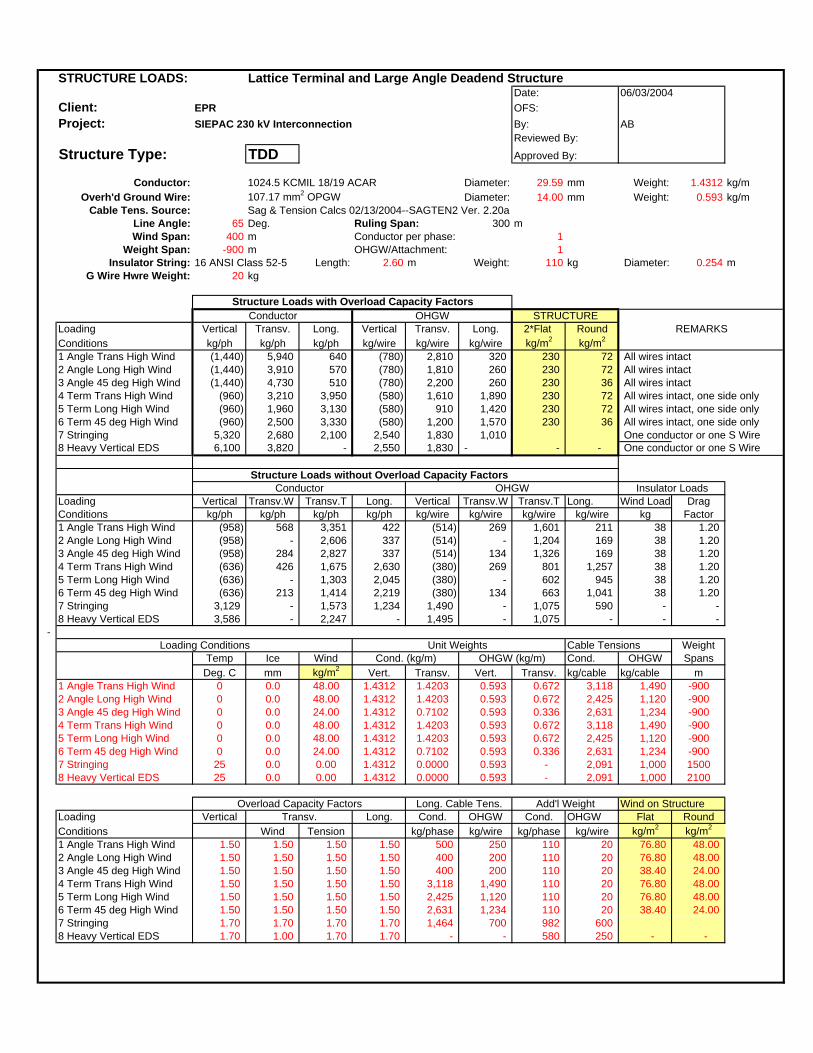
STRUCTURE LOADS: Lattice Terminal and Large Angle Deadend StructureDate:
Client: EPR OFS:Project: SIEPAC 230 kV Interconnection By: AB
Reviewed By:
Structure Type: TDD Approved By:
Conductor: 1024.5 KCMIL 18/19 ACAR Diameter: 29.59 mm Weight: 1.4312 kg/mOverh'd Ground Wire: 107.17 mm2 OPGW Diameter: 14.00 mm Weight: 0.593 kg/m
Cable Tens. Source: Sag & Tension Calcs 02/13/2004--SAGTEN2 Ver. 2.20aLine Angle: 65 Deg. Ruling Span: 300 mWind Span: 400 m Conductor per phase: 1
Weight Span: -900 m OHGW/Attachment: 1Insulator String: 16 ANSI Class 52-5 Length: 2.60 m Weight: 110 kg Diameter: 0.254 m
G Wire Hwre Weight: 20 kg
Structure Loads with Overload Capacity FactorsConductor OHGW
Loading Vertical Transv. Long. Vertical Transv. Long. 2*Flat RoundConditions kg/ph kg/ph kg/ph kg/wire kg/wire kg/wire kg/m2 kg/m2
1 Angle Trans High Wind (1,440) 5,940 640 (780) 2,810 320 230 72 All wires intact2 Angle Long High Wind (1,440) 3,910 570 (780) 1,810 260 230 72 All wires intact3 Angle 45 deg High Wind (1,440) 4,730 510 (780) 2,200 260 230 36 All wires intact4 Term Trans High Wind (960) 3,210 3,950 (580) 1,610 1,890 230 72 All wires intact, one side only5 Term Long High Wind (960) 1,960 3,130 (580) 910 1,420 230 72 All wires intact, one side only6 Term 45 deg High Wind (960) 2,500 3,330 (580) 1,200 1,570 230 36 All wires intact, one side only7 Stringing 5,320 2,680 2,100 2,540 1,830 1,010 One conductor or one S Wire8 Heavy Vertical EDS 6,100 3,820 - 2,550 1,830 - - - One conductor or one S Wire
Structure Loads without Overload Capacity Factors
Loading Vertical Transv.W Transv.T Long. Vertical Transv.W Transv.T Long. Wind Load DragConditions kg/ph kg/ph kg/ph kg/ph kg/wire kg/wire kg/wire kg/wire kg Factor1 Angle Trans High Wind (958) 568 3,351 422 (514) 269 1,601 211 38 1.202 Angle Long High Wind (958) - 2,606 337 (514) - 1,204 169 38 1.203 Angle 45 deg High Wind (958) 284 2,827 337 (514) 134 1,326 169 38 1.20 4 Term Trans High Wind (636) 426 1,675 2,630 (380) 269 801 1,257 38 1.20 5 Term Long High Wind (636) - 1,303 2,045 (380) - 602 945 38 1.20 6 Term 45 deg High Wind (636) 213 1,414 2,219 (380) 134 663 1,041 38 1.20 7 Stringing 3,129 - 1,573 1,234 1,490 - 1,075 590 - -8 Heavy Vertical EDS 3,586 - 2,247 - 1,495 - 1,075 - - -
- Loading Conditions Unit Weights Cable Tensions Weight
Temp Ice Wind Cond. (kg/m) OHGW (kg/m) Cond. OHGW SpansDeg. C mm kg/m2 Vert. Transv. Vert. Transv. kg/cable kg/cable m
1 Angle Trans High Wind 0 0.0 48.00 1.4312 1.4203 0.593 0.672 3,118 1,490 -9002 Angle Long High Wind 0 0.0 48.00 1.4312 1.4203 0.593 0.672 2,425 1,120 -9003 Angle 45 deg High Wind 0 0.0 24.00 1.4312 0.7102 0.593 0.336 2,631 1,234 -9004 Term Trans High Wind 0 0.0 48.00 1.4312 1.4203 0.593 0.672 3,118 1,490 -9005 Term Long High Wind 0 0.0 48.00 1.4312 1.4203 0.593 0.672 2,425 1,120 -9006 Term 45 deg High Wind 0 0.0 24.00 1.4312 0.7102 0.593 0.336 2,631 1,234 -9007 Stringing 25 0.0 0.00 1.4312 0.0000 0.593 - 2,091 1,000 15008 Heavy Vertical EDS 25 0.0 0.00 1.4312 0.0000 0.593 - 2,091 1,000 2100
Overload Capacity Factors Long. Cable Tens. Add'l Weight Wind on StructureLoading Vertical Transv. Long. Cond. OHGW Cond. OHGW Flat RoundConditions Wind Tension kg/phase kg/wire kg/phase kg/wire kg/m2 kg/m2
1 Angle Trans High Wind 1.50 1.50 1.50 1.50 500 250 110 20 76.80 48.00 2 Angle Long High Wind 1.50 1.50 1.50 1.50 400 200 110 20 76.80 48.00 3 Angle 45 deg High Wind 1.50 1.50 1.50 1.50 400 200 110 20 38.40 24.00 4 Term Trans High Wind 1.50 1.50 1.50 1.50 3,118 1,490 110 20 76.80 48.00 5 Term Long High Wind 1.50 1.50 1.50 1.50 2,425 1,120 110 20 76.80 48.00 6 Term 45 deg High Wind 1.50 1.50 1.50 1.50 2,631 1,234 110 20 38.40 24.00 7 Stringing 1.70 1.70 1.70 1.70 1,464 700 982 600 8 Heavy Vertical EDS 1.70 1.00 1.70 1.70 - - 580 250 - -
Conductor OHGW
06/03/2004
REMARKS
Insulator Loads
STRUCTURE
TORRES DE BASE ESTRECHA
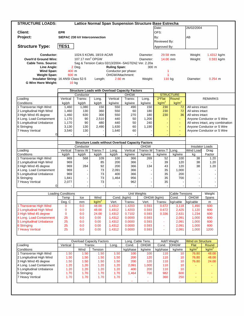
STRUCTURE LOADS: Lattice Normal Span Suspension Structure Base EstrechaDate:
Client: EPR OFS:Project: SIEPAC 230 kV Interconnection By: AB
Reviewed By:
Structure Type: TES1 Approved By:
Conductor: 1024.5 KCMIL 18/19 ACAR Diameter: 29.59 mm Weight: 1.4312 kg/mOverh'd Ground Wire: 107.17 mm2 OPGW Diameter: 14.00 mm Weight: 0.593 kg/m
Cable Tens. Source: Sag & Tension Calcs 02/13/2004--SAGTEN2 Ver. 2.20aLine Angle: 2 Deg. Ruling Span: 300 mWind Span: 400 m Conductor per phase: 1
Weight Span: 600 m OHGW/Attachment: 1Insulator String: 16 ANSI Class 52-5 Length: 2.60 m Weight: 110 kg Diameter: 0.254 m
G Wire Hwre Weight: 10 kg
Structure Loads with Overload Capacity FactorsConductor OHGW
Loading Vertical Transv. Long. Vertical Transv. Long. 2*Flat RoundConditions kg/ph kg/ph kg/ph kg/wire kg/wire kg/wire kg/m2 kg/m2
1 Transverse High Wind 1,460 1,080 150 550 490 150 230 72 All wires intact2 Longitudinal High Wind 1,460 130 360 550 60 180 230 72 All wires intact3 High Wind 45 degree 1,460 630 300 550 270 180 230 36 All wires intact4 Long. Load Containment 1,170 90 2,510 440 50 1,200 - - Anyone Conductor or S Wire5 Longitudinal Unbalance 1,170 90 480 440 50 240 - - All wires intact, any combination6 Stringing 3,130 130 2,490 1,630 60 1,190 - - Anyone Conductor or S Wire7 Heavy Vertical 3,540 130 - 1,640 60 - - - Anyone Conductor or S Wire
0 - - - - - - - -
Structure Loads without Overload Capacity FactorsConductor OHGW
Loading Vertical Transv.W Transv.T Long. Vertical Transv.W Transv.T Long. Wind Load DragConditions kg/ph kg/ph kg/ph kg/ph kg/wire kg/wire kg/wire kg/wire kg Factor1 Transverse High Wind 969 568 109 100 366 269 52 100 38 1.202 Longitudinal High Wind 969 - 85 200 366 - 39 120 38 1.203 High Wind 45 degree 969 284 92 200 366 134 43 120 38 1.204 Long. Load Containment 969 - 73 2,091 366 - 35 1,000 - - 5 Longitudinal Unbalance 969 - 73 400 366 - 35 200 - - 6 Stringing 1,841 - 73 1,464 956 - 35 700 - - 7 Heavy Vertical 2,077 - 73 - 962 - 35 - - -
0 - - - - - - - - - -
Loading Conditions Unit Weights Cable Tensions WeightTemp Ice Wind Cond. (kg/m) OHGW (kg/m) Cond. OHGW Spans
Deg. C mm kg/m2 Vert. Transv. Vert. Transv. kg/cable kg/cable m1 Transverse High Wind 0 0.0 48.00 1.4312 1.4203 0.593 0.672 3,118 1,490 6002 Longitudinal High Wind 0 0.0 48.00 1.4312 1.4203 0.593 0.672 2,425 1,120 6003 High Wind 45 degree 0 0.0 24.00 1.4312 0.7102 0.593 0.336 2,631 1,234 6004 Long. Load Containment 25 0.0 0.00 1.4312 0.0000 0.593 - 2,091 1,000 6005 Longitudinal Unbalance 25 0.0 0.00 1.4312 0.0000 0.593 - 2,091 1,000 6006 Stringing 25 0.0 0.00 1.4312 0.0000 0.593 - 2,091 1,000 6007 Heavy Vertical 25 0.0 0.00 1.4312 0.0000 0.593 - 2,091 1,000 1200
Overload Capacity Factors Long. Cable Tens. Add'l Weight Wind on StructureLoading Vertical Transv. Long. Cond. OHGW Cond. OHGW Flat RoundConditions Wind Tension kg/phase kg/wire kg/phase kg/wire kg/m2 kg/m2
1 Transverse High Wind 1.50 1.50 1.50 1.50 100 100 110 10 76.80 48.00 2 Longitudinal High Wind 1.50 1.50 1.50 1.50 200 120 110 10 76.80 48.00 3 High Wind 45 degree 1.50 1.50 1.50 1.50 200 120 110 10 76.80 24.00 4 Long. Load Containment 1.20 1.20 1.20 1.20 2,091 1,000 110 10 - - 5 Longitudinal Unbalance 1.20 1.20 1.20 1.20 400 200 110 10 6 Stringing 1.70 1.70 1.70 1.70 1,464 700 982 600 - - 7 Heavy Vertical 1.70 1.70 1.70 1.70 - - 360 250 - -
- - - - -
26/02/2004
REMARKS
Insulator Loads
STRUCTURE

STRUCTURE LOADS: Lattice Medium Angle Deadend Structure Base EstrechaDate:
Client: EPR OFS:Project: SIEPAC 230 kV Interconnection By: AB
Reviewed By:
Structure Type: TEMS Approved By:
Conductor: 1024.5 KCMIL 18/19 ACAR Diameter: 29.59 mm Weight: 1.4312 kg/mOverh'd Ground Wire: 107.17 mm2 OPGW Diameter: 14.00 mm Weight: 0.593 kg/m
Cable Tens. Source: Sag & Tension Calcs 02/13/2004--SAGTEN2 Ver. 2.20aLine Angle: 30 Deg. Ruling Span: 300 mWind Span: 400 m Conductor per phase: 1
Weight Span: 1500 m OHGW/Attachment: 1Insulator String: 16 ANSI Class 52-5 Length: 2.60 m Weight: 110 kg Diameter: 0.254 m
G Wire Hwre Weight: 20 kg
Structure Loads with Overload Capacity FactorsConductor OHGW
Loading Vertical Transv. Long. Vertical Transv. Long. 2*Flat RoundConditions kg/ph kg/ph kg/ph kg/wire kg/wire kg/wire kg/m2 kg/m2
1 Transverse High Wind 3,720 3,340 750 1,370 1,570 380 230 72 All wires intact2 Longitudinal High Wind 3,720 1,890 360 1,370 870 180 230 72 All wires intact3 High Wind 45 degree 3,720 2,530 300 1,370 1,160 180 230 36 All wires intact4 Temporary deadend EDS 2,980 650 2,510 1,100 320 1,200 - - One or all wires, one side only5 Stringing 5,320 1,850 2,490 2,540 880 1,190 - - Anyone conductor or S. Wire6 Heavy Vertical 6,100 1,850 - 2,550 880 - - - Anyone conductor or S. Wire
0 - - - - - - - -
Structure Loads without Overload Capacity FactorsConductor OHGW
Loading Vertical Transv.W Transv.T Long. Vertical Transv.W Transv.T Long. Wind Load DragConditions kg/ph kg/ph kg/ph kg/ph kg/wire kg/wire kg/wire kg/wire kg Factor1 Transverse High Wind 2,477 568 1,614 500 910 269 771 250 38 1.202 Longitudinal High Wind 2,477 - 1,255 200 910 - 580 120 38 1.203 High Wind 45 degree 2,477 284 1,362 200 910 134 639 120 38 1.204 Temporary deadend EDS 2,477 - 541 2,091 910 - 259 1,000 - - 5 Stringing 3,129 - 1,082 1,464 1,490 - 518 700 - - 6 Heavy Vertical 3,586 - 1,082 2,091 1,495 - 518 1,000 - -
0 - - - - - - 518 - - 518
Loading Conditions Unit Weights Cable Tensions WeightTemp Ice Wind Cond. (kg/m) OHGW (kg/m) Cond. OHGW Spans
Deg. C mm kg/m2 Vert. Transv. Vert. Transv. kg/cable kg/cable m1 Transverse High Wind 0 0.0 48.00 1.4312 1.4203 0.593 0.672 3,118 1,490 15002 Longitudinal High Wind 0 0.0 48.00 1.4312 1.4203 0.593 0.672 2,425 1,120 15003 High Wind 45 degree 0 0.0 24.00 1.4312 0.7102 0.593 0.336 2,631 1,234 15004 Temporary deadend EDS 25 0.0 0.00 1.4312 0.0000 0.593 - 2,091 1,000 15005 Stringing 25 0.0 0.00 1.4312 0.0000 0.593 - 2,091 1,000 15006 Heavy Vertical 25 0.0 0.00 1.4312 0.0000 0.593 - 2,091 1,000 2100
1,000
Overload Capacity Factors Long. Cable Tens. Add'l Weight Wind on StructureLoading Vertical Transv. Long. Cond. OHGW Cond. OHGW Flat RoundConditions Wind Tension kg/phase kg/wire kg/phase kg/wire kg/m2 kg/m2
1 Transverse High Wind 1.50 1.50 1.50 1.50 500 250 110 20 76.80 48.00 2 Longitudinal High Wind 1.50 1.50 1.50 1.50 200 120 110 20 76.80 48.00 3 High Wind 45 degree 1.50 1.50 1.50 1.50 200 120 110 20 76.80 24.00 4 Temporary deadend EDS 1.20 1.20 1.20 1.20 2,091 1,000 110 20 - - 5 Stringing 1.70 1.70 1.70 1.70 1,464 700 982 600 - - 6 Heavy Vertical 1.70 1.70 1.70 1.70 2,091 1,000 580 250 - -
- 1,000 - - -
26/02/2004
REMARKS
Insulator Loads
STRUCTURE

STRUCTURE LOADS: Lattice Normal Span Suspension Structure Base EstrechaDate:
Client: EPR OFS:Project: SIEPAC 230 kV Interconnection By: AB
Reviewed By:
Structure Type: TED1 Approved By:
Conductor: 1024.5 KCMIL 18/19 ACAR Diameter: 29.59 mm Weight: 1.4312 kg/mOverh'd Ground Wire: 107.17 mm2 OPGW Diameter: 14.00 mm Weight: 0.593 kg/m
Cable Tens. Source: Sag & Tension Calcs 02/13/2004--SAGTEN2 Ver. 2.20aLine Angle: 2 Deg. Ruling Span: 300 mWind Span: 400 m Conductor per phase: 1
Weight Span: 600 m OHGW/Attachment: 1Insulator String: 16 ANSI Class 52-5 Length: 2.60 m Weight: 110 kg Diameter: 0.254 m
G Wire Hwre Weight: 10 kg
Structure Loads with Overload Capacity FactorsConductor OHGW
Loading Vertical Transv. Long. Vertical Transv. Long. 2*Flat RoundConditions kg/ph kg/ph kg/ph kg/wire kg/wire kg/wire kg/m2 kg/m2
1 Transverse High Wind 1,460 1,080 150 550 490 150 230 72 All wires intact2 Longitudinal High Wind 1,460 130 360 550 60 180 230 72 All wires intact3 High Wind 45 degree 1,460 630 300 550 270 180 230 36 All wires intact4 Long. Load Containment 1,170 90 2,510 440 50 1,200 - - Anyone Conductor or S Wire5 Longitudinal Unbalance 1,170 90 480 440 50 240 - - All wires intact, any combination6 Stringing 3,130 130 2,490 1,630 60 1,190 - - Anyone Conductor or S Wire7 Heavy Vertical 3,540 130 - 1,640 60 - - - Anyone Conductor or S Wire
0 - - - - - - - -
Structure Loads without Overload Capacity FactorsConductor OHGW
Loading Vertical Transv.W Transv.T Long. Vertical Transv.W Transv.T Long. Wind Load DragConditions kg/ph kg/ph kg/ph kg/ph kg/wire kg/wire kg/wire kg/wire kg Factor1 Transverse High Wind 969 568 109 100 366 269 52 100 38 1.202 Longitudinal High Wind 969 - 85 200 366 - 39 120 38 1.203 High Wind 45 degree 969 284 92 200 366 134 43 120 38 1.204 Long. Load Containment 969 - 73 2,091 366 - 35 1,000 - - 5 Longitudinal Unbalance 969 - 73 400 366 - 35 200 - - 6 Stringing 1,841 - 73 1,464 956 - 35 700 - - 7 Heavy Vertical 2,077 - 73 - 962 - 35 - - -
0 - - - - - - - - - -
Loading Conditions Unit Weights Cable Tensions WeightTemp Ice Wind Cond. (kg/m) OHGW (kg/m) Cond. OHGW Spans
Deg. C mm kg/m2 Vert. Transv. Vert. Transv. kg/cable kg/cable m1 Transverse High Wind 0 0.0 48.00 1.4312 1.4203 0.593 0.672 3,118 1,490 6002 Longitudinal High Wind 0 0.0 48.00 1.4312 1.4203 0.593 0.672 2,425 1,120 6003 High Wind 45 degree 0 0.0 24.00 1.4312 0.7102 0.593 0.336 2,631 1,234 6004 Long. Load Containment 25 0.0 0.00 1.4312 0.0000 0.593 - 2,091 1,000 6005 Longitudinal Unbalance 25 0.0 0.00 1.4312 0.0000 0.593 - 2,091 1,000 6006 Stringing 25 0.0 0.00 1.4312 0.0000 0.593 - 2,091 1,000 6007 Heavy Vertical 25 0.0 0.00 1.4312 0.0000 0.593 - 2,091 1,000 1200
Overload Capacity Factors Long. Cable Tens. Add'l Weight Wind on StructureLoading Vertical Transv. Long. Cond. OHGW Cond. OHGW Flat RoundConditions Wind Tension kg/phase kg/wire kg/phase kg/wire kg/m2 kg/m2
1 Transverse High Wind 1.50 1.50 1.50 1.50 100 100 110 10 76.80 48.00 2 Longitudinal High Wind 1.50 1.50 1.50 1.50 200 120 110 10 76.80 48.00 3 High Wind 45 degree 1.50 1.50 1.50 1.50 200 120 110 10 76.80 24.00 4 Long. Load Containment 1.20 1.20 1.20 1.20 2,091 1,000 110 10 - - 5 Longitudinal Unbalance 1.20 1.20 1.20 1.20 400 200 110 10 6 Stringing 1.70 1.70 1.70 1.70 1,464 700 982 600 - - 7 Heavy Vertical 1.70 1.70 1.70 1.70 - - 360 250 - -
- - - - -
26/02/2004
REMARKS
Insulator Loads
STRUCTURE

STRUCTURE LOADS: Lattice Medium Angle Deadend Structure Base EstrechaDate:
Client: EPR OFS: DProject: SIEPAC 230 kV Interconnection By: AB
Reviewed By:
Structure Type: TEMD Approved By:
Conductor: 1024.5 KCMIL 18/19 ACAR Diameter: 29.59 mm Weight: 1.4312 kg/mOverh'd Ground Wire: 107.17 mm2 OPGW Diameter: 14.00 mm Weight: 0.593 kg/m
Cable Tens. Source: Sag & Tension Calcs 02/13/2004--SAGTEN2 Ver. 2.20aLine Angle: 30 Deg. Ruling Span: 300 mWind Span: 400 m Conductor per phase: 1
Weight Span: 1500 m OHGW/Attachment: 1Insulator String: 16 ANSI Class 52-5 Length: 2.60 m Weight: 110 kg Diameter: 0.254 m
G Wire Hwre Weight: 20 kg
Structure Loads with Overload Capacity FactorsConductor OHGW
Loading Vertical Transv. Long. Vertical Transv. Long. 2*Flat RoundConditions kg/ph kg/ph kg/ph kg/wire kg/wire kg/wire kg/m2 kg/m2
1 Transverse High Wind 3,720 3,340 750 1,370 1,570 380 230 72 All wires intact2 Longitudinal High Wind 3,720 1,890 360 1,370 870 180 230 72 All wires intact3 High Wind 45 degree 3,720 2,530 300 1,370 1,160 180 230 36 All wires intact4 Temporary deadend EDS 2,980 650 2,510 1,100 320 1,200 - - One or all wires, one side only5 Stringing 5,320 1,850 2,490 2,540 880 1,190 - - Anyone conductor or S. Wire6 Heavy Vertical 6,100 1,850 - 2,550 880 - - - Anyone conductor or S. Wire
0 - - - - - - - -
Structure Loads without Overload Capacity FactorsConductor OHGW
Loading Vertical Transv.W Transv.T Long. Vertical Transv.W Transv.T Long. Wind Load DragConditions kg/ph kg/ph kg/ph kg/ph kg/wire kg/wire kg/wire kg/wire kg Factor1 Transverse High Wind 2,477 568 1,614 500 910 269 771 250 38 1.202 Longitudinal High Wind 2,477 - 1,255 200 910 - 580 120 38 1.203 High Wind 45 degree 2,477 284 1,362 200 910 134 639 120 38 1.204 Temporary deadend EDS 2,477 - 541 2,091 910 - 259 1,000 - - 5 Stringing 3,129 - 1,082 1,464 1,490 - 518 700 - - 6 Heavy Vertical 3,586 - 1,082 2,091 1,495 - 518 1,000 - -
0 - - - - - - 518 - - 518
Loading Conditions Unit Weights Cable Tensions WeightTemp Ice Wind Cond. (kg/m) OHGW (kg/m) Cond. OHGW Spans
Deg. C mm kg/m2 Vert. Transv. Vert. Transv. kg/cable kg/cable m1 Transverse High Wind 0 0.0 48.00 1.4312 1.4203 0.593 0.672 3,118 1,490 15002 Longitudinal High Wind 0 0.0 48.00 1.4312 1.4203 0.593 0.672 2,425 1,120 15003 High Wind 45 degree 0 0.0 24.00 1.4312 0.7102 0.593 0.336 2,631 1,234 15004 Temporary deadend EDS 25 0.0 0.00 1.4312 0.0000 0.593 - 2,091 1,000 15005 Stringing 25 0.0 0.00 1.4312 0.0000 0.593 - 2,091 1,000 15006 Heavy Vertical 25 0.0 0.00 1.4312 0.0000 0.593 - 2,091 1,000 2100
1,000
Overload Capacity Factors Long. Cable Tens. Add'l Weight Wind on StructureLoading Vertical Transv. Long. Cond. OHGW Cond. OHGW Flat RoundConditions Wind Tension kg/phase kg/wire kg/phase kg/wire kg/m2 kg/m2
1 Transverse High Wind 1.50 1.50 1.50 1.50 500 250 110 20 76.80 48.00 2 Longitudinal High Wind 1.50 1.50 1.50 1.50 200 120 110 20 76.80 48.00 3 High Wind 45 degree 1.50 1.50 1.50 1.50 200 120 110 20 76.80 24.00 4 Temporary deadend EDS 1.20 1.20 1.20 1.20 2,091 1,000 110 20 - - 5 Stringing 1.70 1.70 1.70 1.70 1,464 700 982 600 - - 6 Heavy Vertical 1.70 1.70 1.70 1.70 2,091 1,000 580 250 - -
- 1,000 - - -
26/02/2004
REMARKS
Insulator Loads
STRUCTURE

ESTRUCTURAS ESTÉTICAS DE POSTES DE ACERO
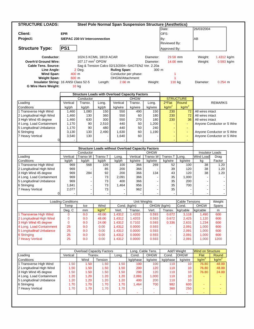
STRUCTURE LOADS: Steel Pole Normal Span Suspension Structure (Aesthetics)Date:
Client: EPR OFS:Project: SIEPAC 230 kV Interconnection By: AB
Reviewed By:
Structure Type: PS1 Approved By:
Conductor: 1024.5 KCMIL 18/19 ACAR Diameter: 29.59 mm Weight: 1.4312 kg/mOverh'd Ground Wire: 107.17 mm2 OPGW Diameter: 14.00 mm Weight: 0.593 kg/m
Cable Tens. Source: Sag & Tension Calcs 02/13/2004--SAGTEN2 Ver. 2.20aLine Angle: 2 Deg. Ruling Span: 300 mWind Span: 400 m Conductor per phase: 1
Weight Span: 600 m OHGW/Attachment: 1Insulator String: 16 ANSI Class 52-5 Length: 2.60 m Weight: 110 kg Diameter: 0.254 m
G Wire Hwre Weight: 10 kg
Structure Loads with Overload Capacity FactorsConductor OHGW
Loading Vertical Transv. Long. Vertical Transv. Long. 2*Flat RoundConditions kg/ph kg/ph kg/ph kg/wire kg/wire kg/wire kg/m2 kg/m2
1 Transverse High Wind 1,460 1,080 150 550 490 150 230 72 All wires intact2 Longitudinal High Wind 1,460 130 360 550 60 180 230 72 All wires intact3 High Wind 45 degree 1,460 630 300 550 270 180 230 36 All wires intact4 Long. Load Containment 1,170 90 2,510 440 50 1,200 - - Anyone Conductor or S Wire5 Longitudinal Unbalance 1,170 90 480 440 50 240 - - 6 Stringing 3,130 130 2,490 1,630 60 1,190 - - Anyone Conductor or S Wire7 Heavy Vertical 3,540 130 - 1,640 60 - - - Anyone Conductor or S Wire
0 - - - - - - - -
Structure Loads without Overload Capacity FactorsConductor OHGW
Loading Vertical Transv.W Transv.T Long. Vertical Transv.W Transv.T Long. Wind Load DragConditions kg/ph kg/ph kg/ph kg/ph kg/wire kg/wire kg/wire kg/wire kg Factor1 Transverse High Wind 969 568 109 100 366 269 52 100 38 1.202 Longitudinal High Wind 969 - 85 200 366 - 39 120 38 1.203 High Wind 45 degree 969 284 92 200 366 134 43 120 38 1.204 Long. Load Containment 969 - 73 2,091 366 - 35 1,000 - - 5 Longitudinal Unbalance 969 - 73 400 366 - 35 200 - - 6 Stringing 1,841 - 73 1,464 956 - 35 700 - - 7 Heavy Vertical 2,077 - 73 - 962 - 35 - - -
0 - - - - - - - - - -
Loading Conditions Unit Weights Cable Tensions WeightTemp Ice Wind Cond. (kg/m) OHGW (kg/m) Cond. OHGW Spans
Deg. C mm kg/m2 Vert. Transv. Vert. Transv. kg/cable kg/cable m1 Transverse High Wind 0 0.0 48.00 1.4312 1.4203 0.593 0.672 3,118 1,490 6002 Longitudinal High Wind 0 0.0 48.00 1.4312 1.4203 0.593 0.672 2,425 1,120 6003 High Wind 45 degree 0 0.0 24.00 1.4312 0.7102 0.593 0.336 2,631 1,234 6004 Long. Load Containment 25 0.0 0.00 1.4312 0.0000 0.593 - 2,091 1,000 6005 Longitudinal Unbalance 25 0.0 0.00 1.4312 0.0000 0.593 - 2,091 1,000 6006 Stringing 25 0.0 0.00 1.4312 0.0000 0.593 - 2,091 1,000 6007 Heavy Vertical 25 0.0 0.00 1.4312 0.0000 0.593 - 2,091 1,000 1200
Overload Capacity Factors Long. Cable Tens. Add'l Weight Wind on StructureLoading Vertical Transv. Long. Cond. OHGW Cond. OHGW Flat RoundConditions Wind Tension kg/phase kg/wire kg/phase kg/wire kg/m2 kg/m2
1 Transverse High Wind 1.50 1.50 1.50 1.50 100 100 110 10 76.80 48.00 2 Longitudinal High Wind 1.50 1.50 1.50 1.50 200 120 110 10 76.80 48.00 3 High Wind 45 degree 1.50 1.50 1.50 1.50 200 120 110 10 76.80 24.00 4 Long. Load Containment 1.20 1.20 1.20 1.20 2,091 1,000 110 10 - - 5 Longitudinal Unbalance 1.20 1.20 1.20 1.20 400 200 110 10 6 Stringing 1.70 1.70 1.70 1.70 1,464 700 982 600 - - 7 Heavy Vertical 1.70 1.70 1.70 1.70 - - 360 250 - -
- - - - -
26/03/2004
REMARKS
Insulator Loads
STRUCTURE

STRUCTURE LOADS: Steel Pole Medium Angle Deadend Structure (Aesthetics)Date:
Client: EPR OFS:Project: SIEPAC 230 kV Interconnection By: AB
Reviewed By:
Structure Type: PMS Approved By:
Conductor: 1024.5 KCMIL 18/19 ACAR Diameter: 29.59 mm Weight: 1.4312 kg/mOverh'd Ground Wire: 107.17 mm2 OPGW Diameter: 14.00 mm Weight: 0.593 kg/m
Cable Tens. Source: Sag & Tension Calcs 02/13/2004--SAGTEN2 Ver. 2.20aLine Angle: 30 Deg. Ruling Span: 300 mWind Span: 400 m Conductor per phase: 1
Weight Span: 1500 m OHGW/Attachment: 1Insulator String: 16 ANSI Class 52-5 Length: 2.60 m Weight: 110 kg Diameter: 0.254 m
G Wire Hwre Weight: 20 kg
Structure Loads with Overload Capacity FactorsConductor OHGW
Loading Vertical Transv. Long. Vertical Transv. Long. 2*Flat RoundConditions kg/ph kg/ph kg/ph kg/wire kg/wire kg/wire kg/m2 kg/m2
1 Transverse High Wind 3,720 3,340 750 1,370 1,570 380 230 72 All wires intact2 Longitudinal High Wind 3,720 1,890 360 1,370 870 180 230 72 All wires intact3 High Wind 45 degree 3,720 2,530 300 1,370 1,160 180 230 36 All wires intact4 Temporary deadend EDS 2,980 650 2,510 1,100 320 1,200 - - One or all wires, one side only5 Stringing 5,320 1,850 2,490 2,540 880 1,190 - - Anyone conductor or S. Wire6 Heavy Vertical 6,100 1,850 - 2,550 880 - - - Anyone conductor or S. Wire
0 - - - - - - - -
Structure Loads without Overload Capacity FactorsConductor OHGW
Loading Vertical Transv.W Transv.T Long. Vertical Transv.W Transv.T Long. Wind Load DragConditions kg/ph kg/ph kg/ph kg/ph kg/wire kg/wire kg/wire kg/wire kg Factor1 Transverse High Wind 2,477 568 1,614 500 910 269 771 250 38 1.202 Longitudinal High Wind 2,477 - 1,255 200 910 - 580 120 38 1.203 High Wind 45 degree 2,477 284 1,362 200 910 134 639 120 38 1.204 Temporary deadend EDS 2,477 - 541 2,091 910 - 259 1,000 - - 5 Stringing 3,129 - 1,082 1,464 1,490 - 518 700 - - 6 Heavy Vertical 3,586 - 1,082 2,091 1,495 - 518 1,000 - -
0 - - - - - - 518 - - 518
Loading Conditions Unit Weights Cable Tensions WeightTemp Ice Wind Cond. (kg/m) OHGW (kg/m) Cond. OHGW Spans
Deg. C mm kg/m2 Vert. Transv. Vert. Transv. kg/cable kg/cable m1 Transverse High Wind 0 0.0 48.00 1.4312 1.4203 0.593 0.672 3,118 1,490 15002 Longitudinal High Wind 0 0.0 48.00 1.4312 1.4203 0.593 0.672 2,425 1,120 15003 High Wind 45 degree 0 0.0 24.00 1.4312 0.7102 0.593 0.336 2,631 1,234 15004 Temporary deadend EDS 25 0.0 0.00 1.4312 0.0000 0.593 - 2,091 1,000 15005 Stringing 25 0.0 0.00 1.4312 0.0000 0.593 - 2,091 1,000 15006 Heavy Vertical 25 0.0 0.00 1.4312 0.0000 0.593 - 2,091 1,000 2100
1,000
Overload Capacity Factors Long. Cable Tens. Add'l Weight Wind on StructureLoading Vertical Transv. Long. Cond. OHGW Cond. OHGW Flat RoundConditions Wind Tension kg/phase kg/wire kg/phase kg/wire kg/m2 kg/m2
1 Transverse High Wind 1.50 1.50 1.50 1.50 500 250 110 20 76.80 48.00 2 Longitudinal High Wind 1.50 1.50 1.50 1.50 200 120 110 20 76.80 48.00 3 High Wind 45 degree 1.50 1.50 1.50 1.50 200 120 110 20 76.80 24.00 4 Temporary deadend EDS 1.20 1.20 1.20 1.20 2,091 1,000 110 20 - - 5 Stringing 1.70 1.70 1.70 1.70 1,464 700 982 600 - - 6 Heavy Vertical 1.70 1.70 1.70 1.70 2,091 1,000 580 250 - -
- 1,000 - - -
26/03/2004
REMARKS
Insulator Loads
STRUCTURE
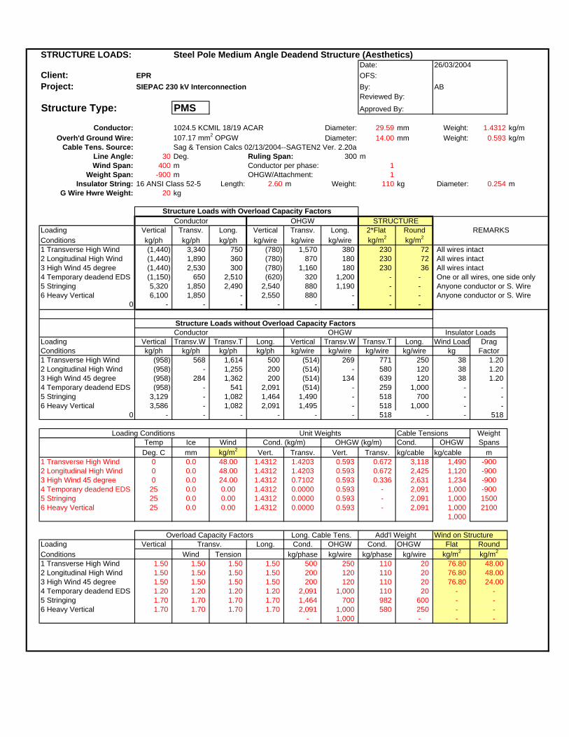
STRUCTURE LOADS: Steel Pole Medium Angle Deadend Structure (Aesthetics)Date:
Client: EPR OFS:Project: SIEPAC 230 kV Interconnection By: AB
Reviewed By:
Structure Type: PMS Approved By:
Conductor: 1024.5 KCMIL 18/19 ACAR Diameter: 29.59 mm Weight: 1.4312 kg/mOverh'd Ground Wire: 107.17 mm2 OPGW Diameter: 14.00 mm Weight: 0.593 kg/m
Cable Tens. Source: Sag & Tension Calcs 02/13/2004--SAGTEN2 Ver. 2.20aLine Angle: 30 Deg. Ruling Span: 300 mWind Span: 400 m Conductor per phase: 1
Weight Span: -900 m OHGW/Attachment: 1Insulator String: 16 ANSI Class 52-5 Length: 2.60 m Weight: 110 kg Diameter: 0.254 m
G Wire Hwre Weight: 20 kg
Structure Loads with Overload Capacity FactorsConductor OHGW
Loading Vertical Transv. Long. Vertical Transv. Long. 2*Flat RoundConditions kg/ph kg/ph kg/ph kg/wire kg/wire kg/wire kg/m2 kg/m2
1 Transverse High Wind (1,440) 3,340 750 (780) 1,570 380 230 72 All wires intact2 Longitudinal High Wind (1,440) 1,890 360 (780) 870 180 230 72 All wires intact3 High Wind 45 degree (1,440) 2,530 300 (780) 1,160 180 230 36 All wires intact4 Temporary deadend EDS (1,150) 650 2,510 (620) 320 1,200 - - One or all wires, one side only5 Stringing 5,320 1,850 2,490 2,540 880 1,190 - - Anyone conductor or S. Wire6 Heavy Vertical 6,100 1,850 - 2,550 880 - - - Anyone conductor or S. Wire
0 - - - - - - - -
Structure Loads without Overload Capacity FactorsConductor OHGW
Loading Vertical Transv.W Transv.T Long. Vertical Transv.W Transv.T Long. Wind Load DragConditions kg/ph kg/ph kg/ph kg/ph kg/wire kg/wire kg/wire kg/wire kg Factor1 Transverse High Wind (958) 568 1,614 500 (514) 269 771 250 38 1.202 Longitudinal High Wind (958) - 1,255 200 (514) - 580 120 38 1.203 High Wind 45 degree (958) 284 1,362 200 (514) 134 639 120 38 1.204 Temporary deadend EDS (958) - 541 2,091 (514) - 259 1,000 - - 5 Stringing 3,129 - 1,082 1,464 1,490 - 518 700 - - 6 Heavy Vertical 3,586 - 1,082 2,091 1,495 - 518 1,000 - -
0 - - - - - - 518 - - 518
Loading Conditions Unit Weights Cable Tensions WeightTemp Ice Wind Cond. (kg/m) OHGW (kg/m) Cond. OHGW Spans
Deg. C mm kg/m2 Vert. Transv. Vert. Transv. kg/cable kg/cable m1 Transverse High Wind 0 0.0 48.00 1.4312 1.4203 0.593 0.672 3,118 1,490 -9002 Longitudinal High Wind 0 0.0 48.00 1.4312 1.4203 0.593 0.672 2,425 1,120 -9003 High Wind 45 degree 0 0.0 24.00 1.4312 0.7102 0.593 0.336 2,631 1,234 -9004 Temporary deadend EDS 25 0.0 0.00 1.4312 0.0000 0.593 - 2,091 1,000 -9005 Stringing 25 0.0 0.00 1.4312 0.0000 0.593 - 2,091 1,000 15006 Heavy Vertical 25 0.0 0.00 1.4312 0.0000 0.593 - 2,091 1,000 2100
1,000
Overload Capacity Factors Long. Cable Tens. Add'l Weight Wind on StructureLoading Vertical Transv. Long. Cond. OHGW Cond. OHGW Flat RoundConditions Wind Tension kg/phase kg/wire kg/phase kg/wire kg/m2 kg/m2
1 Transverse High Wind 1.50 1.50 1.50 1.50 500 250 110 20 76.80 48.00 2 Longitudinal High Wind 1.50 1.50 1.50 1.50 200 120 110 20 76.80 48.00 3 High Wind 45 degree 1.50 1.50 1.50 1.50 200 120 110 20 76.80 24.00 4 Temporary deadend EDS 1.20 1.20 1.20 1.20 2,091 1,000 110 20 - - 5 Stringing 1.70 1.70 1.70 1.70 1,464 700 982 600 - - 6 Heavy Vertical 1.70 1.70 1.70 1.70 2,091 1,000 580 250 - -
- 1,000 - - -
26/03/2004
REMARKS
Insulator Loads
STRUCTURE

STRUCTURE LOADS: Steel Pole Normal Span Suspension Structure (Aesthetics)Date:
Client: EPR OFS:Project: SIEPAC 230 kV Interconnection By: AB
Reviewed By:
Structure Type: PD1 Approved By:
Conductor: 1024.5 KCMIL 18/19 ACAR Diameter: 29.59 mm Weight: 1.4312 kg/mOverh'd Ground Wire: 107.17 mm2 OPGW Diameter: 14.00 mm Weight: 0.593 kg/m
Cable Tens. Source: Sag & Tension Calcs 02/13/2004--SAGTEN2 Ver. 2.20aLine Angle: 2 Deg. Ruling Span: 300 mWind Span: 400 m Conductor per phase: 1
Weight Span: 600 m OHGW/Attachment: 1Insulator String: 16 ANSI Class 52-5 Length: 2.60 m Weight: 110 kg Diameter: 0.254 m
G Wire Hwre Weight: 10 kg
Structure Loads with Overload Capacity FactorsConductor OHGW
Loading Vertical Transv. Long. Vertical Transv. Long. 2*Flat RoundConditions kg/ph kg/ph kg/ph kg/wire kg/wire kg/wire kg/m2 kg/m2
1 Transverse High Wind 1,460 1,080 150 550 490 150 230 72 All wires intact2 Longitudinal High Wind 1,460 130 360 550 60 180 230 72 All wires intact3 High Wind 45 degree 1,460 630 300 550 270 180 230 36 All wires intact4 Long. Load Containment 1,170 90 2,510 440 50 1,200 - - Anyone Conductor or S Wire5 Stringing 3,130 130 2,490 1,630 60 1,190 - - Anyone Conductor or S Wire6 Heavy Vertical 3,540 130 - 1,640 60 - - - Anyone Conductor or S Wire
0 - - - - - - - -
Structure Loads without Overload Capacity FactorsConductor OHGW
Loading Vertical Transv.W Transv.T Long. Vertical Transv.W Transv.T Long. Wind Load DragConditions kg/ph kg/ph kg/ph kg/ph kg/wire kg/wire kg/wire kg/wire kg Factor1 Transverse High Wind 969 568 109 100 366 269 52 100 38 1.202 Longitudinal High Wind 969 - 85 200 366 - 39 120 38 1.203 High Wind 45 degree 969 284 92 200 366 134 43 120 38 1.204 Long. Load Containment 969 - 73 2,091 366 - 35 1,000 - - 5 Stringing 1,841 - 73 1,464 956 - 35 700 - - 6 Heavy Vertical 2,077 - 73 - 962 - 35 - - -
0 - - - - - - - - - -
Loading Conditions Unit Weights Cable Tensions WeightTemp Ice Wind Cond. (kg/m) OHGW (kg/m) Cond. OHGW Spans
Deg. C mm kg/m2 Vert. Transv. Vert. Transv. kg/cable kg/cable m1 Transverse High Wind 0 0.0 48.00 1.4312 1.4203 0.593 0.672 3,118 1,490 6002 Longitudinal High Wind 0 0.0 48.00 1.4312 1.4203 0.593 0.672 2,425 1,120 6003 High Wind 45 degree 0 0.0 24.00 1.4312 0.7102 0.593 0.336 2,631 1,234 6004 Long. Load Containment 25 0.0 0.00 1.4312 0.0000 0.593 - 2,091 1,000 6005 Stringing 25 0.0 0.00 1.4312 0.0000 0.593 - 2,091 1,000 6006 Heavy Vertical 25 0.0 0.00 1.4312 0.0000 0.593 - 2,091 1,000 1200
Overload Capacity Factors Long. Cable Tens. Add'l Weight Wind on StructureLoading Vertical Transv. Long. Cond. OHGW Cond. OHGW Flat RoundConditions Wind Tension kg/phase kg/wire kg/phase kg/wire kg/m2 kg/m2
1 Transverse High Wind 1.50 1.50 1.50 1.50 100 100 110 10 76.80 48.00 2 Longitudinal High Wind 1.50 1.50 1.50 1.50 200 120 110 10 76.80 48.00 3 High Wind 45 degree 1.50 1.50 1.50 1.50 200 120 110 10 76.80 24.00 4 Long. Load Containment 1.20 1.20 1.20 1.20 2,091 1,000 110 10 - - 5 Stringing 1.70 1.70 1.70 1.70 1,464 700 982 600 - - 6 Heavy Vertical 1.70 1.70 1.70 1.70 - - 360 250 - -
- - - - -
26/03/2004
REMARKS
Insulator Loads
STRUCTURE

STRUCTURE LOADS: Steel Pole Medium Angle Deadend Structure (Aesthetics)Date:
Client: EPR OFS:Project: SIEPAC 230 kV Interconnection By: AB
Reviewed By:
Structure Type: PMD Approved By:
Conductor: 1024.5 KCMIL 18/19 ACAR Diameter: 29.59 mm Weight: 1.4312 kg/mOverh'd Ground Wire: 107.17 mm2 OPGW Diameter: 14.00 mm Weight: 0.593 kg/m
Cable Tens. Source: Sag & Tension Calcs 02/13/2004--SAGTEN2 Ver. 2.20aLine Angle: 30 Deg. Ruling Span: 300 mWind Span: 400 m Conductor per phase: 1
Weight Span: 1500 m OHGW/Attachment: 1Insulator String: 16 ANSI Class 52-5 Length: 2.60 m Weight: 110 kg Diameter: 0.254 m
G Wire Hwre Weight: 20 kg
Structure Loads with Overload Capacity FactorsConductor OHGW
Loading Vertical Transv. Long. Vertical Transv. Long. 2*Flat RoundConditions kg/ph kg/ph kg/ph kg/wire kg/wire kg/wire kg/m2 kg/m2
1 Transverse High Wind 3,720 3,340 750 1,370 1,570 380 230 72 All wires intact2 Longitudinal High Wind 3,720 1,890 360 1,370 870 180 230 72 All wires intact3 High Wind 45 degree 3,720 2,530 300 1,370 1,160 180 230 36 All wires intact4 Temporary deadend EDS 2,980 650 2,510 1,100 320 1,200 - - One or all wires, one side only5 Stringing 5,320 1,850 2,490 2,540 880 1,190 - - Anyone conductor or S. Wire6 Heavy Vertical 6,100 1,850 - 2,550 880 - - - Anyone conductor or S. Wire
0 - - - - - - - -
Structure Loads without Overload Capacity FactorsConductor OHGW
Loading Vertical Transv.W Transv.T Long. Vertical Transv.W Transv.T Long. Wind Load DragConditions kg/ph kg/ph kg/ph kg/ph kg/wire kg/wire kg/wire kg/wire kg Factor1 Transverse High Wind 2,477 568 1,614 500 910 269 771 250 38 1.202 Longitudinal High Wind 2,477 - 1,255 200 910 - 580 120 38 1.203 High Wind 45 degree 2,477 284 1,362 200 910 134 639 120 38 1.204 Temporary deadend EDS 2,477 - 541 2,091 910 - 259 1,000 - - 5 Stringing 3,129 - 1,082 1,464 1,490 - 518 700 - - 6 Heavy Vertical 3,586 - 1,082 2,091 1,495 - 518 1,000 - -
0 - - - - - - 518 - - 518
Loading Conditions Unit Weights Cable Tensions WeightTemp Ice Wind Cond. (kg/m) OHGW (kg/m) Cond. OHGW Spans
Deg. C mm kg/m2 Vert. Transv. Vert. Transv. kg/cable kg/cable m1 Transverse High Wind 0 0.0 48.00 1.4312 1.4203 0.593 0.672 3,118 1,490 15002 Longitudinal High Wind 0 0.0 48.00 1.4312 1.4203 0.593 0.672 2,425 1,120 15003 High Wind 45 degree 0 0.0 24.00 1.4312 0.7102 0.593 0.336 2,631 1,234 15004 Temporary deadend EDS 25 0.0 0.00 1.4312 0.0000 0.593 - 2,091 1,000 15005 Stringing 25 0.0 0.00 1.4312 0.0000 0.593 - 2,091 1,000 15006 Heavy Vertical 25 0.0 0.00 1.4312 0.0000 0.593 - 2,091 1,000 2100
1,000
Overload Capacity Factors Long. Cable Tens. Add'l Weight Wind on StructureLoading Vertical Transv. Long. Cond. OHGW Cond. OHGW Flat RoundConditions Wind Tension kg/phase kg/wire kg/phase kg/wire kg/m2 kg/m2
1 Transverse High Wind 1.50 1.50 1.50 1.50 500 250 110 20 76.80 48.00 2 Longitudinal High Wind 1.50 1.50 1.50 1.50 200 120 110 20 76.80 48.00 3 High Wind 45 degree 1.50 1.50 1.50 1.50 200 120 110 20 76.80 24.00 4 Temporary deadend EDS 1.20 1.20 1.20 1.20 2,091 1,000 110 20 - - 5 Stringing 1.70 1.70 1.70 1.70 1,464 700 982 600 - - 6 Heavy Vertical 1.70 1.70 1.70 1.70 2,091 1,000 580 250 - -
- 1,000 - - -
26/03/2004
REMARKS
Insulator Loads
STRUCTURE

STRUCTURE LOADS: Steel Pole Medium Angle Deadend Structure (Aesthetics)Date:
Client: EPR OFS:Project: SIEPAC 230 kV Interconnection By: AB
Reviewed By:
Structure Type: PMD Approved By:
Conductor: 1024.5 KCMIL 18/19 ACAR Diameter: 29.59 mm Weight: 1.4312 kg/mOverh'd Ground Wire: 107.17 mm2 OPGW Diameter: 14.00 mm Weight: 0.593 kg/m
Cable Tens. Source: Sag & Tension Calcs 02/13/2004--SAGTEN2 Ver. 2.20aLine Angle: 30 Deg. Ruling Span: 300 mWind Span: 400 m Conductor per phase: 1
Weight Span: -900 m OHGW/Attachment: 1Insulator String: 16 ANSI Class 52-5 Length: 2.60 m Weight: 110 kg Diameter: 0.254 m
G Wire Hwre Weight: 20 kg
Structure Loads with Overload Capacity FactorsConductor OHGW
Loading Vertical Transv. Long. Vertical Transv. Long. 2*Flat RoundConditions kg/ph kg/ph kg/ph kg/wire kg/wire kg/wire kg/m2 kg/m2
1 Transverse High Wind (1,440) 3,340 750 (780) 1,570 380 230 72 All wires intact2 Longitudinal High Wind (1,440) 1,890 360 (780) 870 180 230 72 All wires intact3 High Wind 45 degree (1,440) 2,530 300 (780) 1,160 180 230 36 All wires intact4 Temporary deadend EDS (1,150) 650 2,510 (620) 320 1,200 - - One or all wires, one side only5 Stringing (530) 1,850 2,490 120 880 1,190 - - Anyone conductor or S. Wire6 Heavy Vertical 6,100 1,850 - 2,550 880 - - - Anyone conductor or S. Wire
0 - - - - - - - -
Structure Loads without Overload Capacity FactorsConductor OHGW
Loading Vertical Transv.W Transv.T Long. Vertical Transv.W Transv.T Long. Wind Load DragConditions kg/ph kg/ph kg/ph kg/ph kg/wire kg/wire kg/wire kg/wire kg Factor1 Transverse High Wind (958) 568 1,614 500 (514) 269 771 250 38 1.202 Longitudinal High Wind (958) - 1,255 200 (514) - 580 120 38 1.203 High Wind 45 degree (958) 284 1,362 200 (514) 134 639 120 38 1.204 Temporary deadend EDS (958) - 541 2,091 (514) - 259 1,000 - - 5 Stringing (306) - 1,082 1,464 66 - 518 700 - - 6 Heavy Vertical 3,586 - 1,082 2,091 1,495 - 518 1,000 - -
0 - - - - - - 518 - - 518
Loading Conditions Unit Weights Cable Tensions WeightTemp Ice Wind Cond. (kg/m) OHGW (kg/m) Cond. OHGW Spans
Deg. C mm kg/m2 Vert. Transv. Vert. Transv. kg/cable kg/cable m1 Transverse High Wind 0 0.0 48.00 1.4312 1.4203 0.593 0.672 3,118 1,490 -9002 Longitudinal High Wind 0 0.0 48.00 1.4312 1.4203 0.593 0.672 2,425 1,120 -9003 High Wind 45 degree 0 0.0 24.00 1.4312 0.7102 0.593 0.336 2,631 1,234 -9004 Temporary deadend EDS 25 0.0 0.00 1.4312 0.0000 0.593 - 2,091 1,000 -9005 Stringing 25 0.0 0.00 1.4312 0.0000 0.593 - 2,091 1,000 -9006 Heavy Vertical 25 0.0 0.00 1.4312 0.0000 0.593 - 2,091 1,000 2100
1,000
Overload Capacity Factors Long. Cable Tens. Add'l Weight Wind on StructureLoading Vertical Transv. Long. Cond. OHGW Cond. OHGW Flat RoundConditions Wind Tension kg/phase kg/wire kg/phase kg/wire kg/m2 kg/m2
1 Transverse High Wind 1.50 1.50 1.50 1.50 500 250 110 20 76.80 48.00 2 Longitudinal High Wind 1.50 1.50 1.50 1.50 200 120 110 20 76.80 48.00 3 High Wind 45 degree 1.50 1.50 1.50 1.50 200 120 110 20 76.80 24.00 4 Temporary deadend EDS 1.20 1.20 1.20 1.20 2,091 1,000 110 20 - - 5 Stringing 1.70 1.70 1.70 1.70 1,464 700 982 600 - - 6 Heavy Vertical 1.70 1.70 1.70 1.70 2,091 1,000 580 250 - -
- 1,000 - - -
26/03/2004
REMARKS
Insulator Loads
STRUCTURE
ANEXO 28A
Hojas de Cálculo de las Estructuras de 4 Circuitos (2TD1, 2TMD, 2TDD)
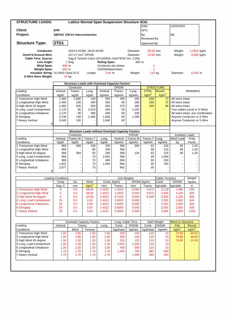
STRUCTURE LOADS: Lattice Normal Span Suspension Structure 4CktDate:
Client: EPR OFS:Project: SIEPAC 230 kV Interconnection By: AB
Reviewed By:
Structure Type: 2TD1 Approved By:
Conductor: 1024.5 KCMIL 18/19 ACAR Diameter: 29.59 mm Weight: 1.4312 kg/mOverh'd Ground Wire: 107.17 mm2 OPGW Diameter: 14.00 mm Weight: 0.593 kg/m
Cable Tens. Source: Sag & Tension Calcs 02/13/2004--SAGTEN2 Ver. 2.20aLine Angle: 2 Deg. Ruling Span: 300 mWind Span: 400 m Conductor per phase: 1
Weight Span: 600 m OHGW/Attachment: 1Insulator String: 16 ANSI Class 52-5 Length: 2.60 m Weight: 110 kg Diameter: 0.254 m
G Wire Hwre Weight: 10 kg
Structure Loads with Overload Capacity FactorsConductor OHGW
Loading Vertical Transv. Long. Vertical Transv. Long. 2*Flat RoundConditions kg/ph kg/ph kg/ph kg/wire kg/wire kg/wire kg/m2 kg/m2
1 Transverse High Wind 1,460 1,080 150 550 490 150 230 72 All wires intact2 Longitudinal High Wind 1,460 130 360 550 60 180 230 72 All wires intact3 High Wind 45 degree 1,460 630 300 550 270 180 230 36 All wires intact4 Long. Load Containment 1,170 90 2,510 440 50 1,200 - - Two cables (cond or S Wire)5 Longitudinal Unbalance 1,170 90 480 440 50 240 - - All wires intact, any combination6 Stringing 3,130 130 2,490 1,630 60 1,190 - - Anyone Conductor or S Wire7 Heavy Vertical 3,540 130 - 1,640 60 - - - Anyone Conductor or S Wire
0 - - - - - - - -
Structure Loads without Overload Capacity FactorsConductor OHGW
Loading Vertical Transv.W Transv.T Long. Vertical Transv.W Transv.T Long. Wind Load DragConditions kg/ph kg/ph kg/ph kg/ph kg/wire kg/wire kg/wire kg/wire kg Factor1 Transverse High Wind 969 568 109 100 366 269 52 100 38 1.202 Longitudinal High Wind 969 - 85 200 366 - 39 120 38 1.203 High Wind 45 degree 969 284 92 200 366 134 43 120 38 1.204 Long. Load Containment 969 - 73 2,091 366 - 35 1,000 - - 5 Longitudinal Unbalance 969 - 73 400 366 - 35 200 - - 6 Stringing 1,841 - 73 1,464 956 - 35 700 - - 7 Heavy Vertical 2,077 - 73 - 962 - 35 - - -
0 - - - - - - - - - -
Loading Conditions Unit Weights Cable Tensions WeightTemp Ice Wind Cond. (kg/m) OHGW (kg/m) Cond. OHGW SpansDeg. C mm kg/m2 Vert. Transv. Vert. Transv. kg/cable kg/cable m
1 Transverse High Wind 0 0.0 48.00 1.4312 1.4203 0.593 0.672 3,118 1,490 6002 Longitudinal High Wind 0 0.0 48.00 1.4312 1.4203 0.593 0.672 2,425 1,120 6003 High Wind 45 degree 0 0.0 24.00 1.4312 0.7102 0.593 0.336 2,631 1,234 6004 Long. Load Containment 25 0.0 0.00 1.4312 0.0000 0.593 - 2,091 1,000 6005 Longitudinal Unbalance 25 0.0 0.00 1.4312 0.0000 0.593 - 2,091 1,000 6006 Stringing 25 0.0 0.00 1.4312 0.0000 0.593 - 2,091 1,000 6007 Heavy Vertical 25 0.0 0.00 1.4312 0.0000 0.593 - 2,091 1,000 1200
Overload Capacity Factors Long. Cable Tens. Add'l Weight Wind on StructureLoading Vertical Transv. Long. Cond. OHGW Cond. OHGW Flat RoundConditions Wind Tension kg/phase kg/wire kg/phase kg/wire kg/m2 kg/m2
1 Transverse High Wind 1.50 1.50 1.50 1.50 100 100 110 10 76.80 48.00 2 Longitudinal High Wind 1.50 1.50 1.50 1.50 200 120 110 10 76.80 48.00 3 High Wind 45 degree 1.50 1.50 1.50 1.50 200 120 110 10 76.80 24.00 4 Long. Load Containment 1.20 1.20 1.20 1.20 2,091 1,000 110 10 - - 5 Longitudinal Unbalance 1.20 1.20 1.20 1.20 400 200 110 10 6 Stringing 1.70 1.70 1.70 1.70 1,464 700 982 600 - - 7 Heavy Vertical 1.70 1.70 1.70 1.70 - 1,000 360 250 - -
- - - - -
12/03/2004
REMARKS
Insulator Loads
STRUCTURE

STRUCTURE LOADS: Lattice Medium Angle Deadend Structure 4CktDate:
Client: EPR OFS:Project: SIEPAC 230 kV Interconnection By: AB
Reviewed By:
Structure Type: 2TMD Approved By:
Conductor: 1024.5 KCMIL 18/19 ACAR Diameter: 29.59 mm Weight: 1.4312 kg/mOverh'd Ground Wire: 107.17 mm2 OPGW Diameter: 14.00 mm Weight: 0.593 kg/m
Cable Tens. Source: Sag & Tension Calcs 02/13/2004--SAGTEN2 Ver. 2.20aLine Angle: 30 Deg. Ruling Span: 300 mWind Span: 400 m Conductor per phase: 1
Weight Span: 600 m OHGW/Attachment: 1Insulator String: 16 ANSI Class 52-5 Length: 2.60 m Weight: 110 kg Diameter: 0.254 m
G Wire Hwre Weight: 20 kg
Structure Loads with Overload Capacity FactorsConductor OHGW
Loading Vertical Transv. Long. Vertical Transv. Long. 2*Flat RoundConditions kg/ph kg/ph kg/ph kg/wire kg/wire kg/wire kg/m2 kg/m2
1 Transverse High Wind 1,790 3,340 750 570 1,570 380 230 72 All wires intact2 Longitudinal High Wind 1,790 1,890 360 570 870 180 230 72 All wires intact3 High Wind 45 degree 1,790 2,530 300 570 1,160 180 230 36 All wires intact4 Temporary deadend EDS 1,430 650 2,510 460 320 1,200 - - One or all wires, one side only5 Stringing 3,130 1,850 2,490 1,630 880 1,190 - - Anyone conductor or S. Wire6 Heavy Vertical 3,910 1,850 - 1,640 880 - - - Anyone conductor or S. Wire
0 - - - - - - - -
Structure Loads without Overload Capacity FactorsConductor OHGW
Loading Vertical Transv.W Transv.T Long. Vertical Transv.W Transv.T Long. Wind Load DragConditions kg/ph kg/ph kg/ph kg/ph kg/wire kg/wire kg/wire kg/wire kg Factor1 Transverse High Wind 1,189 568 1,614 500 376 269 771 250 38 1.202 Longitudinal High Wind 1,189 - 1,255 200 376 - 580 120 38 1.203 High Wind 45 degree 1,189 284 1,362 200 376 134 639 120 38 1.204 Temporary deadend EDS 1,189 - 541 2,091 376 - 259 1,000 - - 5 Stringing 1,841 - 1,082 1,464 956 - 518 700 - - 6 Heavy Vertical 2,297 - 1,082 2,091 962 - 518 1,000 - -
0 - - - - - - 518 - - 518
Loading Conditions Unit Weights Cable Tensions WeightTemp Ice Wind Cond. (kg/m) OHGW (kg/m) Cond. OHGW SpansDeg. C mm kg/m2 Vert. Transv. Vert. Transv. kg/cable kg/cable m
1 Transverse High Wind 0 0.0 48.00 1.4312 1.4203 0.593 0.672 3,118 1,490 6002 Longitudinal High Wind 0 0.0 48.00 1.4312 1.4203 0.593 0.672 2,425 1,120 6003 High Wind 45 degree 0 0.0 24.00 1.4312 0.7102 0.593 0.336 2,631 1,234 6004 Temporary deadend EDS 25 0.0 0.00 1.4312 0.0000 0.593 - 2,091 1,000 6005 Stringing 25 0.0 0.00 1.4312 0.0000 0.593 - 2,091 1,000 6006 Heavy Vertical 25 0.0 0.00 1.4312 0.0000 0.593 - 2,091 1,000 1200
1,000
Overload Capacity Factors Long. Cable Tens. Add'l Weight Wind on StructureLoading Vertical Transv. Long. Cond. OHGW Cond. OHGW Flat RoundConditions Wind Tension kg/phase kg/wire kg/phase kg/wire kg/m2 kg/m2
1 Transverse High Wind 1.50 1.50 1.50 1.50 500 250 110 20 76.80 48.00 2 Longitudinal High Wind 1.50 1.50 1.50 1.50 200 120 110 20 76.80 48.00 3 High Wind 45 degree 1.50 1.50 1.50 1.50 200 120 110 20 76.80 24.00 4 Temporary deadend EDS 1.20 1.20 1.20 1.20 2,091 1,000 110 20 - - 5 Stringing 1.70 1.70 1.70 1.70 1,464 700 982 600 - - 6 Heavy Vertical 1.70 1.70 1.70 1.70 2,091 1,000 580 250 - -
- 1,000 - - -
12/03/2004
REMARKS
Insulator Loads
STRUCTURE
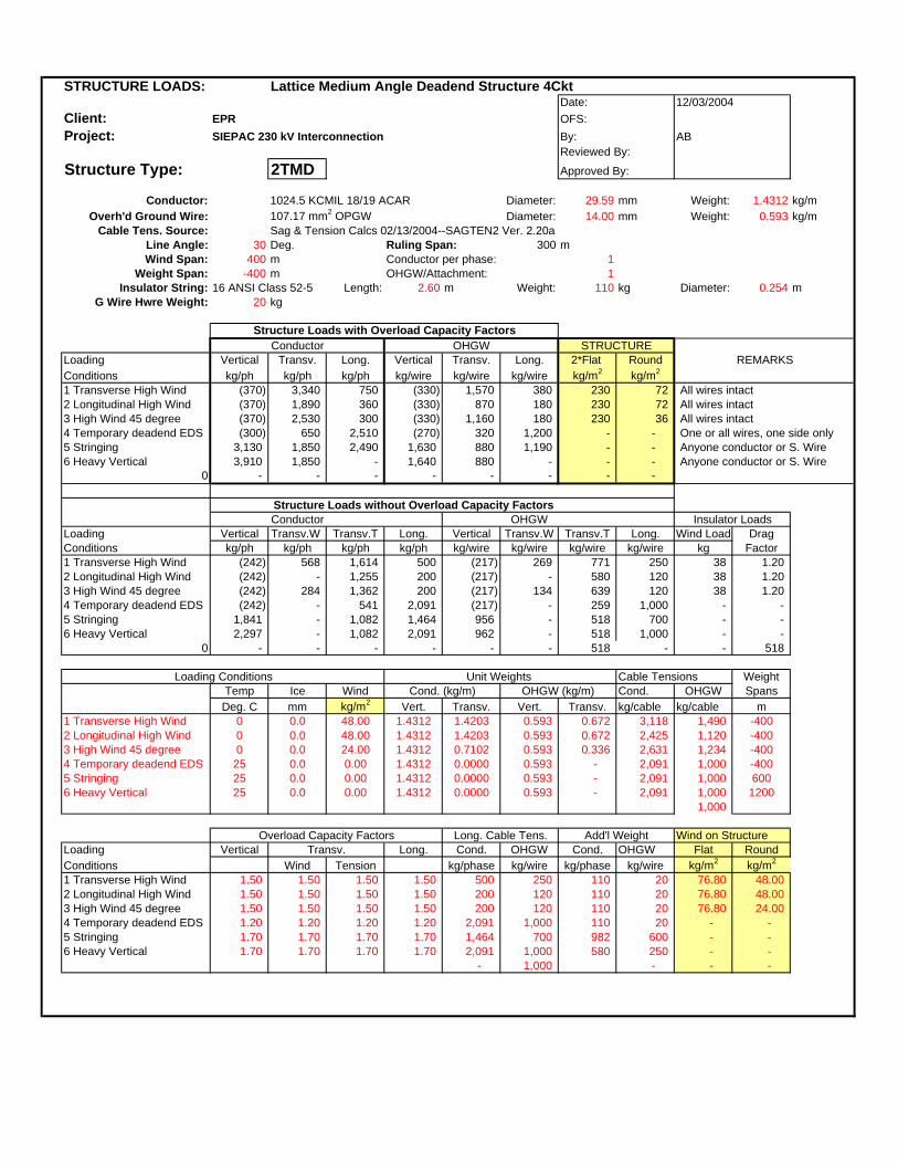
STRUCTURE LOADS: Lattice Medium Angle Deadend Structure 4CktDate:
Client: EPR OFS:Project: SIEPAC 230 kV Interconnection By: AB
Reviewed By:
Structure Type: 2TMD Approved By:
Conductor: 1024.5 KCMIL 18/19 ACAR Diameter: 29.59 mm Weight: 1.4312 kg/mOverh'd Ground Wire: 107.17 mm2 OPGW Diameter: 14.00 mm Weight: 0.593 kg/m
Cable Tens. Source: Sag & Tension Calcs 02/13/2004--SAGTEN2 Ver. 2.20aLine Angle: 30 Deg. Ruling Span: 300 mWind Span: 400 m Conductor per phase: 1
Weight Span: -400 m OHGW/Attachment: 1Insulator String: 16 ANSI Class 52-5 Length: 2.60 m Weight: 110 kg Diameter: 0.254 m
G Wire Hwre Weight: 20 kg
Structure Loads with Overload Capacity FactorsConductor OHGW
Loading Vertical Transv. Long. Vertical Transv. Long. 2*Flat RoundConditions kg/ph kg/ph kg/ph kg/wire kg/wire kg/wire kg/m2 kg/m2
1 Transverse High Wind (370) 3,340 750 (330) 1,570 380 230 72 All wires intact2 Longitudinal High Wind (370) 1,890 360 (330) 870 180 230 72 All wires intact3 High Wind 45 degree (370) 2,530 300 (330) 1,160 180 230 36 All wires intact4 Temporary deadend EDS (300) 650 2,510 (270) 320 1,200 - - One or all wires, one side only5 Stringing 3,130 1,850 2,490 1,630 880 1,190 - - Anyone conductor or S. Wire6 Heavy Vertical 3,910 1,850 - 1,640 880 - - - Anyone conductor or S. Wire
0 - - - - - - - -
Structure Loads without Overload Capacity FactorsConductor OHGW
Loading Vertical Transv.W Transv.T Long. Vertical Transv.W Transv.T Long. Wind Load DragConditions kg/ph kg/ph kg/ph kg/ph kg/wire kg/wire kg/wire kg/wire kg Factor1 Transverse High Wind (242) 568 1,614 500 (217) 269 771 250 38 1.202 Longitudinal High Wind (242) - 1,255 200 (217) - 580 120 38 1.203 High Wind 45 degree (242) 284 1,362 200 (217) 134 639 120 38 1.204 Temporary deadend EDS (242) - 541 2,091 (217) - 259 1,000 - - 5 Stringing 1,841 - 1,082 1,464 956 - 518 700 - - 6 Heavy Vertical 2,297 - 1,082 2,091 962 - 518 1,000 - -
0 - - - - - - 518 - - 518
Loading Conditions Unit Weights Cable Tensions WeightTemp Ice Wind Cond. (kg/m) OHGW (kg/m) Cond. OHGW SpansDeg. C mm kg/m2 Vert. Transv. Vert. Transv. kg/cable kg/cable m
1 Transverse High Wind 0 0.0 48.00 1.4312 1.4203 0.593 0.672 3,118 1,490 -4002 Longitudinal High Wind 0 0.0 48.00 1.4312 1.4203 0.593 0.672 2,425 1,120 -4003 High Wind 45 degree 0 0.0 24.00 1.4312 0.7102 0.593 0.336 2,631 1,234 -4004 Temporary deadend EDS 25 0.0 0.00 1.4312 0.0000 0.593 - 2,091 1,000 -4005 Stringing 25 0.0 0.00 1.4312 0.0000 0.593 - 2,091 1,000 6006 Heavy Vertical 25 0.0 0.00 1.4312 0.0000 0.593 - 2,091 1,000 1200
1,000
Overload Capacity Factors Long. Cable Tens. Add'l Weight Wind on StructureLoading Vertical Transv. Long. Cond. OHGW Cond. OHGW Flat RoundConditions Wind Tension kg/phase kg/wire kg/phase kg/wire kg/m2 kg/m2
1 Transverse High Wind 1.50 1.50 1.50 1.50 500 250 110 20 76.80 48.00 2 Longitudinal High Wind 1.50 1.50 1.50 1.50 200 120 110 20 76.80 48.00 3 High Wind 45 degree 1.50 1.50 1.50 1.50 200 120 110 20 76.80 24.00 4 Temporary deadend EDS 1.20 1.20 1.20 1.20 2,091 1,000 110 20 - - 5 Stringing 1.70 1.70 1.70 1.70 1,464 700 982 600 - - 6 Heavy Vertical 1.70 1.70 1.70 1.70 2,091 1,000 580 250 - -
- 1,000 - - -
12/03/2004
REMARKS
Insulator Loads
STRUCTURE
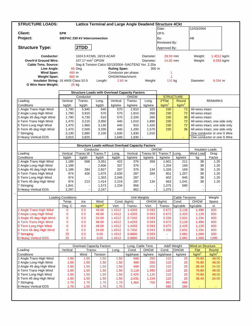
STRUCTURE LOADS: Lattice Terminal and Large Angle Deadend Structure 4CktDate:
Client: EPR OFS:Project: SIEPAC 230 kV Interconnection By: AB
Reviewed By:
Structure Type: 2TDD Approved By:
Conductor: 1024.5 KCMIL 18/19 ACAR Diameter: 29.59 mm Weight: 1.4312 kg/mOverh'd Ground Wire: 107.17 mm2 OPGW Diameter: 14.00 mm Weight: 0.593 kg/m
Cable Tens. Source: Sag & Tension Calcs 02/13/2004--SAGTEN2 Ver. 2.20aLine Angle: 65 Deg. Ruling Span: 300 mWind Span: 400 m Conductor per phase: 1
Weight Span: 600 m OHGW/Attachment: 1Insulator String: 16 ANSI Class 52-5 Length: 2.60 m Weight: 110 kg Diameter: 0.254 m
G Wire Hwre Weight: 20 kg
Structure Loads with Overload Capacity FactorsConductor OHGW
Loading Vertical Transv. Long. Vertical Transv. Long. 2*Flat RoundConditions kg/ph kg/ph kg/ph kg/wire kg/wire kg/wire kg/m2 kg/m2
1 Angle Trans High Wind 1,790 5,940 640 570 2,810 320 230 72 All wires intact2 Angle Long High Wind 1,790 3,910 570 570 1,810 260 230 72 All wires intact3 Angle 45 deg High Wind 1,790 4,730 510 570 2,200 260 230 36 All wires intact4 Term Trans High Wind 1,470 3,210 3,950 440 1,610 1,890 230 72 All wires intact, one side only5 Term Long High Wind 1,470 1,960 3,130 440 910 1,420 230 72 All wires intact, one side only6 Term 45 deg High Wind 1,470 2,500 3,330 440 1,200 1,570 230 36 All wires intact, one side only7 Stringing 3,130 2,680 2,100 1,630 1,830 1,010 One conductor or one S Wire8 Heavy Vertical EDS 3,910 3,820 - 1,640 1,830 - - - One conductor or one S Wire
Structure Loads without Overload Capacity Factors
Loading Vertical Transv.W Transv.T Long. Vertical Transv.W Transv.T Long. Wind Load DragConditions kg/ph kg/ph kg/ph kg/ph kg/wire kg/wire kg/wire kg/wire kg Factor1 Angle Trans High Wind 1,189 568 3,351 422 376 269 1,601 211 38 1.202 Angle Long High Wind 1,189 - 2,606 337 376 - 1,204 169 38 1.203 Angle 45 deg High Wind 1,189 284 2,827 337 376 134 1,326 169 38 1.20 4 Term Trans High Wind 974 426 1,675 2,630 287 269 801 1,257 38 1.20 5 Term Long High Wind 974 - 1,303 2,045 287 - 602 945 38 1.20 6 Term 45 deg High Wind 974 213 1,414 2,219 287 134 663 1,041 38 1.20 7 Stringing 1,841 - 1,573 1,234 956 - 1,075 590 - -8 Heavy Vertical EDS 2,297 - 2,247 - 962 - 1,075 - - -
- Loading Conditions Unit Weights Cable Tensions Weight
Temp Ice Wind Cond. (kg/m) OHGW (kg/m) Cond. OHGW SpansDeg. C mm kg/m2 Vert. Transv. Vert. Transv. kg/cable kg/cable m
1 Angle Trans High Wind 0 0.0 48.00 1.4312 1.4203 0.593 0.672 3,118 1,490 6002 Angle Long High Wind 0 0.0 48.00 1.4312 1.4203 0.593 0.672 2,425 1,120 6003 Angle 45 deg High Wind 0 0.0 24.00 1.4312 0.7102 0.593 0.336 2,631 1,234 6004 Term Trans High Wind 0 0.0 48.00 1.4312 1.4203 0.593 0.672 3,118 1,490 6005 Term Long High Wind 0 0.0 48.00 1.4312 1.4203 0.593 0.672 2,425 1,120 6006 Term 45 deg High Wind 0 0.0 24.00 1.4312 0.7102 0.593 0.336 2,631 1,234 6007 Stringing 25 0.0 0.00 1.4312 0.0000 0.593 - 2,091 1,000 6008 Heavy Vertical EDS 25 0.0 0.00 1.4312 0.0000 0.593 - 2,091 1,000 1200
Overload Capacity Factors Long. Cable Tens. Add'l Weight Wind on StructureLoading Vertical Transv. Long. Cond. OHGW Cond. OHGW Flat RoundConditions Wind Tension kg/phase kg/wire kg/phase kg/wire kg/m2 kg/m2
1 Angle Trans High Wind 1.50 1.50 1.50 1.50 500 250 110 20 76.80 48.00 2 Angle Long High Wind 1.50 1.50 1.50 1.50 400 200 110 20 76.80 48.00 3 Angle 45 deg High Wind 1.50 1.50 1.50 1.50 400 200 110 20 38.40 24.00 4 Term Trans High Wind 1.50 1.50 1.50 1.50 3,118 1,490 110 20 76.80 48.00 5 Term Long High Wind 1.50 1.50 1.50 1.50 2,425 1,120 110 20 76.80 48.00 6 Term 45 deg High Wind 1.50 1.50 1.50 1.50 2,631 1,234 110 20 38.40 24.00 7 Stringing 1.70 1.70 1.70 1.70 1,464 700 982 600 8 Heavy Vertical EDS 1.70 1.00 1.70 1.70 - - 580 250 - -
Conductor OHGW
12/03/2004
REMARKS
Insulator Loads
STRUCTURE

STRUCTURE LOADS: Lattice Terminal and Large Angle Deadend Structure 4CktDate:
Client: EPR OFS:Project: SIEPAC 230 kV Interconnection By: AB
Reviewed By:
Structure Type: 2TDD Approved By:
Conductor: 1024.5 KCMIL 18/19 ACAR Diameter: 29.59 mm Weight: 1.4312 kg/mOverh'd Ground Wire: 107.17 mm2 OPGW Diameter: 14.00 mm Weight: 0.593 kg/m
Cable Tens. Source: Sag & Tension Calcs 02/13/2004--SAGTEN2 Ver. 2.20aLine Angle: 65 Deg. Ruling Span: 300 mWind Span: 400 m Conductor per phase: 1
Weight Span: -400 m OHGW/Attachment: 1Insulator String: 16 ANSI Class 52-5 Length: 2.60 m Weight: 110 kg Diameter: 0.254 m
G Wire Hwre Weight: 20 kg
Structure Loads with Overload Capacity FactorsConductor OHGW
Loading Vertical Transv. Long. Vertical Transv. Long. 2*Flat RoundConditions kg/ph kg/ph kg/ph kg/wire kg/wire kg/wire kg/m2 kg/m2
1 Angle Trans High Wind (370) 5,940 640 (330) 2,810 320 230 72 All wires intact2 Angle Long High Wind (370) 3,910 570 (330) 1,810 260 230 72 All wires intact3 Angle 45 deg High Wind (370) 4,730 510 (330) 2,200 260 230 36 All wires intact4 Term Trans High Wind (150) 3,210 3,950 (240) 1,610 1,890 230 72 All wires intact, one side only5 Term Long High Wind (150) 1,960 3,130 (240) 910 1,420 230 72 All wires intact, one side only6 Term 45 deg High Wind (150) 2,500 3,330 (240) 1,200 1,570 230 36 All wires intact, one side only7 Stringing 3,130 2,680 2,100 1,630 1,830 1,010 One conductor or one S Wire8 Heavy Vertical EDS 3,910 3,820 - 1,640 1,830 - - - One conductor or one S Wire
Structure Loads without Overload Capacity Factors
Loading Vertical Transv.W Transv.T Long. Vertical Transv.W Transv.T Long. Wind Load DragConditions kg/ph kg/ph kg/ph kg/ph kg/wire kg/wire kg/wire kg/wire kg Factor1 Angle Trans High Wind (242) 568 3,351 422 (217) 269 1,601 211 38 1.202 Angle Long High Wind (242) - 2,606 337 (217) - 1,204 169 38 1.203 Angle 45 deg High Wind (242) 284 2,827 337 (217) 134 1,326 169 38 1.20 4 Term Trans High Wind (99) 426 1,675 2,630 (158) 269 801 1,257 38 1.20 5 Term Long High Wind (99) - 1,303 2,045 (158) - 602 945 38 1.20 6 Term 45 deg High Wind (99) 213 1,414 2,219 (158) 134 663 1,041 38 1.20 7 Stringing 1,841 - 1,573 1,234 956 - 1,075 590 - -8 Heavy Vertical EDS 2,297 - 2,247 - 962 - 1,075 - - -
- Loading Conditions Unit Weights Cable Tensions Weight
Temp Ice Wind Cond. (kg/m) OHGW (kg/m) Cond. OHGW SpansDeg. C mm kg/m2 Vert. Transv. Vert. Transv. kg/cable kg/cable m
1 Angle Trans High Wind 0 0.0 48.00 1.4312 1.4203 0.593 0.672 3,118 1,490 -4002 Angle Long High Wind 0 0.0 48.00 1.4312 1.4203 0.593 0.672 2,425 1,120 -4003 Angle 45 deg High Wind 0 0.0 24.00 1.4312 0.7102 0.593 0.336 2,631 1,234 -4004 Term Trans High Wind 0 0.0 48.00 1.4312 1.4203 0.593 0.672 3,118 1,490 -4005 Term Long High Wind 0 0.0 48.00 1.4312 1.4203 0.593 0.672 2,425 1,120 -4006 Term 45 deg High Wind 0 0.0 24.00 1.4312 0.7102 0.593 0.336 2,631 1,234 -4007 Stringing 25 0.0 0.00 1.4312 0.0000 0.593 - 2,091 1,000 6008 Heavy Vertical EDS 25 0.0 0.00 1.4312 0.0000 0.593 - 2,091 1,000 1200
Overload Capacity Factors Long. Cable Tens. Add'l Weight Wind on StructureLoading Vertical Transv. Long. Cond. OHGW Cond. OHGW Flat RoundConditions Wind Tension kg/phase kg/wire kg/phase kg/wire kg/m2 kg/m2
1 Angle Trans High Wind 1.50 1.50 1.50 1.50 500 250 110 20 76.80 48.00 2 Angle Long High Wind 1.50 1.50 1.50 1.50 400 200 110 20 76.80 48.00 3 Angle 45 deg High Wind 1.50 1.50 1.50 1.50 400 200 110 20 38.40 24.00 4 Term Trans High Wind 1.50 1.50 1.50 1.50 3,118 1,490 110 20 76.80 48.00 5 Term Long High Wind 1.50 1.50 1.50 1.50 2,425 1,120 110 20 76.80 48.00 6 Term 45 deg High Wind 1.50 1.50 1.50 1.50 2,631 1,234 110 20 38.40 24.00 7 Stringing 1.70 1.70 1.70 1.70 1,464 700 982 600 8 Heavy Vertical EDS 1.70 1.00 1.70 1.70 - - 580 250 - -
Conductor OHGW
12/03/2004
REMARKS
Insulator Loads
STRUCTURE

STRUCTURE LOADS: Lattice Terminal and Large Angle Deadend Structure 4CktDate:
Client: EPR OFS:Project: SIEPAC 230 kV Interconnection By: AB
Reviewed By:
Structure Type: 2TDD Approved By:
Conductor: 1024.5 KCMIL 18/19 ACAR Diameter: 29.59 mm Weight: 1.4312 kg/mOverh'd Ground Wire: 107.17 mm2 OPGW Diameter: 14.00 mm Weight: 0.593 kg/m
Cable Tens. Source: Sag & Tension Calcs 02/13/2004--SAGTEN2 Ver. 2.20aLine Angle: 0 Deg. Ruling Span: 300 mWind Span: 400 m Conductor per phase: 1
Weight Span: 600 m OHGW/Attachment: 1Insulator String: 16 ANSI Class 52-5 Length: 2.60 m Weight: 110 kg Diameter: 0.254 m
G Wire Hwre Weight: 20 kg
Structure Loads with Overload Capacity FactorsConductor OHGW
Loading Vertical Transv. Long. Vertical Transv. Long. 2*Flat RoundConditions kg/ph kg/ph kg/ph kg/wire kg/wire kg/wire kg/m2 kg/m2
1 Angle Trans High Wind 1,790 910 750 570 410 380 230 72 All wires intact2 Angle Long High Wind 1,790 - 660 570 - 300 230 72 All wires intact3 Angle 45 deg High Wind 1,790 490 600 570 210 300 230 36 All wires intact4 Term Trans High Wind 1,470 700 4,680 440 410 2,240 230 72 All wires intact, one side only5 Term Long High Wind 1,470 - 3,700 440 - 1,680 230 72 All wires intact, one side only6 Term 45 deg High Wind 1,470 380 3,950 440 210 1,860 230 36 All wires intact, one side only7 Stringing 3,130 - 2,490 1,630 - 1,190 One conductor or one S Wire8 Heavy Vertical EDS 3,910 - - 1,640 - - - - One conductor or one S Wire
Structure Loads without Overload Capacity Factors
Loading Vertical Transv.W Transv.T Long. Vertical Transv.W Transv.T Long. Wind Load DragConditions kg/ph kg/ph kg/ph kg/ph kg/wire kg/wire kg/wire kg/wire kg Factor1 Angle Trans High Wind 1,189 568 - 500 376 269 - 250 38 1.202 Angle Long High Wind 1,189 - - 400 376 - - 200 38 1.203 Angle 45 deg High Wind 1,189 284 - 400 376 134 - 200 38 1.20 4 Term Trans High Wind 974 426 - 3,118 287 269 - 1,490 38 1.20 5 Term Long High Wind 974 - - 2,425 287 - - 1,120 38 1.20 6 Term 45 deg High Wind 974 213 - 2,631 287 134 - 1,234 38 1.20 7 Stringing 1,841 - - 1,464 956 - - 700 - -8 Heavy Vertical EDS 2,297 - - - 962 - - - - -
- Loading Conditions Unit Weights Cable Tensions Weight
Temp Ice Wind Cond. (kg/m) OHGW (kg/m) Cond. OHGW SpansDeg. C mm kg/m2 Vert. Transv. Vert. Transv. kg/cable kg/cable m
1 Angle Trans High Wind 0 0.0 48.00 1.4312 1.4203 0.593 0.672 3,118 1,490 6002 Angle Long High Wind 0 0.0 48.00 1.4312 1.4203 0.593 0.672 2,425 1,120 6003 Angle 45 deg High Wind 0 0.0 24.00 1.4312 0.7102 0.593 0.336 2,631 1,234 6004 Term Trans High Wind 0 0.0 48.00 1.4312 1.4203 0.593 0.672 3,118 1,490 6005 Term Long High Wind 0 0.0 48.00 1.4312 1.4203 0.593 0.672 2,425 1,120 6006 Term 45 deg High Wind 0 0.0 24.00 1.4312 0.7102 0.593 0.336 2,631 1,234 6007 Stringing 25 0.0 0.00 1.4312 0.0000 0.593 - 2,091 1,000 6008 Heavy Vertical EDS 25 0.0 0.00 1.4312 0.0000 0.593 - 2,091 1,000 1200
Overload Capacity Factors Long. Cable Tens. Add'l Weight Wind on StructureLoading Vertical Transv. Long. Cond. OHGW Cond. OHGW Flat RoundConditions Wind Tension kg/phase kg/wire kg/phase kg/wire kg/m2 kg/m2
1 Angle Trans High Wind 1.50 1.50 1.50 1.50 500 250 110 20 76.80 48.00 2 Angle Long High Wind 1.50 1.50 1.50 1.50 400 200 110 20 76.80 48.00 3 Angle 45 deg High Wind 1.50 1.50 1.50 1.50 400 200 110 20 38.40 24.00 4 Term Trans High Wind 1.50 1.50 1.50 1.50 3,118 1,490 110 20 76.80 48.00 5 Term Long High Wind 1.50 1.50 1.50 1.50 2,425 1,120 110 20 76.80 48.00 6 Term 45 deg High Wind 1.50 1.50 1.50 1.50 2,631 1,234 110 20 38.40 24.00 7 Stringing 1.70 1.70 1.70 1.70 1,464 700 982 600 8 Heavy Vertical EDS 1.70 1.00 1.70 1.70 - - 580 250 - -
Conductor OHGW
12/03/2004
REMARKS
Insulator Loads
STRUCTURE
ANEXO 29A
Hojas de Cálculo de las Estructuras Compactas con Postes de Acero
(PCAS1, PCAS2, PCASA, PCAMS, PCADS)
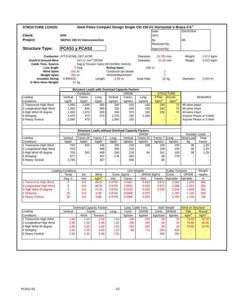
STRUCTURE LOADS: Steel Poles Compact Design Single Ckt 230 kV Horizontal V-Brace 0-5 o
Date:Client: EPR OFS:Project: SIEPAC 230 kV Interconnection By: AB
Reviewed By:
Structure Type: PCAS1 y PCAS2 Approved By:
Conductor: 477.0 KCMIL 26/7 ACSR Diameter: 21.793 mm Weight: 0.976 kg/mOverh'd Ground Wire: 107.17 mm2 OPGW Diameter: 14.00 mm Weight: 0.593 kg/m
Cable Tens. Source: Sag & Tension Calcs 02/13/2004--SAG10Line Angle: 5 Deg. Ruling Span: 150 mWind Span: 250 m Conductor per phase: 2
Weight Span: 350 m OHGW/Attachment: 1Insulator String: V-BRACE Length: 2.60 m Susp Hdw: 20 kg Diameter: 0.254 m
G Wire Hwre Weight: 10 kg
Structure Loads with Overload Capacity FactorsConductor OHGW
Loading Vertical Transv. Long. Vertical Transv. Long. 2*Flat RoundConditions kg/ph kg/ph kg/ph kg/wire kg/wire kg/wire kg/m2 kg/m2
1 Transverse High Wind 1,060 1,500 300 330 510 150 230 72 All wires intact2 Longitudinal High Wind 1,060 600 360 330 240 150 230 72 All wires intact3 High Wind 45 degree 1,060 1,070 300 330 370 150 230 72 All wires intact4 Stringing 1,470 470 270 1,270 150 1,160 - - Anyone Phase or S Wire5 Heavy Vertical 2,590 470 - 1,000 150 - - - Anyone Phase or S Wire
Structure Loads without Overload Capacity FactorsConductor OHGW
Loading Vertical Transv.W Transv.T Long. Vertical Transv.W Transv.T Long. Wind Load DragConditions kg/ph kg/ph kg/ph kg/ph kg/wire kg/wire kg/wire kg/wire kg Factor1 Transverse High Wind 703 523 436 200 218 168 169 100 38 1.202 Longitudinal High Wind 703 - 399 200 218 - 158 100 38 1.203 High Wind 45 degree 703 262 409 200 218 84 161 100 38 1.204 Stringing 977 - 307 176 843 - 96 770 - - 5 Heavy Vertical 1,726 - 307 - 665 - 96 - - -
Loading Conditions Unit Weights Cable Tensions WeightTemp Ice Wind Cond. (kg/m) OHGW (kg/m) Cond. OPGW SpansDeg. C mm kg/m2 Vert. Transv. Vert. Transv. kg/cable kg/cable m
1 Transverse High Wind 0 0.0 48.00 0.9760 1.0461 0.593 0.672 2,500 1,933 3502 Longitudinal High Wind 0 0.0 48.00 0.9760 1.0461 0.593 0.672 2,286 1,815 3503 High Wind 45 degree 0 0.0 24.00 0.9760 0.5230 0.593 0.336 2,346 1,848 3504 Stringing 25 0.0 0.00 0.9760 0.0000 0.593 - 1,760 1,100 3505 Heavy Vertical 25 0.0 0.00 0.9760 0.0000 0.593 - 1,760 1,100 700
Overload Capacity Factors Long. Cable Tens. Add'l Weight Wind on StructureLoading Vertical Transv. Long. Cond. OHGW Cond. OHGW Flat RoundConditions Wind Tension kg/wire kg/wire kg/phase kg/wire kg/m2 kg/m2
1 Transverse High Wind 1.50 1.50 1.50 1.50 100 100 20 10 76.80 48.00 2 Longitudinal High Wind 1.50 1.50 1.50 1.50 100 100 20 10 76.80 48.00 3 High Wind 45 degree 1.50 1.50 1.50 1.50 100 100 20 10 76.80 24.00 4 Stringing 1.50 1.50 1.50 1.50 88 770 294 635 - - 5 Heavy Vertical 1.50 1.50 1.50 1.50 - - 360 250 - -
23/03/2004
REMARKS
Insulator Loads
STRUCTURE
PCAS1-S2 1/2

STRUCTURE LOADS: Steel Poles Compact Design Single Ckt 230 kV Suspension and Angle 5-15o
Date:Client: EPR OFS:Project: SIEPAC 230 kV Interconnection By: AB
Reviewed By:
Structure Type: PCASA Approved By:
Conductor: 477.0 KCMIL 26/7 ACSR Diameter: 21.793 mm Weight: 0.976 kg/mOverh'd Ground Wire: 107.17 mm2 OPGW Diameter: 14.00 mm Weight: 0.593 kg/m
Cable Tens. Source: Sag & Tension Calcs 02/13/2004--SAG10Line Angle: 15 Deg. Ruling Span: 150 mWind Span: 250 m Conductor per phase: 2
Weight Span: 350 m OHGW/Attachment: 1Insulator String: 16 ANSI Class 52-5 Length: 2.60 m Susp Hdw: 20 kg Diameter: 0.254 m
G Wire Hwre Weight: 10 kg
Structure Loads with Overload Capacity FactorsConductor OHGW
Loading Vertical Transv. Long. Vertical Transv. Long. 2*Flat RoundConditions kg/ph kg/ph kg/ph kg/wire kg/wire kg/wire kg/m2 kg/m2
1 Transverse High Wind 1,060 2,800 300 330 1,010 150 230 72 All wires intact2 Longitudinal High Wind 1,060 1,800 360 330 720 150 230 72 All wires intact3 High Wind 45 degree 1,060 2,290 300 330 850 150 230 72 All wires intact4 Long. Load Containment 850 1,110 2,120 270 350 1,320 - - Anyone Phase or S Wire5 Stringing 2,640 1,570 4,190 1,440 490 1,310 - - Anyone Phase or S Wire6 Heavy Vertical 2,940 1,570 - 1,140 490 - - - Anyone Phase or S Wire
Structure Loads without Overload Capacity FactorsConductor OHGW
Loading Vertical Transv.W Transv.T Long. Vertical Transv.W Transv.T Long. Wind Load DragConditions kg/ph kg/ph kg/ph kg/ph kg/wire kg/wire kg/wire kg/wire kg Factor1 Transverse High Wind 703 523 1,305 200 218 168 505 100 38 1.202 Longitudinal High Wind 703 - 1,194 200 218 - 474 100 38 1.203 High Wind 45 degree 703 262 1,225 200 218 84 482 100 38 1.204 Long. Load Containment 703 - 919 1,760 218 - 287 1,100 - - 5 Stringing 1,549 - 919 2,464 843 - 287 770 - - 6 Heavy Vertical 1,726 - 919 - 665 - 287 - - -
Loading Conditions Unit Weights Cable Tensions WeightTemp Ice Wind Cond. (kg/m) OHGW (kg/m) Cond. OPGW SpansDeg. C mm kg/m2 Vert. Transv. Vert. Transv. kg/cable kg/cable m
1 Transverse High Wind 0 0.0 48.00 0.9760 1.0461 0.593 0.672 2,500 1,933 3502 Longitudinal High Wind 0 0.0 48.00 0.9760 1.0461 0.593 0.672 2,286 1,815 3503 High Wind 45 degree 0 0.0 24.00 0.9760 0.5230 0.593 0.336 2,346 1,848 3504 Long. Load Containment 25 0.0 0.00 0.9760 0.0000 0.593 - 1,760 1,100 3505 Stringing 25 0.0 0.00 0.9760 0.0000 0.593 - 1,760 1,100 3506 Heavy Vertical 25 0.0 0.00 0.9760 0.0000 0.593 - 1,760 1,100 700
Overload Capacity Factors Long. Cable Tens. Add'l Weight Wind on StructureLoading Vertical Transv. Long. Cond. OHGW Cond. OHGW Flat RoundConditions Wind Tension kg/wire kg/wire kg/phase kg/wire kg/m2 kg/m2
1 Transverse High Wind 1.50 1.50 1.50 1.50 100 100 20 10 76.80 48.00 2 Longitudinal High Wind 1.50 1.50 1.50 1.50 100 100 20 10 76.80 48.00 3 High Wind 45 degree 1.50 1.50 1.50 1.50 100 100 20 10 76.80 24.00 4 Long. Load Containment 1.20 1.20 1.20 1.20 880 1,100 20 10 - - 5 Stringing 1.70 1.70 1.70 1.70 1,232 770 866 635 - - 6 Heavy Vertical 1.70 1.70 1.70 1.70 - - 360 250 - -
25/03/2004
REMARKS
Insulator Loads
STRUCTURE
PCASA 1/2

STRUCTURE LOADS: Steel Poles Compact Design Single Ckt 69 kV Suspension and Angle 5-15o
Date:Client: EPR OFS:Project: SIEPAC 230 kV Interconnection By: AB
Reviewed By:
Structure Type: PCASA Approved By:
Conductor: 477.0 KCMIL 26/7 ACSR Diameter: 21.793 mm Weight: 0.976 kg/mOverh'd Ground Wire: 107.17 mm2 OPGW Diameter: 14.00 mm Weight: 0.593 kg/m
Cable Tens. Source: Sag & Tension Calcs 02/13/2004--SAG10Line Angle: 15 Deg. Ruling Span: 150 mWind Span: 250 m Conductor per phase: 1
Weight Span: 350 m OHGW/Attachment: 1Insulator String: 6 ANSI Class 52-5 Length: 1.00 m Susp Hdw: 20 kg Diameter: 0.254 m
G Wire Hwre Weight: 10 kg
Structure Loads with Overload Capacity FactorsConductor OHGW
Loading Vertical Transv. Long. Vertical Transv. Long. 2*Flat RoundConditions kg/ph kg/ph kg/ph kg/wire kg/wire kg/wire kg/m2 kg/m2
1 Transverse High Wind 550 1,400 150 330 1,010 150 230 72 All wires intact2 Longitudinal High Wind 550 900 180 330 720 150 230 72 All wires intact3 High Wind 45 degree 550 1,140 150 330 850 150 230 72 All wires intact4 Long. Load Containment 440 560 2,120 270 350 1,320 - - Anyone Phase or S Wire5 Stringing 2,060 790 2,100 1,440 490 1,310 - - Anyone Phase or S Wire6 Heavy Vertical 1,780 790 - 1,140 490 - - - Anyone Phase or S Wire
Structure Loads without Overload Capacity FactorsConductor OHGW
Loading Vertical Transv.W Transv.T Long. Vertical Transv.W Transv.T Long. Wind Load DragConditions kg/ph kg/ph kg/ph kg/ph kg/wire kg/wire kg/wire kg/wire kg Factor1 Transverse High Wind 362 262 653 100 218 168 505 100 15 1.202 Longitudinal High Wind 362 - 597 100 218 - 474 100 15 1.203 High Wind 45 degree 362 131 612 100 218 84 482 100 15 1.204 Long. Load Containment 362 - 459 1,760 218 - 287 1,100 - - 5 Stringing 1,208 - 459 1,232 843 - 287 770 - - 6 Heavy Vertical 1,043 - 459 - 665 - 287 - - -
Loading Conditions Unit Weights Cable Tensions WeightTemp Ice Wind Cond. (kg/m) OHGW (kg/m) Cond. OPGW SpansDeg. C mm kg/m2 Vert. Transv. Vert. Transv. kg/cable kg/cable m
1 Transverse High Wind 0 0.0 48.00 0.9760 1.0461 0.593 0.672 2,500 1,933 3502 Longitudinal High Wind 0 0.0 48.00 0.9760 1.0461 0.593 0.672 2,286 1,815 3503 High Wind 45 degree 0 0.0 24.00 0.9760 0.5230 0.593 0.336 2,346 1,848 3504 Long. Load Containment 25 0.0 0.00 0.9760 0.0000 0.593 - 1,760 1,100 3505 Stringing 25 0.0 0.00 0.9760 0.0000 0.593 - 1,760 1,100 3506 Heavy Vertical 25 0.0 0.00 0.9760 0.0000 0.593 - 1,760 1,100 700
Overload Capacity Factors Long. Cable Tens. Add'l Weight Wind on StructureLoading Vertical Transv. Long. Cond. OHGW Cond. OHGW Flat RoundConditions Wind Tension kg/wire kg/wire kg/phase kg/wire kg/m2 kg/m2
1 Transverse High Wind 1.50 1.50 1.50 1.50 100 100 20 10 76.80 48.00 2 Longitudinal High Wind 1.50 1.50 1.50 1.50 100 100 20 10 76.80 48.00 3 High Wind 45 degree 1.50 1.50 1.50 1.50 100 100 20 10 76.80 24.00 4 Long. Load Containment 1.20 1.20 1.20 1.20 1,760 1,100 20 10 - - 5 Stringing 1.70 1.70 1.70 1.70 1,232 770 866 635 - - 6 Heavy Vertical 1.70 1.70 1.70 1.70 - - 360 250 - -
25/03/2004
STRUCTUREREMARKS
Insulator Loads
PCASA 2/2

STRUCTURE LOADS: Steel Poles Compact Design Single Ckt 230 kV Dead End and Angle 0-30o
Date:Client: EPR OFS: Rev AProject: SIEPAC 230 kV Interconnection By: AB
Reviewed By:
Structure Type: PCAMS Approved By:
Conductor: 477.0 KCMIL 26/7 ACSR Diameter: 21.793 mm Weight: 0.976 kg/mOverh'd Ground Wire: 107.17 mm2 OPGW Diameter: 14.00 mm Weight: 0.593 kg/m
Cable Tens. Source: Sag & Tension Calcs 02/13/2004--SAG10Line Angle: 30 Deg. Ruling Span: 150 mWind Span: 250 m Conductor per phase: 2
Weight Span: 450 m OHGW/Attachment: 1Insulator String: 16 ANSI Class 52-5 Length: 2.60 m Weight: 110 kg Diameter: 0.254 m
G Wire Hwre Weight: 20 kg
Structure Loads with Overload Capacity FactorsConductor OHGW
Loading Vertical Transv. Long. Vertical Transv. Long. 2*Flat RoundConditions kg/ph kg/ph kg/ph kg/wire kg/wire kg/wire kg/m2 kg/m2
1 Transverse High Wind 1,820 4,730 1,500 440 1,760 380 230 72 All wires intact2 Longitudinal High Wind 1,820 3,550 1,260 440 1,410 150 230 72 All wires intact3 High Wind 45 degree 1,820 4,100 1,200 440 1,570 150 230 72 All wires intact4 Temporary deadend EDS 1,460 1,100 4,230 350 350 1,320 - - One or all wires, one side only5 Stringing 3,740 3,100 4,190 1,540 970 1,310 - - Anyone Phase or S Wire6 Heavy Vertical 3,980 3,100 - 1,340 970 - - - Anyone Phase or S Wire
Structure Loads without Overload Capacity FactorsConductor OPGW
Loading Vertical Transv.W Transv.T Long. Vertical Transv.W Transv.T Long. Wind Load DragConditions kg/ph kg/ph kg/ph kg/ph kg/wire kg/wire kg/wire kg/wire kg Factor1 Transverse High Wind 1,208 523 2,588 1,000 287 168 1,001 250 38 1.202 Longitudinal High Wind 1,208 - 2,367 800 287 - 940 100 38 1.203 High Wind 45 degree 1,208 262 2,429 800 287 84 957 100 38 1.204 Temporary deadend EDS 1,208 - 911 3,520 287 - 285 1,100 - - 5 Stringing 2,195 - 1,822 2,464 902 - 569 770 - - 6 Heavy Vertical 2,337 - 1,822 - 784 - 569 - - -
Loading Conditions Unit Weights Cable Tensions WeightTemp Ice Wind Cond. (kg/m) OPGW (kg/m) Cond. OPGW SpansDeg. C mm kg/m2 Vert. Transv. Vert. Transv. kg/cable kg/cable m
1 Transverse High Wind 0 0.0 48.00 0.9760 1.0461 0.593 0.672 2,500 1,933 4502 Longitudinal High Wind 0 0.0 48.00 0.9760 1.0461 0.593 0.672 2,286 1,815 4503 High Wind 45 degree 0 0.0 24.00 0.9760 0.5230 0.593 0.336 2,346 1,848 4504 Temporary deadend EDS 25 0.0 0.00 0.9760 0.0000 0.593 - 1,760 1,100 4505 Stringing 25 0.0 0.00 0.9760 0.0000 0.593 - 1,760 1,100 4506 Heavy Vertical 25 0.0 0.00 0.9760 0.0000 0.593 - 1,760 1,100 900
Overload Capacity Factors Long. Cable Tens. Add'l Weight Wind on StructureLoading Vertical Transv. Long. Cond. OPGW Cond. OPGW Flat RoundConditions Wind Tension kg/wire kg/wire kg/phase kg/wire kg/m2 kg/m2
1 Transverse High Wind 1.50 1.50 1.50 1.50 500 250 110 20 76.80 48.00 2 Longitudinal High Wind 1.50 1.50 1.50 1.50 400 100 110 20 76.80 48.00 3 High Wind 45 degree 1.50 1.50 1.50 1.50 400 100 110 20 76.80 24.00 4 Temporary deadend EDS 1.20 1.20 1.20 1.20 1,760 1,100 110 20 - - 5 Stringing 1.70 1.70 1.70 1.70 1,232 770 1,317 635 - - 6 Heavy Vertical 1.70 1.70 1.70 1.70 - - 580 250 - -
25/03/2004
REMARKS
Insulator Loads
STRUCTURE
PCAMS 1/1
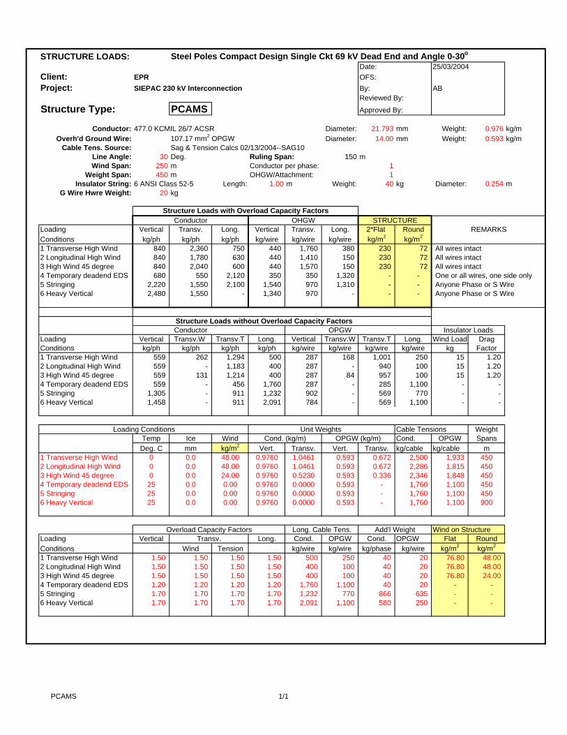
STRUCTURE LOADS: Steel Poles Compact Design Single Ckt 69 kV Dead End and Angle 0-30o
Date:Client: EPR OFS:Project: SIEPAC 230 kV Interconnection By: AB
Reviewed By:
Structure Type: PCAMS Approved By:
Conductor: 477.0 KCMIL 26/7 ACSR Diameter: 21.793 mm Weight: 0.976 kg/mOverh'd Ground Wire: 107.17 mm2 OPGW Diameter: 14.00 mm Weight: 0.593 kg/m
Cable Tens. Source: Sag & Tension Calcs 02/13/2004--SAG10Line Angle: 30 Deg. Ruling Span: 150 mWind Span: 250 m Conductor per phase: 1
Weight Span: 450 m OHGW/Attachment: 1Insulator String: 6 ANSI Class 52-5 Length: 1.00 m Weight: 40 kg Diameter: 0.254 m
G Wire Hwre Weight: 20 kg
Structure Loads with Overload Capacity FactorsConductor OHGW
Loading Vertical Transv. Long. Vertical Transv. Long. 2*Flat RoundConditions kg/ph kg/ph kg/ph kg/wire kg/wire kg/wire kg/m2 kg/m2
1 Transverse High Wind 840 2,360 750 440 1,760 380 230 72 All wires intact2 Longitudinal High Wind 840 1,780 630 440 1,410 150 230 72 All wires intact3 High Wind 45 degree 840 2,040 600 440 1,570 150 230 72 All wires intact4 Temporary deadend EDS 680 550 2,120 350 350 1,320 - - One or all wires, one side only5 Stringing 2,220 1,550 2,100 1,540 970 1,310 - - Anyone Phase or S Wire6 Heavy Vertical 2,480 1,550 - 1,340 970 - - - Anyone Phase or S Wire
Structure Loads without Overload Capacity FactorsConductor OPGW
Loading Vertical Transv.W Transv.T Long. Vertical Transv.W Transv.T Long. Wind Load DragConditions kg/ph kg/ph kg/ph kg/ph kg/wire kg/wire kg/wire kg/wire kg Factor1 Transverse High Wind 559 262 1,294 500 287 168 1,001 250 15 1.202 Longitudinal High Wind 559 - 1,183 400 287 - 940 100 15 1.203 High Wind 45 degree 559 131 1,214 400 287 84 957 100 15 1.204 Temporary deadend EDS 559 - 456 1,760 287 - 285 1,100 - - 5 Stringing 1,305 - 911 1,232 902 - 569 770 - - 6 Heavy Vertical 1,458 - 911 2,091 784 - 569 1,100 - -
Loading Conditions Unit Weights Cable Tensions WeightTemp Ice Wind Cond. (kg/m) OPGW (kg/m) Cond. OPGW SpansDeg. C mm kg/m2 Vert. Transv. Vert. Transv. kg/cable kg/cable m
1 Transverse High Wind 0 0.0 48.00 0.9760 1.0461 0.593 0.672 2,500 1,933 4502 Longitudinal High Wind 0 0.0 48.00 0.9760 1.0461 0.593 0.672 2,286 1,815 4503 High Wind 45 degree 0 0.0 24.00 0.9760 0.5230 0.593 0.336 2,346 1,848 4504 Temporary deadend EDS 25 0.0 0.00 0.9760 0.0000 0.593 - 1,760 1,100 4505 Stringing 25 0.0 0.00 0.9760 0.0000 0.593 - 1,760 1,100 4506 Heavy Vertical 25 0.0 0.00 0.9760 0.0000 0.593 - 1,760 1,100 900
Overload Capacity Factors Long. Cable Tens. Add'l Weight Wind on StructureLoading Vertical Transv. Long. Cond. OPGW Cond. OPGW Flat RoundConditions Wind Tension kg/wire kg/wire kg/phase kg/wire kg/m2 kg/m2
1 Transverse High Wind 1.50 1.50 1.50 1.50 500 250 40 20 76.80 48.00 2 Longitudinal High Wind 1.50 1.50 1.50 1.50 400 100 40 20 76.80 48.00 3 High Wind 45 degree 1.50 1.50 1.50 1.50 400 100 40 20 76.80 24.00 4 Temporary deadend EDS 1.20 1.20 1.20 1.20 1,760 1,100 40 20 - - 5 Stringing 1.70 1.70 1.70 1.70 1,232 770 866 635 - - 6 Heavy Vertical 1.70 1.70 1.70 1.70 2,091 1,100 580 250 - -
25/03/2004
STRUCTUREREMARKS
Insulator Loads
PCAMS 1/1
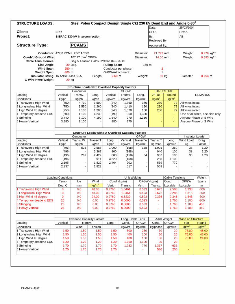
STRUCTURE LOADS: Steel Poles Compact Design Single Ckt 230 kV Dead End and Angle 0-30o
Date:Client: EPR OFS: Rev AProject: SIEPAC 230 kV Interconnection By: AB
Reviewed By:
Structure Type: PCAMS Approved By:
Conductor: 477.0 KCMIL 26/7 ACSR Diameter: 21.793 mm Weight: 0.976 kg/mOverh'd Ground Wire: 107.17 mm2 OPGW Diameter: 14.00 mm Weight: 0.593 kg/m
Cable Tens. Source: Sag & Tension Calcs 02/13/2004--SAG10Line Angle: 30 Deg. Ruling Span: 150 mWind Span: 250 m Conductor per phase: 2
Weight Span: -300 m OHGW/Attachment: 1Insulator String: 16 ANSI Class 52-5 Length: 2.60 m Weight: 30 kg Diameter: 0.254 m
G Wire Hwre Weight: 20 kg
Structure Loads with Overload Capacity FactorsConductor OHGW
Loading Vertical Transv. Long. Vertical Transv. Long. 2*Flat RoundConditions kg/ph kg/ph kg/ph kg/wire kg/wire kg/wire kg/m2 kg/m2
1 Transverse High Wind (750) 4,730 1,500 (240) 1,760 380 230 72 All wires intact2 Longitudinal High Wind (750) 3,550 1,260 (240) 1,410 150 230 72 All wires intact3 High Wind 45 degree (750) 4,100 1,200 (240) 1,570 150 230 72 All wires intact4 Temporary deadend EDS (600) 1,100 4,230 (190) 350 1,320 - - One or all wires, one side only5 Stringing 3,740 3,100 4,190 1,540 970 1,310 - - Anyone Phase or S Wire6 Heavy Vertical 3,980 3,100 - 880 970 - - - Anyone Phase or S Wire
Structure Loads without Overload Capacity FactorsConductor OPGW
Loading Vertical Transv.W Transv.T Long. Vertical Transv.W Transv.T Long. Wind Load DragConditions kg/ph kg/ph kg/ph kg/ph kg/wire kg/wire kg/wire kg/wire kg Factor1 Transverse High Wind (496) 523 2,588 1,000 (158) 168 1,001 250 38 1.202 Longitudinal High Wind (496) - 2,367 800 (158) - 940 100 38 1.203 High Wind 45 degree (496) 262 2,429 800 (158) 84 957 100 38 1.204 Temporary deadend EDS (496) - 911 3,520 (158) - 285 1,100 - - 5 Stringing 2,195 - 1,822 2,464 902 - 569 770 - - 6 Heavy Vertical 2,337 - 1,822 - 517 - 569 - - -
Loading Conditions Unit Weights Cable Tensions WeightTemp Ice Wind Cond. (kg/m) OPGW (kg/m) Cond. OPGW SpansDeg. C mm kg/m2 Vert. Transv. Vert. Transv. kg/cable kg/cable m
1 Transverse High Wind 0 0.0 48.00 0.9760 1.0461 0.593 0.672 2,500 1,933 -3002 Longitudinal High Wind 0 0.0 48.00 0.9760 1.0461 0.593 0.672 2,286 1,815 -3003 High Wind 45 degree 0 0.0 24.00 0.9760 0.5230 0.593 0.336 2,346 1,848 -3004 Temporary deadend EDS 25 0.0 0.00 0.9760 0.0000 0.593 - 1,760 1,100 -3005 Stringing 25 0.0 0.00 0.9760 0.0000 0.593 - 1,760 1,100 4506 Heavy Vertical 25 0.0 0.00 0.9760 0.0000 0.593 - 1,760 1,100 450
Overload Capacity Factors Long. Cable Tens. Add'l Weight Wind on StructureLoading Vertical Transv. Long. Cond. OPGW Cond. OPGW Flat RoundConditions Wind Tension kg/wire kg/wire kg/phase kg/wire kg/m2 kg/m2
1 Transverse High Wind 1.50 1.50 1.50 1.50 500 250 30 20 76.80 48.00 2 Longitudinal High Wind 1.50 1.50 1.50 1.50 400 100 30 20 76.80 48.00 3 High Wind 45 degree 1.50 1.50 1.50 1.50 400 100 30 20 76.80 24.00 4 Temporary deadend EDS 1.20 1.20 1.20 1.20 1,760 1,100 30 20 - - 5 Stringing 1.70 1.70 1.70 1.70 1,232 770 1,317 635 - - 6 Heavy Vertical 1.70 1.70 1.70 1.70 - - 580 250 - -
25/03/2004
REMARKS
Insulator Loads
STRUCTURE
PCAMS-Uplift 1/1

STRUCTURE LOADS: Steel Poles Compact Design Single Ckt 69 kV Dead End and Angle 0-30o
Date:Client: EPR OFS:Project: SIEPAC 230 kV Interconnection By: AB
Reviewed By:
Structure Type: PCAMS Approved By:
Conductor: 477.0 KCMIL 26/7 ACSR Diameter: 21.793 mm Weight: 0.976 kg/mOverh'd Ground Wire: 107.17 mm2 OPGW Diameter: 14.00 mm Weight: 0.593 kg/m
Cable Tens. Source: Sag & Tension Calcs 02/13/2004--SAG10Line Angle: 30 Deg. Ruling Span: 150 mWind Span: 250 m Conductor per phase: 1
Weight Span: -300 m OHGW/Attachment: 1Insulator String: 6 ANSI Class 52-5 Length: 1.00 m Weight: 40 kg Diameter: 0.254 m
G Wire Hwre Weight: 20 kg
Structure Loads with Overload Capacity FactorsConductor OHGW
Loading Vertical Transv. Long. Vertical Transv. Long. 2*Flat RoundConditions kg/ph kg/ph kg/ph kg/wire kg/wire kg/wire kg/m2 kg/m2
1 Transverse High Wind (260) 2,360 750 (240) 1,760 380 230 72 All wires intact2 Longitudinal High Wind (260) 1,780 630 (240) 1,410 150 230 72 All wires intact3 High Wind 45 degree (260) 2,040 600 (240) 1,570 150 230 72 All wires intact4 Temporary deadend EDS (210) 550 2,120 (190) 350 1,320 - - One or all wires, one side only5 Stringing 2,220 1,550 2,100 1,540 970 1,310 - - Anyone Phase or S Wire6 Heavy Vertical 2,480 1,550 - 1,340 970 - - - Anyone Phase or S Wire
Structure Loads without Overload Capacity FactorsConductor OPGW
Loading Vertical Transv.W Transv.T Long. Vertical Transv.W Transv.T Long. Wind Load DragConditions kg/ph kg/ph kg/ph kg/ph kg/wire kg/wire kg/wire kg/wire kg Factor1 Transverse High Wind (173) 262 1,294 500 (158) 168 1,001 250 15 1.202 Longitudinal High Wind (173) - 1,183 400 (158) - 940 100 15 1.203 High Wind 45 degree (173) 131 1,214 400 (158) 84 957 100 15 1.204 Temporary deadend EDS (173) - 456 1,760 (158) - 285 1,100 - - 5 Stringing 1,305 - 911 1,232 902 - 569 770 - - 6 Heavy Vertical 1,458 - 911 - 784 - 569 - - -
Loading Conditions Unit Weights Cable Tensions WeightTemp Ice Wind Cond. (kg/m) OPGW (kg/m) Cond. OPGW SpansDeg. C mm kg/m2 Vert. Transv. Vert. Transv. kg/cable kg/cable m
1 Transverse High Wind 0 0.0 48.00 0.9760 1.0461 0.593 0.672 2,500 1,933 -3002 Longitudinal High Wind 0 0.0 48.00 0.9760 1.0461 0.593 0.672 2,286 1,815 -3003 High Wind 45 degree 0 0.0 24.00 0.9760 0.5230 0.593 0.336 2,346 1,848 -3004 Temporary deadend EDS 25 0.0 0.00 0.9760 0.0000 0.593 - 1,760 1,100 -3005 Stringing 25 0.0 0.00 0.9760 0.0000 0.593 - 1,760 1,100 4506 Heavy Vertical 25 0.0 0.00 0.9760 0.0000 0.593 - 1,760 1,100 900
Overload Capacity Factors Long. Cable Tens. Add'l Weight Wind on StructureLoading Vertical Transv. Long. Cond. OPGW Cond. OPGW Flat RoundConditions Wind Tension kg/wire kg/wire kg/phase kg/wire kg/m2 kg/m2
1 Transverse High Wind 1.50 1.50 1.50 1.50 500 250 40 20 76.80 48.00 2 Longitudinal High Wind 1.50 1.50 1.50 1.50 400 100 40 20 76.80 48.00 3 High Wind 45 degree 1.50 1.50 1.50 1.50 400 100 40 20 76.80 24.00 4 Temporary deadend EDS 1.20 1.20 1.20 1.20 1,760 1,100 40 20 - - 5 Stringing 1.70 1.70 1.70 1.70 1,232 770 866 635 - - 6 Heavy Vertical 1.70 1.70 1.70 1.70 - - 580 250 - -
25/03/2004
STRUCTUREREMARKS
Insulator Loads
PCAMS-Uplift 1/1

STRUCTURE LOADS: Steel Poles Compact Design Single Ckt 230 kV Terminal and Angle 0-50o
Date:Client: EPR OFS: Rev AProject: SIEPAC 230 kV Interconnection By: AB
Reviewed By:Structure Type: PCADS Approved By:
Conductor: 477.0 KCMIL 26/7 ACSR Diameter: 21.793 mm Weight: 0.976 kg/mOverh'd Ground Wire: 107.17 mm2 OPGW Diameter: 14.00 mm Weight: 0.593 kg/m
Cable Tens. Source: Sag & Tension Calcs 02/13/2004--SAG10Line Angle: 50 Deg. Ruling Span: 150 mWind Span: 250 m Conductor per phase: 2
Weight Span: 450 m OHGW/Attachment: 1Insulator String: 16 ANSI Class 52-5 Length: 2.60 m Weight: 110 kg Diameter: 0.254 m
G Wire Hwre Weight: 20 kg
Structure Loads with Overload Capacity FactorsConductor OHGW
Loading Vertical Transv. Long. Vertical Transv. Long. 2*Flat RoundConditions kg/ph kg/ph kg/ph kg/wire kg/wire kg/wire kg/m2 kg/m2
1 Angle Trans High Wind 1,820 7,190 1,360 440 2,710 340 230 72 All wires intact2 Angle Long High Wind 1,820 5,800 1,150 440 2,310 280 230 72 All wires intact3 Angle 45 deg High Wind 1,820 6,400 1,090 440 2,470 280 230 72 All wires intact4 Term Trans High Wind 1,490 3,820 6,800 340 1,480 2,630 230 72 All wires intact, one side only5 Term Long High Wind 1,490 2,900 6,280 340 1,160 2,470 230 72 All wires intact, one side only6 Term 45 deg High Wind 1,490 3,330 6,380 340 1,300 2,520 230 72 All wires intact, one side only7 Stringing 3,740 3,550 3,800 1,540 1,590 1,190 Anyone Phase or S Wire8 Heavy Vertical EDS 3,980 5,060 - 1,760 1,590 - - - One Phase or one S Wire
Structure Loads without Overload Capacity Factors
Loading Vertical Transv.W Transv.T Long. Vertical Transv.W Transv.T Long. Wind Load DragConditions kg/ph kg/ph kg/ph kg/ph kg/wire kg/wire kg/wire kg/wire kg Factor1 Angle Trans High Wind 1,208 523 4,226 906 287 168 1,634 227 38 1.202 Angle Long High Wind 1,208 - 3,864 725 287 - 1,534 181 38 1.203 Angle 45 deg High Wind 1,208 262 3,966 725 287 84 1,562 181 38 1.20 4 Term Trans High Wind 989 392 2,113 4,532 220 168 817 1,752 38 1.20 5 Term Long High Wind 989 - 1,932 4,144 220 - 767 1,645 38 1.20 6 Term 45 deg High Wind 989 196 1,983 4,252 220 84 781 1,675 38 1.20 7 Stringing 2,195 - 2,083 2,233 902 - 930 698 - -8 Heavy Vertical EDS 2,337 - 2,975 - 1,034 - 930 - - -
- Loading Conditions Unit Weights Cable Tensions Weight
Temp Ice Wind Cond. (kg/m) OHGW (kg/m) Cond. OHGW SpansDeg. C mm kg/m2 Vert. Transv. Vert. Transv. kg/cable kg/cable m
1 Angle Trans High Wind 0 0.0 48.00 0.9760 1.0461 0.593 0.672 2,500 1,933 4502 Angle Long High Wind 0 0.0 48.00 0.9760 1.0461 0.593 0.672 2,286 1,815 4503 Angle 45 deg High Wind 0 0.0 24.00 0.9760 0.5230 0.593 0.336 2,346 1,848 4504 Term Trans High Wind 0 0.0 48.00 0.9760 1.0461 0.593 0.672 2,500 1,933 4505 Term Long High Wind 0 0.0 48.00 0.9760 1.0461 0.593 0.672 2,286 1,815 4506 Term 45 deg High Wind 0 0.0 24.00 0.9760 0.5230 0.593 0.336 2,346 1,848 4507 Stringing 25 0.0 0.00 0.9760 0.0000 0.593 - 1,760 1,100 4508 Heavy Vertical EDS 25 0.0 0.00 0.9760 0.0000 0.593 - 1,760 1,100 900
Overload Capacity Factors Long. Cable Tens. Add'l Weight Wind on StructureLoading Vertical Transv. Long. Cond. OHGW Cond. OHGW Flat RoundConditions Wind Tension kg/phase kg/wire kg/phase kg/wire kg/m2 kg/m2
1 Angle Trans High Wind 1.50 1.50 1.50 1.50 500 250 110 20 76.80 48.00 2 Angle Long High Wind 1.50 1.50 1.50 1.50 400 200 110 20 76.80 48.00 3 Angle 45 deg High Wind 1.50 1.50 1.50 1.50 400 200 110 20 38.40 24.00 4 Term Trans High Wind 1.50 1.50 1.50 1.50 2,500 1,933 110 20 76.80 48.00 5 Term Long High Wind 1.50 1.50 1.50 1.50 2,286 1,815 110 20 76.80 48.00 6 Term 45 deg High Wind 1.50 1.50 1.50 1.50 2,346 1,848 110 20 38.40 24.00 7 Stringing 1.70 1.70 1.70 1.70 1,232 770 1,317 635 8 Heavy Vertical EDS 1.70 1.70 1.70 1.70 - - 580 250 - -
Conductor OHGW
25/03/2004
REMARKS
Insulator Loads
STRUCTURE
PCADS-50 1/2
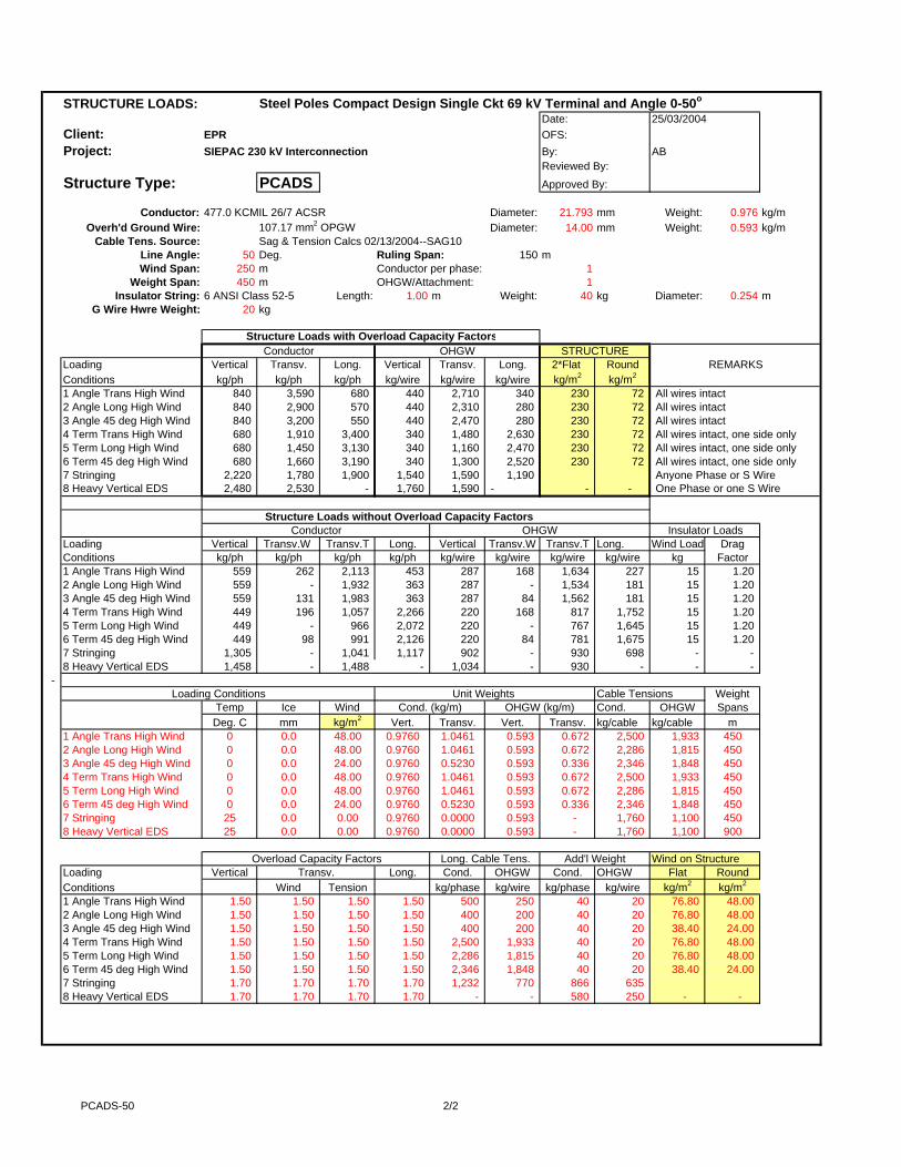
STRUCTURE LOADS: Steel Poles Compact Design Single Ckt 69 kV Terminal and Angle 0-50o
Date:Client: EPR OFS:Project: SIEPAC 230 kV Interconnection By: AB
Reviewed By:Structure Type: PCADS Approved By:
Conductor: 477.0 KCMIL 26/7 ACSR Diameter: 21.793 mm Weight: 0.976 kg/mOverh'd Ground Wire: 107.17 mm2 OPGW Diameter: 14.00 mm Weight: 0.593 kg/m
Cable Tens. Source: Sag & Tension Calcs 02/13/2004--SAG10Line Angle: 50 Deg. Ruling Span: 150 mWind Span: 250 m Conductor per phase: 1
Weight Span: 450 m OHGW/Attachment: 1Insulator String: 6 ANSI Class 52-5 Length: 1.00 m Weight: 40 kg Diameter: 0.254 m
G Wire Hwre Weight: 20 kg
Structure Loads with Overload Capacity FactorsConductor OHGW
Loading Vertical Transv. Long. Vertical Transv. Long. 2*Flat RoundConditions kg/ph kg/ph kg/ph kg/wire kg/wire kg/wire kg/m2 kg/m2
1 Angle Trans High Wind 840 3,590 680 440 2,710 340 230 72 All wires intact2 Angle Long High Wind 840 2,900 570 440 2,310 280 230 72 All wires intact3 Angle 45 deg High Wind 840 3,200 550 440 2,470 280 230 72 All wires intact4 Term Trans High Wind 680 1,910 3,400 340 1,480 2,630 230 72 All wires intact, one side only5 Term Long High Wind 680 1,450 3,130 340 1,160 2,470 230 72 All wires intact, one side only6 Term 45 deg High Wind 680 1,660 3,190 340 1,300 2,520 230 72 All wires intact, one side only7 Stringing 2,220 1,780 1,900 1,540 1,590 1,190 Anyone Phase or S Wire8 Heavy Vertical EDS 2,480 2,530 - 1,760 1,590 - - - One Phase or one S Wire
Structure Loads without Overload Capacity Factors
Loading Vertical Transv.W Transv.T Long. Vertical Transv.W Transv.T Long. Wind Load DragConditions kg/ph kg/ph kg/ph kg/ph kg/wire kg/wire kg/wire kg/wire kg Factor1 Angle Trans High Wind 559 262 2,113 453 287 168 1,634 227 15 1.202 Angle Long High Wind 559 - 1,932 363 287 - 1,534 181 15 1.203 Angle 45 deg High Wind 559 131 1,983 363 287 84 1,562 181 15 1.20 4 Term Trans High Wind 449 196 1,057 2,266 220 168 817 1,752 15 1.20 5 Term Long High Wind 449 - 966 2,072 220 - 767 1,645 15 1.20 6 Term 45 deg High Wind 449 98 991 2,126 220 84 781 1,675 15 1.20 7 Stringing 1,305 - 1,041 1,117 902 - 930 698 - -8 Heavy Vertical EDS 1,458 - 1,488 - 1,034 - 930 - - -
- Loading Conditions Unit Weights Cable Tensions Weight
Temp Ice Wind Cond. (kg/m) OHGW (kg/m) Cond. OHGW SpansDeg. C mm kg/m2 Vert. Transv. Vert. Transv. kg/cable kg/cable m
1 Angle Trans High Wind 0 0.0 48.00 0.9760 1.0461 0.593 0.672 2,500 1,933 4502 Angle Long High Wind 0 0.0 48.00 0.9760 1.0461 0.593 0.672 2,286 1,815 4503 Angle 45 deg High Wind 0 0.0 24.00 0.9760 0.5230 0.593 0.336 2,346 1,848 4504 Term Trans High Wind 0 0.0 48.00 0.9760 1.0461 0.593 0.672 2,500 1,933 4505 Term Long High Wind 0 0.0 48.00 0.9760 1.0461 0.593 0.672 2,286 1,815 4506 Term 45 deg High Wind 0 0.0 24.00 0.9760 0.5230 0.593 0.336 2,346 1,848 4507 Stringing 25 0.0 0.00 0.9760 0.0000 0.593 - 1,760 1,100 4508 Heavy Vertical EDS 25 0.0 0.00 0.9760 0.0000 0.593 - 1,760 1,100 900
Overload Capacity Factors Long. Cable Tens. Add'l Weight Wind on StructureLoading Vertical Transv. Long. Cond. OHGW Cond. OHGW Flat RoundConditions Wind Tension kg/phase kg/wire kg/phase kg/wire kg/m2 kg/m2
1 Angle Trans High Wind 1.50 1.50 1.50 1.50 500 250 40 20 76.80 48.00 2 Angle Long High Wind 1.50 1.50 1.50 1.50 400 200 40 20 76.80 48.00 3 Angle 45 deg High Wind 1.50 1.50 1.50 1.50 400 200 40 20 38.40 24.00 4 Term Trans High Wind 1.50 1.50 1.50 1.50 2,500 1,933 40 20 76.80 48.00 5 Term Long High Wind 1.50 1.50 1.50 1.50 2,286 1,815 40 20 76.80 48.00 6 Term 45 deg High Wind 1.50 1.50 1.50 1.50 2,346 1,848 40 20 38.40 24.00 7 Stringing 1.70 1.70 1.70 1.70 1,232 770 866 635 8 Heavy Vertical EDS 1.70 1.70 1.70 1.70 - - 580 250 - -
25/03/2004
STRUCTUREREMARKS
Conductor OHGW Insulator Loads
PCADS-50 2/2
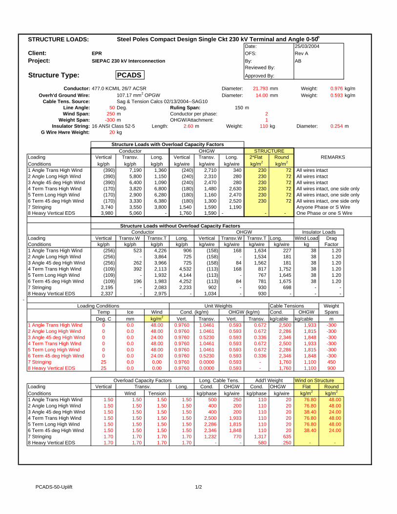
STRUCTURE LOADS: Steel Poles Compact Design Single Ckt 230 kV Terminal and Angle 0-50o
Date:Client: EPR OFS: Rev AProject: SIEPAC 230 kV Interconnection By: AB
Reviewed By:
Structure Type: PCADS Approved By:
Conductor: 477.0 KCMIL 26/7 ACSR Diameter: 21.793 mm Weight: 0.976 kg/mOverh'd Ground Wire: 107.17 mm2 OPGW Diameter: 14.00 mm Weight: 0.593 kg/m
Cable Tens. Source: Sag & Tension Calcs 02/13/2004--SAG10Line Angle: 50 Deg. Ruling Span: 150 mWind Span: 250 m Conductor per phase: 2
Weight Span: -300 m OHGW/Attachment: 1Insulator String: 16 ANSI Class 52-5 Length: 2.60 m Weight: 110 kg Diameter: 0.254 m
G Wire Hwre Weight: 20 kg
Structure Loads with Overload Capacity FactorsConductor OHGW
Loading Vertical Transv. Long. Vertical Transv. Long. 2*Flat RoundConditions kg/ph kg/ph kg/ph kg/wire kg/wire kg/wire kg/m2 kg/m2
1 Angle Trans High Wind (390) 7,190 1,360 (240) 2,710 340 230 72 All wires intact2 Angle Long High Wind (390) 5,800 1,150 (240) 2,310 280 230 72 All wires intact3 Angle 45 deg High Wind (390) 6,400 1,090 (240) 2,470 280 230 72 All wires intact4 Term Trans High Wind (170) 3,820 6,800 (180) 1,480 2,630 230 72 All wires intact, one side only5 Term Long High Wind (170) 2,900 6,280 (180) 1,160 2,470 230 72 All wires intact, one side only6 Term 45 deg High Wind (170) 3,330 6,380 (180) 1,300 2,520 230 72 All wires intact, one side only7 Stringing 3,740 3,550 3,800 1,540 1,590 1,190 Anyone Phase or S Wire8 Heavy Vertical EDS 3,980 5,060 - 1,760 1,590 - - - One Phase or one S Wire
Structure Loads without Overload Capacity Factors
Loading Vertical Transv.W Transv.T Long. Vertical Transv.W Transv.T Long. Wind Load DragConditions kg/ph kg/ph kg/ph kg/ph kg/wire kg/wire kg/wire kg/wire kg Factor1 Angle Trans High Wind (256) 523 4,226 906 (158) 168 1,634 227 38 1.202 Angle Long High Wind (256) - 3,864 725 (158) - 1,534 181 38 1.203 Angle 45 deg High Wind (256) 262 3,966 725 (158) 84 1,562 181 38 1.20 4 Term Trans High Wind (109) 392 2,113 4,532 (113) 168 817 1,752 38 1.20 5 Term Long High Wind (109) - 1,932 4,144 (113) - 767 1,645 38 1.20 6 Term 45 deg High Wind (109) 196 1,983 4,252 (113) 84 781 1,675 38 1.20 7 Stringing 2,195 - 2,083 2,233 902 - 930 698 - -8 Heavy Vertical EDS 2,337 - 2,975 - 1,034 - 930 - - -
- Loading Conditions Unit Weights Cable Tensions Weight
Temp Ice Wind Cond. (kg/m) OHGW (kg/m) Cond. OHGW SpansDeg. C mm kg/m2 Vert. Transv. Vert. Transv. kg/cable kg/cable m
1 Angle Trans High Wind 0 0.0 48.00 0.9760 1.0461 0.593 0.672 2,500 1,933 -3002 Angle Long High Wind 0 0.0 48.00 0.9760 1.0461 0.593 0.672 2,286 1,815 -3003 Angle 45 deg High Wind 0 0.0 24.00 0.9760 0.5230 0.593 0.336 2,346 1,848 -3004 Term Trans High Wind 0 0.0 48.00 0.9760 1.0461 0.593 0.672 2,500 1,933 -3005 Term Long High Wind 0 0.0 48.00 0.9760 1.0461 0.593 0.672 2,286 1,815 -3006 Term 45 deg High Wind 0 0.0 24.00 0.9760 0.5230 0.593 0.336 2,346 1,848 -3007 Stringing 25 0.0 0.00 0.9760 0.0000 0.593 - 1,760 1,100 4508 Heavy Vertical EDS 25 0.0 0.00 0.9760 0.0000 0.593 - 1,760 1,100 900
Overload Capacity Factors Long. Cable Tens. Add'l Weight Wind on StructureLoading Vertical Transv. Long. Cond. OHGW Cond. OHGW Flat RoundConditions Wind Tension kg/phase kg/wire kg/phase kg/wire kg/m2 kg/m2
1 Angle Trans High Wind 1.50 1.50 1.50 1.50 500 250 110 20 76.80 48.00 2 Angle Long High Wind 1.50 1.50 1.50 1.50 400 200 110 20 76.80 48.00 3 Angle 45 deg High Wind 1.50 1.50 1.50 1.50 400 200 110 20 38.40 24.00 4 Term Trans High Wind 1.50 1.50 1.50 1.50 2,500 1,933 110 20 76.80 48.00 5 Term Long High Wind 1.50 1.50 1.50 1.50 2,286 1,815 110 20 76.80 48.00 6 Term 45 deg High Wind 1.50 1.50 1.50 1.50 2,346 1,848 110 20 38.40 24.00 7 Stringing 1.70 1.70 1.70 1.70 1,232 770 1,317 635 8 Heavy Vertical EDS 1.70 1.70 1.70 1.70 - - 580 250 - -
Conductor OHGW
25/03/2004
REMARKS
Insulator Loads
STRUCTURE
PCADS-50-Uplift 1/2

STRUCTURE LOADS: Steel Poles Compact Design Single Ckt 69 kV Terminal and Angle 0-50o
Date:Client: EPR OFS:Project: SIEPAC 230 kV Interconnection By: AB
Reviewed By:
Structure Type: PCADS Approved By:
Conductor: 477.0 KCMIL 26/7 ACSR Diameter: 21.793 mm Weight: 0.976 kg/mOverh'd Ground Wire: 107.17 mm2 OPGW Diameter: 14.00 mm Weight: 0.593 kg/m
Cable Tens. Source: Sag & Tension Calcs 02/13/2004--SAG10Line Angle: 50 Deg. Ruling Span: 150 mWind Span: 250 m Conductor per phase: 1
Weight Span: -300 m OHGW/Attachment: 1Insulator String: 6 ANSI Class 52-5 Length: 1.00 m Weight: 40 kg Diameter: 0.254 m
G Wire Hwre Weight: 20 kg
Structure Loads with Overload Capacity FactorsConductor OHGW
Loading Vertical Transv. Long. Vertical Transv. Long. 2*Flat RoundConditions kg/ph kg/ph kg/ph kg/wire kg/wire kg/wire kg/m2 kg/m2
1 Angle Trans High Wind (260) 3,590 680 (240) 2,710 340 230 72 All wires intact2 Angle Long High Wind (260) 2,900 570 (240) 2,310 280 230 72 All wires intact3 Angle 45 deg High Wind (260) 3,200 550 (240) 2,470 280 230 72 All wires intact4 Term Trans High Wind (150) 1,910 3,400 (180) 1,480 2,630 230 72 All wires intact, one side only5 Term Long High Wind (150) 1,450 3,130 (180) 1,160 2,470 230 72 All wires intact, one side only6 Term 45 deg High Wind (150) 1,660 3,190 (180) 1,300 2,520 230 72 All wires intact, one side only7 Stringing 2,220 1,780 1,900 1,540 1,590 1,190 Anyone Phase or S Wire8 Heavy Vertical EDS 2,480 2,530 - 1,760 1,590 - - - One Phase or one S Wire
Structure Loads without Overload Capacity Factors
Loading Vertical Transv.W Transv.T Long. Vertical Transv.W Transv.T Long. Wind Load DragConditions kg/ph kg/ph kg/ph kg/ph kg/wire kg/wire kg/wire kg/wire kg Factor1 Angle Trans High Wind (173) 262 2,113 453 (158) 168 1,634 227 15 1.202 Angle Long High Wind (173) - 1,932 363 (158) - 1,534 181 15 1.203 Angle 45 deg High Wind (173) 131 1,983 363 (158) 84 1,562 181 15 1.20 4 Term Trans High Wind (100) 196 1,057 2,266 (113) 168 817 1,752 15 1.20 5 Term Long High Wind (100) - 966 2,072 (113) - 767 1,645 15 1.20 6 Term 45 deg High Wind (100) 98 991 2,126 (113) 84 781 1,675 15 1.20 7 Stringing 1,305 - 1,041 1,117 902 - 930 698 - -8 Heavy Vertical EDS 1,458 - 1,488 - 1,034 - 930 - - -
- Loading Conditions Unit Weights Cable Tensions Weight
Temp Ice Wind Cond. (kg/m) OHGW (kg/m) Cond. OHGW SpansDeg. C mm kg/m2 Vert. Transv. Vert. Transv. kg/cable kg/cable m
1 Angle Trans High Wind 0 0.0 48.00 0.9760 1.0461 0.593 0.672 2,500 1,933 -3002 Angle Long High Wind 0 0.0 48.00 0.9760 1.0461 0.593 0.672 2,286 1,815 -3003 Angle 45 deg High Wind 0 0.0 24.00 0.9760 0.5230 0.593 0.336 2,346 1,848 -3004 Term Trans High Wind 0 0.0 48.00 0.9760 1.0461 0.593 0.672 2,500 1,933 -3005 Term Long High Wind 0 0.0 48.00 0.9760 1.0461 0.593 0.672 2,286 1,815 -3006 Term 45 deg High Wind 0 0.0 24.00 0.9760 0.5230 0.593 0.336 2,346 1,848 -3007 Stringing 25 0.0 0.00 0.9760 0.0000 0.593 - 1,760 1,100 4508 Heavy Vertical EDS 25 0.0 0.00 0.9760 0.0000 0.593 - 1,760 1,100 900
Overload Capacity Factors Long. Cable Tens. Add'l Weight Wind on StructureLoading Vertical Transv. Long. Cond. OHGW Cond. OHGW Flat RoundConditions Wind Tension kg/phase kg/wire kg/phase kg/wire kg/m2 kg/m2
1 Angle Trans High Wind 1.50 1.50 1.50 1.50 500 250 40 20 76.80 48.00 2 Angle Long High Wind 1.50 1.50 1.50 1.50 400 200 40 20 76.80 48.00 3 Angle 45 deg High Wind 1.50 1.50 1.50 1.50 400 200 40 20 38.40 24.00 4 Term Trans High Wind 1.50 1.50 1.50 1.50 2,500 1,933 40 20 76.80 48.00 5 Term Long High Wind 1.50 1.50 1.50 1.50 2,286 1,815 40 20 76.80 48.00 6 Term 45 deg High Wind 1.50 1.50 1.50 1.50 2,346 1,848 40 20 38.40 24.00 7 Stringing 1.70 1.70 1.70 1.70 1,232 770 866 635 8 Heavy Vertical EDS 1.70 1.70 1.70 1.70 - - 580 250 - -
25/03/2004
STRUCTUREREMARKS
Conductor OHGW Insulator Loads
PCADS-50-Uplift 2/2

STRUCTURE LOADS: Steel Poles Compact Design Single Ckt 230 kV Terminal and Angle 0-50o
Date:Client: EPR OFS:Project: SIEPAC 230 kV Interconnection By: AB
Reviewed By:
Structure Type: PCADS Approved By:
Conductor: 477.0 KCMIL 26/7 ACSR Diameter: 21.793 mm Weight: 0.976 kg/mOverh'd Ground Wire: 107.17 mm2 OPGW Diameter: 14.00 mm Weight: 0.593 kg/m
Cable Tens. Source: Sag & Tension Calcs 02/13/2004--SAG10Line Angle: 0 Deg. Ruling Span: 150 mWind Span: 250 m Conductor per phase: 2
Weight Span: 450 m OHGW/Attachment: 1Insulator String: 16 ANSI Class 52-5 Length: 2.60 m Weight: 110 kg Diameter: 0.254 m
G Wire Hwre Weight: 20 kg
Structure Loads with Overload Capacity FactorsConductor OHGW
Loading Vertical Transv. Long. Vertical Transv. Long. 2*Flat RoundConditions kg/ph kg/ph kg/ph kg/wire kg/wire kg/wire kg/m2 kg/m2
1 Angle Trans High Wind 1,820 850 1,500 440 260 380 230 72 All wires intact2 Angle Long High Wind 1,820 - 1,260 440 - 300 230 72 All wires intact3 Angle 45 deg High Wind 1,820 450 1,200 440 130 300 230 72 All wires intact4 Term Trans High Wind 1,490 650 7,500 340 260 2,900 230 72 All wires intact, one side only5 Term Long High Wind 1,490 - 6,920 340 - 2,730 230 72 All wires intact, one side only6 Term 45 deg High Wind 1,490 360 7,040 340 130 2,780 230 72 All wires intact, one side only7 Stringing 3,740 - 4,190 1,540 - 1,310 Anyone Phase or S Wire8 Heavy Vertical EDS 3,980 - - 1,760 - - - - One Phase or one S Wire
Structure Loads without Overload Capacity Factors
Loading Vertical Transv.W Transv.T Long. Vertical Transv.W Transv.T Long. Wind Load DragConditions kg/ph kg/ph kg/ph kg/ph kg/wire kg/wire kg/wire kg/wire kg Factor1 Angle Trans High Wind 1,208 523 - 1,000 287 168 - 250 38 1.202 Angle Long High Wind 1,208 - - 800 287 - - 200 38 1.203 Angle 45 deg High Wind 1,208 262 - 800 287 84 - 200 38 1.20 4 Term Trans High Wind 989 392 - 5,000 220 168 - 1,933 38 1.20 5 Term Long High Wind 989 - - 4,572 220 - - 1,815 38 1.20 6 Term 45 deg High Wind 989 196 - 4,692 220 84 - 1,848 38 1.20 7 Stringing 2,195 - - 2,464 902 - - 770 - -8 Heavy Vertical EDS 2,337 - - - 1,034 - - - - -
- Loading Conditions Unit Weights Cable Tensions Weight
Temp Ice Wind Cond. (kg/m) OHGW (kg/m) Cond. OHGW SpansDeg. C mm kg/m2 Vert. Transv. Vert. Transv. kg/cable kg/cable m
1 Angle Trans High Wind 0 0.0 48.00 0.9760 1.0461 0.593 0.672 2,500 1,933 4502 Angle Long High Wind 0 0.0 48.00 0.9760 1.0461 0.593 0.672 2,286 1,815 4503 Angle 45 deg High Wind 0 0.0 24.00 0.9760 0.5230 0.593 0.336 2,346 1,848 4504 Term Trans High Wind 0 0.0 48.00 0.9760 1.0461 0.593 0.672 2,500 1,933 4505 Term Long High Wind 0 0.0 48.00 0.9760 1.0461 0.593 0.672 2,286 1,815 4506 Term 45 deg High Wind 0 0.0 24.00 0.9760 0.5230 0.593 0.336 2,346 1,848 4507 Stringing 25 0.0 0.00 0.9760 0.0000 0.593 - 1,760 1,100 4508 Heavy Vertical EDS 25 0.0 0.00 0.9760 0.0000 0.593 - 1,760 1,100 900
Overload Capacity Factors Long. Cable Tens. Add'l Weight Wind on StructureLoading Vertical Transv. Long. Cond. OHGW Cond. OHGW Flat RoundConditions Wind Tension kg/phase kg/wire kg/phase kg/wire kg/m2 kg/m2
1 Angle Trans High Wind 1.50 1.50 1.50 1.50 500 250 110 20 76.80 48.00 2 Angle Long High Wind 1.50 1.50 1.50 1.50 400 200 110 20 76.80 48.00 3 Angle 45 deg High Wind 1.50 1.50 1.50 1.50 400 200 110 20 38.40 24.00 4 Term Trans High Wind 1.50 1.50 1.50 1.50 2,500 1,933 110 20 76.80 48.00 5 Term Long High Wind 1.50 1.50 1.50 1.50 2,286 1,815 110 20 76.80 48.00 6 Term 45 deg High Wind 1.50 1.50 1.50 1.50 2,346 1,848 110 20 38.40 24.00 7 Stringing 1.70 1.70 1.70 1.70 1,232 770 1,317 635 8 Heavy Vertical EDS 1.70 1.70 1.70 1.70 - - 580 250 - -
Conductor OHGW
28/05/2004
REMARKS
Insulator Loads
STRUCTURE
PCADS-0 1/2

STRUCTURE LOADS: Steel Poles Compact Design Single Ckt 69 kV Terminal and Angle 0-50o
Date:Client: EPR OFS:Project: SIEPAC 230 kV Interconnection By: AB
Reviewed By:
Structure Type: PCADS Approved By:
Conductor: 477.0 KCMIL 26/7 ACSR Diameter: 21.793 mm Weight: 0.976 kg/mOverh'd Ground Wire: 107.17 mm2 OPGW Diameter: 14.00 mm Weight: 0.593 kg/m
Cable Tens. Source: Sag & Tension Calcs 02/13/2004--SAG10Line Angle: 0 Deg. Ruling Span: 150 mWind Span: 250 m Conductor per phase: 1
Weight Span: 450 m OHGW/Attachment: 1Insulator String: 6 ANSI Class 52-5 Length: 1.00 m Weight: 40 kg Diameter: 0.254 m
G Wire Hwre Weight: 20 kg
Structure Loads with Overload Capacity FactorsConductor OHGW
Loading Vertical Transv. Long. Vertical Transv. Long. 2*Flat RoundConditions kg/ph kg/ph kg/ph kg/wire kg/wire kg/wire kg/m2 kg/m2
1 Angle Trans High Wind 840 420 750 440 260 380 230 72 All wires intact2 Angle Long High Wind 840 - 630 440 - 300 230 72 All wires intact3 Angle 45 deg High Wind 840 220 600 440 130 300 230 72 All wires intact4 Term Trans High Wind 680 320 3,750 340 260 2,900 230 72 All wires intact, one side only5 Term Long High Wind 680 - 3,460 340 - 2,730 230 72 All wires intact, one side only6 Term 45 deg High Wind 680 170 3,520 340 130 2,780 230 72 All wires intact, one side only7 Stringing 2,220 - 2,100 1,540 - 1,310 Anyone Phase or S Wire8 Heavy Vertical EDS 2,480 - - 1,760 - - - - One Phase or one S Wire
Structure Loads without Overload Capacity Factors
Loading Vertical Transv.W Transv.T Long. Vertical Transv.W Transv.T Long. Wind Load DragConditions kg/ph kg/ph kg/ph kg/ph kg/wire kg/wire kg/wire kg/wire kg Factor1 Angle Trans High Wind 559 262 - 500 287 168 - 250 15 1.202 Angle Long High Wind 559 - - 400 287 - - 200 15 1.203 Angle 45 deg High Wind 559 131 - 400 287 84 - 200 15 1.20 4 Term Trans High Wind 449 196 - 2,500 220 168 - 1,933 15 1.20 5 Term Long High Wind 449 - - 2,286 220 - - 1,815 15 1.20 6 Term 45 deg High Wind 449 98 - 2,346 220 84 - 1,848 15 1.20 7 Stringing 1,305 - - 1,232 902 - - 770 - -8 Heavy Vertical EDS 1,458 - - - 1,034 - - - - -
- Loading Conditions Unit Weights Cable Tensions Weight
Temp Ice Wind Cond. (kg/m) OHGW (kg/m) Cond. OHGW SpansDeg. C mm kg/m2 Vert. Transv. Vert. Transv. kg/cable kg/cable m
1 Angle Trans High Wind 0 0.0 48.00 0.9760 1.0461 0.593 0.672 2,500 1,933 4502 Angle Long High Wind 0 0.0 48.00 0.9760 1.0461 0.593 0.672 2,286 1,815 4503 Angle 45 deg High Wind 0 0.0 24.00 0.9760 0.5230 0.593 0.336 2,346 1,848 4504 Term Trans High Wind 0 0.0 48.00 0.9760 1.0461 0.593 0.672 2,500 1,933 4505 Term Long High Wind 0 0.0 48.00 0.9760 1.0461 0.593 0.672 2,286 1,815 4506 Term 45 deg High Wind 0 0.0 24.00 0.9760 0.5230 0.593 0.336 2,346 1,848 4507 Stringing 25 0.0 0.00 0.9760 0.0000 0.593 - 1,760 1,100 4508 Heavy Vertical EDS 25 0.0 0.00 0.9760 0.0000 0.593 - 1,760 1,100 900
Overload Capacity Factors Long. Cable Tens. Add'l Weight Wind on StructureLoading Vertical Transv. Long. Cond. OHGW Cond. OHGW Flat RoundConditions Wind Tension kg/phase kg/wire kg/phase kg/wire kg/m2 kg/m2
1 Angle Trans High Wind 1.50 1.50 1.50 1.50 500 250 40 20 76.80 48.00 2 Angle Long High Wind 1.50 1.50 1.50 1.50 400 200 40 20 76.80 48.00 3 Angle 45 deg High Wind 1.50 1.50 1.50 1.50 400 200 40 20 38.40 24.00 4 Term Trans High Wind 1.50 1.50 1.50 1.50 2,500 1,933 40 20 76.80 48.00 5 Term Long High Wind 1.50 1.50 1.50 1.50 2,286 1,815 40 20 76.80 48.00 6 Term 45 deg High Wind 1.50 1.50 1.50 1.50 2,346 1,848 40 20 38.40 24.00 7 Stringing 1.70 1.70 1.70 1.70 1,232 770 866 635 8 Heavy Vertical EDS 1.70 1.70 1.70 1.70 - - 580 250 - -
28/05/2004
STRUCTUREREMARKS
Conductor OHGW Insulator Loads
PCADS-0 2/2
ANEXO 30A
Hojas de Cálculo de las Estructuras Compactas con Postes de Concreto
(PCCS1, PCCS2, PCCSA, PCCMS, PCCDS)
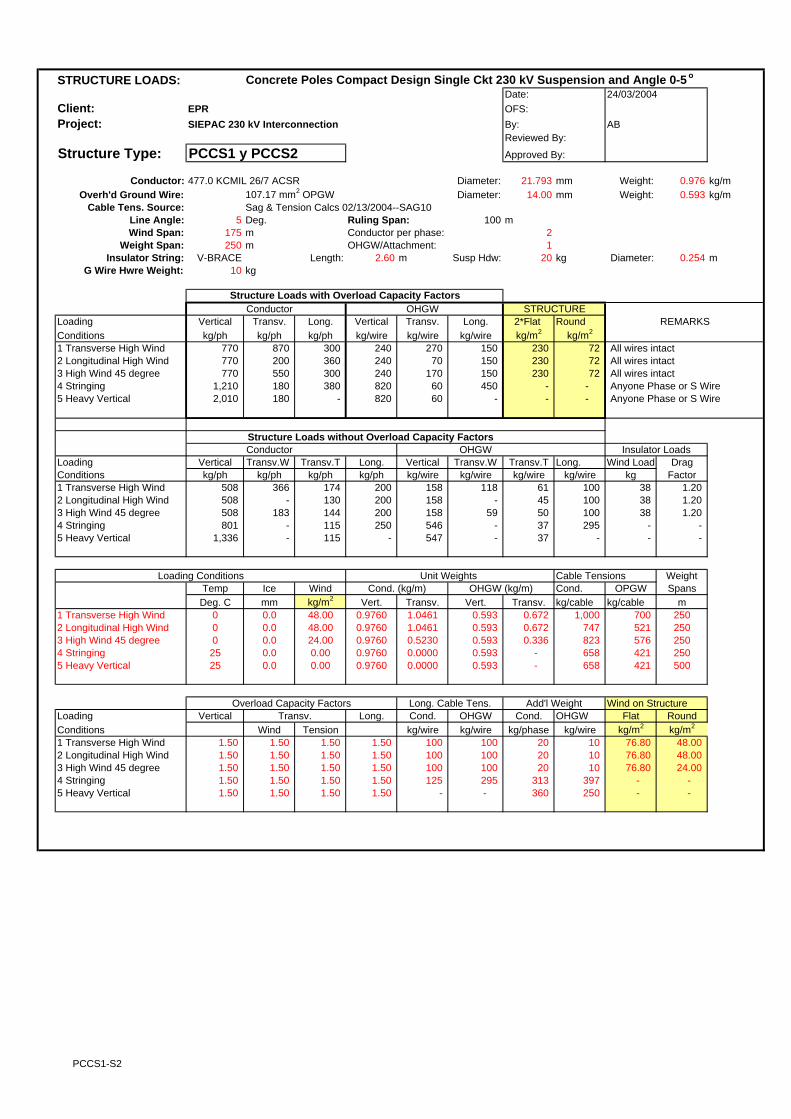
STRUCTURE LOADS: Concrete Poles Compact Design Single Ckt 230 kV Suspension and Angle 0-5 o
Date:Client: EPR OFS:Project: SIEPAC 230 kV Interconnection By: AB
Reviewed By:
Structure Type: PCCS1 y PCCS2 Approved By:
Conductor: 477.0 KCMIL 26/7 ACSR Diameter: 21.793 mm Weight: 0.976 kg/mOverh'd Ground Wire: 107.17 mm2 OPGW Diameter: 14.00 mm Weight: 0.593 kg/m
Cable Tens. Source: Sag & Tension Calcs 02/13/2004--SAG10Line Angle: 5 Deg. Ruling Span: 100 mWind Span: 175 m Conductor per phase: 2
Weight Span: 250 m OHGW/Attachment: 1Insulator String: V-BRACE Length: 2.60 m Susp Hdw: 20 kg Diameter: 0.254 m
G Wire Hwre Weight: 10 kg
Structure Loads with Overload Capacity FactorsConductor OHGW
Loading Vertical Transv. Long. Vertical Transv. Long. 2*Flat RoundConditions kg/ph kg/ph kg/ph kg/wire kg/wire kg/wire kg/m2 kg/m2
1 Transverse High Wind 770 870 300 240 270 150 230 72 All wires intact2 Longitudinal High Wind 770 200 360 240 70 150 230 72 All wires intact3 High Wind 45 degree 770 550 300 240 170 150 230 72 All wires intact4 Stringing 1,210 180 380 820 60 450 - - Anyone Phase or S Wire5 Heavy Vertical 2,010 180 - 820 60 - - - Anyone Phase or S Wire
Structure Loads without Overload Capacity FactorsConductor OHGW
Loading Vertical Transv.W Transv.T Long. Vertical Transv.W Transv.T Long. Wind Load DragConditions kg/ph kg/ph kg/ph kg/ph kg/wire kg/wire kg/wire kg/wire kg Factor1 Transverse High Wind 508 366 174 200 158 118 61 100 38 1.202 Longitudinal High Wind 508 - 130 200 158 - 45 100 38 1.203 High Wind 45 degree 508 183 144 200 158 59 50 100 38 1.204 Stringing 801 - 115 250 546 - 37 295 - - 5 Heavy Vertical 1,336 - 115 - 547 - 37 - - -
Loading Conditions Unit Weights Cable Tensions WeightTemp Ice Wind Cond. (kg/m) OHGW (kg/m) Cond. OPGW SpansDeg. C mm kg/m2 Vert. Transv. Vert. Transv. kg/cable kg/cable m
1 Transverse High Wind 0 0.0 48.00 0.9760 1.0461 0.593 0.672 1,000 700 2502 Longitudinal High Wind 0 0.0 48.00 0.9760 1.0461 0.593 0.672 747 521 2503 High Wind 45 degree 0 0.0 24.00 0.9760 0.5230 0.593 0.336 823 576 2504 Stringing 25 0.0 0.00 0.9760 0.0000 0.593 - 658 421 2505 Heavy Vertical 25 0.0 0.00 0.9760 0.0000 0.593 - 658 421 500
Overload Capacity Factors Long. Cable Tens. Add'l Weight Wind on StructureLoading Vertical Transv. Long. Cond. OHGW Cond. OHGW Flat RoundConditions Wind Tension kg/wire kg/wire kg/phase kg/wire kg/m2 kg/m2
1 Transverse High Wind 1.50 1.50 1.50 1.50 100 100 20 10 76.80 48.00 2 Longitudinal High Wind 1.50 1.50 1.50 1.50 100 100 20 10 76.80 48.00 3 High Wind 45 degree 1.50 1.50 1.50 1.50 100 100 20 10 76.80 24.00 4 Stringing 1.50 1.50 1.50 1.50 125 295 313 397 - - 5 Heavy Vertical 1.50 1.50 1.50 1.50 - - 360 250 - -
24/03/2004
REMARKS
Insulator Loads
STRUCTURE
PCCS1-S2

STRUCTURE LOADS: Concrete Poles Compact Design Single Ckt 230 kV Suspension and Angle 5-10o
Date:Client: EPR OFS:Project: SIEPAC 230 kV Interconnection By: AB
Reviewed By:
Structure Type: PCCSA Approved By:
Conductor: 477.0 KCMIL 26/7 ACSR Diameter: 21.793 mm Weight: 0.976 kg/mOverh'd Ground Wire: 107.17 mm2 OPGW Diameter: 14.00 mm Weight: 0.593 kg/m
Cable Tens. Source: Sag & Tension Calcs 02/13/2004--SAG10Line Angle: 10 Deg. Ruling Span: 100 mWind Span: 175 m Conductor per phase: 2
Weight Span: 250 m OHGW/Attachment: 1Insulator String: Running Corner Length: 2.60 m Susp Hdw: 20 kg Diameter: 0.254 m
G Wire Hwre Weight: 10 kg
Structure Loads with Overload Capacity FactorsConductor OHGW
Loading Vertical Transv. Long. Vertical Transv. Long. 2*Flat RoundConditions kg/ph kg/ph kg/ph kg/wire kg/wire kg/wire kg/m2 kg/m2
1 Transverse High Wind 770 1,130 300 240 360 150 230 72 All wires intact2 Longitudinal High Wind 770 400 360 240 140 150 230 72 All wires intact3 High Wind 45 degree 770 770 300 240 240 150 230 72 All wires intact4 Long. Load Containment 610 280 1,580 190 90 510 - - Anyone Phase or S Wire5 Stringing 1,650 390 1,570 930 130 510 - - Anyone Phase or S Wire6 Heavy Vertical 2,280 390 - 930 130 - - - Anyone Phase or S Wire
Structure Loads without Overload Capacity FactorsConductor OHGW
Loading Vertical Transv.W Transv.T Long. Vertical Transv.W Transv.T Long. Wind Load DragConditions kg/ph kg/ph kg/ph kg/ph kg/wire kg/wire kg/wire kg/wire kg Factor1 Transverse High Wind 508 366 349 200 158 118 122 100 38 1.202 Longitudinal High Wind 508 - 260 200 158 - 91 100 38 1.203 High Wind 45 degree 508 183 287 200 158 59 100 100 38 1.204 Long. Load Containment 508 - 229 1,316 158 - 73 421 - - 5 Stringing 968 - 229 921 546 - 73 295 - - 6 Heavy Vertical 1,336 - 229 - 547 - 73 - - -
Loading Conditions Unit Weights Cable Tensions WeightTemp Ice Wind Cond. (kg/m) OHGW (kg/m) Cond. OPGW SpansDeg. C mm kg/m2 Vert. Transv. Vert. Transv. kg/cable kg/cable m
1 Transverse High Wind 0 0.0 48.00 0.9760 1.0461 0.593 0.672 1,000 700 2502 Longitudinal High Wind 0 0.0 48.00 0.9760 1.0461 0.593 0.672 747 521 2503 High Wind 45 degree 0 0.0 24.00 0.9760 0.5230 0.593 0.336 823 576 2504 Long. Load Containment 25 0.0 0.00 0.9760 0.0000 0.593 - 658 421 2505 Stringing 25 0.0 0.00 0.9760 0.0000 0.593 - 658 421 2506 Heavy Vertical 25 0.0 0.00 0.9760 0.0000 0.593 - 658 421 500
Overload Capacity Factors Long. Cable Tens. Add'l Weight Wind on StructureLoading Vertical Transv. Long. Cond. OHGW Cond. OHGW Flat RoundConditions Wind Tension kg/wire kg/wire kg/phase kg/wire kg/m2 kg/m2
1 Transverse High Wind 1.50 1.50 1.50 1.50 100 100 20 10 76.80 48.00 2 Longitudinal High Wind 1.50 1.50 1.50 1.50 100 100 20 10 76.80 48.00 3 High Wind 45 degree 1.50 1.50 1.50 1.50 100 100 20 10 76.80 24.00 4 Long. Load Containment 1.20 1.20 1.20 1.20 658 421 20 10 - - 5 Stringing 1.70 1.70 1.70 1.70 461 295 480 397 - - 6 Heavy Vertical 1.70 1.70 1.70 1.70 - - 360 250 - -
24/03/2004
REMARKS
Insulator Loads
STRUCTURE
PCCSA

STRUCTURE LOADS: Concrete Poles Compact Design Dead End and Medium AngleSingle Ckt 230 kVDate:
Client: EPR OFS:Project: SIEPAC 230 kV Interconnection By: AB
Reviewed By:
Structure Type: PCCMS Approved By:
Conductor: 477.0 KCMIL 26/7 ACSR Diameter: 21.793 mm Weight: 0.976 kg/mOverh'd Ground Wire: 107.17 mm2 OPGW Diameter: 14.00 mm Weight: 0.593 kg/m
Cable Tens. Source: Sag & Tension Calcs 02/13/2004--SAG10Line Angle: 30 Deg. Ruling Span: 100 mWind Span: 175 m Conductor per phase: 2
Weight Span: 250 m OHGW/Attachment: 1Insulator String: 16 ANSI Class 52-5 Length: 2.60 m Weight: 110 kg Diameter: 0.254 m
G Wire Hwre Weight: 20 kg
Structure Loads with Overload Capacity FactorsConductor OHGW
Loading Vertical Transv. Long. Vertical Transv. Long. 2*Flat RoundConditions kg/ph kg/ph kg/ph kg/wire kg/wire kg/wire kg/m2 kg/m2
1 Transverse High Wind 1,230 2,160 1,500 260 720 380 230 72 All wires intact2 Longitudinal High Wind 1,230 1,170 1,260 260 410 150 230 72 All wires intact3 High Wind 45 degree 1,230 1,610 1,200 260 540 150 230 72 All wires intact4 Temporary deadend EDS 990 410 1,580 210 140 510 - - One or all wires, one side only5 Stringing 1,650 1,160 1,570 930 380 510 - - Anyone Phase or S Wire6 Heavy Vertical 2,650 1,160 - 930 380 - - - Anyone Phase or S Wire
Structure Loads without Overload Capacity FactorsConductor OPGW
Loading Vertical Transv.W Transv.T Long. Vertical Transv.W Transv.T Long. Wind Load DragConditions kg/ph kg/ph kg/ph kg/ph kg/wire kg/wire kg/wire kg/wire kg Factor1 Transverse High Wind 818 366 1,035 1,000 168 118 362 250 38 1.202 Longitudinal High Wind 818 - 773 800 168 - 270 100 38 1.203 High Wind 45 degree 818 183 852 800 168 59 298 100 38 1.204 Temporary deadend EDS 818 - 341 1,316 168 - 109 421 - - 5 Stringing 968 - 681 921 546 - 218 295 - - 6 Heavy Vertical 1,556 - 681 - 547 - 218 - - -
Loading Conditions Unit Weights Cable Tensions WeightTemp Ice Wind Cond. (kg/m) OPGW (kg/m) Cond. OPGW SpansDeg. C mm kg/m2 Vert. Transv. Vert. Transv. kg/cable kg/cable m
1 Transverse High Wind 0 0.0 48.00 0.9760 1.0461 0.593 0.672 1,000 700 2502 Longitudinal High Wind 0 0.0 48.00 0.9760 1.0461 0.593 0.672 747 521 2503 High Wind 45 degree 0 0.0 24.00 0.9760 0.5230 0.593 0.336 823 576 2504 Temporary deadend EDS 25 0.0 0.00 0.9760 0.0000 0.593 - 658 421 2505 Stringing 25 0.0 0.00 0.9760 0.0000 0.593 - 658 421 2506 Heavy Vertical 25 0.0 0.00 0.9760 0.0000 0.593 - 658 421 500
Overload Capacity Factors Long. Cable Tens. Add'l Weight Wind on StructureLoading Vertical Transv. Long. Cond. OPGW Cond. OPGW Flat RoundConditions Wind Tension kg/wire kg/wire kg/phase kg/wire kg/m2 kg/m2
1 Transverse High Wind 1.50 1.50 1.50 1.50 500 250 110 20 76.80 48.00 2 Longitudinal High Wind 1.50 1.50 1.50 1.50 400 100 110 20 76.80 48.00 3 High Wind 45 degree 1.50 1.50 1.50 1.50 400 100 110 20 76.80 24.00 4 Temporary deadend EDS 1.20 1.20 1.20 1.20 658 421 110 20 - - 5 Stringing 1.70 1.70 1.70 1.70 461 295 480 397 - - 6 Heavy Vertical 1.70 1.70 1.70 1.70 - - 580 250 - -
24/03/2004
REMARKS
Insulator Loads
STRUCTURE
PCCMS

STRUCTURE LOADS: Concrete Poles Compact Design Dead End and Medium AngleSingle Ckt 230 kVDate:
Client: EPR OFS:Project: SIEPAC 230 kV Interconnection By: AB
Reviewed By:
Structure Type: PCCMS Approved By:
Conductor: 477.0 KCMIL 26/7 ACSR Diameter: 21.793 mm Weight: 0.976 kg/mOverh'd Ground Wire: 107.17 mm2 OPGW Diameter: 14.00 mm Weight: 0.593 kg/m
Cable Tens. Source: Sag & Tension Calcs 02/13/2004--SAG10Line Angle: 30 Deg. Ruling Span: 100 mWind Span: 175 m Conductor per phase: 2
Weight Span: -150 m OHGW/Attachment: 1Insulator String: 16 ANSI Class 52-5 Length: 2.60 m Weight: 110 kg Diameter: 0.254 m
G Wire Hwre Weight: 20 kg
Structure Loads with Overload Capacity FactorsConductor OHGW
Loading Vertical Transv. Long. Vertical Transv. Long. 2*Flat RoundConditions kg/ph kg/ph kg/ph kg/wire kg/wire kg/wire kg/m2 kg/m2
1 Transverse High Wind 60 2,160 1,500 (110) 720 380 230 72 All wires intact2 Longitudinal High Wind 60 1,170 1,260 (110) 410 150 230 72 All wires intact3 High Wind 45 degree 60 1,610 1,200 (110) 540 150 230 72 All wires intact4 Temporary deadend EDS 50 410 1,580 (90) 140 510 - - One or all wires, one side only5 Stringing 1,650 1,160 1,570 930 380 510 - - Anyone Phase or S Wire6 Heavy Vertical 2,650 1,160 - 930 380 - - - Anyone Phase or S Wire
Structure Loads without Overload Capacity FactorsConductor OPGW
Loading Vertical Transv.W Transv.T Long. Vertical Transv.W Transv.T Long. Wind Load DragConditions kg/ph kg/ph kg/ph kg/ph kg/wire kg/wire kg/wire kg/wire kg Factor1 Transverse High Wind 37 366 1,035 1,000 (69) 118 362 250 38 1.202 Longitudinal High Wind 37 - 773 800 (69) - 270 100 38 1.203 High Wind 45 degree 37 183 852 800 (69) 59 298 100 38 1.204 Temporary deadend EDS 37 - 341 1,316 (69) - 109 421 - - 5 Stringing 968 - 681 921 546 - 218 295 - - 6 Heavy Vertical 1,556 - 681 - 547 - 218 - - -
Loading Conditions Unit Weights Cable Tensions WeightTemp Ice Wind Cond. (kg/m) OPGW (kg/m) Cond. OPGW SpansDeg. C mm kg/m2 Vert. Transv. Vert. Transv. kg/cable kg/cable m
1 Transverse High Wind 0 0.0 48.00 0.9760 1.0461 0.593 0.672 1,000 700 -1502 Longitudinal High Wind 0 0.0 48.00 0.9760 1.0461 0.593 0.672 747 521 -1503 High Wind 45 degree 0 0.0 24.00 0.9760 0.5230 0.593 0.336 823 576 -1504 Temporary deadend EDS 25 0.0 0.00 0.9760 0.0000 0.593 - 658 421 -1505 Stringing 25 0.0 0.00 0.9760 0.0000 0.593 - 658 421 2506 Heavy Vertical 25 0.0 0.00 0.9760 0.0000 0.593 - 658 421 500
Overload Capacity Factors Long. Cable Tens. Add'l Weight Wind on StructureLoading Vertical Transv. Long. Cond. OPGW Cond. OPGW Flat RoundConditions Wind Tension kg/wire kg/wire kg/phase kg/wire kg/m2 kg/m2
1 Transverse High Wind 1.50 1.50 1.50 1.50 500 250 110 20 76.80 48.00 2 Longitudinal High Wind 1.50 1.50 1.50 1.50 400 100 110 20 76.80 48.00 3 High Wind 45 degree 1.50 1.50 1.50 1.50 400 100 110 20 76.80 24.00 4 Temporary deadend EDS 1.20 1.20 1.20 1.20 658 421 110 20 - - 5 Stringing 1.70 1.70 1.70 1.70 461 295 480 397 - - 6 Heavy Vertical 1.70 1.70 1.70 1.70 - - 580 250 - -
24/03/2004
REMARKS
Insulator Loads
STRUCTURE
PCCMS-Uplift
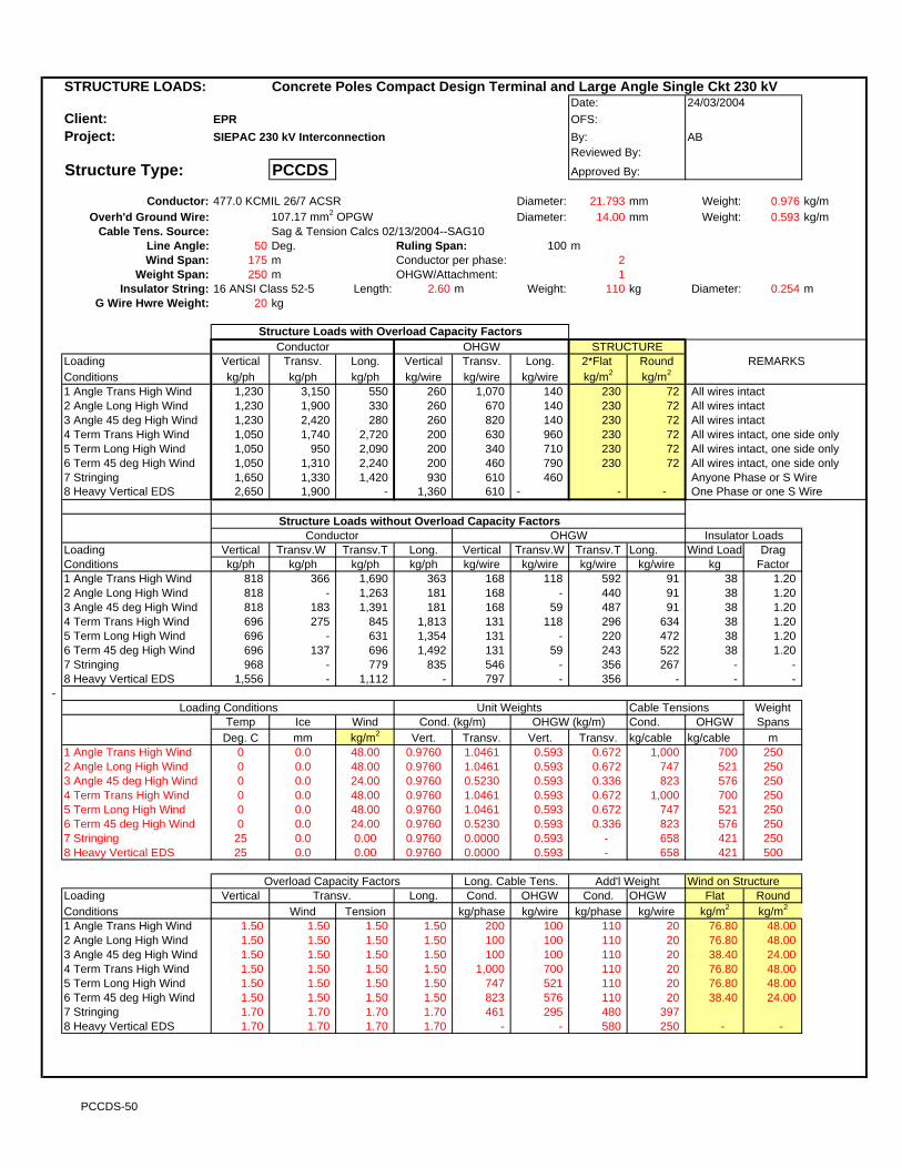
STRUCTURE LOADS: Concrete Poles Compact Design Terminal and Large Angle Single Ckt 230 kVDate:
Client: EPR OFS:Project: SIEPAC 230 kV Interconnection By: AB
Reviewed By:
Structure Type: PCCDS Approved By:
Conductor: 477.0 KCMIL 26/7 ACSR Diameter: 21.793 mm Weight: 0.976 kg/mOverh'd Ground Wire: 107.17 mm2 OPGW Diameter: 14.00 mm Weight: 0.593 kg/m
Cable Tens. Source: Sag & Tension Calcs 02/13/2004--SAG10Line Angle: 50 Deg. Ruling Span: 100 mWind Span: 175 m Conductor per phase: 2
Weight Span: 250 m OHGW/Attachment: 1Insulator String: 16 ANSI Class 52-5 Length: 2.60 m Weight: 110 kg Diameter: 0.254 m
G Wire Hwre Weight: 20 kg
Structure Loads with Overload Capacity FactorsConductor OHGW
Loading Vertical Transv. Long. Vertical Transv. Long. 2*Flat RoundConditions kg/ph kg/ph kg/ph kg/wire kg/wire kg/wire kg/m2 kg/m2
1 Angle Trans High Wind 1,230 3,150 550 260 1,070 140 230 72 All wires intact2 Angle Long High Wind 1,230 1,900 330 260 670 140 230 72 All wires intact3 Angle 45 deg High Wind 1,230 2,420 280 260 820 140 230 72 All wires intact4 Term Trans High Wind 1,050 1,740 2,720 200 630 960 230 72 All wires intact, one side only5 Term Long High Wind 1,050 950 2,090 200 340 710 230 72 All wires intact, one side only6 Term 45 deg High Wind 1,050 1,310 2,240 200 460 790 230 72 All wires intact, one side only7 Stringing 1,650 1,330 1,420 930 610 460 Anyone Phase or S Wire8 Heavy Vertical EDS 2,650 1,900 - 1,360 610 - - - One Phase or one S Wire
Structure Loads without Overload Capacity Factors
Loading Vertical Transv.W Transv.T Long. Vertical Transv.W Transv.T Long. Wind Load DragConditions kg/ph kg/ph kg/ph kg/ph kg/wire kg/wire kg/wire kg/wire kg Factor1 Angle Trans High Wind 818 366 1,690 363 168 118 592 91 38 1.202 Angle Long High Wind 818 - 1,263 181 168 - 440 91 38 1.203 Angle 45 deg High Wind 818 183 1,391 181 168 59 487 91 38 1.20 4 Term Trans High Wind 696 275 845 1,813 131 118 296 634 38 1.20 5 Term Long High Wind 696 - 631 1,354 131 - 220 472 38 1.20 6 Term 45 deg High Wind 696 137 696 1,492 131 59 243 522 38 1.20 7 Stringing 968 - 779 835 546 - 356 267 - -8 Heavy Vertical EDS 1,556 - 1,112 - 797 - 356 - - -
- Loading Conditions Unit Weights Cable Tensions Weight
Temp Ice Wind Cond. (kg/m) OHGW (kg/m) Cond. OHGW SpansDeg. C mm kg/m2 Vert. Transv. Vert. Transv. kg/cable kg/cable m
1 Angle Trans High Wind 0 0.0 48.00 0.9760 1.0461 0.593 0.672 1,000 700 2502 Angle Long High Wind 0 0.0 48.00 0.9760 1.0461 0.593 0.672 747 521 2503 Angle 45 deg High Wind 0 0.0 24.00 0.9760 0.5230 0.593 0.336 823 576 2504 Term Trans High Wind 0 0.0 48.00 0.9760 1.0461 0.593 0.672 1,000 700 2505 Term Long High Wind 0 0.0 48.00 0.9760 1.0461 0.593 0.672 747 521 2506 Term 45 deg High Wind 0 0.0 24.00 0.9760 0.5230 0.593 0.336 823 576 2507 Stringing 25 0.0 0.00 0.9760 0.0000 0.593 - 658 421 2508 Heavy Vertical EDS 25 0.0 0.00 0.9760 0.0000 0.593 - 658 421 500
Overload Capacity Factors Long. Cable Tens. Add'l Weight Wind on StructureLoading Vertical Transv. Long. Cond. OHGW Cond. OHGW Flat RoundConditions Wind Tension kg/phase kg/wire kg/phase kg/wire kg/m2 kg/m2
1 Angle Trans High Wind 1.50 1.50 1.50 1.50 200 100 110 20 76.80 48.00 2 Angle Long High Wind 1.50 1.50 1.50 1.50 100 100 110 20 76.80 48.00 3 Angle 45 deg High Wind 1.50 1.50 1.50 1.50 100 100 110 20 38.40 24.00 4 Term Trans High Wind 1.50 1.50 1.50 1.50 1,000 700 110 20 76.80 48.00 5 Term Long High Wind 1.50 1.50 1.50 1.50 747 521 110 20 76.80 48.00 6 Term 45 deg High Wind 1.50 1.50 1.50 1.50 823 576 110 20 38.40 24.00 7 Stringing 1.70 1.70 1.70 1.70 461 295 480 397 8 Heavy Vertical EDS 1.70 1.70 1.70 1.70 - - 580 250 - -
Conductor OHGW
24/03/2004
REMARKS
Insulator Loads
STRUCTURE
PCCDS-50

STRUCTURE LOADS: Concrete Poles Compact Design Terminal and Large Angle Single Ckt 230 kVDate:
Client: EPR OFS:Project: SIEPAC 230 kV Interconnection By: AB
Reviewed By:
Structure Type: PCCDS Approved By:
Conductor: 477.0 KCMIL 26/7 ACSR Diameter: 21.793 mm Weight: 0.976 kg/mOverh'd Ground Wire: 107.17 mm2 OPGW Diameter: 14.00 mm Weight: 0.593 kg/m
Cable Tens. Source: Sag & Tension Calcs 02/13/2004--SAG10Line Angle: 50 Deg. Ruling Span: 100 mWind Span: 175 m Conductor per phase: 2
Weight Span: -150 m OHGW/Attachment: 1Insulator String: 16 ANSI Class 52-5 Length: 2.60 m Weight: 110 kg Diameter: 0.254 m
G Wire Hwre Weight: 20 kg
Structure Loads with Overload Capacity FactorsConductor OHGW
Loading Vertical Transv. Long. Vertical Transv. Long. 2*Flat RoundConditions kg/ph kg/ph kg/ph kg/wire kg/wire kg/wire kg/m2 kg/m2
1 Angle Trans High Wind 60 3,150 550 (110) 1,070 140 230 72 All wires intact2 Angle Long High Wind 60 1,900 330 (110) 670 140 230 72 All wires intact3 Angle 45 deg High Wind 60 2,420 280 (110) 820 140 230 72 All wires intact4 Term Trans High Wind 170 1,740 2,720 (80) 630 960 230 72 All wires intact, one side only5 Term Long High Wind 170 950 2,090 (80) 340 710 230 72 All wires intact, one side only6 Term 45 deg High Wind 170 1,310 2,240 (80) 460 790 230 72 All wires intact, one side only7 Stringing 320 1,330 1,420 530 610 460 Anyone Phase or S Wire8 Heavy Vertical EDS 2,650 1,900 - 1,360 610 - - - One Phase or one S Wire
Structure Loads without Overload Capacity Factors
Loading Vertical Transv.W Transv.T Long. Vertical Transv.W Transv.T Long. Wind Load DragConditions kg/ph kg/ph kg/ph kg/ph kg/wire kg/wire kg/wire kg/wire kg Factor1 Angle Trans High Wind 37 366 1,690 363 (69) 118 592 91 38 1.202 Angle Long High Wind 37 - 1,263 181 (69) - 440 91 38 1.203 Angle 45 deg High Wind 37 183 1,391 181 (69) 59 487 91 38 1.20 4 Term Trans High Wind 110 275 845 1,813 (47) 118 296 634 38 1.20 5 Term Long High Wind 110 - 631 1,354 (47) - 220 472 38 1.20 6 Term 45 deg High Wind 110 137 696 1,492 (47) 59 243 522 38 1.20 7 Stringing 188 - 779 835 308 - 356 267 - -8 Heavy Vertical EDS 1,556 - 1,112 - 797 - 356 - - -
- Loading Conditions Unit Weights Cable Tensions Weight
Temp Ice Wind Cond. (kg/m) OHGW (kg/m) Cond. OHGW SpansDeg. C mm kg/m2 Vert. Transv. Vert. Transv. kg/cable kg/cable m
1 Angle Trans High Wind 0 0.0 48.00 0.9760 1.0461 0.593 0.672 1,000 700 -1502 Angle Long High Wind 0 0.0 48.00 0.9760 1.0461 0.593 0.672 747 521 -1503 Angle 45 deg High Wind 0 0.0 24.00 0.9760 0.5230 0.593 0.336 823 576 -1504 Term Trans High Wind 0 0.0 48.00 0.9760 1.0461 0.593 0.672 1,000 700 -1505 Term Long High Wind 0 0.0 48.00 0.9760 1.0461 0.593 0.672 747 521 -1506 Term 45 deg High Wind 0 0.0 24.00 0.9760 0.5230 0.593 0.336 823 576 -1507 Stringing 25 0.0 0.00 0.9760 0.0000 0.593 - 658 421 -1508 Heavy Vertical EDS 25 0.0 0.00 0.9760 0.0000 0.593 - 658 421 500
Overload Capacity Factors Long. Cable Tens. Add'l Weight Wind on StructureLoading Vertical Transv. Long. Cond. OHGW Cond. OHGW Flat RoundConditions Wind Tension kg/phase kg/wire kg/phase kg/wire kg/m2 kg/m2
1 Angle Trans High Wind 1.50 1.50 1.50 1.50 200 100 110 20 76.80 48.00 2 Angle Long High Wind 1.50 1.50 1.50 1.50 100 100 110 20 76.80 48.00 3 Angle 45 deg High Wind 1.50 1.50 1.50 1.50 100 100 110 20 38.40 24.00 4 Term Trans High Wind 1.50 1.50 1.50 1.50 1,000 700 110 20 76.80 48.00 5 Term Long High Wind 1.50 1.50 1.50 1.50 747 521 110 20 76.80 48.00 6 Term 45 deg High Wind 1.50 1.50 1.50 1.50 823 576 110 20 38.40 24.00 7 Stringing 1.70 1.70 1.70 1.70 461 295 480 397 8 Heavy Vertical EDS 1.70 1.70 1.70 1.70 - - 580 250 - -
Conductor OHGW
24/03/2004
REMARKS
Insulator Loads
STRUCTURE
PCCDS-50-Uplift

STRUCTURE LOADS: Concrete Poles Compact Design Terminal and Large Angle Single Ckt 230 kVDate:
Client: EPR OFS:Project: SIEPAC 230 kV Interconnection By: AB
Reviewed By:
Structure Type: PCCDS Approved By:
Conductor: 477.0 KCMIL 26/7 ACSR Diameter: 21.793 mm Weight: 0.976 kg/mOverh'd Ground Wire: 107.17 mm2 OPGW Diameter: 14.00 mm Weight: 0.593 kg/m
Cable Tens. Source: Sag & Tension Calcs 02/13/2004--SAG10Line Angle: 0 Deg. Ruling Span: 100 mWind Span: 175 m Conductor per phase: 2
Weight Span: -150 m OHGW/Attachment: 1Insulator String: 16 ANSI Class 52-5 Length: 2.60 m Weight: 110 kg Diameter: 0.254 m
G Wire Hwre Weight: 20 kg
Structure Loads with Overload Capacity FactorsConductor OHGW
Loading Vertical Transv. Long. Vertical Transv. Long. 2*Flat RoundConditions kg/ph kg/ph kg/ph kg/wire kg/wire kg/wire kg/m2 kg/m2
1 Angle Trans High Wind 60 610 600 (110) 180 150 230 72 All wires intact2 Angle Long High Wind 60 - 360 (110) - 150 230 72 All wires intact3 Angle 45 deg High Wind 60 340 300 (110) 90 150 230 72 All wires intact4 Term Trans High Wind 170 470 3,000 (80) 180 1,050 230 72 All wires intact, one side only5 Term Long High Wind 170 - 2,300 (80) - 790 230 72 All wires intact, one side only6 Term 45 deg High Wind 170 270 2,470 (80) 90 870 230 72 All wires intact, one side only7 Stringing 1,650 - 1,570 930 - 510 Anyone Phase or S Wire8 Heavy Vertical EDS 2,650 - - 1,360 - - - - One Phase or one S Wire
Structure Loads without Overload Capacity Factors
Loading Vertical Transv.W Transv.T Long. Vertical Transv.W Transv.T Long. Wind Load DragConditions kg/ph kg/ph kg/ph kg/ph kg/wire kg/wire kg/wire kg/wire kg Factor1 Angle Trans High Wind 37 366 - 400 (69) 118 - 100 38 1.202 Angle Long High Wind 37 - - 200 (69) - - 100 38 1.203 Angle 45 deg High Wind 37 183 - 200 (69) 59 - 100 38 1.20 4 Term Trans High Wind 110 275 - 2,000 (47) 118 - 700 38 1.20 5 Term Long High Wind 110 - - 1,494 (47) - - 521 38 1.20 6 Term 45 deg High Wind 110 137 - 1,646 (47) 59 - 576 38 1.20 7 Stringing 968 - - 921 546 - - 295 - -8 Heavy Vertical EDS 1,556 - - - 797 - - - - -
- Loading Conditions Unit Weights Cable Tensions Weight
Temp Ice Wind Cond. (kg/m) OHGW (kg/m) Cond. OHGW SpansDeg. C mm kg/m2 Vert. Transv. Vert. Transv. kg/cable kg/cable m
1 Angle Trans High Wind 0 0.0 48.00 0.9760 1.0461 0.593 0.672 1,000 700 -1502 Angle Long High Wind 0 0.0 48.00 0.9760 1.0461 0.593 0.672 747 521 -1503 Angle 45 deg High Wind 0 0.0 24.00 0.9760 0.5230 0.593 0.336 823 576 -1504 Term Trans High Wind 0 0.0 48.00 0.9760 1.0461 0.593 0.672 1,000 700 -1505 Term Long High Wind 0 0.0 48.00 0.9760 1.0461 0.593 0.672 747 521 -1506 Term 45 deg High Wind 0 0.0 24.00 0.9760 0.5230 0.593 0.336 823 576 -1507 Stringing 25 0.0 0.00 0.9760 0.0000 0.593 - 658 421 2508 Heavy Vertical EDS 25 0.0 0.00 0.9760 0.0000 0.593 - 658 421 500
Overload Capacity Factors Long. Cable Tens. Add'l Weight Wind on StructureLoading Vertical Transv. Long. Cond. OHGW Cond. OHGW Flat RoundConditions Wind Tension kg/phase kg/wire kg/phase kg/wire kg/m2 kg/m2
1 Angle Trans High Wind 1.50 1.50 1.50 1.50 200 100 110 20 76.80 48.00 2 Angle Long High Wind 1.50 1.50 1.50 1.50 100 100 110 20 76.80 48.00 3 Angle 45 deg High Wind 1.50 1.50 1.50 1.50 100 100 110 20 38.40 24.00 4 Term Trans High Wind 1.50 1.50 1.50 1.50 1,000 700 110 20 76.80 48.00 5 Term Long High Wind 1.50 1.50 1.50 1.50 747 521 110 20 76.80 48.00 6 Term 45 deg High Wind 1.50 1.50 1.50 1.50 823 576 110 20 38.40 24.00 7 Stringing 1.70 1.70 1.70 1.70 461 295 480 397 8 Heavy Vertical EDS 1.70 1.70 1.70 1.70 - - 580 250 - -
Conductor OHGW
24/03/2004
REMARKS
Insulator Loads
STRUCTURE
PCCDS-0