
Emmanuel Nyameke FEASIBILITY STUDY OF IMPLEMENTING AN ...
54
i Emmanuel Nyameke FEASIBILITY STUDY OF IMPLEMENTING AN INDUSTRIAL ROBOT FOR INDUCTION HARDENING MACHINE Technology and Communication 2013
Transcript of Emmanuel Nyameke FEASIBILITY STUDY OF IMPLEMENTING AN ...

i
Emmanuel Nyameke
FEASIBILITY STUDY OF
IMPLEMENTING AN INDUSTRIAL
ROBOT FOR INDUCTION
HARDENING MACHINE
Technology and Communication
2013

ACKNOWLEDGMENTS
My acknowledgment does go to the Lord God Almighty for seeing me through
this thesis and also giving me the insight and strength to undergo this study. I
would like to express my sincere gratitude to my supervisor Dr. Adebayo
Agbejule for the guidance and support throughout the entire time of my thesis
work and my study at Vaasa University of Applied sciences. He has been very
helpful in helping me to get the right literature and creating a good atmosphere
that made it possible to complete this thesis successfully, he has really been a
blessing to me. I also thank all the lecturers in the Mechanical Department of
VAMK University of Applied Sciences for their knowledge impacted in me and
not forgetting mechanical HOD Lota for her support and care.
I also acknowledge the very effort of Mr. Veli-Pekka Nurminen the plant manager
of Bodycote Lämpökäsittely Oy for his directions, time and support throughout
this study and also giving me the opportunity to work on this research for his
company.
Finally I thank my family and friends for their support and motivations during this
time of the thesis, I really appreciate all. God bless you.

VAASAN AMMATTIKORKEAKOULU
UNIVERSITY OF APPLIED SCIENCES
Degree Programme in Mechanical and Production Engineering
ABSTRACT
Author Emmanuel Nyameke
Title Feasibility Study of Implementing an Industrial Robot
For Induction Hardening Machine
Year 2013
Language English
Pages 54
Name of Supervisor Adebayo Agbejule
The objective of the thesis was to make a feasibility study of implementing an
industrial robot for the induction hardening machine.
Various industrial robots were studied and compared in the thesis to find a
suitable robot. A cost analysis of using a human and the robot for that task and the
practical demonstration of the appropriate industrial robot which is suitable for
induction hardening were also made. Finally, articulated robot was chosen due to
its good working area and enough working axis.
In this study qualitative research method was used. In-depth interview and
participant observation process were employed in achieving the results. The result
of the cost analysis between the human operator and the robot to run the induction
machine showed witness that the use of the robot increases production and is more
profitable.

CONTENTS
ABSTRACT
1 INTRODUCTION ............................................................................................... 1
1.1 Main objective ............................................................................................ 1
1.2 Secondary objective .................................................................................... 2
1.3 Research questions ..................................................................................... 2
2 THEORETICAL BACKGROUND ................................................................. 3
2. 1 Heat treatment ........................................................................................... 3
2.2 Types of heat treatment process ................................................................. 3
2.2.1 Hardening ................................................................................................ 3
2.2.2 Tempering ................................................................................................ 4
2.2.3 Annealing ................................................................................................ 4
2.2.4 Normalizing ............................................................................................. 4
2.3 Induction heating ........................................................................................ 5
2.3.1 Induction coils ......................................................................................... 8
3 INDUSTRIAL ROBOTS ............................................................................... 10
3.1 History of industrial robots ....................................................................... 10
3.2 Characteristic of industrial robots ............................................................ 11
3.2.1 Sensing .................................................................................................. 11
3.2.2 Movement .............................................................................................. 12
3.2.3 Energy .................................................................................................... 12
3.2.4 Intelligence ............................................................................................ 12
3.3 Types of industrial robot .......................................................................... 12
3.3.1 Industrial robotics .................................................................................. 13
3.3.2 Cartesian robot ....................................................................................... 13
3.3.3 SCARA robot ........................................................................................ 14
3.3.4 Articulated robot .................................................................................... 15
3.3.5 Parallel or Delta robot ........................................................................... 16
3.3.6 Cylindrical robot .................................................................................... 17
3.3.7 Polar robot ............................................................................................. 18
3.4 Components of industrial robots .............................................................. 19
3.4.1 The robotic arm ..................................................................................... 19
3.4.2 The robotic controller ............................................................................ 20

3.4.3 Robotic drives ........................................................................................ 20
3.4.4 Robotic end effectors ............................................................................. 20
3.4.5 Robotic sensors ...................................................................................... 20
3.5 Reasons for using or investing in industrial robot .................................... 21
4 RESEARCH METHODOLOGIES .................................................................. 22
4.1 Research ................................................................................................... 22
4.2 Types of research methods ....................................................................... 23
4.2.1Quantitatve research method .................................................................. 23
4.2.2 Qualitative research method .................................................................. 23
4.2.3 Mixed Research method ........................................................................ 24
5 CASE COMPANY (BODYCOTE) ................................................................... 26
5.1 Bodycote Vaasa plant ............................................................................... 27
5.2 Main processes carried out in Vaasa plant ............................................... 27
5.2.1 Carburizing ............................................................................................ 28
5.2.2 Case hardening ...................................................................................... 28
5.2.3 Nitriding ................................................................................................ 28
5.2.4 Nitrocarburising ..................................................................................... 29
5.2.5 Induction hardening ............................................................................... 29
5.3 Proposed robot to be used ......................................................................... 31
6 COST ANALYSIS ......................................................................................... 35
6.1 Number of work pieces ............................................................................ 35
6.1.2 A breakdown of the total cost of the robot ............................................ 36
6. 1.3 The cost analysis for using robot .......................................................... 38
6.1.4 The cost analysis for running the induction machine by human ........... 39
7 CONCLUSIONS ............................................................................................ 41
7.1 Limitations ................................................................................................ 41
7.1.1 Recommendation ................................................................................... 42
REFERENCES ...................................................................................................... 43
APPENDIX .......................................................................................................... 46

LIST OF FIGURES
Figure 1 A basic induction heating setup. .............................................................. 6
Figure 2 Eddy currents flowing against the electrical resistivity of the metal. ..... 7
Figure 3 Using induction heat method to harden a specific metal part. .................. 8
Figure 4 Induction heating coil design. .................................................................. 9
Figure 5 Unimate’s first industrial robot. .............................................................. 11
Figure 6 Cartesian robot and its working area ..................................................... 14
Figure 7 . SCARA robot and its working area. .................................................... 15
Figure 8 Articulated robot and its working area. ................................................. 16
Figure 9 A parallel robot and its working area. ................................................... 17
Figure 10 Cylindrical robot and its working area ................................................ 18
Figure 11 The working principles of the polar robot (coordinate system) .......... 18
Figure 12 Polar robot and its working area .......................................................... 19
Figure 13. The big and small induction hardening machine at Bodycote Vaasa. 30
Figure 14 The front view of the small induction machine. ................................... 31
Figure 15 The side view of the small induction machine ................................... 31
Figure 16 6kg articulated robot. ........................................................................... 32
Figure 17. Application of articulated robot ........................................................... 33
Figure 18. Current arrangement in the process of the induction hardening. ......... 34
Figure 19. Breakeven analysis graph for using the robot for induction hardening.
............................................................................................................................... 39
Figure 20. The breakeven analysis graph of using the induction machine by a
human operator...................................................................................................... 40

LIST OF TABLES
Table 1 Work piece A……………………………………………………..…37
Table 2 Work piece B……………..…………………………………………38
Table 3 Work piece C……………………………………………..………...38
Table 4 The total cost of installing the robot………………….…………….39
Table 5 Total work pieces with different heating and handling time………40
Table 6 Cost analysis for using robot……………………………………….41
Table 7 Cost analysis by using human…….………………………………..42

1
1 INTRODUCTION
The main objective of every thesis was to build up a theory or to test a theory that
has already been built and the main objective for this thesis was to estimate the
costs analyses of implementing industrial robot for the small induction machine at
Bodycote, Vaasa.
Bodycote has been in the heat treatment industry ever since the year 1648 and
currently the world’s leading specialist in testing and thermal processing services.
It is a provider of heat treatment, hot iso-static pressing, metallurgical coating and
testing services to many manufacturing companies.
The small induction hardening machine at Bodycote Vaasa is mostly used for
induction hardening of small components, the number of the these components
can be about 5000 pieces and it require a lot of time to harden all these
components.
The induction hardening section at Bodycote Vaasa is run by one shift which is
approximately eight hours (8h). Due to this a delay in delivery time when a
numerous amount of a particular component are to be treated. Therefore. this
research considers the cost analyses of implementing an industrial robot to be run
after the day activities and determine how it will help the management.
There are two induction hardening machines at Bodycote Vaasa: the big one for
large components and the small one for small components. This research focuses
on the small induction hardening machine
1.1 Main Objective
The main objective of this research was to estimate the total cost of implementing
an industrial robot for the small induction hardening machine at Bodycote,
Vaasa.

2
1.2 Secondary objective
The secondary objective was to come out with a clear decision based on the costs
analyses, if the implementation of robot for the induction machine will lead to
profit.
1.3 Research questions
Based on the discussion with experts about the issues involving in implementing
an industrial robot, the following research questions have been defined:
1. How profitable will it be to implement an industrial robot for the small
induction hardening machine at Bodycote, Vaasa?
2. How can the robot increase the time of delivery at Bodycote Vaasa?
3. How will the robot affect the working environment at Bodycote Vaasa?

3
2 THEORETICAL BACKGROUND
The theoretical background for the thesis is given next.
2. 1 Heat treatment
Heat treatment is mostly done with idea of increasing the physical strength of the
material, but it can also lead in offering certain properties of materials that helps
to achieve good manufacturing procedure, such as improving machinability,
improve formability and restoring of ductility after a cold working operation. Heat
treatment process has a vital role to play on the product aside improving the
manufacturing processes it also boost the product performances by increasing
toughness, strength or other desirable characteristics. /14/
The properties of a material can be changed by undergoing heat treatment process.
Such properties can be the hardness, toughness, malleability, ductility, micro-
structure and stress concentration. The type of property needed will determine the
type of heat treatment process to be used. /35/
2.2 Types of heat treatment process
In order to obtain the right properties for a material or a component by heat
treatment process, there are various types of heat treatment processes that are used
to achieve these properties. Depending on the property require the material can
undergo more than one heat treatment process. The following are heat treatment
processes or methods being used for engineering materials:
2.2.1 Hardening
This is the process of heating steel just above its upper critical temperature or
keeping it at an appropriate temperature until all partite is transformed into
austenite, and then quenching it rapidly in water or oil. The carbon content of the
steel determines the temperature at which austentizing will take place. /8/

4
The main reason of hardening is to increase the hardness of the work piece as
possible. The hardness of the steel depends mostly on its hardenability and the
amount of carbon it contains, the size of the material and the condition during the
heat treatment process also has a little to do with the hardness. /32/
2.2.2 Tempering
This is the heat treatment method that is applied to a material which has been
already hardened to optimize its ductility, toughness and reduce its brittleness.
After hardening steel it becomes very hard and brittle, therefore tempering is
carried out to relieve the brittleness or stresses in the martensite structure. The
tempering process is carried out by heating the hardened material below its critical
temperature (350 to 400 ºC) and then cooled slowly to allow the carbon to diffuse
out of the body-centered tetragonal structure, in that optimizing its ductile and
stable body-centered structure./21/
2.2.3 Annealing
This process is carried out to reduce hardness, remove residual stresses,
optimizing toughness and re-gaining the ductility of a metal. It provides
mechanical, electrical or magnetic properties for the material via the refinement of
the grain structure. The process is carried out by heating the material just above its
critical temperature or above austenitic phase and then cooled very slowly. During
this process oxidation is carried out due to controlling the atmosphere by insert
gas. /19/
2.2.4 Normalizing
After a material has undergone a manufacturing process such as wedding or
forging the material grain structure become distorted. Therefore the normalizing
process is carried out to refine the grain structure of the material thereby avoiding
excessive softness in the material as well. The material is then heated just above
its critical temperature (1100 ºC) and cooled in air. /19/

5
2.3 Induction heating
To stay competitive in today’s market place, production effective and cost
effectiveness are essential. Among the various sources of heat treatment methods
in today manufacturing process (flame, oven, resistance and induction), induction
heating is increasingly attractive option. Flame heating techniques produces a
hard working environment with poor temperature control and requires a high level
of operation skill; traditionally other heating system (oven) requires a huge
investment and valuable floor space and must be continuously operated to avoid
long steps of delays and resistance heating surfers from poor repeatability and
unreliable content resistance./39/
Induction heating overcomes all the aforementioned sources of heat limitations,
traditionally described as a quick none contact material heating method. Induction
heating utilizes the unique properties of radio frequency energy, the area of
spectrum below infrared and microwave. In a typical induction system RF power
supply sends alternative current through a couple of coils generating a magnetic
field. When the part (work piece) is placed in the coil circulating eddy current
induce within the part flow against the electrical resistibility of the material and
generate heat. Figure 1 shows a basic setup of induction heating. /39/

6
Figure 1. A basic induction heating setup. /18/
Figure 2 shows how these eddy currents flow against the electrical resistivity of
the metal, generating precise and localized heat without any direct contact
between the part and the inductor. The heating occurs with both magnetic and
non-magnetic parts, referring the scientific formula known as Joules effect which
expresses the relationship between heats produced by electrical current passed
through a conductor. It is expressed as "Q = I2 x R x t" where Q is the amount of
heat produced, I is the current flowing through the part (conductor), R is the
electrical resistance of the part, and t = time”. (39, 17)
In the process of heating the material, there is therefore no contact between the
inductor and the part, and neither are there any combustion gases. The material to
be heated can be located in a setting isolated from the power supply; submerged in
a liquid, covered by isolated substances, in gaseous atmospheres or even in a
vacuum. /39/

7
Figure 2. Eddy currents flowing against the electrical resistivity of the metal. /18/
Although induction is based on a well-known principle it is continuously being
rediscovered because of the unique adventures. First and foremost induction is
best, temperature about 1100 ºC can be produced in a second, induction is highly
controllable and very selective, the exact amount of heat needed can be delivered
precisely and exactly where needed without affecting surrounding areas or
environment as shown in Figure 3. /39/

8
Figure 3. Using induction heat method to harden a specific metal part. /39/
2.3.1 Induction coils
An induction coil which is also called inductor, plays a very important role in the
induction heating processes. The effect of the heating process mainly bases on the
effectiveness of the coil, therefore the coil should be carefully or properly made, a
quality material should be used. The coil should be maintained correctly and there
should be the correct amount of power to achieve good induction heating process
with high efficiency. /13/
Induction coils hold the whole installation of the induction heating process,
therefore, it must be able to meet some standard requirements. Such requirements
are a satisfactory or long life span, desirable production rate, a good conductivity
of electricity, and the ability to stand the heat with less change in the part
dimension. /15/
Induction coils differ from each other depending on the design, geometry,
dimension and the material used to make it. The design or the number of coils
depends on the nature of component to be heat treated. Figure 4 shows some
different types of induction heating coils. /15/

9
Figure 4. Induction heating coil design. /9/

10
3 INDUSTRIAL ROBOTS
3.1 History of industrial robots
The word “Robot” was first introduced in 1920 by two Czech brothers Karel
Capek and Josef Capek. Karel was a Czech writer who found it difficult or
unpleasant to use the word laboři for his man-made creatures in a play. Then his
brother Josef presented the Latin word roboti which means self-labor. The word
was later coined to robotic by a science writer called Isaac Asimov when he
decided to expand on that in 1944. /30/
Ever since man started thinking about machines the perception of human-like
robot has been existence for hundreds of years. Engineers and science writers
have elaborated on that till 1956 when Devol and Joe Engelberger, established a
company with the name Unimation which was a shortened word from the two
words Universal Animation. /27/
Devol and Engelberger came out with a brilliant idea derived the first industrial
robot in 1959. Figure 5 showe the first industrial robot which was called
Unimate; in 1967 Unimation installed the first industrial robot in Europe at
Metallverken, Uppsland Väsby, Sweden. /27/
11
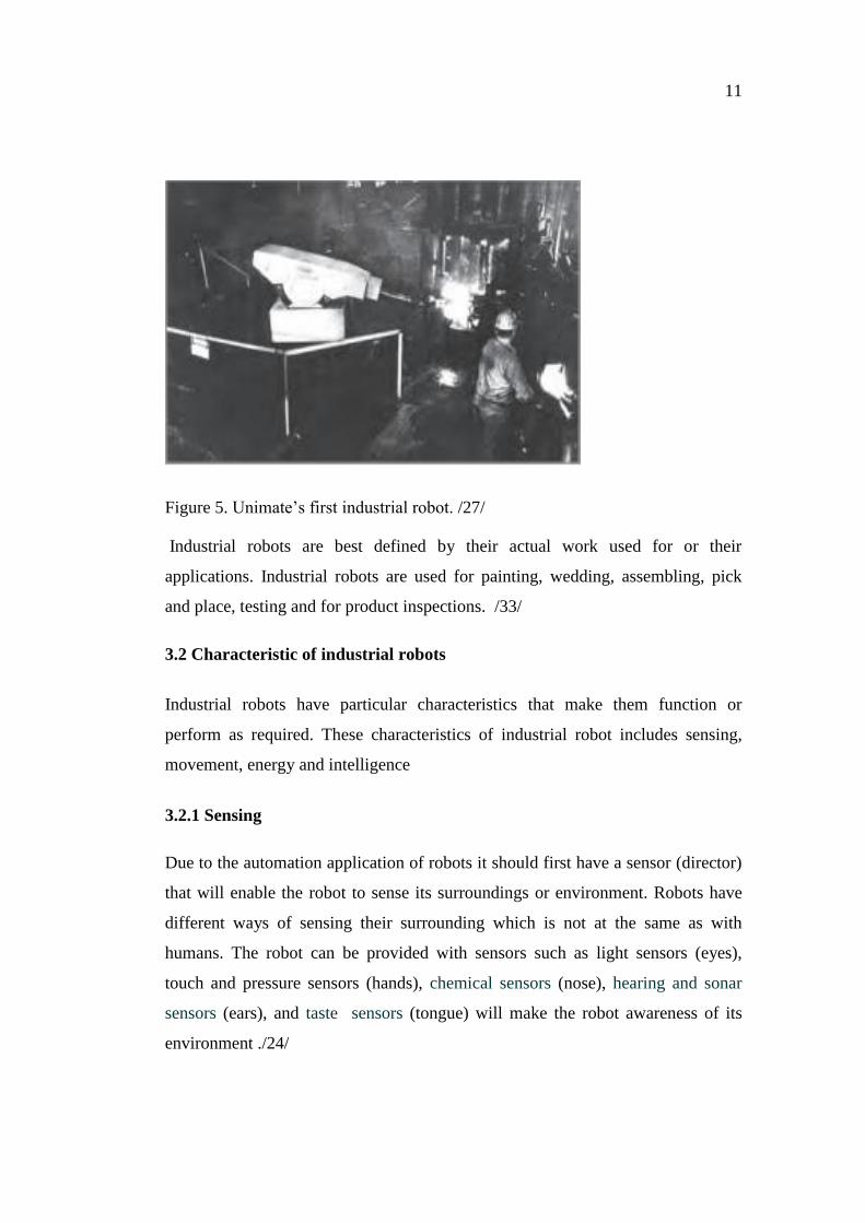
Figure 5. Unimate’s first industrial robot. /27/
Industrial robots are best defined by their actual work used for or their
applications. Industrial robots are used for painting, wedding, assembling, pick
and place, testing and for product inspections. /33/
3.2 Characteristic of industrial robots
Industrial robots have particular characteristics that make them function or
perform as required. These characteristics of industrial robot includes sensing,
movement, energy and intelligence
3.2.1 Sensing
Due to the automation application of robots it should first have a sensor (director)
that will enable the robot to sense its surroundings or environment. Robots have
different ways of sensing their surrounding which is not at the same as with
humans. The robot can be provided with sensors such as light sensors (eyes),
touch and pressure sensors (hands), chemical sensors (nose), hearing and sonar
sensors (ears), and taste sensors (tongue) will make the robot awareness of its
environment ./24/
12
3.2.2 Movement
One of the characteristics required in a machine as a robot is that it should be able
to move within its working environment or premises. This movement can be
rolling on wheels, walking on legs or propelling by thrusters. /24/
3.2.3 Energy
The energy used by the robot is counted as one of its important characteristics as
the robot needs to be able to power itself. There are different ways it can be
powered: robot might be solar powered, electrically powered, battery powered or
hydraulically powered. The work of which the robot is designed to do or its
function will determine the type of energy source to be used to power the robot.
/24/
3.2.4 Intelligence
The most important among all the characteristics of robots is its intelligence. This
is the area where programming enters into the scene. The robot is smart when it
does exactly what it is supposed to do. The programmer then is a person who is to
provide the robot its smartness. The robot therefore receives the program to
determine what to do, when to do and how to do it. /28/
3.3 Types of industrial robot
There are various types of industrial robots and they are in different shape and
size mostly based on their moving mechanism. They are designed to operate in a
way that will help everyday manufacturing lives. The moving axes of the robot
determines its mechanism and the ability of its movement is based on the number
and arrangement of the moving axes. /25/
Industrial robots have different application and specifications, depending on the
type of the industrial robot. There are different robotic configurations as well.
Non-servo robots, servo robots, programmable robots and computer
13
programmable robots are some basic types of industrial robots commonly used.
/36/
A non-servo robot is mostly used to transport objects from one place to another. It
does that by moving the object to a specified place after picking and then drops it.
/36/
A servo robot has an amount of manipulators and effectors which makes is able to
feature in a wider range. Servo robots have robotic outgrowths which make it
function as the robot arms and hands, makes it flexible or boosting its flexibility
and greater movement. /36/
A programmable robot has the capability of storing commands in a database
which makes it to repeat the task given as much as required. A computer
programmable robot is equally a servo robot that uses a computer to control
through distance. /36/
3.3.1 Industrial robotics
Industrial robots are configured based on their movement and capabilities. There
are different types of industrial robots used for industrial applications; industrial
robots are mainly group in six different types which are Cartesian robot, SCARA
robot, articulated robot, parallel robots, cylindrical robot and polar robot. /30/
3.3.2 Cartesian robot
The Cartesian robot due to its structure and design has different types of names
such as linear robots or gantry robots. The kinematics of a Cartesian robot is of
three axes (XYZ) and has some similarities with the milling machine. Cartesian
robots are mounted on a linear track supported by a pillar around the working
area. The design and structure of the robot makes it possible for large geometrical
work to be easily handled. Cartesian robots are suitable used for palletizing and
handling work, they are sometimes combined with articulated robots for a good

14
combined kinematics. Figure 6 shows a Cartesian robot and its working area. /25,
/30/.
Figure 6. Cartesian robot and its working area /25/, /11/
3.3.3 SCARA robot
The name SCARA is an acronym which stands for: Selected Compliant Assembly
Robot Arm. In some cases it is also referred to as Selected Compliant Articulated
Robot Arm. A SCARA robot has a cylindrical working environment or work
envelope as the same as that of the cylindrical robot but it has round ends as
shown in Figure 7. It is mainly used for precision work within one plane; SCARA
robots have two rotational joints with high horizontal stiffness. It has three axes
(XYZ) which it can move within its working environment. They are used for pick
and place applications but are very expensive due to their controlling software
which requires inverse kinematics for linear interpolated movement. /25/, /30/,
/27/
15
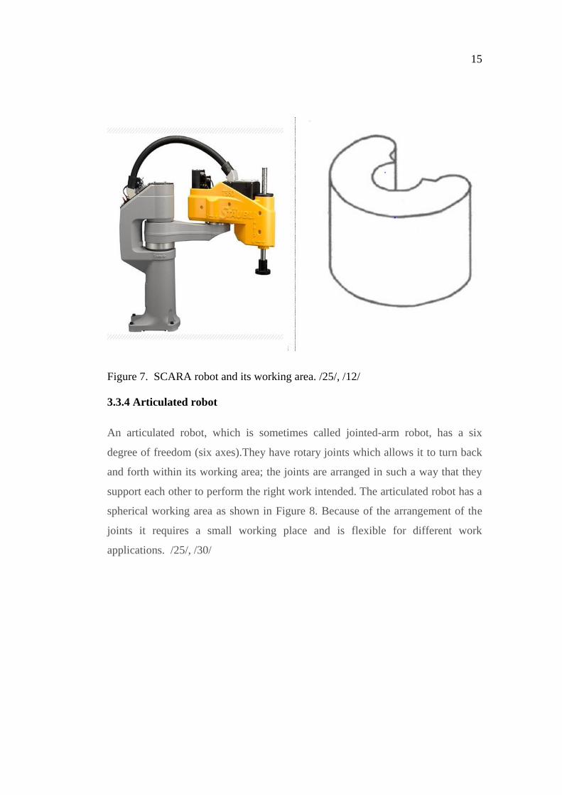
Figure 7. SCARA robot and its working area. /25/, /12/
3.3.4 Articulated robot
An articulated robot, which is sometimes called jointed-arm robot, has a six
degree of freedom (six axes).They have rotary joints which allows it to turn back
and forth within its working area; the joints are arranged in such a way that they
support each other to perform the right work intended. The articulated robot has a
spherical working area as shown in Figure 8. Because of the arrangement of the
joints it requires a small working place and is flexible for different work
applications. /25/, /30/

16
Figure 8. Articulated robot and its working area. /25/, /26/
3.3.5 Parallel or Delta robot
A Delta robot which is also called a parallel robot has a great many different
applications as compared to the other robot configurations. Its configuration is a
combination of rotational axes and parallelograms; it has a constrained base, end
effector and number of legs which allows it to work within a dome-shaped
working area as shown in Figure 9. With little weight the effector gains more
stability but it has a small free moving area. They are mostly used for flight
stimulators and also for picking items on fast conveyer belt. /32/, /30/

17
Figure 9. A parallel robot and its working area. /25/, /20/
3.3.6 Cylindrical robot
A cylindrical robot works within a round working area as shown in Figure 10. Its
just like the SCARA robot but has three axes of movement of which two of its
axes (Y and Z) are linear and has the third is rotational axis which rotates around
the base. /30/

18
Figure 10. Cylindrical robot and its working area /2/
3.3.7 Polar robot
A polar robot is also called spherical robot, it has three degrees of freedom (three
axes) of which two of axes are rotational and one linear as shown in Figure 11. It
has a partial sphere work envelope of which the radius varies. Figure 12 shows a
polar robot and its working area. /2/
Figure 11. The working principles of the polar robot (coordinate system) /2/

19
Figure 12. Polar robot and its working area /37/
3.4 Components of industrial robots
There are many automation machines that one may mistake for a robot due to the
way they perform or work applications. For a machine to be classified as a robot it
should have the following five components: arm, controller, drive, end effector,
and a sensor./31/
3.4.1 The robotic arm
The robotic arm is the component of the industrial robot that has six degrees of
freedom, though some industrial robots may not necessary have up to six degrees
of freedom or some may have more depending on the type of applications their
intend for. The robotic arm holds the whole structure of the system and contains
some other components such as the wiring, cables and drives. The size of the end
structure of the robotic arm also determines how large the working area of the
robot can be. /31/

20
3.4.2 The robotic controller
The robotic controller serves as a brain of the industrial robots system, there by
contain the entire system program and delivers information to some components
such as the robot arm and other accessories. Robotic controllers are mostly placed
behind the robotic arm. For easy manipulation by the user, a teach pendent is
connected to the robotic controller. /31/
3.4.3 Robotic drives
Robotic drives are normally called motors; they are the engine that control the
movement of the robot arms (axes) and lead them to their right intended positions.
Normally, every arm or axis is designated for one specific motor. The accurate
movement and intended position needed to be achieved by the robot arm rely on
the precision of the robotic drives. There are different types of drives used for
controlling industrial robot arm or axis; these drives can be hydraulic drives,
electric drives or pneumatic drive. Each drive has its capacity of strength and
speeds therefore there are chosen depending on the application of the industrial
robot. /29/, /31/
3.4.4 Robotic end effectors
Robotic end effectors are in different shape and size for performing many tasks;
they are always connected to the robot arm and serves as the robot arm hand. The
end effectors are also known as tools and they have direct contact with the
material being manipulated by the robot. Some examples of these tools are
welding gun, gripers, vacuum pump, and magnets. /29/
3.4.5 Robotic sensors
Robotic sensors are more often chosen depending on the applications, accessories,
and the working environment of the industrial robot. These sensors are put in
place for safety purposes, especially when two robots are working hand in hand.

21
These sensors help the industrial robotic arm to identify its working environment.
/29/, /31/
3.5 Reasons for using or investing in industrial robot
Manufacturing companies invest in industrial robots in order to reduce cost and
increase their profit, to increase their productivity, to produce quality of work, to
be competitive in the global market and in order to transfer dangerous and hard
work that man cannot stand to a robot. These advantages of a robot have been the
ultimate goals of manufacturing companies to invest in industrial robots.
The following list consists of the reasons of using industrial robots in
manufacturing companies:
Industrial robots are used to extend automated sequence continuously from
one part to batch.
Industrial robots can operate without supervision
Industrial robots increase production uptime there by eliminating breaks
that cause delays during the production
Industrial robots can be placed in dangerous areas or unfriendly
environments such as high temperature and dusty areas that are difficult
for humans to work in addition they can be used for lifting heavy
equipment.
Industrial robots are used for good accuracy and constant quality works.

22
4 RESEARCH METHODOLOGIES
4.1 Research
Research is basically referred to a search of knowledge. Research is a scientific
and systematic way of solving a particular problem or discovering answers to a
specific problem. There are so many definitions by scholars pertaining to
research; the Advanced Learner’s Dictionary of Current English gives the
definition of research as “a careful investigation or inquiry especially through
search for new facts in any branch of knowledge.” D. Slesinger and M.
Stephenson in the Encyclopedia of Social Sciences also define research as “the
manipulation of things, concepts or symbols for the purpose of generalizing to
extend, correct or verify knowledge, whether that knowledge aids in construction
of theory or in the practice of an art.” /23/
The main purpose of research is to unveil answers to questions via a scientific
procedures and application and to find out the fact and truth that has been covered
and have become unknown to the society. However, every research has a specific
objective and purpose of which at the end of the study should be clearly defined.
/23/
Although every research has a specific objective and purpose, there are also
specific motivations that drive people into research: Some people go-into research
for the desire of getting an academic degree, pleasure of facing the challenges of
discovering hidden information, to be glad of doing creative work, to be of a
service to their society and others also are motivated to the fact they will be
respected. /23/
However, there can be other motivations that drive people into research studies
aside the aforementioned. Some people may go into a research study by the
directive of government and their employers. Others also go into research study
out of inquisitive thinking about new inventions./23/

23
4.2 Types of research methods
4.2.1Quantitatve research method
Various research methods are discussed next
Quantitative research is generally use of researches that are based on quantity
measurement or numbers. Quantitative research it used to phenomena that can be
conveyed in terms of quantity. This type of research in forms of converting data
collection into numerical form for statistical calculations whereby conclusion can
be drawn at the end. /23/, /3/
In process of quantitative research, the researcher can have more than one
assumption questions (hypothesis). The researcher will also have to get different
instruments and material, such as paper test, computer test and observation check
list in order to get results for the questions. /23/
With quantitative research, data is collected in different ways. The data goes
through a strict procedure and a statistical analysis. These are carried out of late
by complex computer software. With the help of the analyses the researcher can
evaluate the relationship between the different variables being used. /23/
A quantitative research method can also be done by the use of secondary data
which is official statistics, by surveys in which case the researcher will prepare
questionnaires or structured interviews for the targeted group of research and also
by going through experiments. /23/
4.2.2 Qualitative research method
A qualitative research method is used for researches that are concerned with the
quality phenomenon and not on the quantity, for instance making an
investigations on how and why a particular machine is being used. /3/
24
The process of qualitative researching makes the researchers tend to be inductive
that is they build a theory based on the data that have been collected by them
during the process of researching. This makes the research move from specific to
general and is known as bottom-up or inductive approach. /3/
In qualitative research, the researchers do not rely on their research on hypothesis
that are pre-determined but they specifically identify a topic that they are willing
to investigate and then are guided by a theory or a lay down procedure to achieve
their aim(s). /3/
Although, the methods of collecting data and analyses in qualitative research are
done according to a systematic form of procedure, yet it allows for more
flexibility than that of the quantitative research method. The data are then
collected in a form of text and it is based on observation and interaction with
participants. These can be participant observation, in-depth interviews and focus
group. /3/
The qualitative research method is usually applied to a smaller number of
participants which may be due to the methods used, such as in-depth interviews
that involve time and labour or sometime it is not necessary to involve a large
number of people. /3/
Be it a smaller number of people involved or its degree of flexibility it does not
make the research less scientific than the large number of people being used in the
quantitative research and carried out in a rigid manner. This is due to the fact that
the two methods are used for different objectives and their underlined
philosophical assumptions are totally different. /3/
4.2.3 Mixed Research method
A mixed research method is the research method in which both qualitative
research and quantitative research methods or techniques are used together on one

25
particular study. Therefore this type of research method is a combination of
inductive and deductive approach. /3/
During the feasibility studies on the implementation of industrial robot for
induction hardening at Bodycote Vaasa, a qualitative research method was used,
this method was employed by using an in-depth interview and participant
observation process to achieve the results.

26
5 CASE COMPANY (BODYCOTE)
Bodycote is a thermal processing servicing company which can be found in 26
countries and 190 locations around the globe. The mother company was first
established in Great Britain. /4/
Bodycote operates mostly in the northern part of America and Europe and has
limited locations in the Middle and Far East. The United Kingdom has 14% of its
total sales which sum up to $716 million and North America accounts for 40% of
the sales. Meanwhile, the rest of Europe generates more than 45% of the total
sales. Bodycote is currently led by CEO Stephen Harris. /16/
Bodycote has been in the heat treatment industry ever since the year 1948 and is
currently the world’s leading specialist in testing and thermal processing services.
It is a provider of heat treatment, hot iso-static pressing, metallurgical coat-ing
and testing services to many manufacturing companies. /4/
Bodycote heat treatment LTD in Finland is the leading metal heat and surface
processor in Finland, which operates in four locations in Vantaa, Pieksämäki,
Tampere and Vaasa. In the year 2010, the company had 66 employees and its net
sales amounted to EUR 9.4 million. /4/
Finland Bodycote Heat Treatment Ltd began its operations in the year 1946, when
the Bofors Finland Oy Ab, founded the first hardening in Helsinki. Currently, the
company is operating in four locations with their offices in the southern and
central of Finland. /4/
The company’s office in Vantaa is set as the head office of Bodycote Finland. The
head office is responsible for financial and administrative functions, but also
technical support, international services, education, laboratory, and research
activities. /4/

27
Each office has its own independent unit, which serves customers in the entire
location to promote and help in achieving the company’s goals and objectives.
Should there be difficulties or lack of a suitable method of processing in a branch
of doing a particular service the products are transported to another branch that
has the suitable processing method for the services to carry on. /4/
5.1 Bodycote Vaasa plant
Bodycote Vaasa plant was first established by Suomen Bofors in 1946 and sold to
Uddenolm in the year 1987. Uddenolm then operated the plant for two years and
also sold it to Brukens in 1989; finally in 1999 it was sold to Bodycote Oy.
Bodycote Vaasa plant is currently operating with twelve employees. The plant
was fully integrated in Bodycote PLC in 1999; therefore the Vaasa thermal
processing plant has been run fully automated controlled since the year 1999.
Bodycote Vaasa achieved a total sale of 2 million Euros in 2012 and estimated to
increase by 5% in 2013. Although Bodycote Vaasa plant is a small plant as
compared to the Vantaa and Tampere plants, yet due to its place of location and
with regard to some big manufacturing companies being its customers makes it
play an important role that cannot be overlooked.
Bodycote Vaasa offers a high quality, reliable and cost effective services to its
customers irrespective of their size or market sector.75% of the company’s work
comes from Wartsila and its subcontractors. The company aims to provide quality
and reliable services to its main customers and as well the rest of its customers.
5.2 Main processes carried out in Vaasa plant
Thermal processes improve the physical and chemical properties of metals and
alloys. Such properties are strength, toughness, ductility, malleability, elasticity,
good conductor of electricity shining and other more. Adding the required and
right properties increases the life of the component as well.
28
In order to provide the right properties to the required component, there are many
heat treatment processes that can be used to achieve the right properties. Bodycote
as a whole has so many processes for achieving that but Bodycote Vaasa currently
has five heating processes which are carburizing, case hardening, nitriding,
nitrocarburising and induction hardening.
5.2.1 Carburizing
Carburizing is the process by which low carbon steel absorbs carbon during the
heat treatment processes. This is done when the metal or steel is heated with
material that is enriched with carbon, such as carbon monoxide. The carbon is
thereby diffused into the steel to allow it to gain high carbon content which makes
the steel very hard. The amount of carbon content and the depth of diffusion
depend on how long the steel will be in the furnace and the temperature: more
time and high temperature gives a great carbon content and high depth of
diffusion. The carburizing process is applicable for low carbon steels and it
increases the hardness of the outer surface of the steel thereby making the inner
core retain toughness and ductility. /38/
5.2.2 Case hardening
Case hardening is an easy way of hardening steel and is much easier than
hardening and tempering method of heat treating materials. The case hardening
process is done by adding carbon to the surface of the steel to a required amount
of depth. In this process the inner core of the steel remains soft whereas in the
carbirizing the inner core becomes tough and ductile. /22/
5.2.3 Nitriding
Nitriding is a heat treatment process in which nitrogen is diffused into ferrous
materials at a low temperature of about 500 to 600 . This heat treating process
adds good qualities to the material, in that it makes the material resist wear,

29
seizure, corrosion and fatigue. This process is applicable for all ferrous materials.
/10/
5.2.4 Nitrocarburising
A nitrocarburising process is similar to the case hardening process in that the
nitrocarburising process is a thermochemical diffusion in which nitrogen, carbon,
and a little amount of oxygen atoms are diffuse into the surface of the steel.
Nitrocarburising provides an anti-wear resistance to the surface of the steel and
allows the steel to resist fatigue. Nitrocarburising makes it that plain carbon steels
can replace low alloy steels. /5/
5.2.5 Induction hardening
Induction hardening is a case hardening process which is used to increase wear
the resistance, surface hardness and fatigue life via a process of hardening only
the surface layer of a component and keeping the core structure unaffected. The
process is used in increasing the mechanical properties of ferrous materials at a
specific required area /6/
Induction hardening has a number of benefits in that it is very good for
components that are subjected to heavy loads. Induction hardening provides a
high surface hardening and therefore gives the component the ability to handle
extremely heavy loads without fracturing. Induction hardening provides a tough
outer layer thereby softening the core which makes it capable to increase the
fatigue strength of the component and makes it suitable for parts with torsional
load force. Induction hardening is also good for surfaces with heavy sudden load
or impact surface forces. The process provides a high surface hardness and deep
case makes the material capable to carry heavy loads. /6/
Induction hardening is applied to components such as gears, shafts, axles, cam
lobes, stampings and spindles. The process is carried out to harden a specific area

30
of such parts. The process can be carried out with materials such as carbon steels,
alloy steels, stainless steels, cast iron, gray iron, ductile iron and malleable iron.
The induction section at Bodycote Vaasa is employs two induction hardening
machines as shown in Figure 13. The big one is used for hardening large and
heavy components while the small induction hardening machine is used for
smaller components that are of light weight.
Figure 13. A picture of the big and small induction hardening machine at
Bodycote Vaasa.
The study is based on the small induction hardening machine. The small induction
hardening machine is used for smaller components within the range of 80g to
1500g in weight. There can be thousands pieces of a particular component that
need to be hardened by the machine and they are hardened individually one after
another but with the same heating and handling time. Figures 14 and 15 show the
side and front view of the small induction machine. A chuck and suitable holding

31
device are provided for holding the work piece securely during the hardening
process.
Figure 14. The front view of the small induction machine.
Figure 15. The side view of the small induction machine
5.3 Proposed robot to be used
After going through all types of industrial robots and knowing their working
envelope, the number of axis for each and their functions, the articulated robot
was chosen.

32
There are varieties of the articulated robot in terms of size and capacity, such as
the 6kg articulated robots, 10kg articulated robots, 20kg articulated robots and
50kg articulated robot. Due to the nature of the induction hardening by the small
machine the 6kg articulated robot was selected. Figure 16 shows a picture of a
6kg articulated robot.
Figure 16. 6kg articulated robot. /34/
The 6kg articulated robot is small in structure and therefore will perfectly fit the
required space provided behind the induction machine and will be able to carry
the expected load for hardening. Based on its structure and load capacity it was
the best choice of robot to be used.
Because the company has experience with Fanuc robotics, Fanuc robot brand was
selected, thus facilitating the programming of the robot.

33
Figure17. Application of articulated robot /29/
The robot is planned to be movable so that it can be taken away when not used
and thus providing adequate space for other work processes around the induction
section. The work piece will be arranged in a provided crate on a table or a well-
designed structure. Figure 17 shows a typical example of how a robot is picking
work pieces from a table.
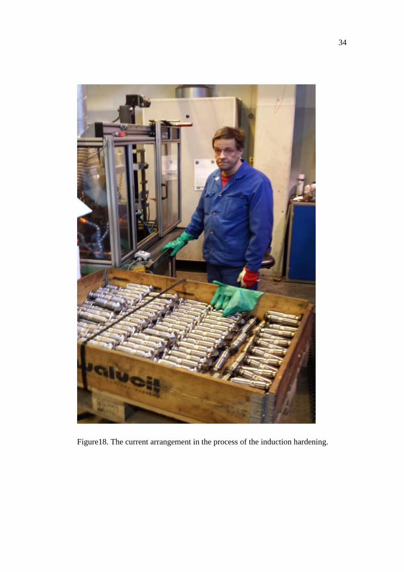
Figure 18 shows how the induction hardening is currently done. The operator is
standing in front of the induction machine whilst the work pieces are placed in a
box behind him. He then takes the work piece and places it in the holder for
hardening process and takes it after hardening. He does that till all the work pieces
are hardened.
34
Figure18. The current arrangement in the process of the induction hardening.

35
6 COST ANALYSIS
6.1 Number of work pieces
The number of work pieces for the cost analyses of the study is based on three
suggested work pieces (ABC) with handling time and hardening time of each of
these pieces. We have estimated the number of work pieces that can be carried out
by the robot and have compared the number to that of human. The average
number of hours of the induction machine is estimated to be thousand five
hundred (1500) per year. In all the three work pieces we estimated the sales of the
services to be €105 per every hour. The variable cost of production both robot and
human is estimated to be twenty percent (20%) of one our sales.
The robot will be working for eight hours a day if there are available work pieces
to be worked on. The operation by human operator is also eight hours in a day and
out of the eight hours one and half hours is for lunch and coffee breaks. Therefore
the actual hours will be six and a half. Tables 1, 2 and 3 show all the information
of the work pieces (ABC) should the robot is compared to a human operator to
cover the average working hours per year.
Table 1 Work piece A
Features Robot Human
Total time 45 seconds 45seconds
Number of hours per year 500 hours 500hours
Number of work pieces 40,000 pieces 32,500 pieces

36
Table 2 Work pieces B
Features Robot Human
Total time 60 seconds 60seconds
Number of hours per year 500 hours 500 hours
Number of work pieces 30,000 pieces 24,375 pieces
Table 3 Work piece C
Features Robot Human
Total time per piece 90 seconds 90seconds
Number of hours 500hours 500 hours
Number of work pieces 20,000 pieces 16,250 pieces
6.1.2 A breakdown of the total cost of the robot
The installation price of the robot is €15,000. Robot tools or grippers are € 4,000:
different gripper will be used for each work piece therefore the more there are
different work pieces the cost increases. The table and crates that the work pieces
will be arranged before the treating is estimated to be € 5,000. Before the robot

37
will start the process, there will be human labor of two hours within a working
day to arrange the work pieces in the crates and even test the hardness of the
component. This labor cost is estimated to be € 9000 should the machine run for
1500 hours. The cost of installation of programmed is estimated to € 2000 for
different work pieces. The maintenance cost is estimated to be € 1000; in reality
the maintenance cost is not that much because the only maintenance to be done is
to lubricate the robot once a year. Table 4 shows the list of features and their cost
for installing the robot.
The total cost of the robot will be € 36,000 and the cost of labor when the machine
is run for 1500 hours is € 4700.
Table 4 The total cost of installing the robot
Feature Cost
Price of robot € 15000
Grippers or tools € 4000
Table and crates € 5000
Programmed installation € 2000
Maintenance cost € 1000
Cost of labour € 9000
Total cost € 36000

38
Table 5 Total work pieces with different heating and handling time
Features Robot Human
Total number of hours 1500 hours 1500 hours
Total number of pieces 90,000 73,125 pieces
variable cost =20% of sales € 0.35 € 0.35
Fixed cost € 36,000 € 47000
Total sales € 1.75 per piece € 1.75 per pie
The total variable cost is assumed to be 20% of the sales of 1500 hours, the robot
and human have the same variable cost within working hours. Table 5 shows the
total number of work pieces that can be done by both the robot and human within
the average hours per year (1500) and the cost involved.
6. 1.3 The cost analysis for using robot
Table 6 shows the cost analysis of the hardening process should the machine be
run by the robot was based on the assumed total work pieces with different
heating and handling time as shown in Table 5. It entails the number of work
pieces, sales, veritable cost, fixed cost, total cost and the income

39
Table 6 Cost analysis for using robot
Work piecs Sales Veriable cost Fixedcost Totalcost Income
0 € 0 € 0 € 36 000 € 36 000 -€ 36 000
15000,00 € 26 250 € 5 250 € 36 000 € 41 250 -€ 15 000
30000,00 € 52 500 € 10 500 € 36 000 € 46 500 € 6 000
45000,00 € 78 750 € 15 750 € 36 000 € 51 750 € 27 000
60000,00 € 105 000 € 21 000 € 36 000 € 57 000 € 48 000
75000,00 € 131 250 € 26 250 € 36 000 € 62 250 € 69 000
90000,00 € 157 500 € 31 500 € 36 000 € 67 500 € 90 000
105000,00 € 183 750 € 36 750 € 36 000 € 72 750 € 111 000
120000,00 € 210 000 € 42 000 € 36 000 € 78 000 € 132 000
Figure19. Breakeven analysis graph for using the robot for induction hardening.
As illustrated in Figure 19 the number of work pieces the robot need to breakeven
is 25714 with a cost of € 41,250. The breakeven point is where the sales line and
the total cost lines meet.
6.1.4 The cost analysis for running the induction machine by human
Table 7 cost analysis of the hardening process should the machine be run by a
human operator, this was based on the assumed total work pieces with different
€ 0
€ 50 000
€ 100 000
€ 150 000
€ 200 000
€ 250 000
0 20000 40000 60000 80000 100000 120000 140000Workpieces
Breakeven analysis for robot
Sales Fixed cost Total cost

40
heating and handling time as shown in Table 5. It entails the number of work
pieces, sales, veritable cost, fixed cost, total cost and the income.
Table 7 Cost analysis by using human
Work pieces Sales Viriable cost Fixed cost Total cost Income
0 € 0 € 0 € 47 000 € 47 000 -€ 47 000
15000,00 € 26 250 € 5 250 € 47 000 € 52 250 -€ 26 000
30000,00 € 52 500 € 10 500 € 47 000 € 57 500 -€ 5 000
45000,00 € 78 750 € 15 750 € 47 000 € 62 750 € 16 000
60000,00 € 105 000 € 21 000 € 47 000 € 68 000 € 37 000
75000,00 € 131 250 € 26 250 € 47 000 € 73 250 € 58 000
90000,00 € 157 500 € 31 500 € 47 000 € 78 500 € 79 000
105000,00 € 183 750 € 36 750 € 47 000 € 83 750 € 100 000
120000,00 € 210 000 € 42 000 € 47 000 € 89 000 € 121 000
Figure 20. The breakeven analysis graph of using the induction machine by a
human operator.
Figure 20 shows that 39167 work pieces and a cost € 57,500 are needed to
breakeven when the induction machine is fully operated by a human operator.
€ 0
€ 50 000
€ 100 000
€ 150 000
€ 200 000
€ 250 000
0 20000 40000 60000 80000 100000 120000 140000
Workpieces
Breakeven analysis for human
Sales Fixed cost Total cost

41
7 CONCLUSIONS
This study was motivated by the need of analyzing the cost of implementing an
industrial robot at Bodycote Vaasa heat treatment plant. The robot is intended to
be used for induction hardening which is currently operated manually.
During the research we found out that implement automated machines or
specifically robots do increase their profit of business organization and also makes
work easier.
It was gathered from the research results that the robot will work on 90000 work
pieces within the average working hours of the induction machine which is 1500
hours and with an income of € 90,000. However, the same number hours (1500)
when used by a human operator will work on 73125 work pieces with an income
of €56,550. Therefore, based on the analysis of this research we come to a
conclusion that it will be worthwhile for Bodycote acquire the robot.
During this research, we found out the robot will work one and half hours more
than a human operator every working day. This is to the fact that the robot will
work constantly during the working day (eight hours) without lunch or coffee
breaks. Therefore work output of the robot is consistent and more predictable as to
determine the production delivery time.
During this research the plant manager of Bodycote Vaasa, Mr. Veli-Pekka
Nurminen was interviewed and he assured to make the working environment of
the robot conducive by providing the necessary educational training for his
employees should the robot is implemented.
7.1 Limitations
The time allocated for conducting this thesis was very limited therefore there
could have been more theoretical information, even though this gives a Clear view
of the thesis. However, this research gives an overview of comparing robot and

42
human operator for induction hardening. There could have been more accurate
and precise results if the actual production data of the induction machine per year
was given.
7.1.1 Recommendation
Although the need of implementing robot for induction hardening is worth, we
recommend it should be implemented if there are enough work pieces to work on,
that is, if the number of work pieces to work on during the year is. That is the
critical number of work pieces to make the acquisition profitable.
In this case we recommend if there is not enough work for the robot then the
induction hardening should be continued to be run by a human operator. If there is
not work for a human operator at induction he can work at the main production
line or do some other work for the company.
43
REFERENCES
/1/ ABB.
HTTP://WWW04.ABB.COM/GLOBAL/SEITP/SEITP202.NSF/C71C66C1F02E
6575C125711F004660E6/89654DE35F1B9214C12575D300435264/$FILE/10+G
OOD_REASONS_JUNE_+09.PDF. Accessed 06.04.2013
/2/ All On Robot. http://www.allonrobots.com/spherical-robots.html.
Accessed 18.04.2013
/3/ Alzheimer Europe. http://www.alzheimer-
europe.org/Research/Understanding-dementia-research/Types-of-research/The-
four-main-approaches. Accessed 27.04.2013
/4/ Bodycote. http://www.bodycote.com/en.aspx. Accessed 29.03.2013
/5/ Bodycote. http://www.bodycote.com/en/services/heat-treatment/case-
hardening-without-subsequent-hardening-operation/nitrocarburising.aspx.
Accessed. 08.05.2013
/6/ Bodycote. http://www.bodycote.com/en/services/heat-treatment/harden-
and-temper/induction-hardening.aspx?keyword=induction+heating. Accessed
08.05.2013
/7/ Bone Frontier Induction. http://www.bonefrontier.com/overview.htm.
Accessed 20.03.2013
/8/ Bright Hub Engineering.
http://www.brighthubengineering.com/manufacturing-technology/30476-what-is-
heat-treatment. Accessed 19.03.2013
/9/ Dawei Induction Heating Machine. http://www.induction-
heating.com.cn/Induction-Heating-Coil-Design-34.html. Accessed 10.04.2013
/10/ Deck India Engineering. http://www.deckindia.com/services.html.
Accessed 08.05.2013
/11/ Direct Industry. http://www.directindustry.com/prod/parker-
electromechanical-automation/gantry-robots-26133-342246.html. Accessed
17.04.2013
44
/12/ Direct Industry. http://www.directindustry.com/prod/staubli-robotics/4-
axis-scara-robots-17645-232952.html. Accessed 17.04.2013
/13/ EFD Induction. http://www.efd-
induction.com/~/media/PDF/Applications/Applications.ashx. Accessed
09.04.2013
/14/ Efunda.
http://www.efunda.com/processes/heat_treat/introduction/heat_treatments.cfm.
Accessed 17.03.2013
/15/ Fluxtrol. http://fluxtrol.com/chap-iii-coil-styles/. Accessed 09.04.2013
/16/ Funding Universe. http://www.fundinguniverse.com/company-
histories/bodycote-international-plc-history/. Accessed 29. 04.2013
/17/ GH Induction Atmospheres. http://www.gh-ia.com/induction-
heating/terms.html#joule. Accessed 01.04.2013
/18/ GH Induction Atmospheres. http://www.gh-
ia.com/induction_heating.html. Accessed 30.03.2013
/19/ Heat Treatment of Metals.
http://web.iitd.ac.in/~suniljha/MEL120/L4_Heat_Treatment_of_Metals.pdf.
Accessed 20.03.2013
/20/ Look At Vietnam. http: //www.lookatvietnam.com/2009/11/local-robots-
make-good-at-tokyo-expo.html. Accessed 17.04.2013
/21/ Metals. http://metals.about.com/od/metallurgy/g/Tempering.htm.
Accessed 20.03.2013
/22/ Rayan. http://www.technologystudent.com/pdf2/case1.pdf. Accessed
08.05.2013
/23/ Research Methodology.
http://www.newagepublishers.com/samplechapter/000896.pdf. Accessed
27.04.2013
/24/ Robotics. http://www.galileo.org/robotics/intro.html. Accessed 01.04.2013
/25/ Robotics. http://smerobot-
tools.prospektiv.de/robotic/eng/robot_types.html. Accessed 04.04.2013
45
/26/ Robotics Youngester. http://robotics.youngester.com/2008/11/kukas-
palletizing-robot-technology.html. Accessed 17.04.2013
/27/ Robot Matrix. http://www.robotmatrix.org/SCARARobotic.htm. Accessed
17.03.2013
/28/ Roboto Biko. http://www.robotobibok.com/comprehensive-guide-
defining-basic.html. Accessed 01.04.2013
/29/ RobotWorx http://www.robots.com/faq/show/what-are-the-main-parts-of-
an-industrial-robot. Accessed 04.04.2013
/30/ RobotWorx. http://www.robots.com/faq/show/what-are-the-main-types-of-
robots. Accessed 17.04.2013
/31/ RobotWorx. http://www.used-robots.com/articles.php?tag=1557.
Accessed 20.04.2013
/32/ Saarstahl.
http://www.saarstahl.com/arten_der_waermebehandlung.html?L=1. Accessed
20.03.2013
/33/ Science Daily.
http://www.sciencedaily.com/articles/i/industrial_robot.htm. Accessed 01.04.2013
/34/ Siasun. http://www.siasun.com/english/products-view-view.aspx?id=345#.
Accessed 21.05.2013
/2/ Somp. http://www.somp.com.lb/heattreatment.php. Accessed 19.03.2013
/36/ Thomasnet. http://www.thomasnet.com/articles/automation-
electronics/industrial-robot-basics. Accessed 04.04.2013
/37/ Turbo Squid. http://www.turbosquid.com/3d-models/polar-robot-
max/407866. Accessed 17.04.2013
/38/ Wikipedia. http://en.wikipedia.org/wiki/Carburizing#cite_note-. Accessed
07.05.2013
/39/ YouTube. http://www.youtube.com/watch?v=K3vwlQi2_rM. Accessed
23.03.2013

46
APPENDIX I
Interview
Respondent: Mr. Veli-Pekka Nurminen, the Plant manager of Bodycote
Låmpökåsittely Oy Vaasa. The interview was heard at the company premises in
Vaasa, Finland in April 2013.
Contact information: Bodycote Låmpökåsittely Oy. Vasaratie 2 65350 Vaasa,
Finland. Tel: +358207466360.

47
APPENDIX II
Questionnaire guide for the interview
1. A brief background about Bodycote?
2. What is your current percentage in delivery efficiency?
3. How satisfied are your customers with current delivery time?
4. How many work pieces do you receive per week
5. How long does it take to work on them?
6. Why do you wont to implement industrial robot?
7. Will the robot affect other sections apart from induction section?
8. How likely are your employees ready to accept the introduction of a robot?
9. What measures have you designed to ensure that employees adapt to the
introduction and use of a robot without resistance?