emittance adapter for a diffraction limited synchrotron - SLAC
5
SLAC-PUB-14808 EMITTANCE ADAPTER FOR A DIFFRACTION LIMITED SYNCHROTRON RADIATION SOURCE Alexander Wu Chao * and Pantaleo Raimondi # Abstract We investigate the possibility of reaching very small horizontal and vertical emittances inside an undulator in a storage ring, by means of a local exchange of the apparent horizontal and vertical emittances, performed with a combination of skew quadrupoles and one solenoid in a dedicated insertion line in the storage ring. The insertion leaves the ring parameters and its optical properties unaffected. This scheme could greatly relax the emittance requirements for a diffraction limited synchrotron light source. The lattice derivation and design is described. INTRODUCTION The idea of flat-to-round and round-to-flat adapters has been first introduced by Derbenev [1] and extended by him and many others [2-10]. He first envisioned applying it to a storage ring collider to form round beams at the collision point to minimize the effect of beam-beam resonances. This idea has also been considered for electron cooling [2,7]. The production of a very flat beam from a round photocathode immersed in a solenoid, followed by a round-to-flat adapter lattice, has been experimentally demonstrated [9,10]. In the electron cooler application, the beam inside the solenoid has very small angular divergences σ x’ and σ y’ . This beam could be used for electron beam cooling because of its extremely cold temperature. We can use the same technique in a back-to-back configuration in a storage ring, for the purpose of generating a diffraction- limited X-ray synchrotron light source [5]. In order to have coherent or quasi-coherent radiation, the beam emittances ε x and ε y have both to be less than λ/4π, where λ is the X-ray wavelength. This is very difficult to achieve for ε x , requiring complicated and demanding storage ring lattice designs, powerful damping wigglers, tight tolerances and orbit controls. The small dispersion function and the corresponding strong sextupoles also lead to small dynamic apertures. With the proposed scheme [5], the storage ring lattice can have relaxed requirements on ε x , as long as ε y can be made very small, as routinely obtained in electron storage rings. In the straight section reserved for any insertion device, a flat-to-round adapter is first inserted; after which, the beam enters a solenoid that has an aperture sufficiently large to accommodate a radiator (e.g. an undulator) inside. After the solenoid, a round-to-flat adapter (mirror image of the flat-to-round adapter) restores the original coupling. The arc ring lattice should provide a beam as flat as possible (ε y <<ε x ), so that π λ ε ε 4 / x < y for the radiation wavelength of interest. Quantities ε x and ε y are the eigen-emittances of the storage ring in the canonical phase space (x, p x , y, p y ). The adapters and the solenoid are magnets whose symplectic transport maps will not affect them [12]. It is therefore not possible to make the canonical momenta p x and p y very small simultaneously inside the solenoid. However, in the solenoid, the mechanical momenta x’ and y’ can be made small simultaneously without violating symplecticity because they are not the canonical coordinates. The adapter makes them determined solely by the small initial ε y . Fortunately, radiation cares about the apparent emittances in the (x, x’, y, y’) space rather than the true emittances in the (x, p x , y, p y ) space. In the solenoid, they are related as: x’=p x - k s y/2; y’=p y + k s x/2; k s =B s /(Bρ) 0 with B s the solenoid magnetic field and (Bρ) 0 the magnetic rigidity of the electron beam. The adapter and solenoid optics make p x cancel with k s y/2 (and p y with k s x/2), so x’ (and y’) will be small even when p x (and p y ) are not. OPTICS DESIGN We consider a regular ring lattice that, at its junction to the flat-to-round section, has β x = β y , and α x = α y = 0. We also assume that the lattice has dispersion suppressors at its ends so that the dispersion vanishes in the insertion. We describe the particle motion using the canonical coordinates X can = (x, p x , y, p y ) and later transform the description to X = (x, x’, y, y’). The particle motion is described by [6, 12] X can = Va: − − = y y y y y y y y x x x x x x x x V ϕ β ϕ β ϕ β ϕ β ϕ β ϕ β ϕ β ϕ β cos 1 sin 1 0 0 sin cos 0 0 0 0 cos 1 sin 1 0 0 sin cos * SLAC National Accelerator Lab., 2575 Sand Hill Road, Menlo Park, CA 94025, USA; Work supported by DoE contract D-AC02- 76SF00515. # LNF-INFN, Via E. Fermi 40, 00044 Frascati (Rome), Italy.
Transcript of emittance adapter for a diffraction limited synchrotron - SLAC

SLAC-PUB-14808
EMITTANCE ADAPTER FOR A DIFFRACTION LIMITED SYNCHROTRON RADIATION SOURCE
Alexander Wu Chao* and Pantaleo Raimondi#
Abstract
We investigate the possibility of reaching very small horizontal and vertical emittances inside an undulator in a storage ring, by means of a local exchange of the apparent horizontal and vertical emittances, performed with a combination of skew quadrupoles and one solenoid in a dedicated insertion line in the storage ring. The insertion leaves the ring parameters and its optical properties unaffected. This scheme could greatly relax the emittance requirements for a diffraction limited synchrotron light source. The lattice derivation and design is described.
INTRODUCTION The idea of flat-to-round and round-to-flat adapters
has been first introduced by Derbenev [1] and extended by him and many others [2-10]. He first envisioned applying it to a storage ring collider to form round beams at the collision point to minimize the effect of beam-beam resonances. This idea has also been considered for electron cooling [2,7]. The production of a very flat beam from a round photocathode immersed in a solenoid, followed by a round-to-flat adapter lattice, has been experimentally demonstrated [9,10].
In the electron cooler application, the beam inside the solenoid has very small angular divergences σx’ and σy’. This beam could be used for electron beam cooling because of its extremely cold temperature. We can use the same technique in a back-to-back configuration in a storage ring, for the purpose of generating a diffraction-limited X-ray synchrotron light source [5].
In order to have coherent or quasi-coherent radiation, the beam emittances εx and εy have both to be less than λ/4π, where λ is the X-ray wavelength. This is very difficult to achieve for εx, requiring complicated and demanding storage ring lattice designs, powerful damping wigglers, tight tolerances and orbit controls. The small dispersion function and the corresponding strong sextupoles also lead to small dynamic apertures.
With the proposed scheme [5], the storage ring lattice can have relaxed requirements on εx, as long as εy can be made very small, as routinely obtained in electron storage rings. In the straight section reserved for any insertion device, a flat-to-round adapter is first inserted; after which, the beam enters a solenoid that has an aperture
sufficiently large to accommodate a radiator (e.g. an undulator) inside. After the solenoid, a round-to-flat adapter (mirror image of the flat-to-round adapter) restores the original coupling.
The arc ring lattice should provide a beam as flat as possible (εy<<εx), so that πλεε 4/x <y for the
radiation wavelength of interest. Quantities εx and εy are the eigen-emittances of the
storage ring in the canonical phase space (x, px, y, py). The adapters and the solenoid are magnets whose symplectic transport maps will not affect them [12]. It is therefore not possible to make the canonical momenta px and py very small simultaneously inside the solenoid. However, in the solenoid, the mechanical momenta x’ and y’ can be made small simultaneously without violating symplecticity because they are not the canonical coordinates. The adapter makes them determined solely by the small initial εy. Fortunately, radiation cares about the apparent emittances in the (x, x’, y, y’) space rather than the true emittances in the (x, px, y, py) space. In the solenoid, they are related as:
x’=px - ksy/2; y’=py + ksx/2; ks=Bs/(Bρ)0 (1)
with Bs the solenoid magnetic field and (Bρ)0 the magnetic rigidity of the electron beam. The adapter and solenoid optics make px cancel with ksy/2 (and py with ksx/2), so x’ (and y’) will be small even when px (and py) are not.
OPTICS DESIGN We consider a regular ring lattice that, at its junction
to the flat-to-round section, has βx = βy, and αx = αy = 0. We also assume that the lattice has dispersion suppressors at its ends so that the dispersion vanishes in the insertion.
We describe the particle motion using the canonical coordinates Xcan = (x, px, y, py) and later transform the description to X = (x, x’, y, y’).
The particle motion is described by [6, 12] Xcan = Va:
⎥⎥⎥⎥⎥⎥⎥⎥
⎦
⎤
⎢⎢⎢⎢⎢⎢⎢⎢
⎣
⎡
−
−
=
yy
yy
yyyy
xx
xx
xxxx
V
ϕβ
ϕβ
ϕβϕβ
ϕβ
ϕβ
ϕβϕβ
cos1sin100
sincos00
00cos1sin100sincos
* SLAC National Accelerator Lab., 2575 Sand Hill Road, Menlo Park, CA 94025, USA; Work supported by DoE contract D-AC02-76SF00515. # LNF-INFN, Via E. Fermi 40, 00044 Frascati (Rome), Italy.

a =
2!x sin"x2!x cos"x2!y sin"y
2!y cos"y
!
"
#######
$
%
&&&&&&&
;
Xcan =Va =
2!x"x sin(# x +$x )
2"x !x cos(# x +$x )
2!y"y sin(# y +$y )
2"y !y cos(# y +$y )
!
"
#######
$
%
&&&&&&&
At the entrance to the solenoid, the particle motion is described by Xcan = Ub, where U is the symplectic matrix consisting of the circular mode basis vectors [6]:
U =
1kssin!+ !
1kscos!+
1kssin!! !
1kscos!!
ks2cos!+
ks2sin!+
ks2cos!!
ks2sin!!
1kscos!+
1kssin!+ !
1kscos!! !
1kssin!!
!ks2sin!+
ks2cos!+
ks2sin!! !
ks2cos!!
"
#
$$$$$$$$$$$$
%
&
''''''''''''
;
cos2sin2cos2sin2
⎥⎥⎥⎥⎥
⎦
⎤
⎢⎢⎢⎢⎢
⎣
⎡
=
−−
−−
++
++
θε
θε
θε
θε
b
( )
( )( )
( ) ⎥⎥⎥⎥⎥⎥⎥⎥⎥⎥
⎦
⎤
⎢⎢⎢⎢⎢⎢⎢⎢⎢⎢
⎣
⎡
Δ−Δ
Δ−Δ
Δ+Δ
Δ+Δ−
==
−−++
−−++
−−++
−−++
coscos2
sinsin2
sinsin2
coscos2
εε
εε
εε
εε
s
s
s
s
can
kk
kk
UbX
where Δ+=ϕ++θ+ and Δ-=ϕ-+θ-. In the language of circular modes, this is equivalent to choose envelope function β = 2/ks and α = 0 (ks > 0).
At a distance z into the solenoid, the motion is described by Xcan = MsolUb:
zk
kkkk
kkkk
M
ss
ss
ss
ss
ss
ss
ss
ssss
ss
s
sss
s
s
sol
=
⎥⎥⎥⎥⎥⎥⎥⎥⎥
⎦
⎤
⎢⎢⎢⎢⎢⎢⎢⎢⎢
⎣
⎡
−−
−−
−−=
ϕ
ϕϕϕ
ϕ
ϕϕϕ
ϕ
ϕϕϕ
ϕ
ϕϕϕ
ϕ
2cossin
4sin21
2sin
2
sin12
cos2
sin2sin21
sin21
2sin
22cossin
4
2sin2sin
21sin1
2cos
22
22
22
22
Xcan =
!2ks
!+ cos("+ +#+ + ksz)+ !! cos("! +#! )( )ks2
!+ sin("+ +#+ + ksz)+ !! sin("! +#! )( )2ks
!+ sin("+ +#+ + ksz)! !! sin("! +#! )( )ks2
!+ cos("+ +#+ + ksz)! !! cos("! +#! )( )
"
#
$$$$$$$$$$$$
%
&
''''''''''''
The “+” mode (“Lamor” mode) advances with the solenoid phase ksz, but the “-” mode’s phase stays still.
The adapter matches the flat optics of the ring arcs to the round optics of the solenoid. It is designed to provide a transport map Madp=UV-1, which is:
⎥⎥⎥⎥⎥⎥⎥⎥⎥⎥⎥⎥⎥⎥⎥
⎦
⎤
⎢⎢⎢⎢⎢⎢⎢⎢⎢⎢⎢⎢⎢⎢⎢
⎣
⎡
Δ−ΔΔΔ−
Δ−Δ−ΔΔ
ΔΔΔΔ
Δ−ΔΔ−Δ
=
yyxx
yyxx
yyxx
yyxx
sky
y
skskx
x
sk
sky
skyskx
skx
sky
y
skskx
x
sk
sky
skyskx
skx
adpM
cos2
sin21cos
2sin
21
sincos1sincos1
sin2
cos21sin
2cos
21
cossin1cossin1
β
β
β
β
β
β
β
β
β
β
β
β
β
β
β
β
with Δx=ϕ+-ϕx and Δy=ϕ--ϕy. After inserting this section, a particle with initial
condition Xcan = Va at the end of the regular cell will be transported to an arbitrary distance z inside the solenoid:
Xcan =MsolMadpVa =Msol (UV!1)Va =MsolUa
Xcan =
!2ks
!x cos(!+ +"x + ksz)+ !y cos(!! +"y )( )ks2
!x sin(!+ +"x + ksz)+ !y sin(!! +"y )( )2ks
!x sin(!+ +"x + ksz)! !y sin(!! +"y )( )ks2
!x cos(!+ +"x + ksz)! !y cos(!! +"y )( )
"
#
$$$$$$$$$$
%
&
''''''''''
We have simply made the emittance exchanges εx à ε+ and εy à ε- by the flat-to-round insertion.
The map Madp is chosen to satisfy the conditions: βx= βy, ! + =! x-π/4, ! - =! y+π/4. It can be written as: 120 !
12
0
0 12
0 !12
120 1
20
0 12
0 12
"
#
$$$$$$$$
%
&
''''''''
0 !2!x
ks0 0
ks2!x
0 0 0
0 0 !2ks!x
0
0 0 0 !ks!x
2
"
#
$$$$$$$$
%
&
''''''''
12
0 120
0 12
0 12
!12
0 120
0 !120 1
2
"
#
$$$$$$$$
%
&
''''''''
The middle map is that of a quadrupole channel (three quadrupoles) with x phase advance of 3π/2 and y phase advance of π. The two adjacent matrices mean that the triplet channel is rotated by 45o so that the quadrupoles become skew. With this insertion, a particle at the entrance of the insertion is transported inside the solenoid with Xcan(z) = MsolUa. The result is:
Xcan (z) =
!2ks
!x cos(" x +#4+$x + ksz)+ !y cos(" y +
#4+$y )
"
#$
%
&'
ks2
!x sin(" x !#4+$x + ksz)+ !y sin(" y +
#4+$y )
"
#$
%
&'
2ks
!x sin(" x !#4+$x + ksz)! !y sin(" y +
#4+$y )
"
#$
%
&'
ks2
!x cos(" x +#4+$x + ksz)! !y cos(" y +
#4+$y )
"
#$
%
&'
(
)
************
+
,
------------
BEAM CHARACTERISTICS IN THE SOLENOID
The radiation at the radiator cares about X and not Xcan, and X inside the solenoid is X(z)= Mexit Xcan(z) with:
⎥⎥⎥
⎦
⎤
⎢⎢⎢
⎣
⎡−
=
1002010002100001
s
sexit
k
kM
⎥⎥⎥⎥⎥⎥⎥⎥⎥⎥
⎦
⎤
⎢⎢⎢⎢⎢⎢⎢⎢⎢⎢
⎣
⎡
++−
⎟⎠
⎞⎜⎝
⎛++−++−
++
⎟⎠
⎞⎜⎝
⎛++++++−
=
)4
cos(2
)4
sin()4
sin(2
)4
sin(2
)4
cos()4
cos(2
)(
yyys
yyysxxxs
yyys
yyysxxxs
k
zkk
k
zkk
zX
θπ
ϕε
θπ
ϕεθπ
ϕε
θπ
ϕε
θπ
ϕεθπ
ϕε
Only the vertical emittance εy enters x’ and y’, as
desired, while x and y are large, mainly determined by εx. The beam’s appearance has a large transverse dimension but extremely small divergence. The beam is almost perfectly laminar.
We now calculate the Σ matrix of the second moments of the beam’s transverse distribution. The beam’s Σ0 at the end of the regular cells is:
!0 =
!x"x 0 0 00 "x !x 0 00 0 !x"y 0
0 0 0 "y !x
"
#
$$$$$
%
&
'''''
The total transport map from the end of regular cells to inside of solenoid is MsolMadp. With this map, the Σ0 matrix is transformed to (in the Xcan coordinate):
!1 =
!x +!yks
0 0 "12(!x "!y )
0 ks4(!x +!y )
12(!x "!y ) 0
0 12(!x "!y )
!x +!yks
0
"12(!x "!y ) 0 0 ks
4(!x +!y )
#
$
%%%%%%%%%%%
&
'
(((((((((((
Note that Msol depends on z but the beam distribution inside the solenoid is independent of z. This results from the optics matching by the adapter. The beam is optically “matched” into the solenoid.
Eigen-emittances can be calculated from the Σ matrices; they are just the eigen-values of the matrix iJΣ, where J is the symplectic form. Both Σ0 and Σ1 have eigen-emittances equal to εx and εy.
In the X coordinates, we then transport Σ1 by Mexit:
!2 =Mexit!1MexitT =
(!x +!y ) ks 0 0 !y0 !yks "!y 0
0 "!y (!x +!y ) ks 0
!y 0 0 !yks
#
$
%%%%%%
&
'
((((((
From Σ2 we obtain the beam distribution moments:
! x =! y = ("x +"y ) / ks and! x ' =! y ' = "yks inside the solenoid, all independent of z.
After the solenoid, the matched round beam is brought back to its flat configuration with a reversed round-to-flat adapter, so the insertion is transparent to the ring.
The two “projected-emittances” using Σ2 are equal and found to be !x!y +!y
2 which is approximately equal to
!x!y . The Diffraction limit requirement will be:
!x!y < " / 4# This is easier to achieve than!x < " / 4# since today most storage rings light sources routinely reach εy < 10-3εx. It should be pointed out that, since the beam is very laminar, the X-ray optics to match it will have a long Rayleigh length [13]: syxxxR kL εεσσ ≈≈ ' . The
transverse coherence properties of the light generated by such beam have to be further studied.
The electron motion and the light properties in the presence of the combined solenoid and undulator will require more detailed analysis. At the lowest order, the orbit distortion caused by the radiator should vanish outside of the solenoid. The first order optics remains the same as without the radiator.
A DESIGN EXAMPLE All lattice designs, including regular cells and adapters
are straightforward and should not impose technical challenges. The main design issue is the undulator inside the solenoid. Key parameters are the solenoid strength ks, its length L and physical aperture R. L and R are only constrained by the needs of the radiator and not from optics matching.
Choice of ks is related to the beam characteristics at the radiator. In addition one should note that the skew quadrupole strengths depend on ks. In general, extreme values of ks should be avoided. Typically, ks should be in the range [0.1 m, 1.0 m].
Figure 1 shows an example of the adapter design for the SuperB case. On both ends, a dispersion suppressor cancels the arc dispersion and a triplet matches the envelope functions for the adapter. In this example we choose βx = βy = 6.0 m, αx = αy = 0. Subsequently there are two adapter triplets, each one generating the following transfer matrix:
⎥⎥⎥⎥⎥⎥⎥⎥⎥
⎦
⎤
⎢⎢⎢⎢⎢⎢⎢⎢⎢
⎣
⎡
−−−
−−
++−
++
=
)4
cos()4
sin(100
)4
sin()4
cos(00
00)4
cos()4
sin(1
00)4
sin()4
cos(
πϕ
πϕ
β
πϕβ
πϕ
πϕ
πϕ
β
πϕβ
πϕ
x
x
x
x
V
We have set ϕ =π/2 as an example, but its value is
arbitrary. In general the incoming parameters β and α in the adapter section are arbitrary as well, provided that they are equal in the two planes.
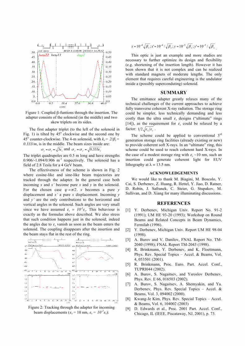
Figure 1: Coupled β-funtions through the insertion. The adapter consists of the solenoid (in the middle) and two
skew triplets on its sides.
The first adapter triplet (to the left of the solenoid in Fig. 1) is tilted by 45o clockwise and the second one by 45o counter-clockwise. The 4-m solenoid, with ks = 2/βx = 0.333/m, is in the middle. The beam sizes inside are:
! x =! y ! 3"x and ! x ' =! y ' = 0.333"y The triplet quadrupoles are 0.5 m long and have strengths 0.906/-1.094/0.906 m-1 respectively. The solenoid has a field of 2.8 Tesla for a 4 GeV beam.
The effectiveness of the scheme is shown in Fig. 2 where cosine-like and sine-like beam trajectories are tracked through the adapter. In the general case both incoming x and x’ become pure x and y in the solenoid. For the chosen case ϕ =π/2, x becomes a pure y displacement and x’ a pure x displacement. Incoming y and y’ are the only contributions to the horizontal and vertical angles in the solenoid. Such angles are very small since we have assumed εy = 10-2εx. This behaviour is exactly as the formulas above described. We also stress that such condition happens just in the solenoid; indeed the angles due to εx vanish as soon as the beam enters the solenoid. The coupling disappears after the insertion and the beam stays flat in the rest of the ring.
Figure 2: Tracking through the adapter for incoming
beam displacements (εx = 10 nm, εy = 10-2εx):
xxxx yyxx ββββ /10';10;/10';10 5544 −−−− ==== .
This optic is just an example and more studies are necessary to further optimize its design and flexibility (e.g. shortening of the insertion length). However it has been shown that it is not complex and can be realized with standard magnets of moderate lengths. The only element that requires careful engineering is the undulator inside a (possibly superconduting) solenoid.
SUMMARY The emittance adapter greatly relaxes many of the
technical challenges of the current approaches to achieve fully transverse coherent X-ray radiation. The storage ring could be simpler, less technically demanding and less costly than the ultra small εx designs (“ultimate” rings [14]), as the requirement for εx could be relaxed by a factor: 1 2 !x !y .
The scheme could be applied to conventional 3rd generation storage ring facilities (already existing or new) to provide coherent soft X-rays. In an “ultimate” ring, this scheme could be used to reach coherent hard X-rays. In the case of a modest storage ring with εx ~10 nm, such an insertion could generate coherent light for EUV lithography at λ = 13.5 nm.
ACKNOWLEDGEMENTS We would like to thank M. Biagini, M. Boscolo, Y.
Cai, S. Derbenev, Z. Huang, R. Hettel, Y. Jiao, D. Ratner, D. Robin, J. Safranek, C. Steier, G. Stupakov, M. Sullivan, and D. Xiang for many illuminating discussions.
REFERENCES [1] Y. Derbenev, Michigan Univ. Report No. 91-2
(1991); UM HE 93-20 (1993); Workshop on Round Beams and Related Concepts in Beam Dynamics, Fermilab (1996).
[2] Y. Derbenev, Michigan Univ. Report UM HE 98-04 (1998).
[3] A. Burov and V. Danilov, FNAL Report No. TM-2040 (1998); FNAL Report TM-2043 (1998).
[4] R. Brinkmann, Y. Derbenev, and K. Floettmann, Phys. Rev. Special Topics – Accel. & Beams, Vol. 4, 053501 (2001).
[5] R. Brinkmann, Proc. Euro. Part. Accel. Conf., TUPRI044 (2002).
[6] A. Burov, S. Nagaitsev, and Ysroslov Derbenev, Phys. Rev. E 66, 016503 (2002).
[7] A. Burov, S. Nagaitsev, A. Shemyakin, and Ya. Derbenev, Phys. Rev. Special Topics – Accel. & Beams, Vol. 3, 094002 (2000).
[8] Kwang-Je Kim, Phys. Rev. Special Topics – Accel. & Beams, Vol. 6, 104002 (2003)
[9] D. Edwards et al., Proc. 2001 Part. Accel. Conf., Chicago, IL (IEEE, Piscataway, NJ, 2001), p. 73.
[10] P. Piot, Y.-E. Sun, K.-J. Kim, Phys. Rev. Special Topics – Accel. & Beams, Vol. 9, 031001 (2006).
[11] A. Dragt, F. Neri, G. Rangarajan, Phys. Rev. A 45, 2572 (1992).
[12] E.D. Courant, H.S. Snyder, Ann. Phys. 3, 1 (1958). [13] A.M.Kondratenko and E.L.Saldin, Dokl. Akad.
Nauk. SSSR v.249, p.843 (1979); Part. Accel. v.10, p.207 (1980); Zhurnal Tech. Fiz. v.51 p.1633 (1981).
[14] See, for example, M. Bei et al., to be published in Nucl. Inst. Meth. In Phys. Res. A (2011).