Emissions Recall Code: 23U3 REVISION
73
The repair information in this document is intended for use only by skilled technicians who have the proper tools, equipment and training to correctly and safely maintain your vehicle. These procedures are not intended to be attempted by “do-it-yourselfers,” and you should not assume this document applies to your vehicle, or that your vehicle has the condition described. To determine whether this information applies, contact an authorized Volkswagen dealer. 2017 Volkswagen Group of America, Inc. All Rights Reserved. August 2017 23U3 Page 1 of 73 Emissions Recall Code: 23U3 REVISION Subject 2.0L TDI Engine (GEN 1) Emissions Modification – Customer Only (Retail Sold) USA ONLY Release Date August 24, 2017 Revision Summary Updated loaner/rental and label placement instructions. Important Repair Information! CAMPAIGN 24CV MUST BE COMPLETED BEFORE BEGINNING THE 23U3 CAMPAIGN! Over the next few weeks there will be updates made to ODIS and the campaign circular. Do not retain any hard copies of campaign circulars – only refer to the electronic copies posted to Elsa and ServiceNet. Affected Vehicles U.S.A. ONLY: 2009-2014 MY Volkswagen 2.0L TDI (Gen 1), Customer Only (Retail Sold) Country Model Year Vehicle Carline USA 2009‐2014 Jetta USA 2009‐2014 Jetta SportWagen USA 2013‐2014 Beetle USA 2013‐2014 Beetle Convertible USA 2010‐2014 Golf Check Campaigns/Actions screen in Elsa on the day of repair to verify that a VIN qualifies for repair under this action. Elsa is the only valid campaign inquiry & verification source. Campaign status must show “open.” If Elsa shows other open action(s), inform your customer so that the work can also be completed at the same time the vehicle is in the workshop for this campaign. Problem Description The Environmental Protection Agency and California Air Resources Board have determined that Volkswagen vehicles equipped with a 2.0L 4-cylinder TDI engine do not comply with applicable emissions regulations. The emissions control systems on the vehicles will not control emissions under off-cycle conditions as effectively as during the federal test procedure. The extent of the emissions increase under off-cycle conditions depends upon how the vehicles are driven. Corrective Action Install updated emissions control system parts and software, install a TDI Emissions Modification – Proof of Completion Label and install a Supplemental Vehicle Emissions Control Information Label. At this time, affected new and used vehicles in dealer inventory are not included in this emissions modification release. If the vehicle has been modified by the customer prior to receiving the emissions modification in a manner that may yield a non-compliant emissions system (for example, removal of a catalyst, installation of parts that impact emissions or emissions- related parts, or modifications to the ECU or computer software of the vehicle), Volkswagen may not be able to perform the emissions modification until the customer corrects such modification. Parts Information 03L907281B (Glow Plug Control Module): Due to the low replacement rate, part # 03L907281B will not be allocated. If this part is needed to support scheduled vehicle repair, submit your request with VIN to [email protected]. 1K0-298-101-A (Base Kit 1), 1K0-254-402-AX (NOx Catalyst), 1K0-298-101 –X (Base Kit 2): Parts will be allocated prior to owner notification. If allocated parts have been used and your
Transcript of Emissions Recall Code: 23U3 REVISION
The repair information in this document is intended for use only by skilled technicians who have the proper tools, equipment and training to correctly and safely maintain your vehicle. These procedures are not intended to be attempted by “do-it-yourselfers,” and you should not assume this document applies to your vehicle, or that your vehicle has the condition described. To determine whether this information applies, contact an authorized Volkswagen dealer. 2017 Volkswagen Group of America, Inc. All Rights Reserved.
August 2017 23U3 Page 1 of 73
Emissions Recall Code: 23U3 REVISION
Subject 2.0L TDI Engine (GEN 1) Emissions Modification – Customer Only (Retail Sold) USA ONLY
Release Date August 24, 2017
Revision Summary Updated loaner/rental and label placement instructions.
Important Repair Information!
CAMPAIGN 24CV MUST BE COMPLETED BEFORE BEGINNING THE 23U3 CAMPAIGN!
Over the next few weeks there will be updates made to ODIS and the campaign circular. Do not retain any hard copies of campaign circulars – only refer to the electronic copies posted to Elsa and ServiceNet.
Affected Vehicles U.S.A. ONLY: 2009-2014 MY Volkswagen 2.0L TDI (Gen 1), Customer Only (Retail Sold)
Country Model Year Vehicle Carline
USA 2009‐2014 Jetta
USA 2009‐2014 Jetta SportWagen
USA 2013‐2014 Beetle
USA 2013‐2014 Beetle Convertible
USA 2010‐2014 Golf
Check Campaigns/Actions screen in Elsa on the day of repair to verify that a VIN qualifies for repair under this action. Elsa is the only valid campaign inquiry & verification source.
Campaign status must show “open.”
If Elsa shows other open action(s), inform your customer so that the work can also be completed at the same time the vehicle is in the workshop for this campaign.
Problem Description The Environmental Protection Agency and California Air Resources Board have determined that Volkswagen vehicles equipped with a 2.0L 4-cylinder TDI engine do not comply with applicable emissions regulations. The emissions control systems on the vehicles will not control emissions under off-cycle conditions as effectively as during the federal test procedure. The extent of the emissions increase under off-cycle conditions depends upon how the vehicles are driven.
Corrective Action Install updated emissions control system parts and software, install a TDI Emissions Modification – Proof of Completion Label and install a Supplemental Vehicle Emissions Control Information Label.
At this time, affected new and used vehicles in dealer inventory are not included in this emissions modification release.
If the vehicle has been modified by the customer prior to receiving the emissions modification in a manner that may yield a non-compliant emissions system (for example, removal of a catalyst, installation of parts that impact emissions or emissions- related parts, or modifications to the ECU or computer software of the vehicle), Volkswagen may not be able to perform the emissions modification until the customer corrects such modification.
Parts Information 03L907281B (Glow Plug Control Module): Due to the low replacement rate, part # 03L907281B will not be allocated. If this part is needed to support scheduled vehicle repair, submit your request with VIN to [email protected].
1K0-298-101-A (Base Kit 1), 1K0-254-402-AX (NOx Catalyst), 1K0-298-101 –X (Base Kit 2): Parts will be allocated prior to owner notification. If allocated parts have been used and your

The information in this document is intended for use only by skilled technicians who have the proper tools, equipment and training to correctly and safely maintain your vehicle. These procedures are not intended to be attempted by “do-it-yourselfers,” and you should not assume this document applies to your vehicle, or that your vehicle has the condition described. To determine whether this information applies, contact an authorized Volkswagen dealer. 2017 Volkswagen Group of America, Inc. All Rights Reserved.
August 2017 23U3 Page 2 of 73
dealership is at the weekly Upper Order Limit, please submit the backordered sales document number to [email protected] to have additional parts released.
Code Visibility On or about August 11, 2017, this campaign code showed open and available for repair on affected vehicles in Elsa.
On or about August 11, 2017, affected vehicles were identified and open for repair with this campaign code in the VIN Lookup tool at www.vw.com.
Owner Notification Owner notification took place on August 05, 2017.
Loaner/Rental Vehicle Dealers should offer a loaner/rental vehicle to all customers. The loaner/rental can be a non-Volkswagen brand vehicle.
Emissions Campaigns Requirements
(CALIFORNIA ONLY)
The California Air Resources Board and the Department of Motor Vehicles (DMV) require emissions-related campaigns to be completed prior to vehicle registration renewal. When campaign work is done you must provide the owner with a signed “Vehicle Emission Recall – Proof of Correction” certificate (RC EMISCAVWAU). Order certificates online via the Compliance Label Ordering portal at www.vwhub.com.
Additional Information Please alert everyone in your dealership about this action, including Sales, Service, Parts and Accounting personnel. Contact Warranty if you have any questions.
Fill out and affix the appropriate TDI Emissions Modification – Proof of Completion Label and the appropriate Supplemental Vehicle Emissions Control Information Label after work is complete. Additional shipments will be released based on the volume of completed repairs claimed through SAGA. The parts will not be available for order through the website at this time.

The repair information in this document is intended for use only by skilled technicians who have the proper tools, equipment and training to correctly and safely maintain your vehicle. These procedures are not intended to be attempted by “do-it-yourselfers,” and you should not assume this document applies to your vehicle, or that your vehicle has the condition described. To determine whether this information applies, contact an authorized Volkswagen dealer. 2017 Volkswagen Group of America, Inc. All Rights Reserved.
August 2017 23U3 Page 3 of 73
Claim Entry Instructions
After campaign has been completed, enter claim as soon as possible to help prevent work from being duplicated elsewhere. Attach the Elsa screen print showing action open on the day of repair to the repair order.
If customer refused campaign work:
U.S. dealers: Submit request via WISE under the Campaigns/Update/Recall Closure option.
Service Number 23U3
Damage Code 0099
Parts Vendor Code WWO
Claim Type Sold vehicle: 7 10
Causal Indicator Mark Base Kit I as causal part*
Vehicle Wash Do not claim wash under this action.
Loaner/Rental Vehicle Customers are eligible to receive a loaner/rental vehicle.
Criteria I.D. 01
Install Base Kit I and Base Kit II components, install NOx catalyst, install glow plug control module, perform software update, and *install a supplemental Vehicle Emissions Control Information label and TDI Emissions Modification Label.
Labor operation: 2360 22 99 570 T.U.
Labels are sent free of charge. They cannot be charged to this campaign. LOANER/RENTAL claiming on next page
Quantity Part number Description 1.00 1K0298101A Base Kit I* 1.00 1K0254402AX NOx Catalyst 1.00 1K0298101X Base Kit II 1.00 (if required) 03L907281B Glow Plug Control Module
Criteria I.D. 02
Install Base Kit I components, install NOx catalyst, perform software update, and *install a supplemental Vehicle Emissions Control Information label and TDI Emissions Modification Label.
Beetle Convertible ONLY
Labor operation: 2360 24 99 290 T.U.
-OR-
ALL OTHER VEHICLES
Labor operation: 2360 23 99 270 T.U.
Labels are sent free of charge. They cannot be charged to this campaign. LOANER/RENTAL claiming on next page
Quantity Part number Description 1.00 1K0298101A Base Kit I* 1.00 1K0254402AX NOx Catalyst
Quantity Part number Description 1.00 1K0298101A Base Kit I* 1.00 1K0254402AX NOx Catalyst
The repair information in this document is intended for use only by skilled technicians who have the proper tools, equipment and training to correctly and safely maintain your vehicle. These procedures are not intended to be attempted by “do-it-yourselfers,” and you should not assume this document applies to your vehicle, or that your vehicle has the condition described. To determine whether this information applies, contact an authorized Volkswagen dealer. 2017 Volkswagen Group of America, Inc. All Rights Reserved.
August 2017 23U3 Page 4 of 73
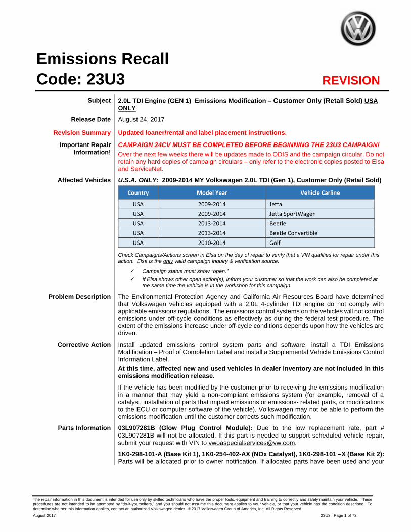
– LOANER/RENTAL MUST BE CLAIMED ON A SEPARATE LINE –
DO NOT PUT ON CAMPAIGN CLAIM
LOANER/RENTAL Claim Type: A1A
Service #: CU01
Damage Code: 0010
Removed Part : MOB
Outside LO Number : CU010000
DO NOT PUT LOANER/RENTAL ON CAMPAIGN CLAIM

The repair information in this document is intended for use only by skilled technicians who have the proper tools, equipment and training to correctly and safely maintain your vehicle. These procedures are not intended to be attempted by “do-it-yourselfers,” and you should not assume this document applies to your vehicle, or that your vehicle has the condition described. To determine whether this information applies, contact an authorized Volkswagen dealer. 2017 Volkswagen Group of America, Inc. All Rights Reserved.
August 2017 23U3 Page 5 of 73
Campaign Work Procedure 23U3 Emissions Recall
At this time, affected new and used vehicles in dealer inventory are not included in this emissions modification release.
NOTE
Damages resulting from improper repair or failure to follow these work instructions are the dealer’s responsibility and are not eligible for reimbursement under this action.
Required Parts
Criteria Quantity Part Number Part Description
01
1 1K0 298 101 A Base Kit I
1 1K0 254 402 AX NOx Catalyst
1 1K0 298 101 X Base Kit II (Criteria 01 - MY 2009 only)
1 (if required) 03L 907 281 B Glow Plug Control Module (Criteria 01 - MY 2009 only)
1 03L 010 005 G Vehicle Emissions Control Information Label
1 Camp TDI 2016 1A TDI Emissions Modification Label (MY 2009 only)
Criteria Quantity Part Number Part Description
02
1 1K0 298 101 A Base Kit I
1 1K0 254 402 AX NOx Catalyst
1 03L 010 005 G Vehicle Emissions Control Information Label
1 Camp TDI 2016 1B TDI Emissions Modification Label (MY 2010-2014)
Labels are sent free of charge. Additional shipments will be released based on the volume of completed repairs claimed through SAGA. The parts will not be available for order through the website at this time. For any additional inquiries contact [email protected].
The repair information in this document is intended for use only by skilled technicians who have the proper tools, equipment and training to correctly and safely maintain your vehicle. These procedures are not intended to be attempted by “do-it-yourselfers,” and you should not assume this document applies to your vehicle, or that your vehicle has the condition described. To determine whether this information applies, contact an authorized Volkswagen dealer. 2017 Volkswagen Group of America, Inc. All Rights Reserved.
August 2017 23U3 Page 6 of 73
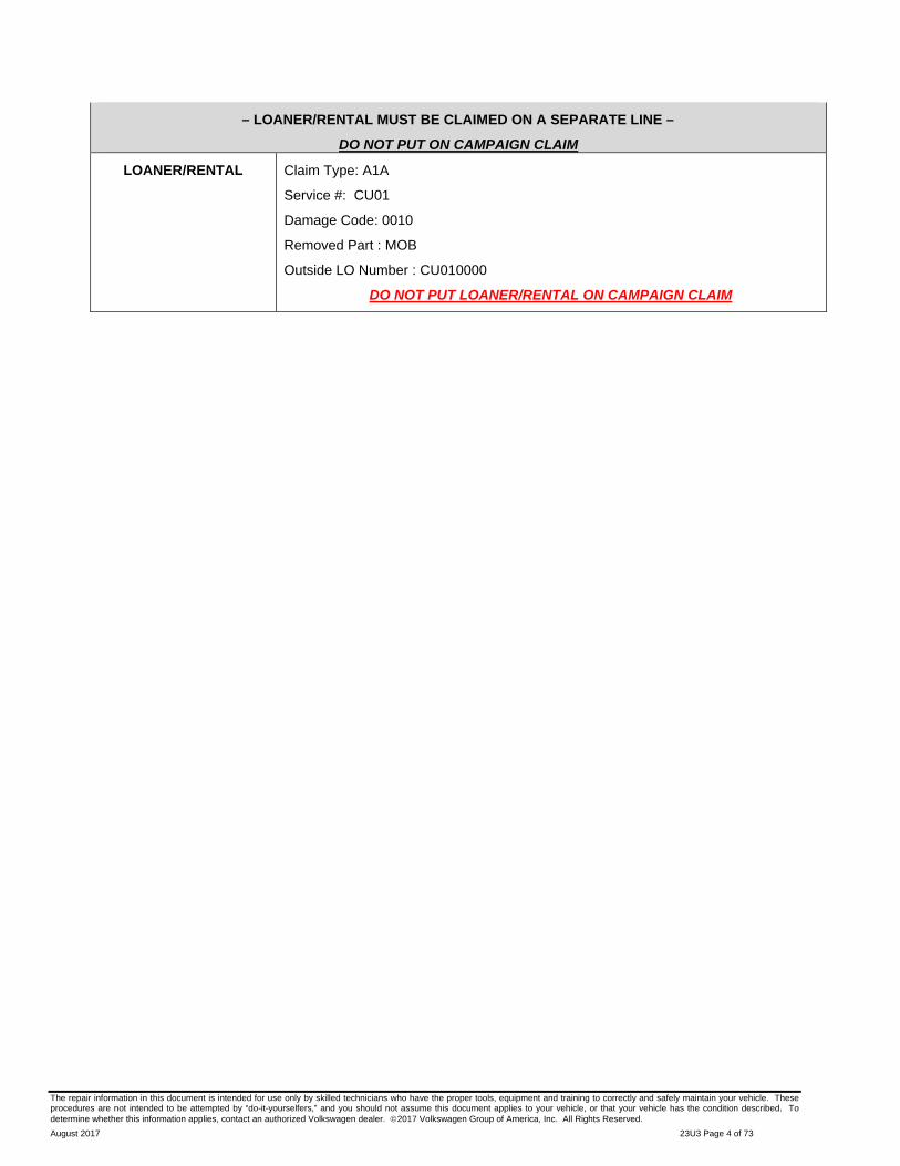
Required Tools
VAS6150X – Diagnostic
Tester (or equivalent)
VAS5054A – Remote Diagnosis Head (or
equivalent)
GRX3000VAS – Battery
Tester/Charger (or equivalent)
Service Modification Validation Web App
tdi-inform.track360.com
TIP
This web application is compatible with desktops, laptops, Apple and Android mobile devices running the most current versions of FireFox, Chrome, Safari, or Explorer as well as iOS 9+ on iPads and iPhones.
NOTE
RISK of Non-payment!
Not using the IN-FORM tool to document and validate the modification will stop the processing of payment for your dealership even if the modification has been completed.
Socket 22mm –T10491–
Torque wrench -V.A.G 1331- (or equivalent)
Torque wrench -V.A.G 1332- (or equivalent)
Locating pins -T10096-

The repair information in this document is intended for use only by skilled technicians who have the proper tools, equipment and training to correctly and safely maintain your vehicle. These procedures are not intended to be attempted by “do-it-yourselfers,” and you should not assume this document applies to your vehicle, or that your vehicle has the condition described. To determine whether this information applies, contact an authorized Volkswagen dealer. 2017 Volkswagen Group of America, Inc. All Rights Reserved.
August 2017 23U3 Page 7 of 73
Hose clamp pliers -VAS 6362- (or equivalent)
Engine and
gearbox jack -VAS 6931-
Transportation lock for flexible joint -T10404-
Tool set -T10395 A-
-3346- Note: 2 Spindles 3346/2 with nuts 3346/3
from assembly tool -3346-
VAS6254 – Chain Pipe Cutter (or
equivalent)
Emissions Modification Instructions
Section A - Check for Previous Emissions Modification
TIP
If the correct TDI Emissions Modification Label is present, no further work is required.
Criteria 01, 2009 MY vehicles: CAMP TDI 2016_1A
Criteria 02, 2010-2014 MY vehicles: CAMP TDI 2016_1B
Enter the VIN in Elsa and proceed to the “Campaign/Action” screen.
TIP
On the date of repair, print this screen and keep a copy with the repair order.
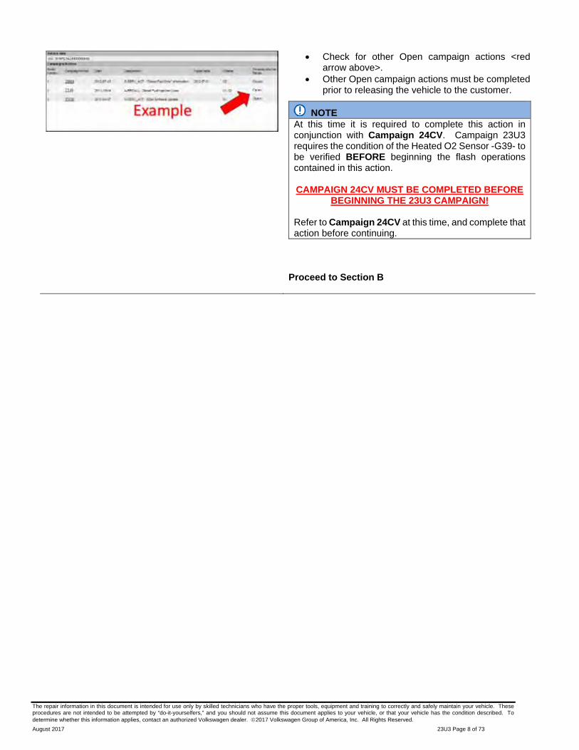
Confirm the Campaign/Action is open <arrow 1>. If the status is closed, no further work is required.
Note the Applicable Criteria ID <arrow 2> for use in determining the correct work to be done and corresponding parts associated.
The repair information in this document is intended for use only by skilled technicians who have the proper tools, equipment and training to correctly and safely maintain your vehicle. These procedures are not intended to be attempted by “do-it-yourselfers,” and you should not assume this document applies to your vehicle, or that your vehicle has the condition described. To determine whether this information applies, contact an authorized Volkswagen dealer. 2017 Volkswagen Group of America, Inc. All Rights Reserved.
August 2017 23U3 Page 8 of 73
Check for other Open campaign actions <red arrow above>.
Other Open campaign actions must be completed prior to releasing the vehicle to the customer.
NOTE At this time it is required to complete this action in conjunction with Campaign 24CV. Campaign 23U3 requires the condition of the Heated O2 Sensor -G39- to be verified BEFORE beginning the flash operations contained in this action. CAMPAIGN 24CV MUST BE COMPLETED BEFORE
BEGINNING THE 23U3 CAMPAIGN!
Refer to Campaign 24CV at this time, and complete that action before continuing.
Proceed to Section B

The repair information in this document is intended for use only by skilled technicians who have the proper tools, equipment and training to correctly and safely maintain your vehicle. These procedures are not intended to be attempted by “do-it-yourselfers,” and you should not assume this document applies to your vehicle, or that your vehicle has the condition described. To determine whether this information applies, contact an authorized Volkswagen dealer. 2017 Volkswagen Group of America, Inc. All Rights Reserved.
August 2017 23U3 Page 9 of 73
Section B – Check for Service Initiation
NOTE
RISK of Non-payment!
Not using the IN-FORM tool to document and validate the modification will stop the processing of payment for your dealership even if the modification has been completed.
Look for the image below to indicate labor operations, parts, or labeling that requires IN-FORM tool image documentation.
NOTE
RISK of Non-payment!
Ensure that the “check mark” <arrow> is present prior to beginning any work.
Ensure the Service Initiation Form has a “check mark” <arrow>.
o If the Service Initiation Form does not have a “check mark” <arrow>, immediately contact your Service Consultant to complete the initiation.
o If “check mark” <arrow> is present, initiate Service Modification Documentation Form and continue work.
DO NOT proceed with any work unless you can initiate the Service Modification Documentation Form. Proceed to Section C

The repair information in this document is intended for use only by skilled technicians who have the proper tools, equipment and training to correctly and safely maintain your vehicle. These procedures are not intended to be attempted by “do-it-yourselfers,” and you should not assume this document applies to your vehicle, or that your vehicle has the condition described. To determine whether this information applies, contact an authorized Volkswagen dealer. 2017 Volkswagen Group of America, Inc. All Rights Reserved.
August 2017 23U3 Page 10 of 73
Section C – Check for Pre-existing conditions, Vehicle Modifications, and MIL light on
Perform a visual inspection of the intake, exhaust, and emissions systems.
o If the visual inspection of the intake, exhaust, or emissions equipment reveals damage or concerns, STOP, create a VTA ticket and contact the Volkswagen Technicians Helpline.
o If the visual inspection of the intake, exhaust, or emissions equipment reveals no damage or concerns, continue the work procedure.
Check for vehicle modifications from original equipment.
o If vehicle modifications from original equipment related to emissions components are found, STOP, create a VTA ticket and contact the Volkswagen Technicians Helpline.
o If vehicle modifications from original equipment related to emissions components are not found, continue the work procedure.

The repair information in this document is intended for use only by skilled technicians who have the proper tools, equipment and training to correctly and safely maintain your vehicle. These procedures are not intended to be attempted by “do-it-yourselfers,” and you should not assume this document applies to your vehicle, or that your vehicle has the condition described. To determine whether this information applies, contact an authorized Volkswagen dealer. 2017 Volkswagen Group of America, Inc. All Rights Reserved.
August 2017 23U3 Page 11 of 73
Check for illumination of the MIL <arrow>.
o If MIL is illuminated, STOP, create a VTA ticket and contact the Volkswagen Technicians Helpline.
o If MIL is not illuminated, continue the work procedure.
TIP
VTA cases regarding MIL ON conditions require a GFF diagnostic log to be uploaded at the time of first contact.
The purpose for this step is to document vehicle condition prior to initiation of this action and does not authorize the repair of any pre-existing conditions.
NOTE At this time it is required to complete this action in conjunction with Campaign 24CV. Campaign 23U3 requires the condition of the Heated O2 Sensor -G39- to be verified BEFORE beginning the flash operations contained in this action. CAMPAIGN 24CV MUST BE COMPLETED BEFORE
BEGINNING THE 23U3 CAMPAIGN!
Refer to Campaign 24CV at this time, and complete that action before continuing.
Proceed to Section D for Criteria 02 – (MY 2010-2014) Proceed to Section E for Criteria 01 – (MY 2009)

The repair information in this document is intended for use only by skilled technicians who have the proper tools, equipment and training to correctly and safely maintain your vehicle. These procedures are not intended to be attempted by “do-it-yourselfers,” and you should not assume this document applies to your vehicle, or that your vehicle has the condition described. To determine whether this information applies, contact an authorized Volkswagen dealer. 2017 Volkswagen Group of America, Inc. All Rights Reserved.
August 2017 23U3 Page 12 of 73
Section D – Emissions Kit Installation (Criteria 02 – MY 2010-2014 ONLY)
NOTE
At this time, verify that Campaign 24CV has been completed. Campaign 24CV must be completed before continuing with this repair procedure.
THE 24CV CAMPAIGN MUST BE COMPLETED BEFORE BEGINNING THIS CAMPAIGN!
TIP
Section D addresses vehicles built with a two-piece Diesel Particulate Filter/Lean NOx trap exhaust system. This system was introduced starting in MY 2010. For vehicles built with a one-piece system, the DPF must be replaced as there is no connection on the original components.
Begin with Section E for vehicles having Criteria 01, with a one-piece DPF/Lean NOx trap system (for Model Year 2009 vehicles).
Open hood.
Raise vehicle on hoist.
Unscrew nuts <arrows> and pull underbody cladding down slightly.
TIP
A wedge could be placed between vehicle body and cladding to allow more work space.

The repair information in this document is intended for use only by skilled technicians who have the proper tools, equipment and training to correctly and safely maintain your vehicle. These procedures are not intended to be attempted by “do-it-yourselfers,” and you should not assume this document applies to your vehicle, or that your vehicle has the condition described. To determine whether this information applies, contact an authorized Volkswagen dealer. 2017 Volkswagen Group of America, Inc. All Rights Reserved.
August 2017 23U3 Page 13 of 73
Disconnect »brown« connector for oxygen sensor after catalytic converter -G130- <2>. Remove plug from retainer.
Open fasteners for heat shield and pull connector <1> off exhaust door control unit -J883- and thread wiring out of retainers <arrows>.
TIP
Take a photo of this area now for help with harness routing during reinstallation later.
Loosen clamps <1 and 2> and remove NOx storage catalytic converter together with exhaust door control unit -J883-.

The repair information in this document is intended for use only by skilled technicians who have the proper tools, equipment and training to correctly and safely maintain your vehicle. These procedures are not intended to be attempted by “do-it-yourselfers,” and you should not assume this document applies to your vehicle, or that your vehicle has the condition described. To determine whether this information applies, contact an authorized Volkswagen dealer. 2017 Volkswagen Group of America, Inc. All Rights Reserved.
August 2017 23U3 Page 14 of 73
Screw new oxygen sensor after catalytic converter -G130- <2> into new NOx storage catalytic converter <1> and tighten to 52 Nm using socket, 22 mm -T10491-.
Set new exhaust door control unit -J883- <5> with new seal <3> on NOx storage catalytic converter <1>. Note notches <arrows>.
NOTE
Renew all clamps and seals. The clamps before and after the exhaust door control unit are narrower than the clamp connecting the particulate filter to the NOx storage catalytic converter. Ensure that they are correctly allocated.
Position clamp 1K0 253 725 B <4> and tighten to 7 Nm.
Place NOx storage catalytic converter together with exhaust door control unit -J883- with new seals in installation position. Note notches at rear connection.
Position all clamps <1> so that they will not collide with underbody.
NOTE
Install clamps on the exhaust pipe before installing pipe into vehicle. Do not attempt to stretch clamps around pipe once installed, or clamps may fail to seal properly.
The repair information in this document is intended for use only by skilled technicians who have the proper tools, equipment and training to correctly and safely maintain your vehicle. These procedures are not intended to be attempted by “do-it-yourselfers,” and you should not assume this document applies to your vehicle, or that your vehicle has the condition described. To determine whether this information applies, contact an authorized Volkswagen dealer. 2017 Volkswagen Group of America, Inc. All Rights Reserved.
August 2017 23U3 Page 15 of 73
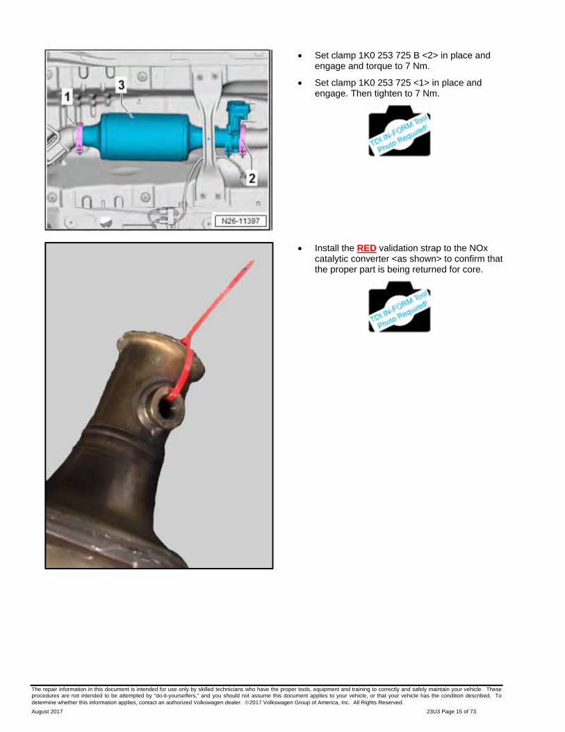
Set clamp 1K0 253 725 B <2> in place and engage and torque to 7 Nm.
Set clamp 1K0 253 725 <1> in place and engage. Then tighten to 7 Nm.
Install the RED validation strap to the NOx catalytic converter <as shown> to confirm that the proper part is being returned for core.

The repair information in this document is intended for use only by skilled technicians who have the proper tools, equipment and training to correctly and safely maintain your vehicle. These procedures are not intended to be attempted by “do-it-yourselfers,” and you should not assume this document applies to your vehicle, or that your vehicle has the condition described. To determine whether this information applies, contact an authorized Volkswagen dealer. 2017 Volkswagen Group of America, Inc. All Rights Reserved.
August 2017 23U3 Page 16 of 73
Connect »brown« connector for oxygen sensor after catalytic converter -G130- <2> and attach to bracket.
Push connector <1> onto exhaust door control unit. Secure lines in retainers <arrows>.
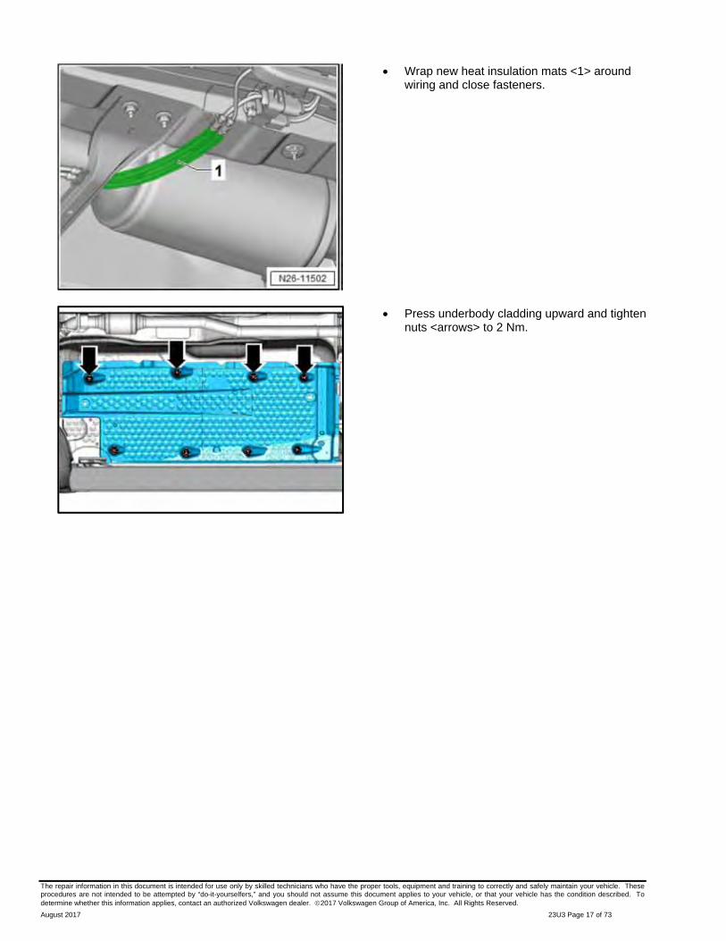
Wrap new heat insulation mats <1> around wiring and close fasteners.
Place wires <2> in clips <3 and 4>.
The repair information in this document is intended for use only by skilled technicians who have the proper tools, equipment and training to correctly and safely maintain your vehicle. These procedures are not intended to be attempted by “do-it-yourselfers,” and you should not assume this document applies to your vehicle, or that your vehicle has the condition described. To determine whether this information applies, contact an authorized Volkswagen dealer. 2017 Volkswagen Group of America, Inc. All Rights Reserved.
August 2017 23U3 Page 17 of 73
Wrap new heat insulation mats <1> around wiring and close fasteners.
Press underbody cladding upward and tighten nuts <arrows> to 2 Nm.

The repair information in this document is intended for use only by skilled technicians who have the proper tools, equipment and training to correctly and safely maintain your vehicle. These procedures are not intended to be attempted by “do-it-yourselfers,” and you should not assume this document applies to your vehicle, or that your vehicle has the condition described. To determine whether this information applies, contact an authorized Volkswagen dealer. 2017 Volkswagen Group of America, Inc. All Rights Reserved.
August 2017 23U3 Page 18 of 73
Remove bolts <2 and 3>.
Pull noise insulation <1> back, out of front bumper cover <4>.
Remove nut <2> from exhaust gas recirculation filter <1> from below using 13 mm ratchet box wrench (e. g. Snap-on OEXRM13).
Wrap tape around the tip of a long screwdriver (e.g. Snap-on SDD162 No.2).

The repair information in this document is intended for use only by skilled technicians who have the proper tools, equipment and training to correctly and safely maintain your vehicle. These procedures are not intended to be attempted by “do-it-yourselfers,” and you should not assume this document applies to your vehicle, or that your vehicle has the condition described. To determine whether this information applies, contact an authorized Volkswagen dealer. 2017 Volkswagen Group of America, Inc. All Rights Reserved.
August 2017 23U3 Page 19 of 73
Apply screwdriver <2> on side of nut <1> and unscrew nut while simultaneously pressing up on nut.
Open clamp <3> and remove it.
Remove bolts <1> and remove exhaust gas recirculation filter <2>.
Set new exhaust gas recirculation filter <2> with new seals in place, screw in bolts <1> and tighten to 9 Nm.
Position clamp <3> and tighten to 3.5 Nm.
Description Part number EGR Filter 1K0 253 120 B Seal 03G 131 547 H Seal 1K0 253 115 AG Clamp 1K0 253 725 F
The repair information in this document is intended for use only by skilled technicians who have the proper tools, equipment and training to correctly and safely maintain your vehicle. These procedures are not intended to be attempted by “do-it-yourselfers,” and you should not assume this document applies to your vehicle, or that your vehicle has the condition described. To determine whether this information applies, contact an authorized Volkswagen dealer. 2017 Volkswagen Group of America, Inc. All Rights Reserved.
August 2017 23U3 Page 20 of 73
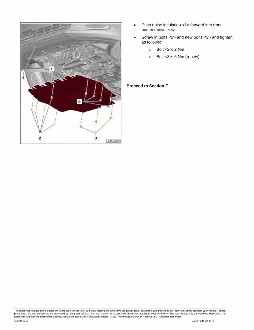
Push noise insulation <1> forward into front bumper cover <4>.
Screw in bolts <2> and new bolts <3> and tighten as follows:
o Bolt <2>: 2 Nm
o Bolt <3>: 6 Nm (renew)
Proceed to Section F
The repair information in this document is intended for use only by skilled technicians who have the proper tools, equipment and training to correctly and safely maintain your vehicle. These procedures are not intended to be attempted by “do-it-yourselfers,” and you should not assume this document applies to your vehicle, or that your vehicle has the condition described. To determine whether this information applies, contact an authorized Volkswagen dealer. 2017 Volkswagen Group of America, Inc. All Rights Reserved.
August 2017 23U3 Page 21 of 73
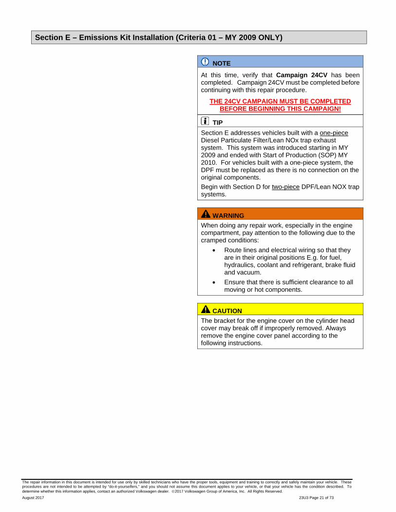
Section E – Emissions Kit Installation (Criteria 01 – MY 2009 ONLY)
NOTE
At this time, verify that Campaign 24CV has been completed. Campaign 24CV must be completed before continuing with this repair procedure.
THE 24CV CAMPAIGN MUST BE COMPLETED BEFORE BEGINNING THIS CAMPAIGN!
TIP
Section E addresses vehicles built with a one-piece Diesel Particulate Filter/Lean NOx trap exhaust system. This system was introduced starting in MY 2009 and ended with Start of Production (SOP) MY 2010. For vehicles built with a one-piece system, the DPF must be replaced as there is no connection on the original components.
Begin with Section D for two-piece DPF/Lean NOX trap systems.
WARNING
When doing any repair work, especially in the engine compartment, pay attention to the following due to the cramped conditions:
Route lines and electrical wiring so that they are in their original positions E.g. for fuel, hydraulics, coolant and refrigerant, brake fluid and vacuum.
Ensure that there is sufficient clearance to all moving or hot components.
CAUTION
The bracket for the engine cover on the cylinder head cover may break off if improperly removed. Always remove the engine cover panel according to the following instructions.

The repair information in this document is intended for use only by skilled technicians who have the proper tools, equipment and training to correctly and safely maintain your vehicle. These procedures are not intended to be attempted by “do-it-yourselfers,” and you should not assume this document applies to your vehicle, or that your vehicle has the condition described. To determine whether this information applies, contact an authorized Volkswagen dealer. 2017 Volkswagen Group of America, Inc. All Rights Reserved.
August 2017 23U3 Page 22 of 73
Pull engine cover up out of fastening elements near <arrows> in order shown. To do this, grip as far as possible beneath engine cover.
Disconnect »orange« connector for exhaust gas temperature sender 2 -G448- <1> and »black« connector for oxygen sensor -G39- <2> on plenum chamber bulkhead.
Remove wiring <3> from retainer and move clear.
TIP Take a photo of this area now for help with harness routing during reinstallation later.
Disconnect »brown« connector for exhaust gas temperature sender 3 -G495- <2> (secured behind bracket).
Thread lines out of brackets <1> on plenum chamber bulkhead and on turbocharger.
The repair information in this document is intended for use only by skilled technicians who have the proper tools, equipment and training to correctly and safely maintain your vehicle. These procedures are not intended to be attempted by “do-it-yourselfers,” and you should not assume this document applies to your vehicle, or that your vehicle has the condition described. To determine whether this information applies, contact an authorized Volkswagen dealer. 2017 Volkswagen Group of America, Inc. All Rights Reserved.
August 2017 23U3 Page 23 of 73
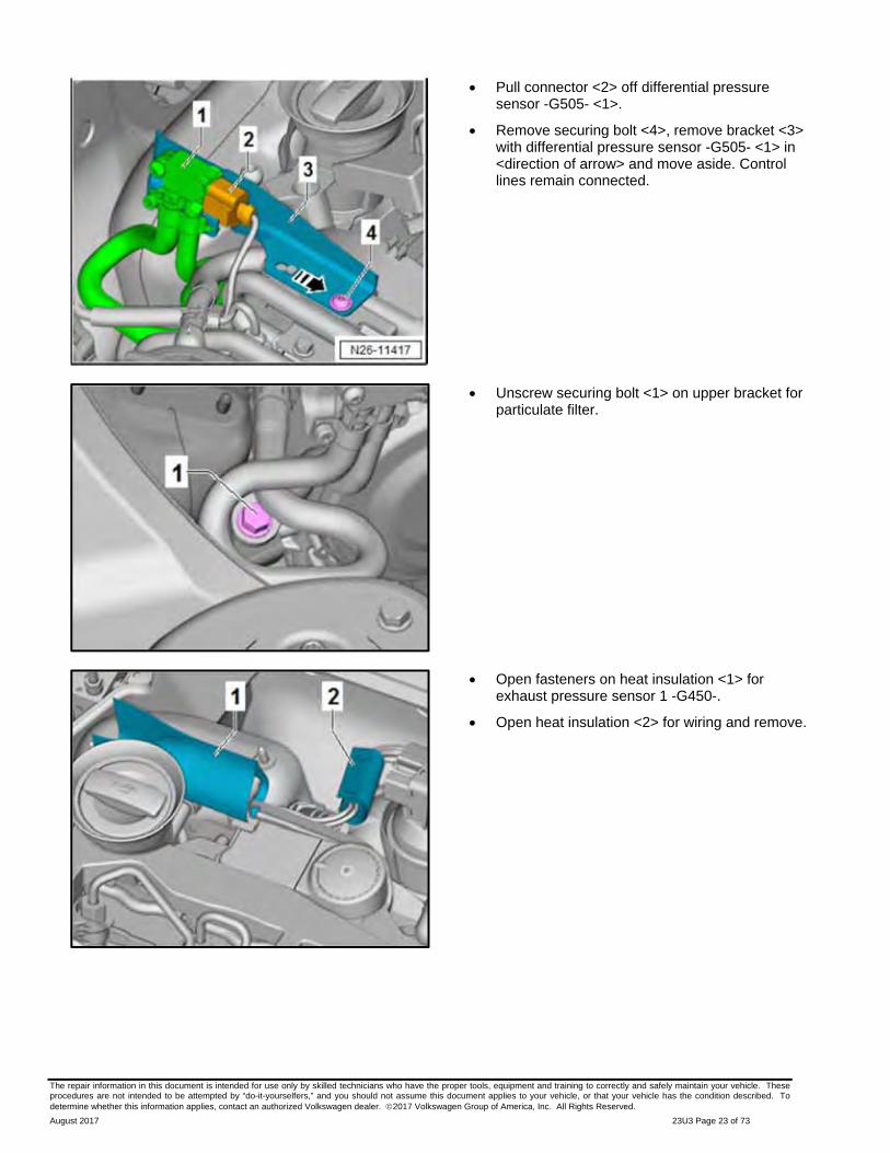
Pull connector <2> off differential pressure sensor -G505- <1>.
Remove securing bolt <4>, remove bracket <3> with differential pressure sensor -G505- <1> in <direction of arrow> and move aside. Control lines remain connected.
Unscrew securing bolt <1> on upper bracket for particulate filter.
Open fasteners on heat insulation <1> for exhaust pressure sensor 1 -G450-.
Open heat insulation <2> for wiring and remove.
The repair information in this document is intended for use only by skilled technicians who have the proper tools, equipment and training to correctly and safely maintain your vehicle. These procedures are not intended to be attempted by “do-it-yourselfers,” and you should not assume this document applies to your vehicle, or that your vehicle has the condition described. To determine whether this information applies, contact an authorized Volkswagen dealer. 2017 Volkswagen Group of America, Inc. All Rights Reserved.
August 2017 23U3 Page 24 of 73
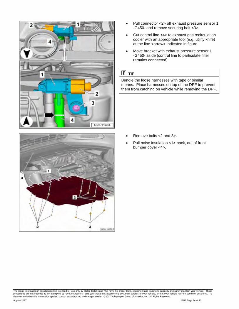
Pull connector <2> off exhaust pressure sensor 1 -G450- and remove securing bolt <3>.
Cut control line <4> to exhaust gas recirculation cooler with an appropriate tool (e.g. utility knife) at the line <arrow> indicated in figure.
Move bracket with exhaust pressure sensor 1 -G450- aside (control line to particulate filter remains connected).
TIP
Bundle the loose harnesses with tape or similar means. Place harnesses on top of the DPF to prevent them from catching on vehicle while removing the DPF.
Remove bolts <2 and 3>.
Pull noise insulation <1> back, out of front bumper cover <4>.

The repair information in this document is intended for use only by skilled technicians who have the proper tools, equipment and training to correctly and safely maintain your vehicle. These procedures are not intended to be attempted by “do-it-yourselfers,” and you should not assume this document applies to your vehicle, or that your vehicle has the condition described. To determine whether this information applies, contact an authorized Volkswagen dealer. 2017 Volkswagen Group of America, Inc. All Rights Reserved.
August 2017 23U3 Page 25 of 73
Unscrew bolts <1> and remove heat shield for right drive shaft.
NOTE
Unscrew securing nuts above bracket <2> with ratchet wrench -T10384-. In some cases, the bracket cannot be removed until the particulate filter has been detached.
Remove nuts <2 and 3> and remove lower bracket for particulate filter <1>.
Open clamp <3> and remove it.
NOTE
The exhaust gas recirculation filter <2> is removed after the particulate filter has been removed.

The repair information in this document is intended for use only by skilled technicians who have the proper tools, equipment and training to correctly and safely maintain your vehicle. These procedures are not intended to be attempted by “do-it-yourselfers,” and you should not assume this document applies to your vehicle, or that your vehicle has the condition described. To determine whether this information applies, contact an authorized Volkswagen dealer. 2017 Volkswagen Group of America, Inc. All Rights Reserved.
August 2017 23U3 Page 26 of 73
NOTE
Position of clamp <1> may vary. If necessary, use 5 mm bit with ball head (e.g. T10058).
Loosen and remove clamp <1> connecting turbocharger and particulate filter.
Unscrew nuts <arrows> and pull underbody cladding on right down slightly.
Disconnect »brown« connector for oxygen sensor after catalytic converter -G130- <2>. Remove plug from retainer.
Open fasteners on heat shield, pull connector <1> off exhaust door control unit -J883- and thread wiring out of retainers <arrows>.

The repair information in this document is intended for use only by skilled technicians who have the proper tools, equipment and training to correctly and safely maintain your vehicle. These procedures are not intended to be attempted by “do-it-yourselfers,” and you should not assume this document applies to your vehicle, or that your vehicle has the condition described. To determine whether this information applies, contact an authorized Volkswagen dealer. 2017 Volkswagen Group of America, Inc. All Rights Reserved.
August 2017 23U3 Page 27 of 73
Disconnect connector <1>. Take electrical wire from exhaust gas temperature sensor 4 -G648- <2> on heat shield out of clip <arrow> and bracket and move to side.
Remove bolts <arrows> from exhaust system bracket on subframe.
Remove bolts <arrows> and remove right drive shaft from transmission. Rest drive shaft on front axle.
The repair information in this document is intended for use only by skilled technicians who have the proper tools, equipment and training to correctly and safely maintain your vehicle. These procedures are not intended to be attempted by “do-it-yourselfers,” and you should not assume this document applies to your vehicle, or that your vehicle has the condition described. To determine whether this information applies, contact an authorized Volkswagen dealer. 2017 Volkswagen Group of America, Inc. All Rights Reserved.
August 2017 23U3 Page 28 of 73
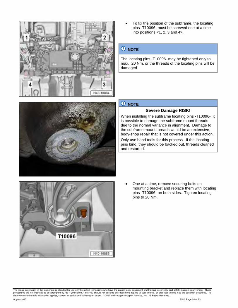
To fix the position of the subframe, the locating pins -T10096- must be screwed one at a time into positions <1, 2, 3 and 4>.
NOTE
The locating pins -T10096- may be tightened only to max. 20 Nm, or the threads of the locating pins will be damaged.
NOTE
Severe Damage RISK! When installing the subframe locating pins -T10096-, it is possible to damage the subframe mount threads due to the normal variance in alignment. Damage to the subframe mount threads would be an extensive, body-shop repair that is not covered under this action.
Only use hand tools for this process. If the locating pins bind, they should be backed out, threads cleaned and restarted.
One at a time, remove securing bolts on mounting bracket and replace them with locating pins -T10096- on both sides. Tighten locating pins to 20 Nm.

The repair information in this document is intended for use only by skilled technicians who have the proper tools, equipment and training to correctly and safely maintain your vehicle. These procedures are not intended to be attempted by “do-it-yourselfers,” and you should not assume this document applies to your vehicle, or that your vehicle has the condition described. To determine whether this information applies, contact an authorized Volkswagen dealer. 2017 Volkswagen Group of America, Inc. All Rights Reserved.
August 2017 23U3 Page 29 of 73
One at a time, replace bolts in brackets with locating pins -T10096-. Tighten locating pins to 20 Nm.
TIP
The position of the front axle is now fixed.
Turn steering wheel to straight-ahead position and remove ignition key to engage steering wheel lock.
If the vehicle has the keyless locking and starting system “Keyless Access”, switch off ignition and open driver door to engage steering wheel lock.
Remove bolts <1> and remove footwell trim <2>.
CAUTION Never perform the following actions if the U-joint has been separated from the electromechanical steering mechanism: Switching ignition on Turning steering mechanism Turning steering column These points must always be complied with because these actions can cause irreparable damage to the clock spring or other items that are not covered under this action.
Remove bolt <arrow> from U-joint <1> and pull off U-joint in <direction of arrow>.

The repair information in this document is intended for use only by skilled technicians who have the proper tools, equipment and training to correctly and safely maintain your vehicle. These procedures are not intended to be attempted by “do-it-yourselfers,” and you should not assume this document applies to your vehicle, or that your vehicle has the condition described. To determine whether this information applies, contact an authorized Volkswagen dealer. 2017 Volkswagen Group of America, Inc. All Rights Reserved.
August 2017 23U3 Page 30 of 73
Remove bolts <2 and 3> for pendulum support <1> from gearbox.
Unscrew hexagon nut <1> on left and right from coupling rod <3>.
Pull coupling rod <3> on the left and right out of anti-roll bar <2>.
TIP
Apply penetrating oil to the hexagon <1> nut to aid in removal.
Place engine and gearbox jack -VAS 6931- <1> under subframe.

The repair information in this document is intended for use only by skilled technicians who have the proper tools, equipment and training to correctly and safely maintain your vehicle. These procedures are not intended to be attempted by “do-it-yourselfers,” and you should not assume this document applies to your vehicle, or that your vehicle has the condition described. To determine whether this information applies, contact an authorized Volkswagen dealer. 2017 Volkswagen Group of America, Inc. All Rights Reserved.
August 2017 23U3 Page 31 of 73
Screw nuts -3346/3- <2> by hand as shown onto spindles -3346/2- <1> to end of thread as shown.
NOTE
For clarity of illustration, the following steps are shown without the engine and gearbox jack.
Unscrew bolts <1 and 2>.
Screw in spindles 3346/2 by hand until distance <a> equals 90 mm.

The repair information in this document is intended for use only by skilled technicians who have the proper tools, equipment and training to correctly and safely maintain your vehicle. These procedures are not intended to be attempted by “do-it-yourselfers,” and you should not assume this document applies to your vehicle, or that your vehicle has the condition described. To determine whether this information applies, contact an authorized Volkswagen dealer. 2017 Volkswagen Group of America, Inc. All Rights Reserved.
August 2017 23U3 Page 32 of 73
Lower subframe about 5cm and remove bolt <1> on the wire harness bracket for steering gear.
Lower the engine and gearbox jack -VAS 6931- completely and remove it from work area.
TIP
The subframe is now supported by spindles 3346/2.
Remove hexagon nuts <2> from front tunnel cross-piece <1> and remove tunnel cross-piece.
Remove securing clamp between NOx storage catalytic converter and exhaust door control unit -J883-.
With the help of a second technician, remove particulate filter. Do this by turning the particulate filter <1> out of center tunnel. Note electrical wiring and components when doing this.
The repair information in this document is intended for use only by skilled technicians who have the proper tools, equipment and training to correctly and safely maintain your vehicle. These procedures are not intended to be attempted by “do-it-yourselfers,” and you should not assume this document applies to your vehicle, or that your vehicle has the condition described. To determine whether this information applies, contact an authorized Volkswagen dealer. 2017 Volkswagen Group of America, Inc. All Rights Reserved.
August 2017 23U3 Page 33 of 73
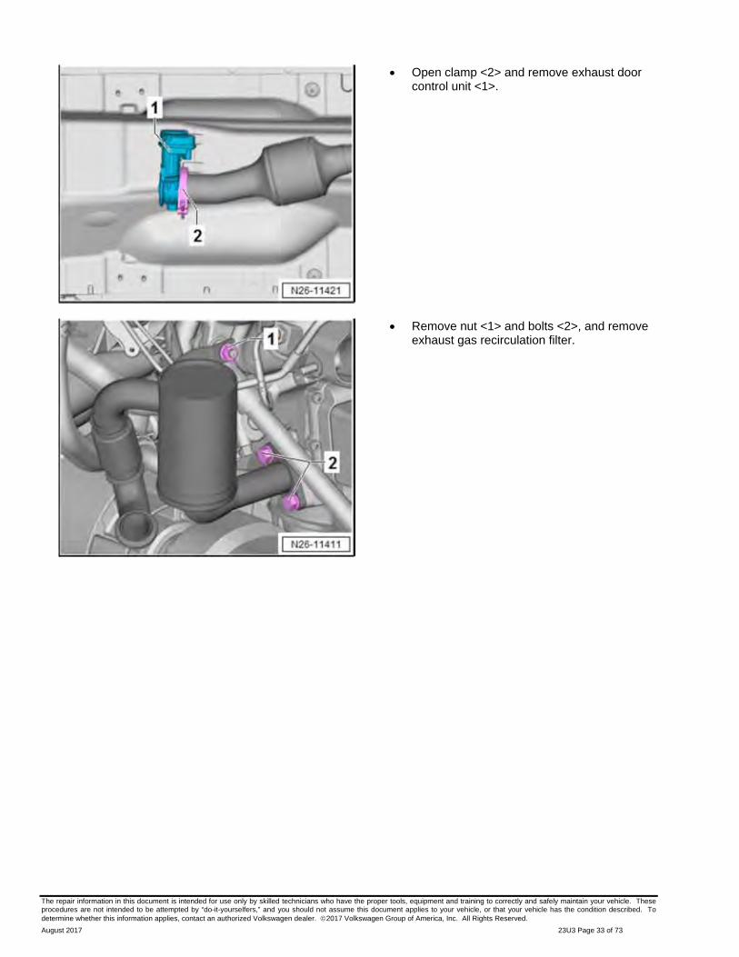
Open clamp <2> and remove exhaust door control unit <1>.
Remove nut <1> and bolts <2>, and remove exhaust gas recirculation filter.

The repair information in this document is intended for use only by skilled technicians who have the proper tools, equipment and training to correctly and safely maintain your vehicle. These procedures are not intended to be attempted by “do-it-yourselfers,” and you should not assume this document applies to your vehicle, or that your vehicle has the condition described. To determine whether this information applies, contact an authorized Volkswagen dealer. 2017 Volkswagen Group of America, Inc. All Rights Reserved.
August 2017 23U3 Page 34 of 73
TIP Before the installation of the newly assembled filter, place the new and old assembly side-by-side for comparison.
Assemble particulate filter as follows before installation:
CAUTION
If transportation lock was not included among items supplied, ensure that flexible joint is fixed with transportation lock -T10404- to prevent damage to the flex pipe.
1 - Position control line and screw in union nut hand-tight.
2 - Position retainer for control line, screw in bolt, tighten to 9 Nm and then tighten union nut to 45 Nm.
3 - Attach connecting hoses from differential pressure sensor -G505- as shown and secure with spring clamps.
4 - Screw in oxygen sensor -G39- and tighten to 52 Nm.
5 - Screw in exhaust gas temperature sensor 2 -G448- (connector color: orange, angled 110°) and tighten to 45 Nm.
6 - Screw in exhaust gas temperature sensor 3 -G495- (connector color: brown) and tighten to 45 Nm.
7 - Screw in exhaust gas temperature sensor 4 -G648- (connector color: beige, angled 90°) and tighten to 45 Nm.
8 - Set heat shield in position and check that it is properly seated <arrows>. Tighten nuts to 10 Nm.
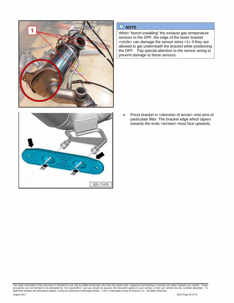
NOTE
When installing the exhaust gas temperature sensors to the DPF, it is possible to install the sensors <1> in the wrong locations. Sensors installed in the wrong positions will not function properly. Pay attention to the sensor color coding <circle> when installing sensors into the DPF.
The repair information in this document is intended for use only by skilled technicians who have the proper tools, equipment and training to correctly and safely maintain your vehicle. These procedures are not intended to be attempted by “do-it-yourselfers,” and you should not assume this document applies to your vehicle, or that your vehicle has the condition described. To determine whether this information applies, contact an authorized Volkswagen dealer. 2017 Volkswagen Group of America, Inc. All Rights Reserved.
August 2017 23U3 Page 35 of 73
NOTE
When “bench-installing” the exhaust gas temperature sensors to the DPF, the edge of the lower bracket <circle> can damage the sensor wires <1> if they are allowed to get underneath the bracket while positioning the DPF. Pay special attention to the sensor wiring to prevent damage to these sensors.
Press bracket in <direction of arrow> onto pins of particulate filter. The bracket edge which tapers towards the ends <arrows> must face upwards.
The repair information in this document is intended for use only by skilled technicians who have the proper tools, equipment and training to correctly and safely maintain your vehicle. These procedures are not intended to be attempted by “do-it-yourselfers,” and you should not assume this document applies to your vehicle, or that your vehicle has the condition described. To determine whether this information applies, contact an authorized Volkswagen dealer. 2017 Volkswagen Group of America, Inc. All Rights Reserved.
August 2017 23U3 Page 36 of 73
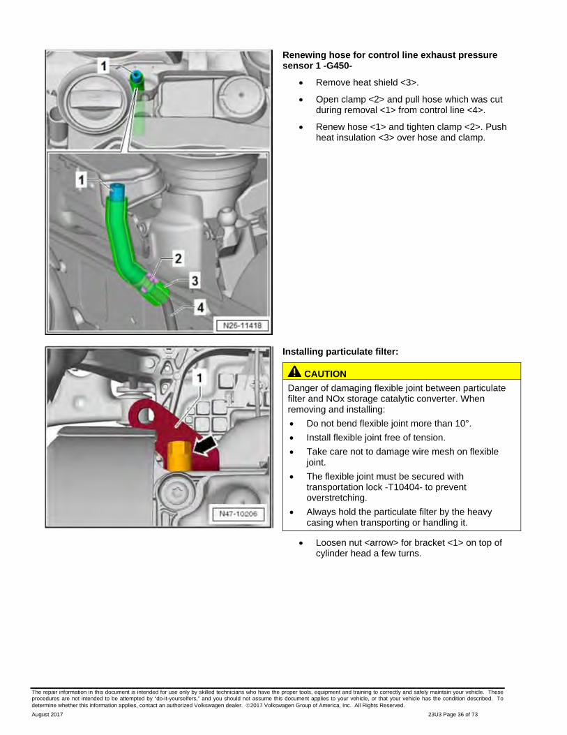
Renewing hose for control line exhaust pressure sensor 1 -G450-
Remove heat shield <3>.
Open clamp <2> and pull hose which was cut during removal <1> from control line <4>.
Renew hose <1> and tighten clamp <2>. Push heat insulation <3> over hose and clamp.
Installing particulate filter:
CAUTION
Danger of damaging flexible joint between particulate filter and NOx storage catalytic converter. When removing and installing:
Do not bend flexible joint more than 10°.
Install flexible joint free of tension.
Take care not to damage wire mesh on flexible joint.
The flexible joint must be secured with transportation lock -T10404- to prevent overstretching.
Always hold the particulate filter by the heavy casing when transporting or handling it.
Loosen nut <arrow> for bracket <1> on top of cylinder head a few turns.

The repair information in this document is intended for use only by skilled technicians who have the proper tools, equipment and training to correctly and safely maintain your vehicle. These procedures are not intended to be attempted by “do-it-yourselfers,” and you should not assume this document applies to your vehicle, or that your vehicle has the condition described. To determine whether this information applies, contact an authorized Volkswagen dealer. 2017 Volkswagen Group of America, Inc. All Rights Reserved.
August 2017 23U3 Page 37 of 73
Secure electrical wiring of both upper exhaust gas temperature sensors (connector colors brown and orange), the heated oxygen sensor and differential pressure sensor -G505- with tape to the top of the heat shield on the particulate filter.
Position new clamp 1K0 253 725 over the intake funnel of the particulate filter. Orient new clamp (positioned downward) to the same clocking as the original clamp.
Move particle filter into installation position by »turning« it into center tunnel. Take care not to damage electrical wiring or components.
Ensure that the transportation lock -T10404- <arrow> is properly seated.
NOTE Unlike the production bracket, the supplied bracket no longer has threaded studs. It must be screwed to the particulate filter using the supplied bolts, and the nuts must be screwed on from below. The ball indentation on the bracket faces the crankcase.
Hold bracket in place and start new bolts for nuts <2> in bracket from above.
Start nuts <3 and 2> by hand a few full turns.

The repair information in this document is intended for use only by skilled technicians who have the proper tools, equipment and training to correctly and safely maintain your vehicle. These procedures are not intended to be attempted by “do-it-yourselfers,” and you should not assume this document applies to your vehicle, or that your vehicle has the condition described. To determine whether this information applies, contact an authorized Volkswagen dealer. 2017 Volkswagen Group of America, Inc. All Rights Reserved.
August 2017 23U3 Page 38 of 73
Installing subframe:
Position engine and gearbox jack -VAS 6931- under subframe.
Raise subframe about 5 cm, screw in bolt <1> on the wire harness bracket for steering gear and tighten to 3 Nm.
Carefully raise subframe to installation position taking locating pins into consideration.
Remove spindles -3346/2-, screw in new bolts (M12 x 110 mm) at positions <1 and 2>, tighten to 70 Nm and turn an additional 90°.

The repair information in this document is intended for use only by skilled technicians who have the proper tools, equipment and training to correctly and safely maintain your vehicle. These procedures are not intended to be attempted by “do-it-yourselfers,” and you should not assume this document applies to your vehicle, or that your vehicle has the condition described. To determine whether this information applies, contact an authorized Volkswagen dealer. 2017 Volkswagen Group of America, Inc. All Rights Reserved.
August 2017 23U3 Page 39 of 73
Remove locating pins one at a time and replace them with new bolts (M12 x 90 mm).
Tighten bolts to 70 Nm, then tighten them an additional 90°.
Take load off engine and gearbox jack -VAS 6931- and remove it from work area.
Guide coupling rods <3> on left and right into anti-roll bar, screw on new hexagon nuts <1> and tighten to 65 Nm.
Screw in new bolts <2 and 3> for pendulum support <1>, tighten them to 50 Nm and then tighten and additional 90°.
The repair information in this document is intended for use only by skilled technicians who have the proper tools, equipment and training to correctly and safely maintain your vehicle. These procedures are not intended to be attempted by “do-it-yourselfers,” and you should not assume this document applies to your vehicle, or that your vehicle has the condition described. To determine whether this information applies, contact an authorized Volkswagen dealer. 2017 Volkswagen Group of America, Inc. All Rights Reserved.
August 2017 23U3 Page 40 of 73
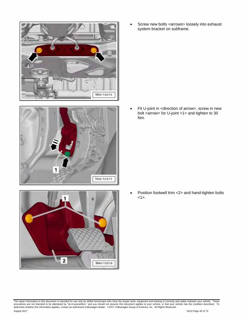
Screw new bolts <arrows> loosely into exhaust system bracket on subframe.
Fit U-joint in <direction of arrow>, screw in new bolt <arrow> for U-joint <1> and tighten to 30 Nm.
Position footwell trim <2> and hand-tighten bolts <1>.
The repair information in this document is intended for use only by skilled technicians who have the proper tools, equipment and training to correctly and safely maintain your vehicle. These procedures are not intended to be attempted by “do-it-yourselfers,” and you should not assume this document applies to your vehicle, or that your vehicle has the condition described. To determine whether this information applies, contact an authorized Volkswagen dealer. 2017 Volkswagen Group of America, Inc. All Rights Reserved.
August 2017 23U3 Page 41 of 73
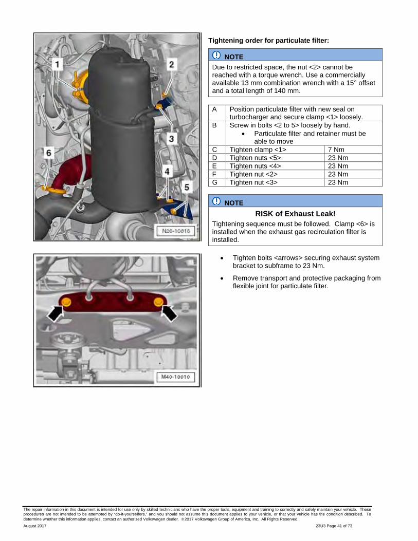
Tightening order for particulate filter:
NOTE
Due to restricted space, the nut <2> cannot be reached with a torque wrench. Use a commercially available 13 mm combination wrench with a 15° offset and a total length of 140 mm.
A Position particulate filter with new seal on
turbocharger and secure clamp <1> loosely. B Screw in bolts <2 to 5> loosely by hand.
Particulate filter and retainer must be able to move
C Tighten clamp <1> 7 Nm D Tighten nuts <5> 23 Nm E Tighten nuts <4> 23 Nm F Tighten nut <2> 23 Nm G Tighten nut <3> 23 Nm
NOTE
RISK of Exhaust Leak! Tightening sequence must be followed. Clamp <6> is installed when the exhaust gas recirculation filter is installed.
Tighten bolts <arrows> securing exhaust system bracket to subframe to 23 Nm.
Remove transport and protective packaging from flexible joint for particulate filter.
The repair information in this document is intended for use only by skilled technicians who have the proper tools, equipment and training to correctly and safely maintain your vehicle. These procedures are not intended to be attempted by “do-it-yourselfers,” and you should not assume this document applies to your vehicle, or that your vehicle has the condition described. To determine whether this information applies, contact an authorized Volkswagen dealer. 2017 Volkswagen Group of America, Inc. All Rights Reserved.
August 2017 23U3 Page 42 of 73
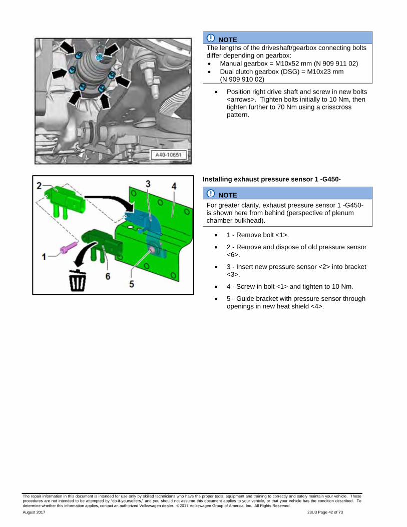
NOTE The lengths of the driveshaft/gearbox connecting bolts differ depending on gearbox: Manual gearbox = M10x52 mm (N 909 911 02) Dual clutch gearbox (DSG) = M10x23 mm
(N 909 910 02)
Position right drive shaft and screw in new bolts <arrows>. Tighten bolts initially to 10 Nm, then tighten further to 70 Nm using a crisscross pattern.
Installing exhaust pressure sensor 1 -G450-
NOTE
For greater clarity, exhaust pressure sensor 1 -G450- is shown here from behind (perspective of plenum chamber bulkhead).
1 - Remove bolt <1>.
2 - Remove and dispose of old pressure sensor <6>.
3 - Insert new pressure sensor <2> into bracket <3>.
4 - Screw in bolt <1> and tighten to 10 Nm.
5 - Guide bracket with pressure sensor through openings in new heat shield <4>.

The repair information in this document is intended for use only by skilled technicians who have the proper tools, equipment and training to correctly and safely maintain your vehicle. These procedures are not intended to be attempted by “do-it-yourselfers,” and you should not assume this document applies to your vehicle, or that your vehicle has the condition described. To determine whether this information applies, contact an authorized Volkswagen dealer. 2017 Volkswagen Group of America, Inc. All Rights Reserved.
August 2017 23U3 Page 43 of 73
NOTE
Take care to connect the hoses <6> (thin) and <1> (thick) correctly.
Guide exhaust pressure sensor 1 -G450- <3> into open ends of hoses as shown and secure thicker hose <1> with new clamp <2>.
Screw in bolt <4>, tighten to 2 Nm and connect connecter <5>.
Close fasteners on heat insulation mat <1> around exhaust pressure sensor 1 -G450-.
Wrap new heat insulation mat <2> around wiring and close fasteners.
The repair information in this document is intended for use only by skilled technicians who have the proper tools, equipment and training to correctly and safely maintain your vehicle. These procedures are not intended to be attempted by “do-it-yourselfers,” and you should not assume this document applies to your vehicle, or that your vehicle has the condition described. To determine whether this information applies, contact an authorized Volkswagen dealer. 2017 Volkswagen Group of America, Inc. All Rights Reserved.
August 2017 23U3 Page 44 of 73
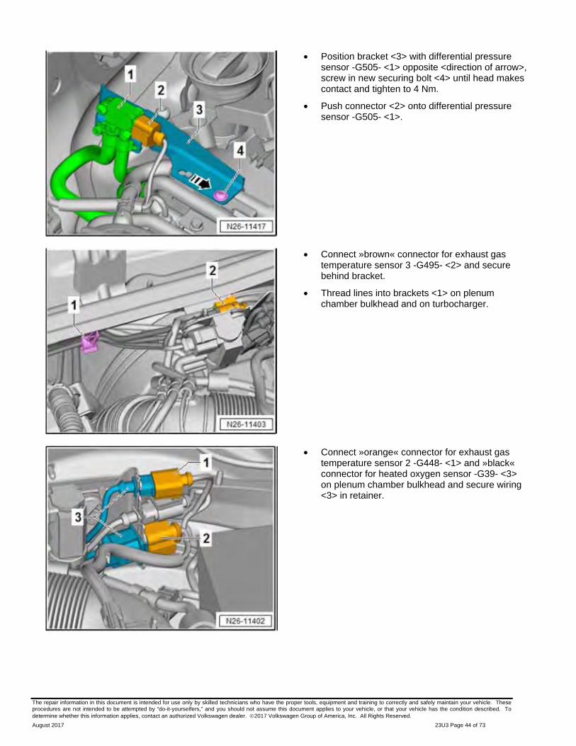
Position bracket <3> with differential pressure sensor -G505- <1> opposite <direction of arrow>, screw in new securing bolt <4> until head makes contact and tighten to 4 Nm.
Push connector <2> onto differential pressure sensor -G505- <1>.
Connect »brown« connector for exhaust gas temperature sensor 3 -G495- <2> and secure behind bracket.
Thread lines into brackets <1> on plenum chamber bulkhead and on turbocharger.
Connect »orange« connector for exhaust gas temperature sensor 2 -G448- <1> and »black« connector for heated oxygen sensor -G39- <3> on plenum chamber bulkhead and secure wiring <3> in retainer.
The repair information in this document is intended for use only by skilled technicians who have the proper tools, equipment and training to correctly and safely maintain your vehicle. These procedures are not intended to be attempted by “do-it-yourselfers,” and you should not assume this document applies to your vehicle, or that your vehicle has the condition described. To determine whether this information applies, contact an authorized Volkswagen dealer. 2017 Volkswagen Group of America, Inc. All Rights Reserved.
August 2017 23U3 Page 45 of 73
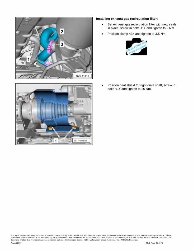
Installing exhaust gas recirculation filter:
Set exhaust gas recirculation filter with new seals in place, screw in bolts <1> and tighten to 9 Nm.
Position clamp <3> and tighten to 3.5 Nm.
Position heat shield for right drive shaft, screw in bolts <1> and tighten to 25 Nm.

The repair information in this document is intended for use only by skilled technicians who have the proper tools, equipment and training to correctly and safely maintain your vehicle. These procedures are not intended to be attempted by “do-it-yourselfers,” and you should not assume this document applies to your vehicle, or that your vehicle has the condition described. To determine whether this information applies, contact an authorized Volkswagen dealer. 2017 Volkswagen Group of America, Inc. All Rights Reserved.
August 2017 23U3 Page 46 of 73
Installing NOx storage catalytic converter with exhaust door control unit -J883-
Screw oxygen sensor after catalytic converter -G130- <2> into NOx storage catalytic converter <1> and tighten to 52 Nm.
NOTE
The clamps before and after the exhaust door control unit are narrower than the clamp connecting the particulate filter to the NOx storage catalytic converter. Ensure that they are correctly allocated.
Set new exhaust door control unit -J883- <5> with new seal <3> on NOx storage catalytic converter <1>. Note notches <arrows>.
Position clamp 1K0 253 725 B <4> and tighten to 7 Nm.
Place NOx storage catalytic converter together with exhaust door control unit -J883- with new seals in installation position. Note notches at rear connection.
Position all clamps <1> so that they will not collide with underbody.
NOTE
Install clamps on the exhaust pipe before installing pipe into vehicle. Do not attempt to stretch clamps around pipe once installed, or clamps may fail to seal properly.
Set clamp 1K0 253 725 B <2> in place and engage. Then tighten to 7 Nm.
Set clamp 1K0 253 725 <1> in place and engage. Then tighten to 7 Nm.
The repair information in this document is intended for use only by skilled technicians who have the proper tools, equipment and training to correctly and safely maintain your vehicle. These procedures are not intended to be attempted by “do-it-yourselfers,” and you should not assume this document applies to your vehicle, or that your vehicle has the condition described. To determine whether this information applies, contact an authorized Volkswagen dealer. 2017 Volkswagen Group of America, Inc. All Rights Reserved.
August 2017 23U3 Page 47 of 73
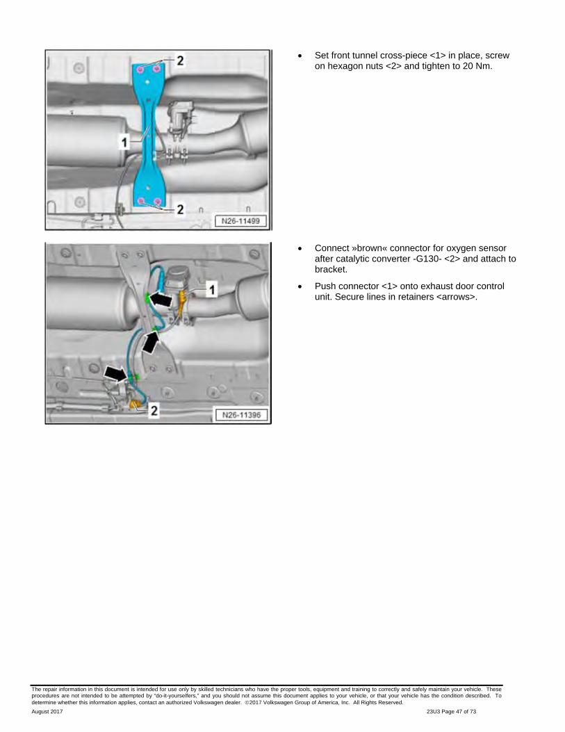
Set front tunnel cross-piece <1> in place, screw on hexagon nuts <2> and tighten to 20 Nm.
Connect »brown« connector for oxygen sensor after catalytic converter -G130- <2> and attach to bracket.
Push connector <1> onto exhaust door control unit. Secure lines in retainers <arrows>.
The repair information in this document is intended for use only by skilled technicians who have the proper tools, equipment and training to correctly and safely maintain your vehicle. These procedures are not intended to be attempted by “do-it-yourselfers,” and you should not assume this document applies to your vehicle, or that your vehicle has the condition described. To determine whether this information applies, contact an authorized Volkswagen dealer. 2017 Volkswagen Group of America, Inc. All Rights Reserved.
August 2017 23U3 Page 48 of 73
Routing electrical wiring on underbody:
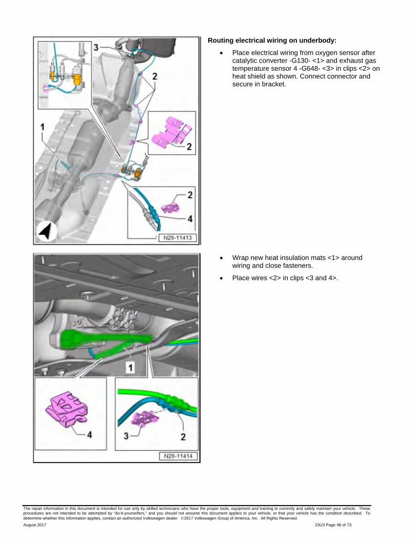
Place electrical wiring from oxygen sensor after catalytic converter -G130- <1> and exhaust gas temperature sensor 4 -G648- <3> in clips <2> on heat shield as shown. Connect connector and secure in bracket.
Wrap new heat insulation mats <1> around wiring and close fasteners.
Place wires <2> in clips <3 and 4>.
The repair information in this document is intended for use only by skilled technicians who have the proper tools, equipment and training to correctly and safely maintain your vehicle. These procedures are not intended to be attempted by “do-it-yourselfers,” and you should not assume this document applies to your vehicle, or that your vehicle has the condition described. To determine whether this information applies, contact an authorized Volkswagen dealer. 2017 Volkswagen Group of America, Inc. All Rights Reserved.
August 2017 23U3 Page 49 of 73
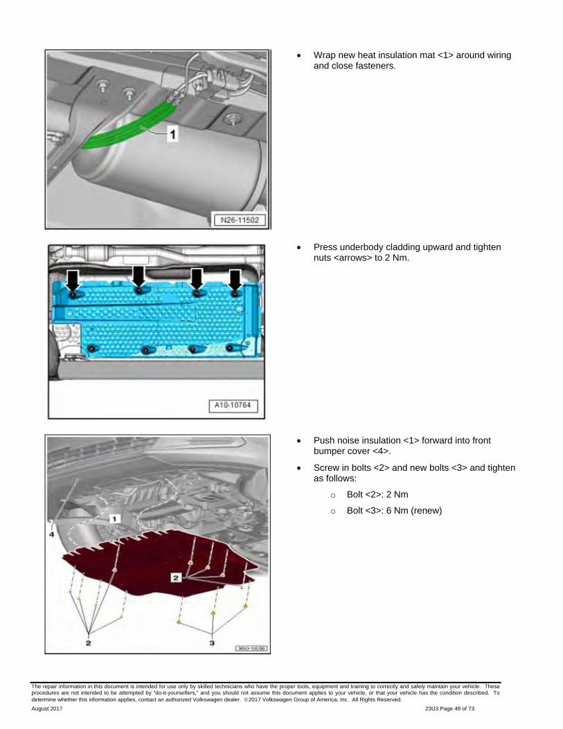
Wrap new heat insulation mat <1> around wiring and close fasteners.
Press underbody cladding upward and tighten nuts <arrows> to 2 Nm.
Push noise insulation <1> forward into front bumper cover <4>.
Screw in bolts <2> and new bolts <3> and tighten as follows:
o Bolt <2>: 2 Nm
o Bolt <3>: 6 Nm (renew)

The repair information in this document is intended for use only by skilled technicians who have the proper tools, equipment and training to correctly and safely maintain your vehicle. These procedures are not intended to be attempted by “do-it-yourselfers,” and you should not assume this document applies to your vehicle, or that your vehicle has the condition described. To determine whether this information applies, contact an authorized Volkswagen dealer. 2017 Volkswagen Group of America, Inc. All Rights Reserved.
August 2017 23U3 Page 50 of 73
NOTE
On one-piece DPF with NOx trap system (MY 2009 cars), the NOx trap must be separated from the DPF.
Separate NOx trap from DPF using -VAS6254- Chain Pipe Cutter (or equivalent).
Install the RED validation strap to the NOx catalytic converter <as shown> to confirm that the proper part is being returned for core.
The repair information in this document is intended for use only by skilled technicians who have the proper tools, equipment and training to correctly and safely maintain your vehicle. These procedures are not intended to be attempted by “do-it-yourselfers,” and you should not assume this document applies to your vehicle, or that your vehicle has the condition described. To determine whether this information applies, contact an authorized Volkswagen dealer. 2017 Volkswagen Group of America, Inc. All Rights Reserved.
August 2017 23U3 Page 51 of 73
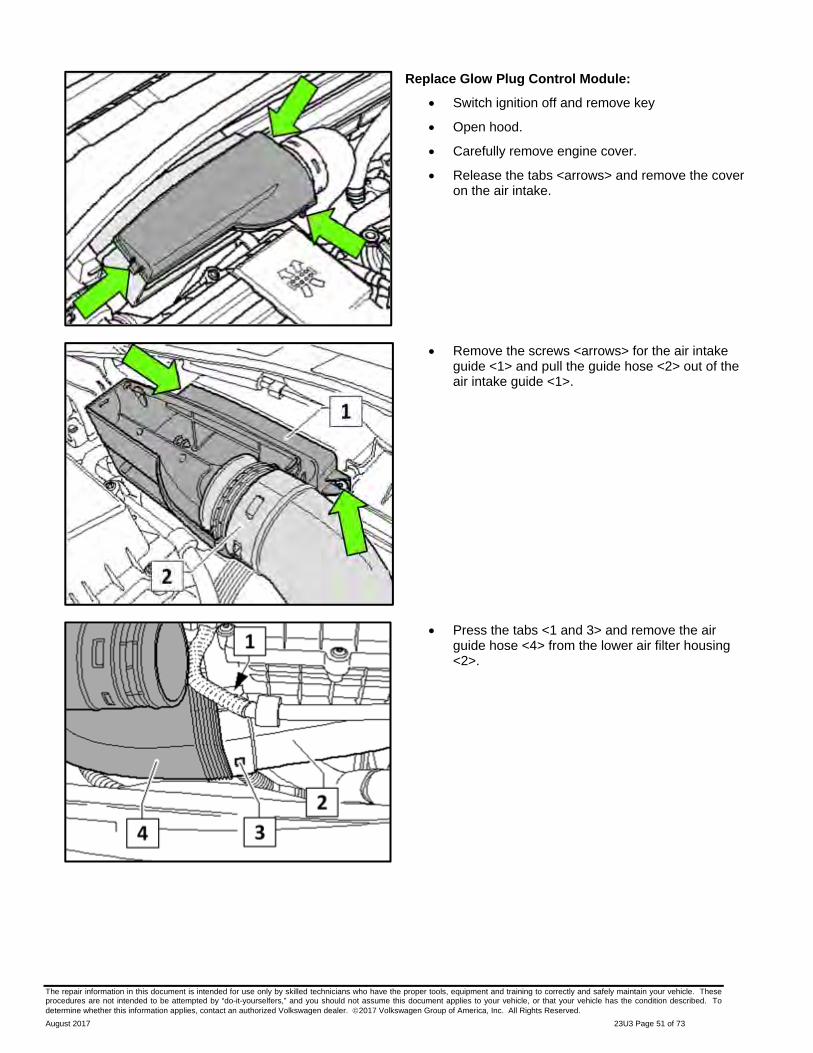
Replace Glow Plug Control Module:
Switch ignition off and remove key
Open hood.
Carefully remove engine cover.
Release the tabs <arrows> and remove the cover on the air intake.
Remove the screws <arrows> for the air intake guide <1> and pull the guide hose <2> out of the air intake guide <1>.
Press the tabs <1 and 3> and remove the air guide hose <4> from the lower air filter housing <2>.
The repair information in this document is intended for use only by skilled technicians who have the proper tools, equipment and training to correctly and safely maintain your vehicle. These procedures are not intended to be attempted by “do-it-yourselfers,” and you should not assume this document applies to your vehicle, or that your vehicle has the condition described. To determine whether this information applies, contact an authorized Volkswagen dealer. 2017 Volkswagen Group of America, Inc. All Rights Reserved.
August 2017 23U3 Page 52 of 73
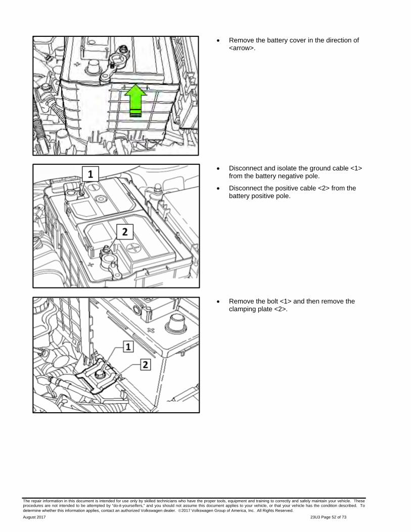
Remove the battery cover in the direction of <arrow>.
Disconnect and isolate the ground cable <1> from the battery negative pole.
Disconnect the positive cable <2> from the battery positive pole.
Remove the bolt <1> and then remove the clamping plate <2>.

The repair information in this document is intended for use only by skilled technicians who have the proper tools, equipment and training to correctly and safely maintain your vehicle. These procedures are not intended to be attempted by “do-it-yourselfers,” and you should not assume this document applies to your vehicle, or that your vehicle has the condition described. To determine whether this information applies, contact an authorized Volkswagen dealer. 2017 Volkswagen Group of America, Inc. All Rights Reserved.
August 2017 23U3 Page 53 of 73
Fold up the handles <arrows> and remove the battery.
To remove, slide the glow plug control module with bracket <1> outward from underneath the left engine compartment E-box in <direction of arrow>.
Inspect, and if required, replace the glow plug control module based upon the part number.
o If part number “03L 907 281 B” <arrow> is present, continue the work procedure and reinstall the glow plug control module.
o If part number “03L 907 281 B” <arrow> is not present, you are required to replace the glow plug control module with part number 03L 907 281 B.
If the glow plug control module requires replacement, disconnect electrical connector, remove screw with bracket and reinstall onto new glow plug control module with part number 03L 907 281 B.

The repair information in this document is intended for use only by skilled technicians who have the proper tools, equipment and training to correctly and safely maintain your vehicle. These procedures are not intended to be attempted by “do-it-yourselfers,” and you should not assume this document applies to your vehicle, or that your vehicle has the condition described. To determine whether this information applies, contact an authorized Volkswagen dealer. 2017 Volkswagen Group of America, Inc. All Rights Reserved.
August 2017 23U3 Page 54 of 73
To reinstall, slide glow plug control module <1> into position underneath left engine compartment E-box <in direction of arrow>.
Reinstall battery.
Reinstall the clamping plate <2> with bolt <1> and torque to 20Nm.
First, reconnect positive cable to positive terminal on battery and torque screw <1> to 6Nm.
Second, reconnect negative cable to negative terminal on battery and torque screw <2> to 6Nm.
Reinstall battery cover.

The repair information in this document is intended for use only by skilled technicians who have the proper tools, equipment and training to correctly and safely maintain your vehicle. These procedures are not intended to be attempted by “do-it-yourselfers,” and you should not assume this document applies to your vehicle, or that your vehicle has the condition described. To determine whether this information applies, contact an authorized Volkswagen dealer. 2017 Volkswagen Group of America, Inc. All Rights Reserved.
August 2017 23U3 Page 55 of 73
Reinstall the air filter housing.
Tighten the bolt <3> for the lower air filter housing.
Reinstall the air intake tube and close the clamp <4>.
Reconnect the Mass Airflow Sensor -G70- connector <1> and the vacuum line <2>.
Reinstall the air guide hose <4> onto the lower air filter housing <2>.
Reinstall the air intake guide <1> and air intake guide hose <2>, then tighten the screws <arrows>.

The repair information in this document is intended for use only by skilled technicians who have the proper tools, equipment and training to correctly and safely maintain your vehicle. These procedures are not intended to be attempted by “do-it-yourselfers,” and you should not assume this document applies to your vehicle, or that your vehicle has the condition described. To determine whether this information applies, contact an authorized Volkswagen dealer. 2017 Volkswagen Group of America, Inc. All Rights Reserved.
August 2017 23U3 Page 56 of 73
Reinstall the cover on the air intake and secure tabs <arrows>.
Reinstall engine cover.
Switch on ignition.
TIP
The ASR/ESP Control Lamp –K155– will light up continuously until the vehicle is driven 15 to 20km/h. This will activate the Steering Angle Sensor –G85–.
Connect Diagnostic Tester and clear faults.
Disconnect Diagnostic Tester.
Check and reset the clock.
Completely open/close all power windows and set pinch protection.
Perform function test of all electrical consumers.
Proceed to Section F
The repair information in this document is intended for use only by skilled technicians who have the proper tools, equipment and training to correctly and safely maintain your vehicle. These procedures are not intended to be attempted by “do-it-yourselfers,” and you should not assume this document applies to your vehicle, or that your vehicle has the condition described. To determine whether this information applies, contact an authorized Volkswagen dealer. 2017 Volkswagen Group of America, Inc. All Rights Reserved.
August 2017 23U3 Page 57 of 73
Section F – Software Update Procedure (All Criteria)
NOTE
Prior to launching the VAS Diagnostic Tester and starting an update, ensure the following conditions are met;
The ODIS software is completely up to date.
Refer to the “Alerts” section on ServiceNet home page for the current ODIS version.
The battery charger is connected to the vehicle battery and remains connected for the duration of the software update.
Battery voltage must remain above 12.5 volts for the duration of the software update. Failure to do so may cause the update to fail, which could result in damage to the control module. Control modules damaged by insufficient voltage will not be covered.
The screen saver and power saving settings are off.
Failure to do so may result in the tester entering power save mode during the software update, which could result in damage to the control module.
The VAS Diagnostic Tester is plugged in using the supplied power adapters.
Under no circumstances should the tester be used on battery power alone during the software
update. Failure to do so may result in the tester powering off during the update, which could result in damage to the control module.
If using the Bluetooth or WiFi transmitter head, it must be connected to the tester with a USB cable.
NOTE
Using Bluetooth for this action is PROHIBITED!
Damage caused to electronic components (e.g. ECM, TCM, etc.) during the SVM flash process is not covered.
Performing a software update using a Bluetooth connection increases the risk of losing
connection during the update, which could result in damage to the control module. It also greatly increases the time required to perform the update. Requests for additional time or parts will be denied if the GFF log shows the update was performed using Bluetooth.
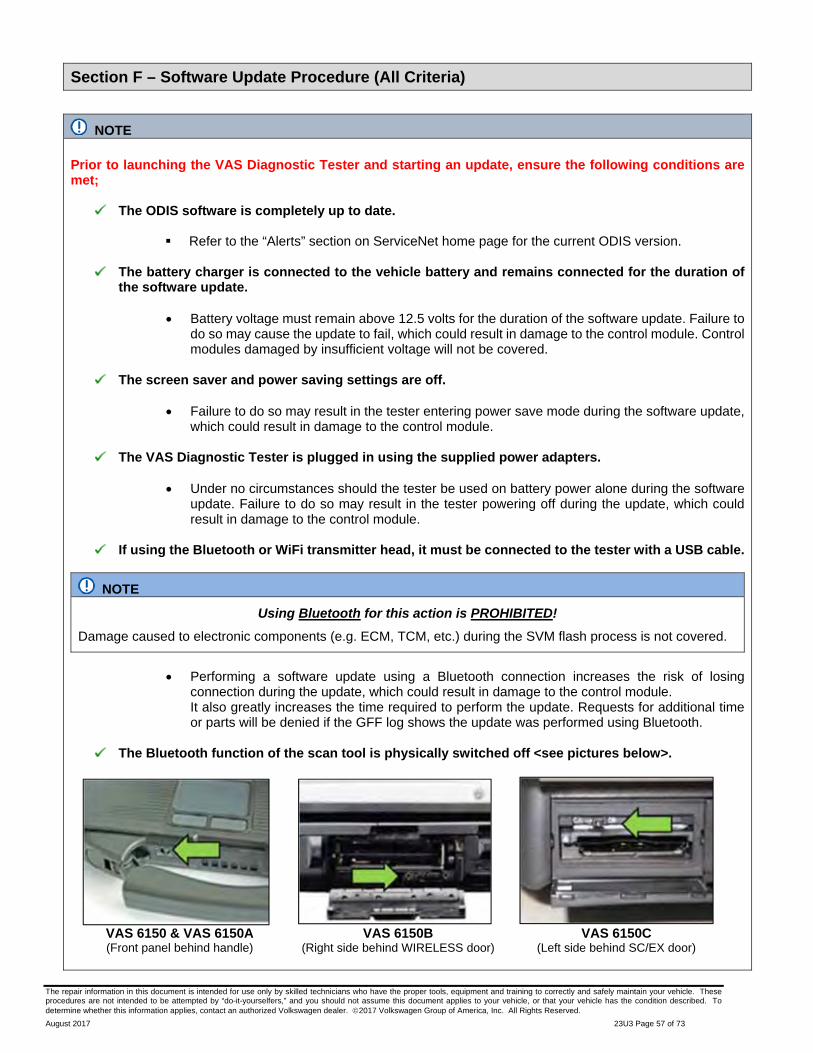
The Bluetooth function of the scan tool is physically switched off <see pictures below>.
VAS 6150 & VAS 6150A (Front panel behind handle)
VAS 6150B (Right side behind WIRELESS door)
VAS 6150C (Left side behind SC/EX door)

The repair information in this document is intended for use only by skilled technicians who have the proper tools, equipment and training to correctly and safely maintain your vehicle. These procedures are not intended to be attempted by “do-it-yourselfers,” and you should not assume this document applies to your vehicle, or that your vehicle has the condition described. To determine whether this information applies, contact an authorized Volkswagen dealer. 2017 Volkswagen Group of America, Inc. All Rights Reserved.
August 2017 23U3 Page 58 of 73
WARNING
Radiator Fan(s) may cycle ON high speed during the Update Process! There is a serious risk that personal injury may result if contact is made with spinning fan blades. Keep hands and all objects away from Radiator Fan(s) during Update Process!
TIP
To Update-Programming using SVM, review and follow instructions in Technical Bulletin 2014603: Software Version Management (SVM) Operating Instructions.
The SVM Process must be completed in its entirety so the database receives the update confirmation response. A warranty claim may not be reimbursed if there is no confirmation response to support the claim.
Things to check before starting Software Version Management (SVM):
Check and confirm that you have a LAN connection <arrow>.
Within the Connection Tab, verify that the Connection type(s) display “Internet” <as shown>.
Start a connections test <arrow> and verify that all connections pass.

The repair information in this document is intended for use only by skilled technicians who have the proper tools, equipment and training to correctly and safely maintain your vehicle. These procedures are not intended to be attempted by “do-it-yourselfers,” and you should not assume this document applies to your vehicle, or that your vehicle has the condition described. To determine whether this information applies, contact an authorized Volkswagen dealer. 2017 Volkswagen Group of America, Inc. All Rights Reserved.
August 2017 23U3 Page 59 of 73
Open the hood.
Open the battery cover.
Attach the GRX3000VAS Tester/Charger (or equivalent) to the vehicle battery.
Switch the ignition on.
Apply the parking brake.
Switch the headlights off.
Connect the VAS6150X Diagnostic Tester (or equivalent) to the vehicle.
Start the ODIS program.
NOTE
STOP! All TDI flashes MUST be completed during a single, standalone ODIS Diagnostic Session. You MUST fully complete this campaign and send all GFF Paperless logs before beginning any other campaigns or operations. You MUST also conclude any other campaigns or operations that have been started and end the corresponding diagnostic session and send all GFF Paperless logs before beginning this operation. Failure to independently separate the ODIS diagnostic session for this campaign will cause problems updating the FAZIT server in Germany and will delay if not negate the payment of the emissions modification.
IMPORTANT!
If there are any ODIS “Hot-Fix” patches installed, they MUST be removed from the scan tool before beginning this operation. ODIS “Hot-Fix” patches may affect the flash process.
At this time, refer to the “Alerts” section of ServiceNet <arrow> to verify that the most recent version of ODIS Software is loaded to the VAS6150X Diagnostic Tester (or equivalent). Failure to flash the vehicle using the most recent version of ODIS Diagnostic Software will cause faults in certain features of the flash operation.
Failure to validate the ODIS Diagnostic version before flashing the vehicle may result in flash failure, and may delay if not negate the payment of the emissions modification.

The repair information in this document is intended for use only by skilled technicians who have the proper tools, equipment and training to correctly and safely maintain your vehicle. These procedures are not intended to be attempted by “do-it-yourselfers,” and you should not assume this document applies to your vehicle, or that your vehicle has the condition described. To determine whether this information applies, contact an authorized Volkswagen dealer. 2017 Volkswagen Group of America, Inc. All Rights Reserved.
August 2017 23U3 Page 60 of 73
Confirm that scan tool is communicating with the diagnostic head by USB <Green Arrow>.
o If the Bluetooth symbol is shown <Red Arrow> then disconnect the diagnostic head from the vehicle and reconnect the USB cable to the diagnostic head and then reattach to the vehicle.
Upon ODIS startup, verify the “Diagnosis” operating mode is selected <as shown>.
NOTE
For the duration of the flash, the following is required to keep the BUS system active during the flash process:
Driver side door open
Doors unlocked
Hazzard flashers in the “On” position
NOTE
KESSY Vehicles!
If loss of communication between the reader coil and the key occurs during the flash, it may damage a control module.
If equipped with a removable reader coil cap, it is REQUIRED to remove the reader coil cap and insert the key into the reader coil, or secure the key in close proximity to the reader coil throughout the flash process.
If the reader coil cap is not removable, it is REQUIRED to secure the key to the steering column in close proximity to the reader coil using a residue-free adhesive or tape, an elastic cloth or stretch bandage, or other improvised retaining device.

The repair information in this document is intended for use only by skilled technicians who have the proper tools, equipment and training to correctly and safely maintain your vehicle. These procedures are not intended to be attempted by “do-it-yourselfers,” and you should not assume this document applies to your vehicle, or that your vehicle has the condition described. To determine whether this information applies, contact an authorized Volkswagen dealer. 2017 Volkswagen Group of America, Inc. All Rights Reserved.
August 2017 23U3 Page 61 of 73
Once the GFF scan is complete, select “Special functions”.
Select the test plan “Adapt software, diesel, exhaust EA189 action 23XX” <as shown>.
Select “Perform test” <arrow>.
NOTE
RISK of Scan Tool Damage!
Do not leave the scan tool on the windshield during the flash process, as it is possible that the windshield wipers may cycle.
NOTE
RISK of Improper Repair!
DO NOT SELECT the normal test plan for “Adapting Software”.
ONLY SELECT the test plan “Adapt software, diesel, exhaust EA189 action 23XX” to perform this repair.
Select “Complete/Continue” <arrow> after the control module adaptation, action 23XX note appears.
NOTE
Using Bluetooth for this action is PROHIBITED!
Damage caused to electronic components (e.g. ECM, TCM, etc.) during the SVM flash process is not covered.
Enter the corrective action code (SVM code) as listed below.
SVM code
3DED
Select “Accept” <arrow>.

The repair information in this document is intended for use only by skilled technicians who have the proper tools, equipment and training to correctly and safely maintain your vehicle. These procedures are not intended to be attempted by “do-it-yourselfers,” and you should not assume this document applies to your vehicle, or that your vehicle has the condition described. To determine whether this information applies, contact an authorized Volkswagen dealer. 2017 Volkswagen Group of America, Inc. All Rights Reserved.
August 2017 23U3 Page 62 of 73
After selecting “Accept”, a self-check routine that tests the integrity of the Heated Oxygen Sensor -G39- occurs in the background. This self-check is automated and requires no input to initiate.
You may receive the message “Replace the heated oxygen sensor -G39- (before catalytic converter), Refer to the Repair Manual, Repair Group 23” <arrow 1>:
o If Campaign 24CV has NOT been completed, STOP and perform that action at this time. When complete, return to the beginning of Section F to restart the flash process.
o If Campaign 24CV has been completed, select “Complete/Continue” <arrow 2> to bypass this operation and proceed to the next step.
Select “Complete/Continue” <arrow> to begin the software update process.
Observe flash process and follow any on-screen prompts to complete the test plan.

The repair information in this document is intended for use only by skilled technicians who have the proper tools, equipment and training to correctly and safely maintain your vehicle. These procedures are not intended to be attempted by “do-it-yourselfers,” and you should not assume this document applies to your vehicle, or that your vehicle has the condition described. To determine whether this information applies, contact an authorized Volkswagen dealer. 2017 Volkswagen Group of America, Inc. All Rights Reserved.
August 2017 23U3 Page 63 of 73
Follow all prompts as requested per the test plan.
o Switch the ignition ON or OFF when requested to do so.
o Select “Complete/Continue” <arrow> when prompted to do so.
NOTE
It is IMPERATIVE that ALL of the ignition cycle on/off delay requests are fulfilled in their entirety during this flash process <arrow 1>.
Failing to wait for the ignition on/off timing cycle to complete (progress bar and countdown timer <arrow 2>) before cycling the ignition on/off MAY damage a control module.
Damage to control modules as a result of failing to wait the specified time displayed by the progress bar and countdown timer <arrow 2> are NOT covered under this action.
The green check mark indicates the test plan was successfully carried out.
NOTE
In the event of a Flash Malfunction!
In the event of a flash error or malfunction, STOP. DO NOT exit the ODIS session, disconnect the scan tool, attempt the flash again, or continue further in the test plan.
Create a VTA ticket and allow the VW Technicians Helpline to provide direction with flash failures.

The repair information in this document is intended for use only by skilled technicians who have the proper tools, equipment and training to correctly and safely maintain your vehicle. These procedures are not intended to be attempted by “do-it-yourselfers,” and you should not assume this document applies to your vehicle, or that your vehicle has the condition described. To determine whether this information applies, contact an authorized Volkswagen dealer. 2017 Volkswagen Group of America, Inc. All Rights Reserved.
August 2017 23U3 Page 64 of 73
After the software update is completed and before sending the GFF Log Online:
o Select the “Control Module” tab.
o Scroll down and right click on Address Word 0001/ Engine Control Module.
o Select “Identify Control Module” <arrow>.
At the end of the diagnostic session, Select “Send” <arrow> and follow the prompt for sending the log on-line.
NOTE
RISK of Non-payment!
Diagnosis logs must be sent on-line after the flash process to be considered for reimbursement.
Verify that no other Campaigns or operations are performed during this ODIS diagnostic session before sending the log, and verify that the Engine Control Module has been re-identified.
TIP
Technicians may find it helpful to also store the log on a USB stick for back-up.
TIP
When exiting GFF, it is important to select “No” <arrow>.
TIP
It is possible after the flash that the TPMS light may be illuminated. Follow test plan “03 – Tire pressure monitoring display” <as shown>.
If TPMS light illuminates, follow test plan “03 – Tire pressure monitoring display” by selecting “Perform test” <arrow>.
End the diagnostic session fully, exit the scan tool, and disconnect the VAS tester.
The repair information in this document is intended for use only by skilled technicians who have the proper tools, equipment and training to correctly and safely maintain your vehicle. These procedures are not intended to be attempted by “do-it-yourselfers,” and you should not assume this document applies to your vehicle, or that your vehicle has the condition described. To determine whether this information applies, contact an authorized Volkswagen dealer. 2017 Volkswagen Group of America, Inc. All Rights Reserved.
August 2017 23U3 Page 65 of 73
Switch off and disconnect the battery charger.
Reinstall the battery cover.
Release the parking brake.
Perform test drive.
NOTE
DO NOT drive vehicle without having both new software and new hardware as doing so will damage to the newly installed components.
Proceed to Section G

The repair information in this document is intended for use only by skilled technicians who have the proper tools, equipment and training to correctly and safely maintain your vehicle. These procedures are not intended to be attempted by “do-it-yourselfers,” and you should not assume this document applies to your vehicle, or that your vehicle has the condition described. To determine whether this information applies, contact an authorized Volkswagen dealer. 2017 Volkswagen Group of America, Inc. All Rights Reserved.
August 2017 23U3 Page 66 of 73
Section G – Supplemental Vehicle Emissions Control Information Label
Install Supplemental Vehicle Emissions Control Information Label
TIP
The surface where the label is to be installed must be clean, dry, and free from oil residue prior to installing the label.
Label must NOT cover any existing label(s).
Label must be installed in locations shown.
Photo documentation of label installed is required.
Open the hood.
Clean the surface where the label is to be installed <circled areas are examples>.
Install the supplemental Vehicle Emissions Control Information label, 03L 010 005 G, according to the following guidelines:
o Painted surface
o In a readily visible position on the underside of the hood
o In as close proximity to the original VECI label as possible
o In as close proximity (for picture purposes) of the Campaign Completion Label
NOTE
DO NOT Cover existing VECI label!
New Vehicle Emissions Control Information (VECI) label MUST NOT be placed over original VECI label.
Proceed to Section H

The repair information in this document is intended for use only by skilled technicians who have the proper tools, equipment and training to correctly and safely maintain your vehicle. These procedures are not intended to be attempted by “do-it-yourselfers,” and you should not assume this document applies to your vehicle, or that your vehicle has the condition described. To determine whether this information applies, contact an authorized Volkswagen dealer. 2017 Volkswagen Group of America, Inc. All Rights Reserved.
August 2017 23U3 Page 67 of 73

The repair information in this document is intended for use only by skilled technicians who have the proper tools, equipment and training to correctly and safely maintain your vehicle. These procedures are not intended to be attempted by “do-it-yourselfers,” and you should not assume this document applies to your vehicle, or that your vehicle has the condition described. To determine whether this information applies, contact an authorized Volkswagen dealer. 2017 Volkswagen Group of America, Inc. All Rights Reserved.
August 2017 23U3 Page 68 of 73
Section H – Campaign Completion Label
Install Campaign Completion Label
TIP
The surface where the label is to be installed must be clean, dry, and free from oil residue prior to installing the label.
Label must NOT cover any existing label(s).
Photo documentation of label installed is required.
Clean the surface next to the Vehicle Emission
Control Information Label where the TDI Emissions Modification – Proof of Completion Label is to be installed.
Fill out and install the TDI Emissions Modification – Proof of Completion Label, part number:
o MY 2009 vehicles: CAMP TDI 2016_1A
o MY 2010-2014 vehicles: CAMP TDI 2016_1B
NOTE
Place the label next to the Vehicle Emission Control Information Label.
Apply clear overlay (provided)
Close the hood.
Proceed to Section I (California only).
Proceed to Section J (All without California).

The repair information in this document is intended for use only by skilled technicians who have the proper tools, equipment and training to correctly and safely maintain your vehicle. These procedures are not intended to be attempted by “do-it-yourselfers,” and you should not assume this document applies to your vehicle, or that your vehicle has the condition described. To determine whether this information applies, contact an authorized Volkswagen dealer. 2017 Volkswagen Group of America, Inc. All Rights Reserved.
August 2017 23U3 Page 69 of 73
Section I – California Only Requirements
CALIFORNIA ONLY Requirements for Emissions Campaigns Having Customer Notification
The California Air Resources Board and the Department of Motor Vehicles (DMV) require emissions-related campaigns to be completed prior to vehicle registration renewal. When campaign work is done you must provide the owner with a signed “Vehicle Emission Recall – Proof of Correction” certificate (RC EMIS_CAL VW). Certificates can be ordered at no cost online via the Compliance Label Ordering portal at www.vwhub.com.
TIP Ensure owners are aware of the importance of retaining the completed certificate for their records. It should be mailed to the California DMV only upon request.
Proceed to Section J
Section J – Service Modification Documentation Requirements
Job Roles Summary:
Service Consultant – Initiates validation tool.
Service Technician – Completes service modification requirements.
Manager – Validates the modification was properly completed.
Dealer Representative/Cashier – Prints receipt, fuel economy label and delivers to customer.
Warranty Administrator – Enters claim into the SAGA system.
TIP To access the interactive forms go to the TDI SettlementProgram microsite on vwhub.com. Then Select the “TDI IN-FORM” Button from the lower left side of the microsite navigation.
Enter the “TDI IN-FORM” tool <arrow>.

The repair information in this document is intended for use only by skilled technicians who have the proper tools, equipment and training to correctly and safely maintain your vehicle. These procedures are not intended to be attempted by “do-it-yourselfers,” and you should not assume this document applies to your vehicle, or that your vehicle has the condition described. To determine whether this information applies, contact an authorized Volkswagen dealer. 2017 Volkswagen Group of America, Inc. All Rights Reserved.
August 2017 23U3 Page 70 of 73
Enter the VIN for the vehicle that requires documentation.
TIPThe VIN can be manually typed in or using an iPad or iPhone running i0S 9+, the camera can be used to scan the VIN Barcode. Please note ambient lighting, camera quality, etc. may impact the effectiveness of the VIN scanning feature.
TIP After the VIN has been entered, the system will automatically validate that it is a TDI VIN. This will be indicated by a green check mark that will appear next to the VIN.
Validate the VIN is correct for the vehicle, then click the “Submit” button <arrow>.

The repair information in this document is intended for use only by skilled technicians who have the proper tools, equipment and training to correctly and safely maintain your vehicle. These procedures are not intended to be attempted by “do-it-yourselfers,” and you should not assume this document applies to your vehicle, or that your vehicle has the condition described. To determine whether this information applies, contact an authorized Volkswagen dealer. 2017 Volkswagen Group of America, Inc. All Rights Reserved.
August 2017 23U3 Page 71 of 73
Select “Service Modification Documentation Form” <arrow>.
Follow the on-screen prompts completely.
NOTE
RISK of Non-payment!
Not using the IN-FORM tool to document and validate the modification will stop the processing of payment for your dealership even if the modification has been completed.
TIPUpon completion of the Service Modification Documentation Form, the Manager must validate the repair in the IN-FORM tool.
ALL WORK IS COMPLETE for this Repair.
NOTE
At this time, refer to ELSA and address any additional open campaigns/recalls. If the 24CV Campaign has not yet been completed, refer to that action at this time. It is required to complete the 24CV Campaign PRIOR to this action in order to complete the TDI IN-FORM Tool requirements.

The repair information in this document is intended for use only by skilled technicians who have the proper tools, equipment and training to correctly and safely maintain your vehicle. These procedures are not intended to be attempted by “do-it-yourselfers,” and you should not assume this document applies to your vehicle, or that your vehicle has the condition described. To determine whether this information applies, contact an authorized Volkswagen dealer. 2017 Volkswagen Group of America, Inc. All Rights Reserved.
August 2017 23U3 Page 72 of 73
Appendix A – Parts Kits Identification and Details
Criteria 01 and 02 - 2.0L Base Kit 1 - 1K0 298 101 A (All Vehicles)
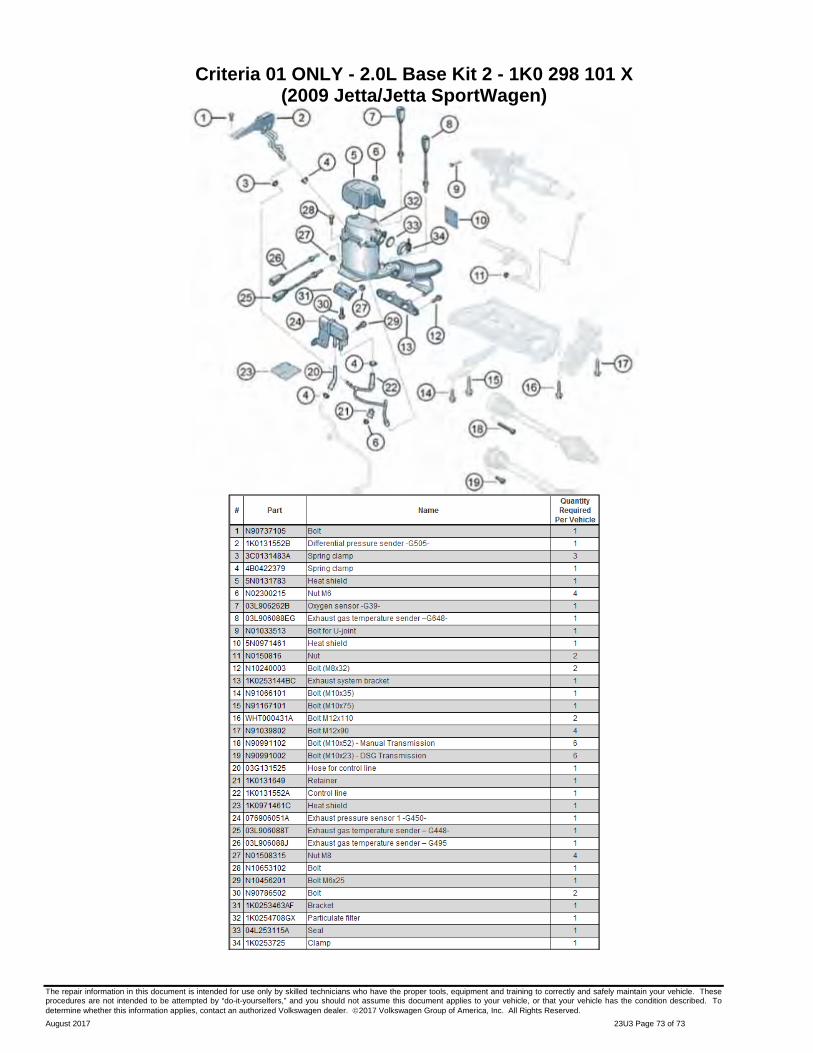
The repair information in this document is intended for use only by skilled technicians who have the proper tools, equipment and training to correctly and safely maintain your vehicle. These procedures are not intended to be attempted by “do-it-yourselfers,” and you should not assume this document applies to your vehicle, or that your vehicle has the condition described. To determine whether this information applies, contact an authorized Volkswagen dealer. 2017 Volkswagen Group of America, Inc. All Rights Reserved.
August 2017 23U3 Page 73 of 73
Criteria 01 ONLY - 2.0L Base Kit 2 - 1K0 298 101 X (2009 Jetta/Jetta SportWagen)