Emission Compliance, Automotive Regulations and Science ... · PDF...
58
Emission Compliance, Automotive Regulations and Science Division California Air Resources Board November 2, 2017 El Monte, CA
Transcript of Emission Compliance, Automotive Regulations and Science ... · PDF...
Emission Compliance, Automotive Regulations and Science Division
California Air Resources BoardNovember 2, 2017El Monte, CA
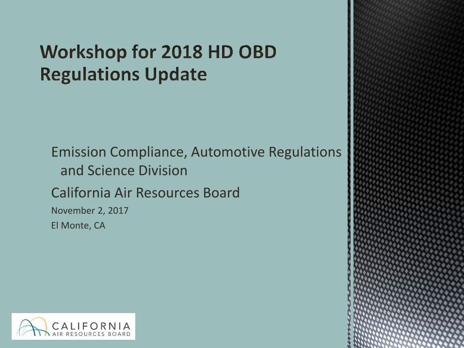
Projected Schedule (subject to change) Public Workshop – El Monte, CA Date: Thursday, November 2, 2017: 9am-3pm (today)
Finalization of HD OBD Regulatory Package Projected date: Late spring timeframe
45-Day Notice Package Projected publication date: Late summer/early fall 2018 Includes notice, staff report, and proposed regulatory language
Board Hearing Projected date: Late fall 2018
2
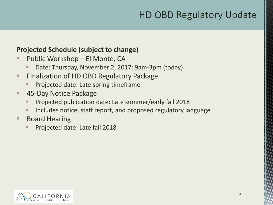
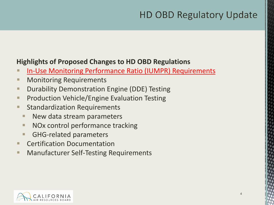
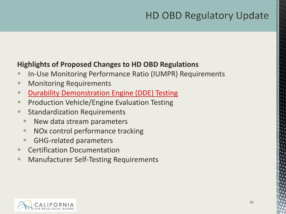
Highlights of Proposed Changes to HD OBD Regulations In-Use Monitoring Performance Ratio (IUMPR) Requirements Monitoring Requirements Durability Demonstration Engine (DDE) Testing Production Vehicle/Engine Evaluation Testing Standardization Requirements New data stream parameters NOx control performance tracking GHG-related parameters Certification Documentation Manufacturer Self-Testing Requirements
3
Highlights of Proposed Changes to HD OBD Regulations In-Use Monitoring Performance Ratio (IUMPR) Requirements Monitoring Requirements Durability Demonstration Engine (DDE) Testing Production Vehicle/Engine Evaluation Testing Standardization Requirements New data stream parameters NOx control performance tracking GHG-related parameters Certification Documentation Manufacturer Self-Testing Requirements
4
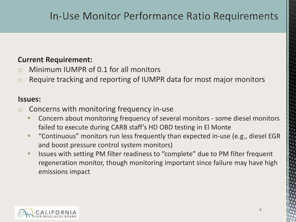
Current Requirement:o Minimum IUMPR of 0.1 for all monitors o Require tracking and reporting of IUMPR data for most major monitors
Issues:o Concerns with monitoring frequency in-use Concern about monitoring frequency of several monitors - some diesel monitors
failed to execute during CARB staff’s HD OBD testing in El Monte “Continuous” monitors run less frequently than expected in-use (e.g., diesel EGR
and boost pressure control system monitors) Issues with setting PM filter readiness to “complete” due to PM filter frequent
regeneration monitor, though monitoring important since failure may have high emissions impact
5
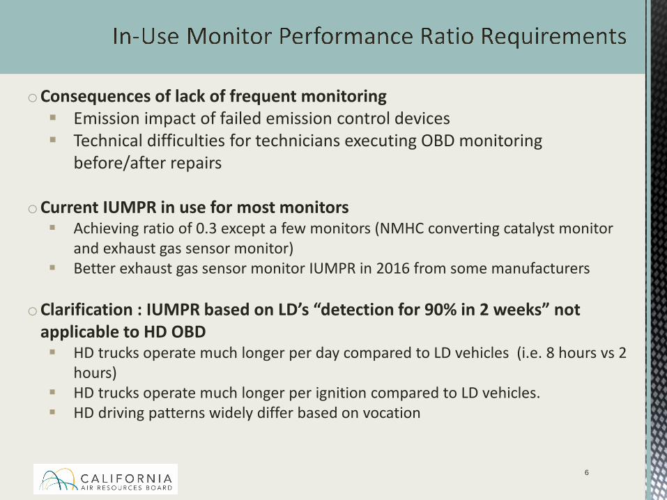
oConsequences of lack of frequent monitoring Emission impact of failed emission control devices Technical difficulties for technicians executing OBD monitoring
before/after repairs
oCurrent IUMPR in use for most monitors Achieving ratio of 0.3 except a few monitors (NMHC converting catalyst monitor
and exhaust gas sensor monitor) Better exhaust gas sensor monitor IUMPR in 2016 from some manufacturers
oClarification : IUMPR based on LD’s “detection for 90% in 2 weeks” not applicable to HD OBD HD trucks operate much longer per day compared to LD vehicles (i.e. 8 hours vs 2
hours) HD trucks operate much longer per ignition compared to LD vehicles. HD driving patterns widely differ based on vocation
6
7
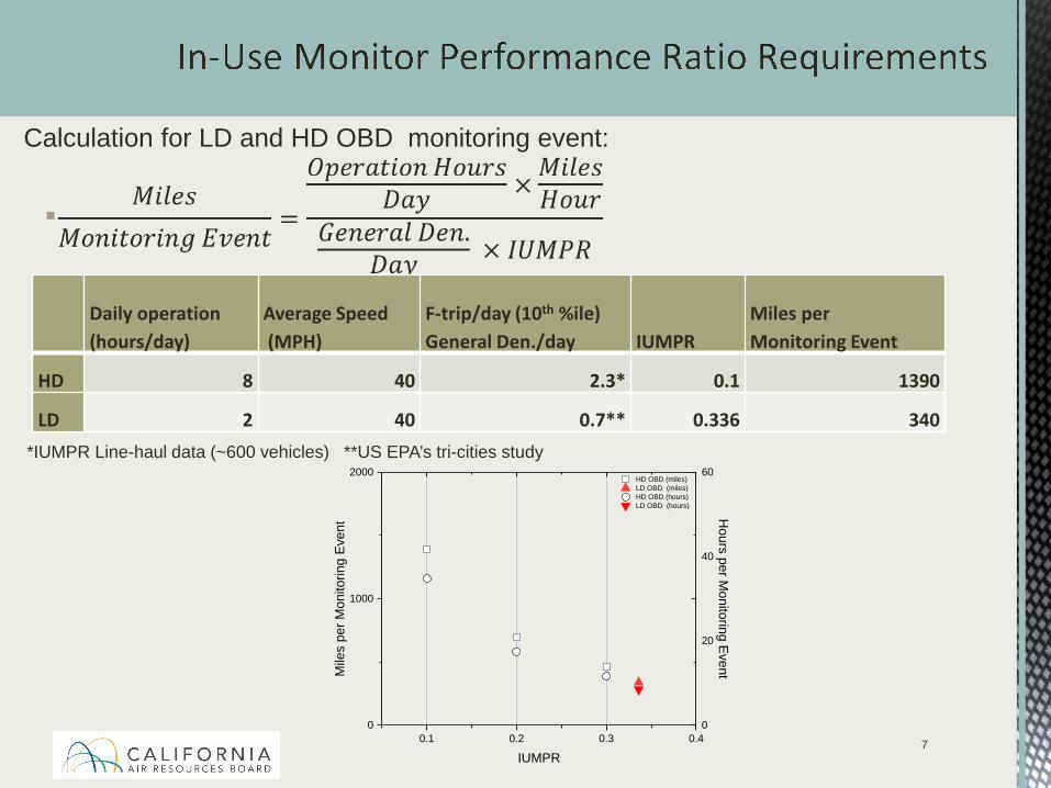
Calculation for LD and HD OBD monitoring event:
Daily operation (hours/day)
Average Speed(MPH)
F-trip/day (10th %ile)General Den./day IUMPR
Miles perMonitoring Event
HD 8 40 2.3* 0.1 1390
LD 2 40 0.7** 0.336 340*IUMPR Line-haul data (~600 vehicles) **US EPA’s tri-cities study
0.1 0.2 0.3 0.40
1000
2000 HD OBD (miles) LD OBD (miles) HD OBD (hours) LD OBD (hours)
Mile
s pe
r Mon
itorin
g Ev
ent
IUMPR
0
20
40
60
Hours per M
onitoring Event
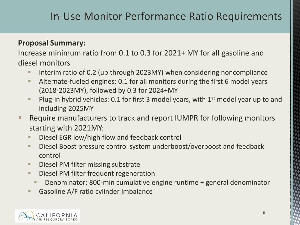
Proposal Summary: Increase minimum ratio from 0.1 to 0.3 for 2021+ MY for all gasoline and diesel monitors Interim ratio of 0.2 (up through 2023MY) when considering noncompliance Alternate-fueled engines: 0.1 for all monitors during the first 6 model years
(2018-2023MY), followed by 0.3 for 2024+MY Plug-in hybrid vehicles: 0.1 for first 3 model years, with 1st model year up to and
including 2025MY Require manufacturers to track and report IUMPR for following monitors
starting with 2021MY: Diesel EGR low/high flow and feedback control Diesel Boost pressure control system underboost/overboost and feedback
control Diesel PM filter missing substrate Diesel PM filter frequent regeneration Denominator: 800-min cumulative engine runtime + general denominator Gasoline A/F ratio cylinder imbalance
8
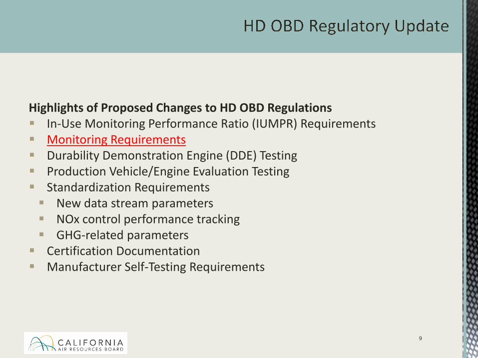
Highlights of Proposed Changes to HD OBD Regulations In-Use Monitoring Performance Ratio (IUMPR) Requirements Monitoring Requirements Durability Demonstration Engine (DDE) Testing Production Vehicle/Engine Evaluation Testing Standardization Requirements New data stream parameters NOx control performance tracking GHG-related parameters Certification Documentation Manufacturer Self-Testing Requirements
9
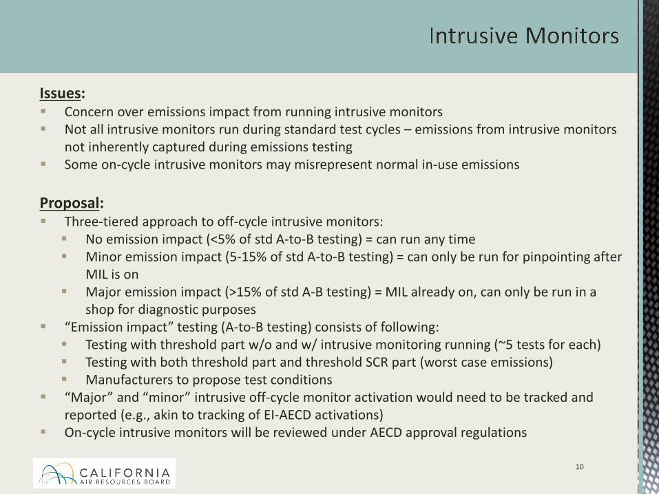
Issues: Concern over emissions impact from running intrusive monitors Not all intrusive monitors run during standard test cycles – emissions from intrusive monitors
not inherently captured during emissions testing Some on-cycle intrusive monitors may misrepresent normal in-use emissions
Proposal: Three-tiered approach to off-cycle intrusive monitors: No emission impact (<5% of std A-to-B testing) = can run any time Minor emission impact (5-15% of std A-to-B testing) = can only be run for pinpointing after
MIL is on Major emission impact (>15% of std A-B testing) = MIL already on, can only be run in a
shop for diagnostic purposes “Emission impact” testing (A-to-B testing) consists of following: Testing with threshold part w/o and w/ intrusive monitoring running (~5 tests for each) Testing with both threshold part and threshold SCR part (worst case emissions) Manufacturers to propose test conditions
“Major” and “minor” intrusive off-cycle monitor activation would need to be tracked and reported (e.g., akin to tracking of EI-AECD activations)
On-cycle intrusive monitors will be reviewed under AECD approval regulations
10
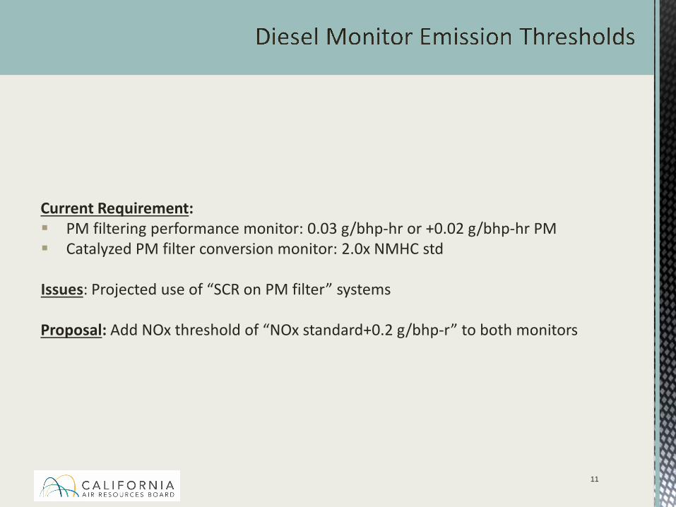
Current Requirement: PM filtering performance monitor: 0.03 g/bhp-hr or +0.02 g/bhp-hr PM Catalyzed PM filter conversion monitor: 2.0x NMHC std
Issues: Projected use of “SCR on PM filter” systems
Proposal: Add NOx threshold of “NOx standard+0.2 g/bhp-r” to both monitors
11
Current Requirement: Monitor NMHC catalysts and catalyzed PM filters for feedgas generation performance Test-Out Criteria – not required to monitor if all faults do not cause
emissions to (1) increase by >15% of standards AND (2) exceed standards
Issues: Lack of feasible monitoring strategies Question about failure conditions that result in worst case emissions
Proposal: Increase test-out criterion (1) from >15% to >30% of standards Only consider NOx emissions/standards for (1) and (2) Test conditions for test-out – Pd-only catalyst Monitoring and test-out testing determined using “system” monitor of
NMHC catalyst AND catalyzed PM filter
12
Current Requirement: Monitor for low reductant level and improper/wrong reductant
Issues: These conditions could be actual malfunctions of component/system on the vehicle or the result of driver action E.g., repair a cracked tank versus driver has to refill tank with correct reductant to
repair detected fault
Proposal : Allow manufacturers to be exempt from OBD monitoring requirements for low reductant level and wrong reductant if vehicle has an approved inducement strategy All inputs to inducement (e.g., reductant level sensing system, reductant quality
sensor) required to be monitored under comprehensive component monitoring requirements
13
Current Requirement: Monitor the CV system for disconnections or require robust connectionsIssues: Targets connections but not overall system integrity Objectivity in reviewing unmonitored system can be difficult and resource
intensive Proposal: Adopting similar language adopted for OBD II regulation in 2015 Monitor “breaks” or disconnections of CV system beginning in 2025 MY with full
phase-in in 2027MY Monitor for breaks of minimum cross sectional area of external lines and hoses
that transport crankcase vapors. Compliance not based on design criteria Some manufacturers have added sensors/algorithms to their systems to detect
disconnected lines. Such approaches may be capable of break detection. Exceptions to break/disconnection monitoring: Results in engine stall, rapid engine oil loss or other over indication for
immediate repair All internal CV system (e.g., internal machined passages, no tubing or hoses) Break occurs downstream of crankcase vapor delivery to air intake
system/filter14
Current Requirement: Monitor component that “can affect emission during any reasonable in-use driving condition.”
Issues: Though AECDs by definition are involved with the “activating, modulating, delaying,
or deactivating the operation of any part of the emission control system,” unclear if all manufacturers are currently monitoring all components used to activate AECDs.
Given the importance of inducement strategies for emissions control, need to ensure that inducement strategies are operating as expected and that any fault of a component that is involved in activating the inducement strategy is repaired in a timely manner. However, not all manufacturers are currently monitoring all components involved with inducement strategies.
Proposal: Include specific language requiring monitoring of all input components and output
components that are used as part of an AECD. No start date added since this is considered a clarification.
Include specific language requiring monitoring of all input components that are used as part of inducement strategy starting with the 2021 model year.
15
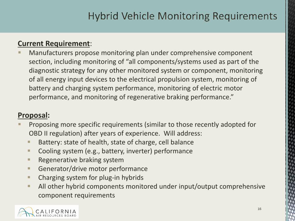
Current Requirement: Manufacturers propose monitoring plan under comprehensive component
section, including monitoring of “all components/systems used as part of the diagnostic strategy for any other monitored system or component, monitoring of all energy input devices to the electrical propulsion system, monitoring of battery and charging system performance, monitoring of electric motor performance, and monitoring of regenerative braking performance.”
Proposal: Proposing more specific requirements (similar to those recently adopted for
OBD II regulation) after years of experience. Will address: Battery: state of health, state of charge, cell balance Cooling system (e.g., battery, inverter) performance Regenerative braking system Generator/drive motor performance Charging system for plug-in hybrids All other hybrid components monitored under input/output comprehensive
component requirements
16
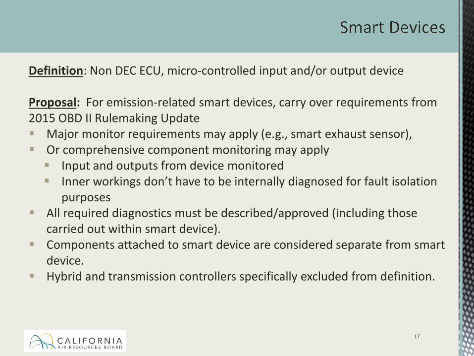
Definition: Non DEC ECU, micro-controlled input and/or output device
Proposal: For emission-related smart devices, carry over requirements from 2015 OBD II Rulemaking Update Major monitor requirements may apply (e.g., smart exhaust sensor), Or comprehensive component monitoring may apply Input and outputs from device monitored Inner workings don’t have to be internally diagnosed for fault isolation
purposes All required diagnostics must be described/approved (including those
carried out within smart device). Components attached to smart device are considered separate from smart
device. Hybrid and transmission controllers specifically excluded from definition.
17
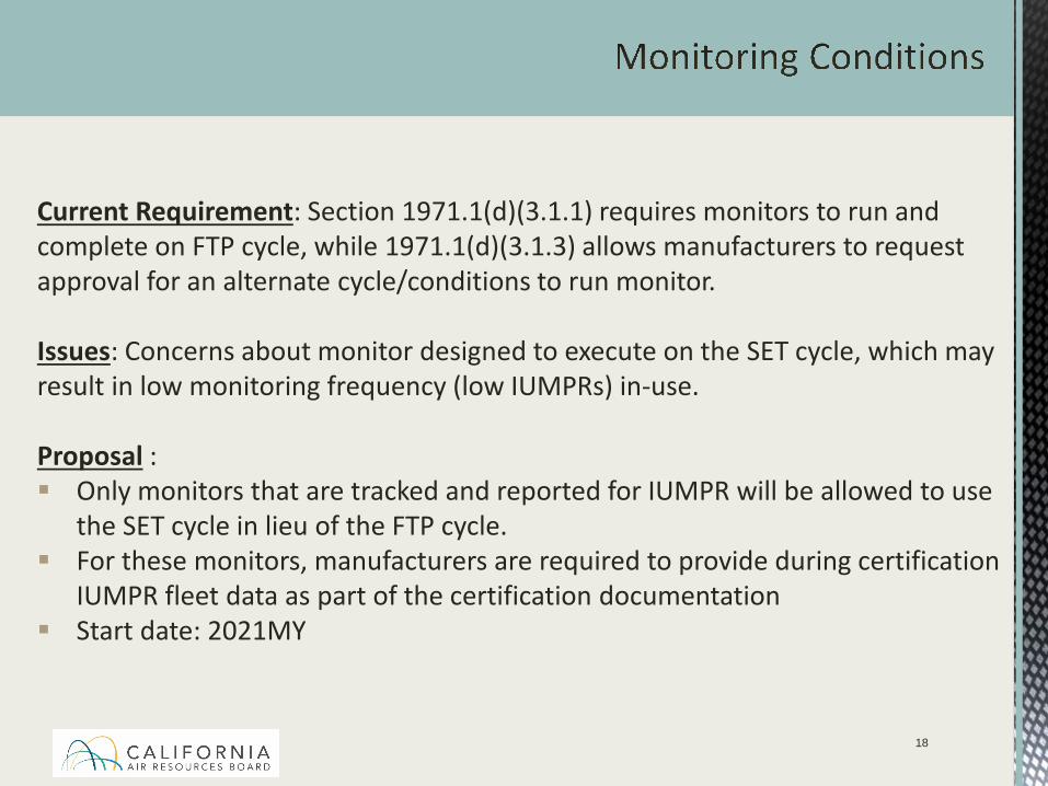
Current Requirement: Section 1971.1(d)(3.1.1) requires monitors to run and complete on FTP cycle, while 1971.1(d)(3.1.3) allows manufacturers to request approval for an alternate cycle/conditions to run monitor.
Issues: Concerns about monitor designed to execute on the SET cycle, which may result in low monitoring frequency (low IUMPRs) in-use.
Proposal : Only monitors that are tracked and reported for IUMPR will be allowed to use
the SET cycle in lieu of the FTP cycle. For these monitors, manufacturers are required to provide during certification
IUMPR fleet data as part of the certification documentation Start date: 2021MY
18
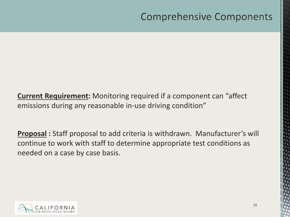
Current Requirement: Monitoring required if a component can “affect emissions during any reasonable in-use driving condition”
Proposal : Staff proposal to add criteria is withdrawn. Manufacturer’s will continue to work with staff to determine appropriate test conditions as needed on a case by case basis.
19
Highlights of Proposed Changes to HD OBD Regulations In-Use Monitoring Performance Ratio (IUMPR) Requirements Monitoring Requirements Durability Demonstration Engine (DDE) Testing Production Vehicle/Engine Evaluation Testing Standardization Requirements New data stream parameters NOx control performance tracking GHG-related parameters Certification Documentation Manufacturer Self-Testing Requirements
20
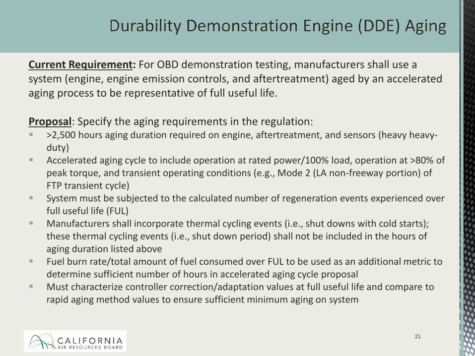
Current Requirement: For OBD demonstration testing, manufacturers shall use a system (engine, engine emission controls, and aftertreatment) aged by an accelerated aging process to be representative of full useful life.
Proposal: Specify the aging requirements in the regulation: >2,500 hours aging duration required on engine, aftertreatment, and sensors (heavy heavy-
duty) Accelerated aging cycle to include operation at rated power/100% load, operation at >80% of
peak torque, and transient operating conditions (e.g., Mode 2 (LA non-freeway portion) of FTP transient cycle)
System must be subjected to the calculated number of regeneration events experienced over full useful life (FUL)
Manufacturers shall incorporate thermal cycling events (i.e., shut downs with cold starts); these thermal cycling events (i.e., shut down period) shall not be included in the hours of aging duration listed above
Fuel burn rate/total amount of fuel consumed over FUL to be used as an additional metric to determine sufficient number of hours in accelerated aging cycle proposal
Must characterize controller correction/adaptation values at full useful life and compare to rapid aging method values to ensure sufficient minimum aging on system
21
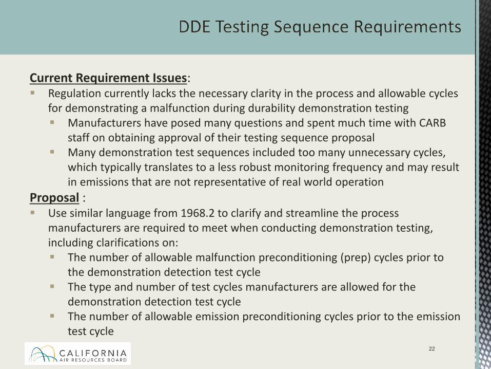
Current Requirement Issues: Regulation currently lacks the necessary clarity in the process and allowable cycles
for demonstrating a malfunction during durability demonstration testing Manufacturers have posed many questions and spent much time with CARB
staff on obtaining approval of their testing sequence proposal Many demonstration test sequences included too many unnecessary cycles,
which typically translates to a less robust monitoring frequency and may result in emissions that are not representative of real world operation
Proposal : Use similar language from 1968.2 to clarify and streamline the process
manufacturers are required to meet when conducting demonstration testing, including clarifications on: The number of allowable malfunction preconditioning (prep) cycles prior to
the demonstration detection test cycle The type and number of test cycles manufacturers are allowed for the
demonstration detection test cycle The number of allowable emission preconditioning cycles prior to the emission
test cycle22
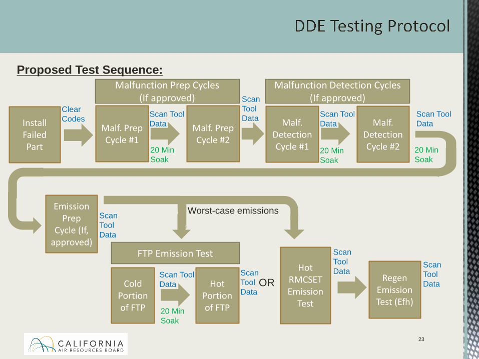
Proposed Test Sequence:
Clear Codes
Malfunction Prep Cycles (If approved)
Install Failed Part
Malf. Prep Cycle #1
Scan Tool Data
20 Min Soak
Malf. Prep Cycle #2
Emission Prep
Cycle (If, approved)
Hot RMCSET Emission
Test
Scan ToolData
Scan ToolData
Malfunction Detection Cycles (If approved)
Malf. Detection Cycle #1
Scan Tool Data Malf.
DetectionCycle #2
Scan Tool Data Scan Tool
Data
FTP Emission Test
Cold Portion of FTP
Scan Tool Data Hot
Portion of FTP
Scan Tool Data
20 Min Soak
Worst-case emissions
20 Min Soak
Regen Emission Test (Efh)
Scan ToolDataOR
23
20 Min Soak
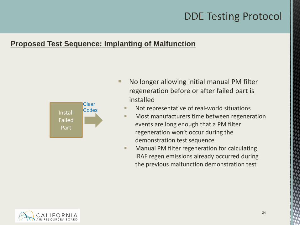
Proposed Test Sequence: Implanting of Malfunction
No longer allowing initial manual PM filter regeneration before or after failed part is installed Not representative of real-world situations Most manufacturers time between regeneration
events are long enough that a PM filter regeneration won’t occur during the demonstration test sequence
Manual PM filter regeneration for calculating IRAF regen emissions already occurred during the previous malfunction demonstration test
Clear CodesInstall
Failed Part
24
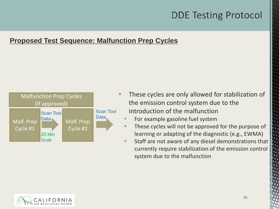
Proposed Test Sequence: Malfunction Prep Cycles
These cycles are only allowed for stabilization of the emission control system due to the introduction of the malfunction For example gasoline fuel system These cycles will not be approved for the purpose of
learning or adapting of the diagnostic (e.g., EWMA) Staff are not aware of any diesel demonstrations that
currently require stabilization of the emission control system due to the malfunction
Malfunction Prep Cycles (If approved)
Malf. Prep Cycle #1
Scan Tool Data Malf. Prep
Cycle #220 Min Soak
Scan Tool Data
25
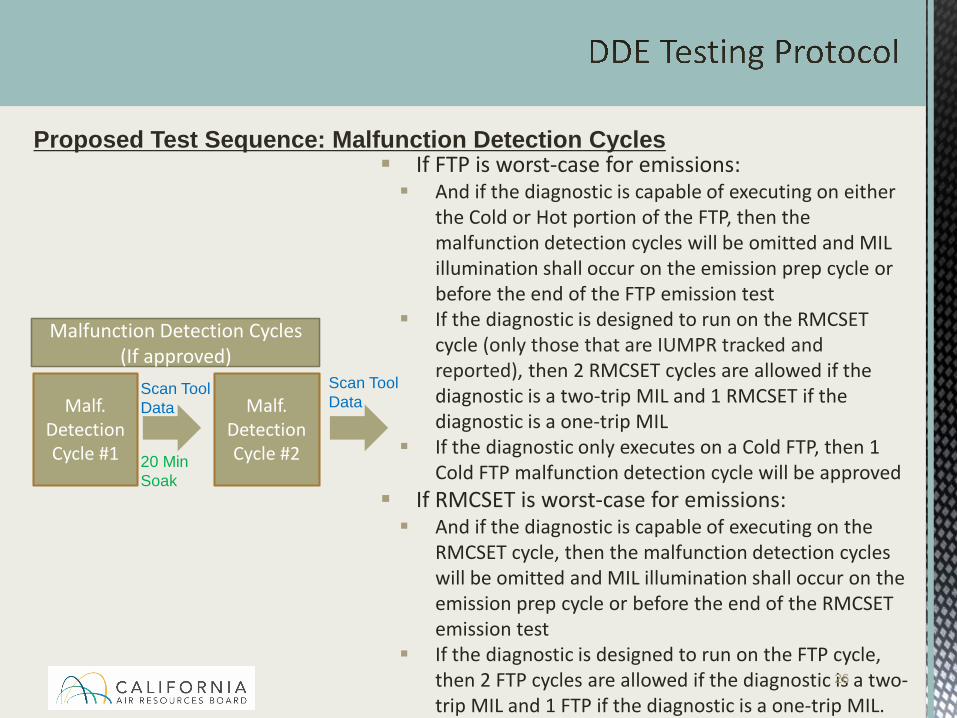
Proposed Test Sequence: Malfunction Detection Cycles If FTP is worst-case for emissions: And if the diagnostic is capable of executing on either
the Cold or Hot portion of the FTP, then the malfunction detection cycles will be omitted and MIL illumination shall occur on the emission prep cycle or before the end of the FTP emission test
If the diagnostic is designed to run on the RMCSET cycle (only those that are IUMPR tracked and reported), then 2 RMCSET cycles are allowed if the diagnostic is a two-trip MIL and 1 RMCSET if the diagnostic is a one-trip MIL
If the diagnostic only executes on a Cold FTP, then 1 Cold FTP malfunction detection cycle will be approved
If RMCSET is worst-case for emissions: And if the diagnostic is capable of executing on the
RMCSET cycle, then the malfunction detection cycles will be omitted and MIL illumination shall occur on the emission prep cycle or before the end of the RMCSET emission test
If the diagnostic is designed to run on the FTP cycle, then 2 FTP cycles are allowed if the diagnostic is a two-trip MIL and 1 FTP if the diagnostic is a one-trip MIL.
Malfunction Detection Cycles (If approved)
Malf. Detection Cycle #1
Scan Tool Data Malf.
DetectionCycle #220 Min
Soak
Scan Tool Data
26
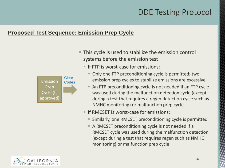
Proposed Test Sequence: Emission Prep Cycle
Clear CodesEmission
Prep Cycle (If,
approved)
This cycle is used to stabilize the emission control systems before the emission test If FTP is worst-case for emissions: Only one FTP preconditioning cycle is permitted; two
emission prep cycles to stabilize emissions are excessive. An FTP preconditioning cycle is not needed if an FTP cycle
was used during the malfunction detection cycle (except during a test that requires a regen detection cycle such as NMHC monitoring) or malfunction prep cycle
If RMCSET is worst-case for emissions: Similarly, one RMCSET preconditioning cycle is permitted A RMCSET preconditioning cycle is not needed if a
RMCSET cycle was used during the malfunction detection (except during a test that requires regen such as NMHC monitoring) or malfunction prep cycle
27
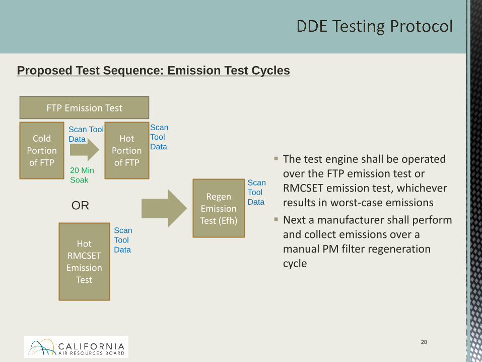
Proposed Test Sequence: Emission Test Cycles
The test engine shall be operated over the FTP emission test or RMCSET emission test, whichever results in worst-case emissions Next a manufacturer shall perform
and collect emissions over a manual PM filter regeneration cycle
Scan ToolData
FTP Emission Test
Cold Portion of FTP
Scan Tool Data Hot
Portion of FTP
Scan Tool Data
Regen Emission Test (Efh)
Hot RMCSET Emission
Test
Scan ToolData
20 Min Soak
OR
28
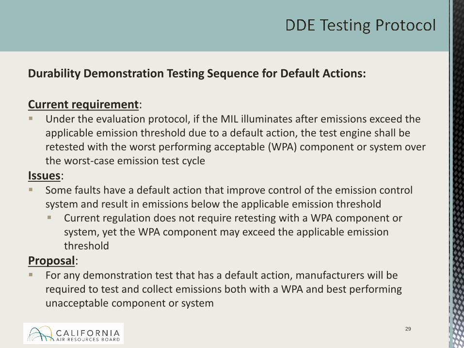
Durability Demonstration Testing Sequence for Default Actions:
Current requirement: Under the evaluation protocol, if the MIL illuminates after emissions exceed the
applicable emission threshold due to a default action, the test engine shall be retested with the worst performing acceptable (WPA) component or system over the worst-case emission test cycle
Issues: Some faults have a default action that improve control of the emission control
system and result in emissions below the applicable emission threshold Current regulation does not require retesting with a WPA component or
system, yet the WPA component may exceed the applicable emission threshold
Proposal: For any demonstration test that has a default action, manufacturers will be
required to test and collect emissions both with a WPA and best performing unacceptable component or system
29
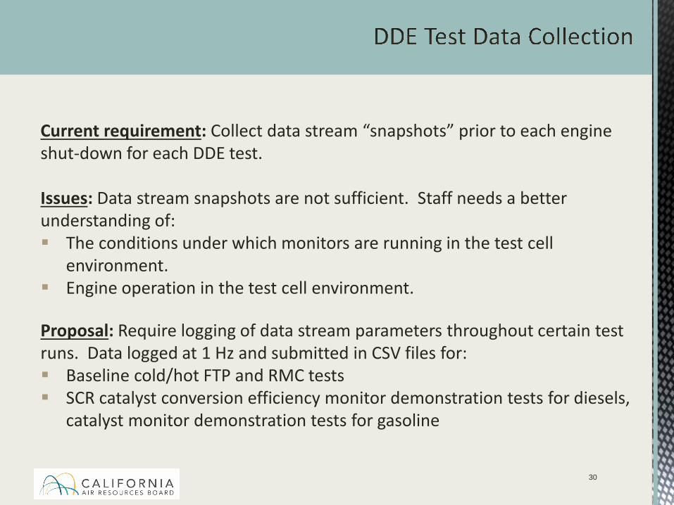
Current requirement: Collect data stream “snapshots” prior to each engine shut-down for each DDE test.
Issues: Data stream snapshots are not sufficient. Staff needs a better understanding of: The conditions under which monitors are running in the test cell
environment. Engine operation in the test cell environment.
Proposal: Require logging of data stream parameters throughout certain test runs. Data logged at 1 Hz and submitted in CSV files for: Baseline cold/hot FTP and RMC tests SCR catalyst conversion efficiency monitor demonstration tests for diesels,
catalyst monitor demonstration tests for gasoline
30
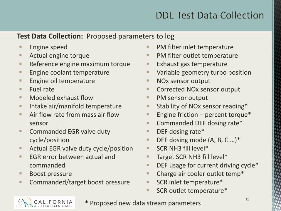
Engine speed Actual engine torque Reference engine maximum torque Engine coolant temperature Engine oil temperature Fuel rate Modeled exhaust flow Intake air/manifold temperature Air flow rate from mass air flow
sensor Commanded EGR valve duty
cycle/position Actual EGR valve duty cycle/position EGR error between actual and
commanded Boost pressure Commanded/target boost pressure
PM filter inlet temperature PM filter outlet temperature Exhaust gas temperature Variable geometry turbo position NOx sensor output Corrected NOx sensor output PM sensor output Stability of NOx sensor reading* Engine friction – percent torque* Commanded DEF dosing rate* DEF dosing rate* DEF dosing mode (A, B, C …)* SCR NH3 fill level* Target SCR NH3 fill level* DEF usage for current driving cycle* Charge air cooler outlet temp* SCR inlet temperature* SCR outlet temperature*
31
Test Data Collection: Proposed parameters to log
* Proposed new data stream parameters

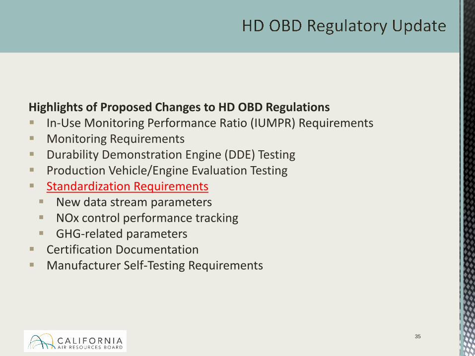
Highlights of Proposed Changes to HD OBD Regulations In-Use Monitoring Performance Ratio (IUMPR) Requirements Monitoring Requirements Durability Demonstration Engine (DDE) Testing Production Vehicle/Engine Evaluation Testing Standardization Requirements New data stream parameters NOx control performance tracking GHG-related parameters Certification Documentation Manufacturer Self-Testing Requirements
32
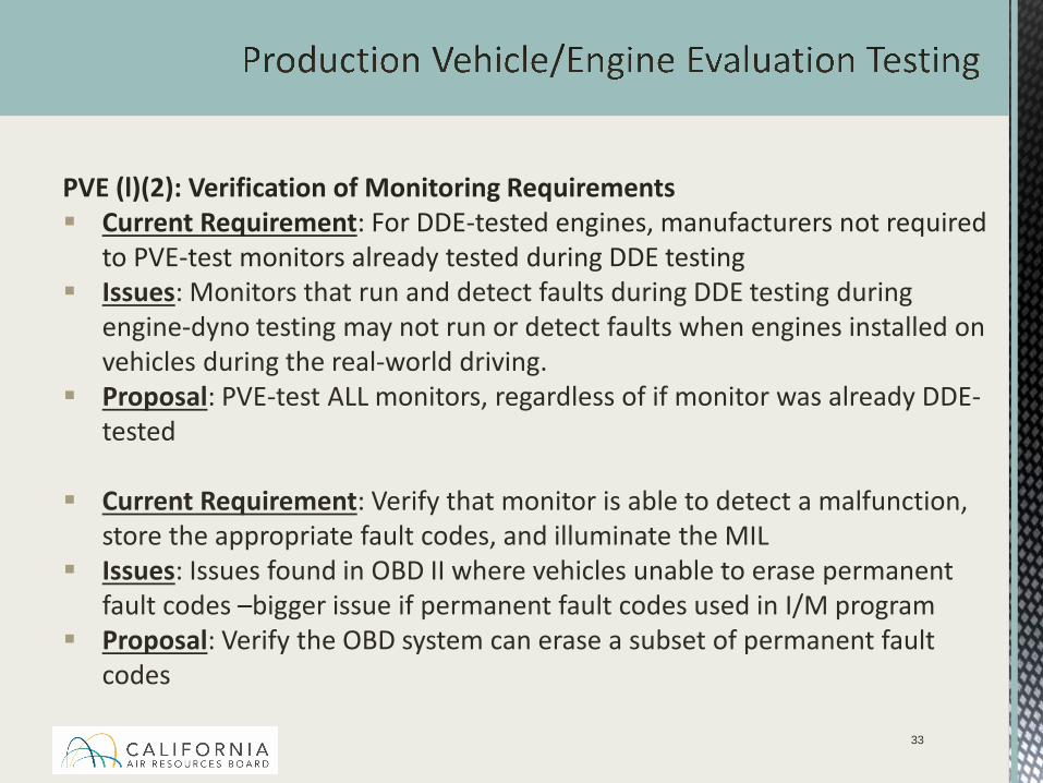
PVE (l)(2): Verification of Monitoring Requirements Current Requirement: For DDE-tested engines, manufacturers not required
to PVE-test monitors already tested during DDE testing Issues: Monitors that run and detect faults during DDE testing during
engine-dyno testing may not run or detect faults when engines installed on vehicles during the real-world driving.
Proposal: PVE-test ALL monitors, regardless of if monitor was already DDE-tested
Current Requirement: Verify that monitor is able to detect a malfunction, store the appropriate fault codes, and illuminate the MIL
Issues: Issues found in OBD II where vehicles unable to erase permanent fault codes –bigger issue if permanent fault codes used in I/M program
Proposal: Verify the OBD system can erase a subset of permanent fault codes
33
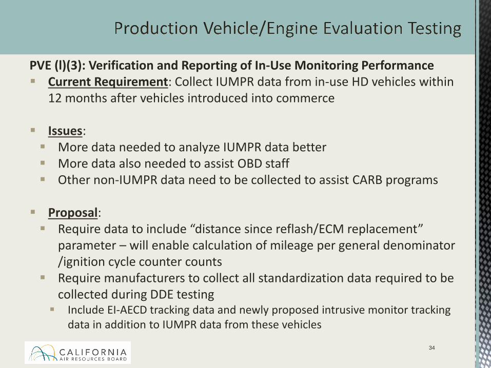
PVE (l)(3): Verification and Reporting of In-Use Monitoring Performance Current Requirement: Collect IUMPR data from in-use HD vehicles within
12 months after vehicles introduced into commerce
Issues: More data needed to analyze IUMPR data better More data also needed to assist OBD staff Other non-IUMPR data need to be collected to assist CARB programs
Proposal: Require data to include “distance since reflash/ECM replacement”
parameter – will enable calculation of mileage per general denominator /ignition cycle counter counts
Require manufacturers to collect all standardization data required to be collected during DDE testing Include EI-AECD tracking data and newly proposed intrusive monitor tracking
data in addition to IUMPR data from these vehicles
34
Highlights of Proposed Changes to HD OBD Regulations In-Use Monitoring Performance Ratio (IUMPR) Requirements Monitoring Requirements Durability Demonstration Engine (DDE) Testing Production Vehicle/Engine Evaluation Testing Standardization Requirements New data stream parameters NOx control performance tracking GHG-related parameters Certification Documentation Manufacturer Self-Testing Requirements
35
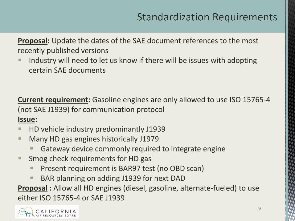
Proposal: Update the dates of the SAE document references to the most recently published versions Industry will need to let us know if there will be issues with adopting
certain SAE documents
Current requirement: Gasoline engines are only allowed to use ISO 15765-4 (not SAE J1939) for communication protocolIssue: HD vehicle industry predominantly J1939 Many HD gas engines historically J1979 Gateway device commonly required to integrate engine
Smog check requirements for HD gas Present requirement is BAR97 test (no OBD scan) BAR planning on adding J1939 for next DAD
Proposal : Allow all HD engines (diesel, gasoline, alternate-fueled) to use either ISO 15765-4 or SAE J1939
36
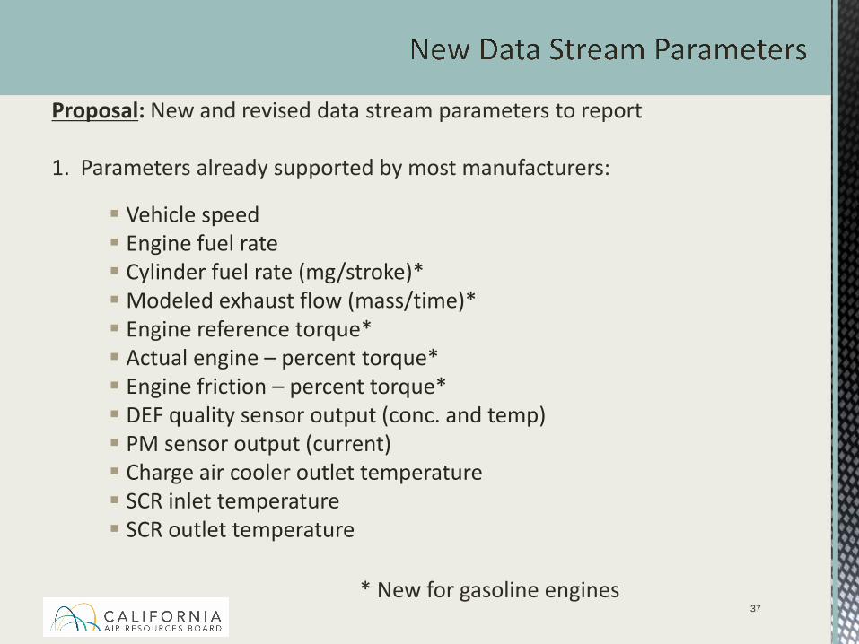
Vehicle speed Engine fuel rate Cylinder fuel rate (mg/stroke)* Modeled exhaust flow (mass/time)* Engine reference torque* Actual engine – percent torque* Engine friction – percent torque* DEF quality sensor output (conc. and temp) PM sensor output (current) Charge air cooler outlet temperature SCR inlet temperature SCR outlet temperature
37
Proposal: New and revised data stream parameters to report
1. Parameters already supported by most manufacturers:
* New for gasoline engines
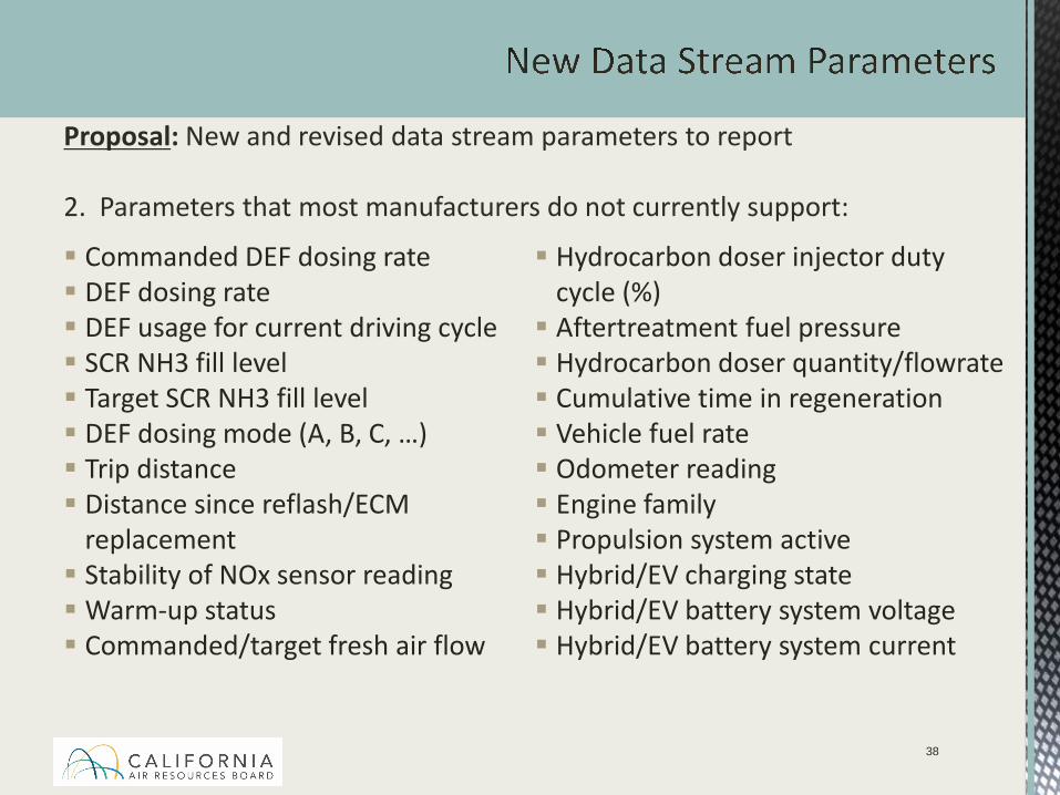
Commanded DEF dosing rate DEF dosing rate DEF usage for current driving cycle SCR NH3 fill level Target SCR NH3 fill level DEF dosing mode (A, B, C, …) Trip distance Distance since reflash/ECM
replacement Stability of NOx sensor readingWarm-up status Commanded/target fresh air flow
Hydrocarbon doser injector duty cycle (%) Aftertreatment fuel pressure Hydrocarbon doser quantity/flowrate Cumulative time in regeneration Vehicle fuel rate Odometer reading Engine family Propulsion system active Hybrid/EV charging state Hybrid/EV battery system voltage Hybrid/EV battery system current
38
Proposal: New and revised data stream parameters to report
2. Parameters that most manufacturers do not currently support:
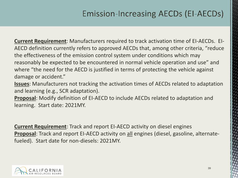
Current Requirement: Manufacturers required to track activation time of EI-AECDs. EI-AECD definition currently refers to approved AECDs that, among other criteria, “reduce the effectiveness of the emission control system under conditions which may reasonably be expected to be encountered in normal vehicle operation and use” and where “the need for the AECD is justified in terms of protecting the vehicle against damage or accident.”Issues: Manufacturers not tracking the activation times of AECDs related to adaptation and learning (e.g., SCR adaptation).Proposal: Modify definition of EI-AECD to include AECDs related to adaptation and learning. Start date: 2021MY.
Current Requirement: Track and report EI-AECD activity on diesel enginesProposal: Track and report EI-AECD activity on all engines (diesel, gasoline, alternate-fueled). Start date for non-diesels: 2021MY.
39
40
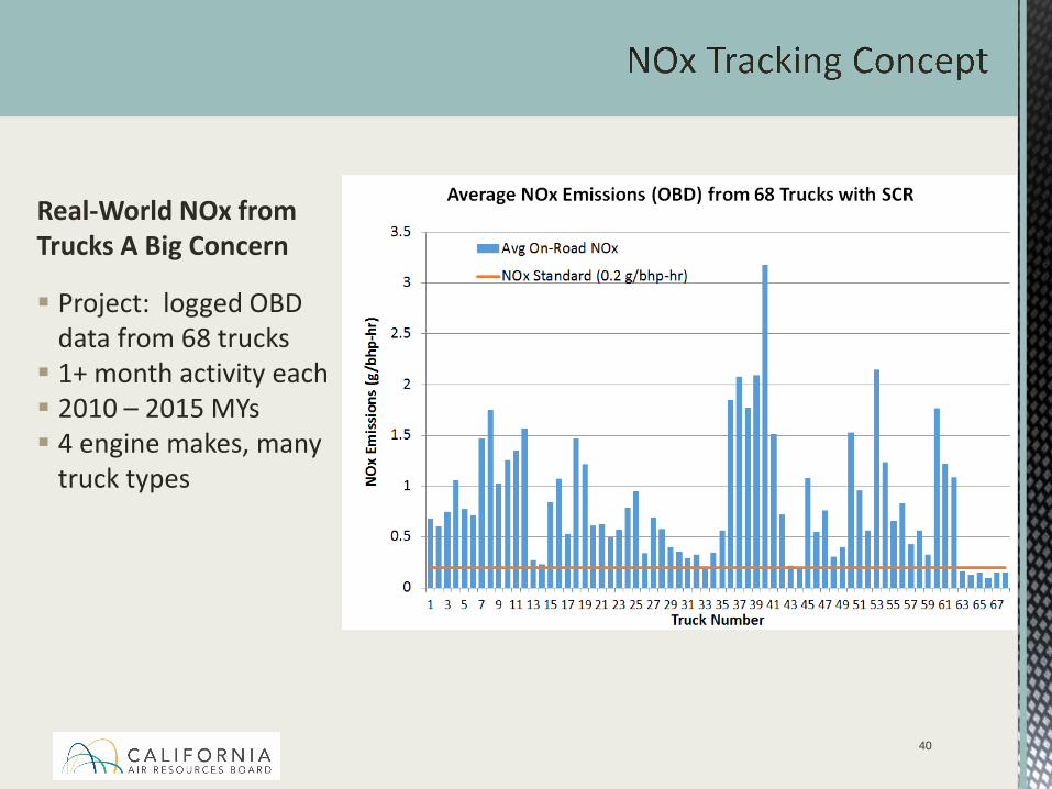
Project: logged OBD data from 68 trucks 1+ month activity each 2010 – 2015 MYs 4 engine makes, many
truck types
Real-World NOx from Trucks A Big Concern
41
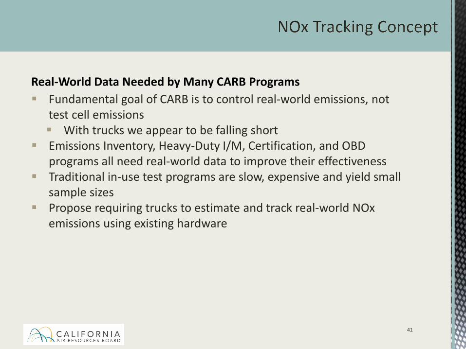
Real-World Data Needed by Many CARB Programs Fundamental goal of CARB is to control real-world emissions, not
test cell emissions With trucks we appear to be falling short
Emissions Inventory, Heavy-Duty I/M, Certification, and OBD programs all need real-world data to improve their effectiveness
Traditional in-use test programs are slow, expensive and yield small sample sizes
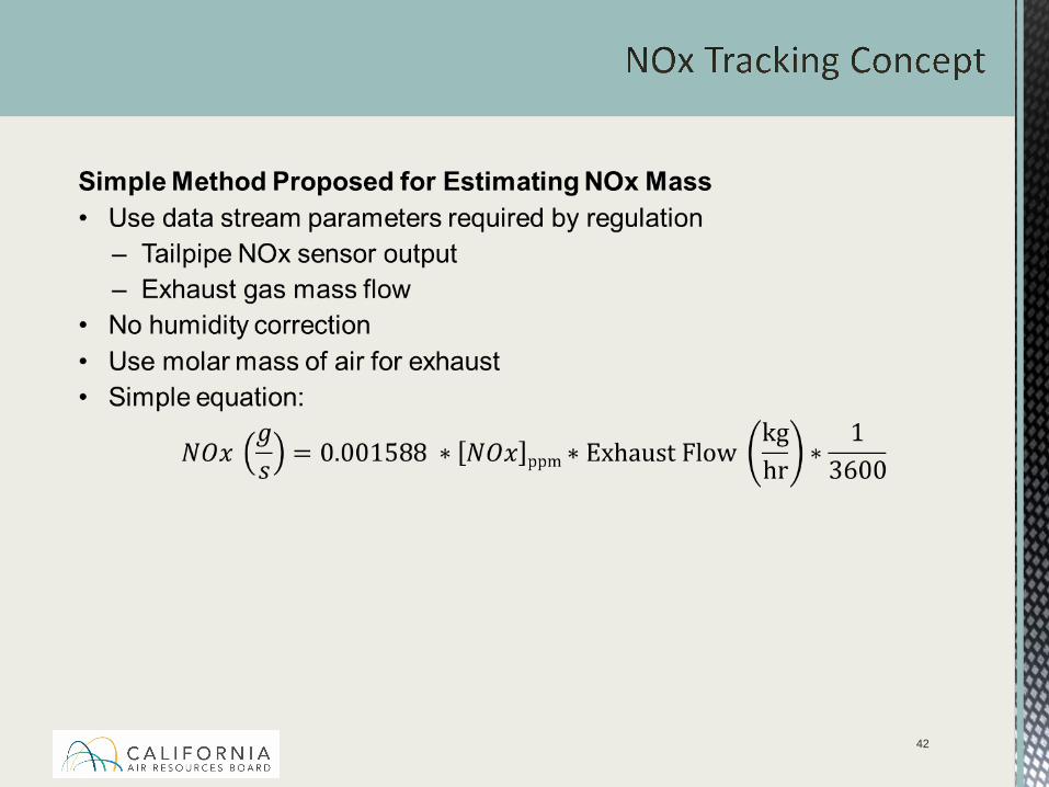
Propose requiring trucks to estimate and track real-world NOx emissions using existing hardware
42
43
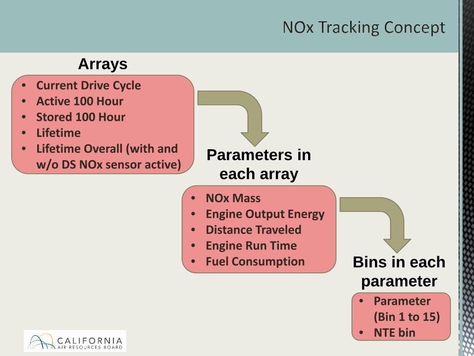
• Current Drive Cycle• Active 100 Hour• Stored 100 Hour• Lifetime• Lifetime Overall (with and
w/o DS NOx sensor active)
• NOx Mass• Engine Output Energy• Distance Traveled• Engine Run Time• Fuel Consumption
Arrays
Bins in each parameter• Parameter
(Bin 1 to 15)• NTE bin
Parameters in each array

44
% of Rated Power
Idle 1-10 10-25 25-40 40+
< 25 Bin 1 Bin 2 Bin 3 Bin 4 Bin 5
25 – 50 Bin 6 Bin 7 Bin 8 Bin 9 Bin 10
50+ Bin 11 Bin 12 Bin 13 Bin 14 Bin 15
Vehicle Speed (mph)
NTE Bin
Proposed Bin Structure
Parameter (Bin 1 – 15)
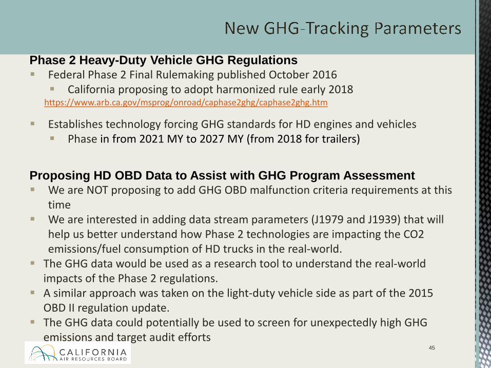
Phase 2 Heavy-Duty Vehicle GHG Regulations Federal Phase 2 Final Rulemaking published October 2016 California proposing to adopt harmonized rule early 2018
https://www.arb.ca.gov/msprog/onroad/caphase2ghg/caphase2ghg.htm
Establishes technology forcing GHG standards for HD engines and vehicles Phase in from 2021 MY to 2027 MY (from 2018 for trailers)
Proposing HD OBD Data to Assist with GHG Program Assessment We are NOT proposing to add GHG OBD malfunction criteria requirements at this
time We are interested in adding data stream parameters (J1979 and J1939) that will
help us better understand how Phase 2 technologies are impacting the CO2 emissions/fuel consumption of HD trucks in the real-world.
The GHG data would be used as a research tool to understand the real-world impacts of the Phase 2 regulations.
A similar approach was taken on the light-duty vehicle side as part of the 2015 OBD II regulation update.
The GHG data could potentially be used to screen for unexpectedly high GHG emissions and target audit efforts
45
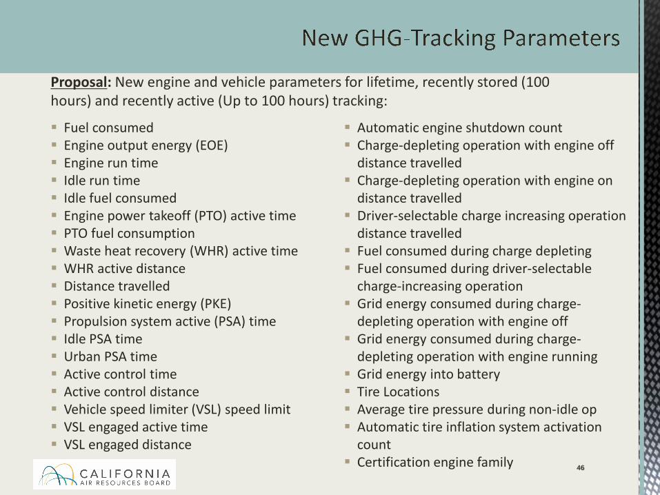
46
Fuel consumed Engine output energy (EOE) Engine run time Idle run time Idle fuel consumed Engine power takeoff (PTO) active time PTO fuel consumption Waste heat recovery (WHR) active time WHR active distance Distance travelled Positive kinetic energy (PKE) Propulsion system active (PSA) time Idle PSA time Urban PSA time Active control time Active control distance Vehicle speed limiter (VSL) speed limit VSL engaged active time VSL engaged distance
Automatic engine shutdown count Charge-depleting operation with engine off
distance travelled Charge-depleting operation with engine on
distance travelled Driver-selectable charge increasing operation
distance travelled Fuel consumed during charge depleting Fuel consumed during driver-selectable
charge-increasing operation Grid energy consumed during charge-
depleting operation with engine off Grid energy consumed during charge-
depleting operation with engine running Grid energy into battery Tire Locations Average tire pressure during non-idle op Automatic tire inflation system activation
count Certification engine family 46
Proposal: New engine and vehicle parameters for lifetime, recently stored (100 hours) and recently active (Up to 100 hours) tracking:
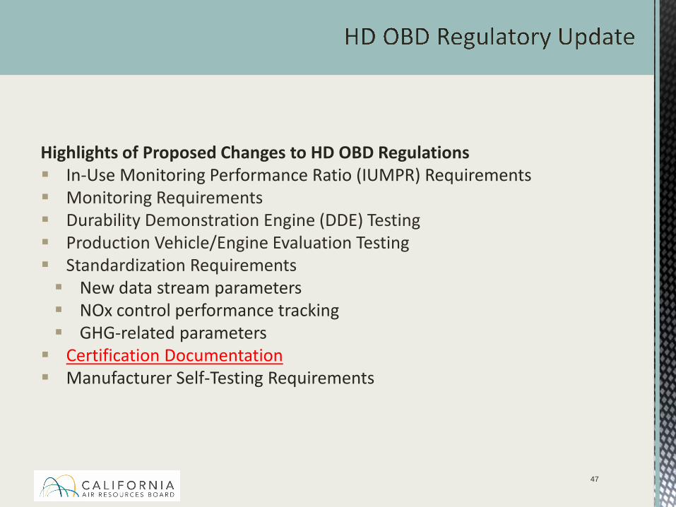
Highlights of Proposed Changes to HD OBD Regulations In-Use Monitoring Performance Ratio (IUMPR) Requirements Monitoring Requirements Durability Demonstration Engine (DDE) Testing Production Vehicle/Engine Evaluation Testing Standardization Requirements New data stream parameters NOx control performance tracking GHG-related parameters Certification Documentation Manufacturer Self-Testing Requirements
47
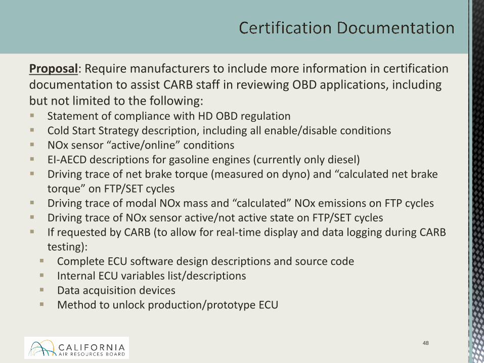
Proposal: Require manufacturers to include more information in certification documentation to assist CARB staff in reviewing OBD applications, including but not limited to the following: Statement of compliance with HD OBD regulation Cold Start Strategy description, including all enable/disable conditions NOx sensor “active/online” conditions EI-AECD descriptions for gasoline engines (currently only diesel) Driving trace of net brake torque (measured on dyno) and “calculated net brake
torque” on FTP/SET cycles Driving trace of modal NOx mass and “calculated” NOx emissions on FTP cycles Driving trace of NOx sensor active/not active state on FTP/SET cycles If requested by CARB (to allow for real-time display and data logging during CARB
testing): Complete ECU software design descriptions and source code Internal ECU variables list/descriptions Data acquisition devices Method to unlock production/prototype ECU
48
49
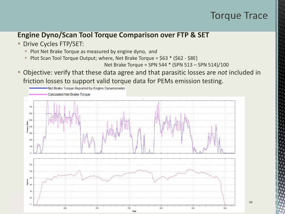
Engine Dyno/Scan Tool Torque Comparison over FTP & SET Drive Cycles FTP/SET: Plot Net Brake Torque as measured by engine dyno, and Plot Scan Tool Torque Output; where, Net Brake Torque = $63 * ($62 - $8E)
Net Brake Torque = SPN 544 * (SPN 513 – SPN 514)/100 Objective: verify that these data agree and that parasitic losses are not included in
friction losses to support valid torque data for PEMs emission testing.
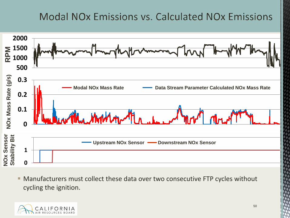
Manufacturers must collect these data over two consecutive FTP cycles without cycling the ignition.
50
500100015002000
0
0.1
0.2
0.3
0
1
2
RPM
NO
x M
ass
Rat
e (g
/s)
NO
x Se
nsor
Stab
ility
Bit
Upstream NOx Sensor Downstream NOx Sensor
Modal NOx Mass Rate Data Stream Parameter Calculated NOx Mass Rate
CARB staff still in discussion about which HD OBD amendments to also apply to medium-duty OBD II engines. May include following amendments: Additional IUMPR tracking and reporting requirements Modifications to feedgas monitoring test-out criteria New emission thresholds Additional standardization requirements (e.g., new data stream
parameters, NOx performance control tracking parameters)
51

Highlights of Proposed Changes to HD OBD Regulations In-Use Monitoring Performance Ratio (IUMPR) Requirements Monitoring Requirements Durability Demonstration Engine (DDE) Testing Production Vehicle/Engine Evaluation Testing Standardization Requirements New data stream parameters NOx control performance tracking GHG-related parameters Certification Documentation Manufacturer Self-Testing Requirements
52
Engine Procurement Expand mileage window from current 70-80% FUL requirement Increase maximum 80% to 100% FUL For engines with <70% FUL: Case-by-case basis: Manufacturers come in with plan for approval to
use engines (e.g., show equivalent results to 70% FUL). Plans could include: Increased submittal time to allow for more mileage accumulation Data showing hours to miles equivalency (to account for vocational
vehicles) Procuring lower mileage vehicle with additional OEM mileage
accumulation
53
Engine Procurement (cont.) Allow worst case re-rating of engine horsepower to match selected MST
engine Manufacturer to show if re-rating up or down is worst case Rerating only within a model year Engine being rerated needs to be identical to selected engine with
regard to hardware and emissions equipment Allow model year flexibility for procurement of direct carry-over engines
for additional engine testing (not used for initial MST engine) E.g., 2015 MY direct carry-over engine can be used for 2014 MY
additional engine testing (and vice versa) “Direct carry-over” to be defined (e.g., exact same calibration and
hardware carried over); no more than one model year separation CARB to choose additional engine from previous MY to meet next MY
additional engine test requirements; if applicable No more engines required to be procured if manufacturer agrees to
recall/fix problems found on initial engine(s)54
Testing Functional monitors – Testing may be conducted in a 1065-capable test
cell for first engine Verifying IRAFs - Manufacturer can carry over distance between
regenerations value, but still required to run the regeneration emissionstest
Invalid PM test results for monitors with no PM thresholds – no test over required
For manufacturers required to test engines from more than 1 engine rating (i.e., with >5 engine families for a given model year) - second engine testing may use 1065-capable test cell
55
40 CFR 1065 Capable Test Cell Proposal: Manufacturers required to test more than one test engine allowed to use an
alternative test procedure for all but one of the required test engines - this alternative test procedure can use a 1065 capable test cell. 1065 capable test cell - the same as a 1065 certified/compliant test cell with the
exception of calibration verification frequency: Monthly checks (35 days) increased to every 65 days 185 day checks increased to every 365 days/annually
Manufacturers assume a greater risk by going to longer time periods between QA checks/calibration verification checks. Important to bracket QA checks/calibration verification checks before and after
the given test period. If the manufacturer is unable to verify calibration of test cell equipment after
emissions testing, emissions testing must be rerun on a 1065 certified/compliant emission sampling system.
56
MST Monitors with Deficiencies
Issue: During MST, for monitors with a deficiency for exceeding the OBD limit (e.g., 0.450 g/bhp-hr vs 0.400 g/bhp-hr threshold), what emission result constitutes triggering procurement of additional engines?
Proposal: Still under consideration. Working with industry to determine a reasonable threshold above the emission result observed during the demonstration testing conducted prior to certification for which the deficiency was granted.
57
Official ARB documents available from www.arb.ca.gov
Direct link to OBD page: https://www.arb.ca.gov/msprog/obdprog/obdprog.htm
Leela Rao Manager, OBD Program Development SectionEmissions Compliance, Automotive Regulations and Science Division
[email protected](626) 350-6469
58


![Automotive Industry: Not Easy Being Green · friendly car. It produces 231 grams CO 2 emission per kilometer while EU standard is 120 CO 2 emission per kilometer [14]. e) Claim Vagueness](https://static.fdocuments.net/doc/165x107/602df0c0958ebd3ef5157156/automotive-industry-not-easy-being-green-friendly-car-it-produces-231-grams-co.jpg)