EmiEleveryspec.com/MIL-PRF/MIL-PRF-030000-79999/download.php?... · EmiEl MIL-PRF-62309C 6 March...
23
EmiEl MIL-PRF-62309C 6 March 1996 SUPERSEDING M3L-F-62309B(AT) 27 JSOUW 1986 PERFORMANCE SPECIFICATION FILTER ELEMENT, AIR This specification is approved for use by Departments and Agencies of the Department of Defense. 1. SCOPE 1.1 -. This specification establishes the performance, inspection, and acceptance requirements for an air tilter element used in the air induction system of the M60 series tank (see 6.1). 2. APPLICABLE DOCUMENTS 2.1 General. The documents listed in this section are specified in sections 3 and 4 of this specification. This section does not include documents in other sections of this specikation or recommended for addkional information or as examples. While every effort has been made to ensure the completeness of this list, document users are cautioned that they must meet all specified requirements documents cited in sections 3 and 4 of this specification, whether or not they are listed. Beneficial comments (recommendations, additions, deletions) and any pertinent data which may be of use in improving this document should be addressed to: U.S. Army Tank-automotive and Armaments Command, ATTN: AMSTA-TR-EIBLUE, Warre~ MI 48397-5000, by using the Standardization Document Improvement Proposal (I3D Form 1426) appearing at the end of this Idocument, or by letter. AMSC N/A FSC 2940 DISTRIBUTION STATEMENT A. Approved for public release; distribution is unlimited. Downloaded from http://www.everyspec.com
Transcript of EmiEleveryspec.com/MIL-PRF/MIL-PRF-030000-79999/download.php?... · EmiEl MIL-PRF-62309C 6 March...
EmiElMIL-PRF-62309C6 March 1996SUPERSEDINGM3L-F-62309B(AT)27 JSOUW 1986
PERFORMANCE SPECIFICATION
FILTER ELEMENT, AIR
This specification is approved for use by Departments andAgencies of the Department of Defense.
1. SCOPE
1.1 -. This specification establishes the performance, inspection, and acceptancerequirements for an air tilter element used in the air induction system of the M60 series tank(see 6.1).
2. APPLICABLE DOCUMENTS
2.1 General. The documents listed in this section are specified in sections 3 and 4 of thisspecification. This section does not include documents in other sections of this specikation orrecommended for addkional information or as examples. While every effort has been made toensure the completeness of this list, document users are cautioned that they must meet allspecified requirements documents cited in sections 3 and 4 of this specification, whether or notthey are listed.
Beneficial comments (recommendations, additions, deletions) and any pertinent data which maybe of use in improving this document should be addressed to: U.S. Army Tank-automotive andArmaments Command, ATTN: AMSTA-TR-EIBLUE, Warre~ MI 48397-5000, by using theStandardization Document Improvement Proposal (I3D Form 1426) appearing at the end of this
Idocument, or by letter.AMSC N/A FSC 2940DISTRIBUTION STATEMENT A. Approved for public release; distribution is unlimited.
Downloaded from http://www.everyspec.com
MIL-PRF-62309C
2.2 Government documents.
2.2.1 Specifications and standards. The following specifications, standards, andhandbooks form a part of this document to the extent specified herein. Unless otherwisespecified, the issues of these documents are those listed in the issue of the Department of DefenseIndex of Specifications and Standards (DoDISS) and supplement thereto, cited in the solicitation(see 6.2).
SPECIFICATIONS
FEDERAL
P-D-245 - Detergent, Laundry and Hand Dishwashing, (Granular).
STANDARDS
DEPART~NT OF DEFENSE
MIL-STD-810 - Environmental Test Methods and Engineering tildelines.
(lJrdess otherwise indicated, copies of the above specifications and standards are availablefrom the Standard~tion Document Order Desk, 700 Robbms Avenue, Building 4D, Philadelphi~PA 19111-5094.)
2,2.2 Other Government drawings. The following drawings form a part of this documentto the extent specified herein. Unless otherwise specified, the issues are those cited in thesolicitation.
DRAWINGS
10959032 - Efficiency and Dust Capacity Tester.10959082 - Master Box Assembly Gage.10959091 - Master Box Assembly Gage Ctilbration and Operating
Procedures,11669740 - Air Falter Element.12251922 - Air Cleaner Assembly - Steel.
(Copies of these drawings are available from the U.SArmaments Command, AMSTA-TR-E/J3LUE, Warreq Ml
Army Tank-automotive and48397-5000.)
2
Downloaded from http://www.everyspec.com
MIL-PRF-62309C
2.3 ‘Non-Government rmblications. The following documents forma part oftbisdocument to the extent specified herein. Unless otherwise specified, the issues of the documentswhich are DoD adopted are those listed in the issue of the DoDISS cited in the solicitation,Unless otherwise specified, the issues of documents not listed in the DoDISS are the issues of thedocuments cited in the solicitation (see 6.2).
AMERICAN SOCIETY FOR QUALITY CONTROL (ASQC)
ANSI/ASQC Z 1.4- %mpliig Procedures and Tables for Inspection by Attributes
(Application for copies should be addressed to American Society for Quality Control,611 East Wkconsin Avenue, Milwaukee, WI 53202-4606.)
AMERICAN SOCIETY FOR TESTING AND MATERIALS (ASTM)
AS~ C 800 - Standard Specification for Glass Fiber Blanket Insulation(Aircraft Type) (DoD Adopted).
ASTM D 774 - Standard Test Method for Bursting Strength of Paper(DoD Adopted).
ASTM D 828 - Standard Test Method for Tensile Properties of Paper andPaperboard, Using Constant-Rate-of-Elongation Apparatus@oD Adopted).
ASTM D 1149 - Standard Test Method for Rubber Deterioration - Surface OzoneCracking in a Chamber (DoD Adopted).
(Application for copies should be addressed to the American Society for Testing andMaterials, 100 Barr Harbor Drive, West Conshochocke~ PA 19428-2959.)
SOCIETY OF AUTOMOTIVE ENGINEERS (SAE)
SAE AS478 - Identification Marking Methods (DoD Adopted).
(Application for copies should be addressed to the Society of Automotive Engineers Inc.,400 Commonwealth Drive, Warrendale, PA 15096.)
TECHNICAL ASSOCIATION OF THE PULP AND PAPER INDUSTRY (TAPPI)
TAPPI T414 OM - Internal Tearing Resistance of Paper @mendorf-Type Method).
(Application for copies should be addressed to the Technical Association of the Pulp andPaper Industry, 15 Technology Parkway Soutk P.O. Box 105113, Norcross, GA 30092.)
3
Downloaded from http://www.everyspec.com
MIL-PRF-62309C
2.4 Order of precedence. In the event of a conflict between the text of this documentand the references cited herein, the text of this document takes precedence. Nothing in thisdocument, however, supersedes applicable laws and regulations unless a specific exemption hasbeen obtained.
3. REQUIREMENTS
3.1 Fist article. When specified (see 6.2), a sample shall be subjected to first articleinspection in accordance with 4.4 (see 6.3). First article inspection samples, properly marked withidentifying information shall be representative of the unit to be furnished to the Government. Allsubsequent air filter elements delivered to the Government shall conform to these samples in all oftheir pertinent physical and performance attributes.
3.2 Materials. Materials shall be uniform and free from imperfections or defects whichaffect their serviceabdity. All non-metrdlic materials shall be inherently finrgistatic or treated toresist fungus groWh. All metallic parts shall be made from corrosion resistant steels or treatedlplated with corrosion-resistant materials. Asbestos and cadmium matenrds shall not be used inany form in any part of the filter. No item, part or assembly shall contain radioactive materirds inwhich the specific activity is greater than 0.002 rnicrocurie per gram or activity per item equals orexceeds 0.01 rnicrocuries (see 4.6. 1).
3.2.1 Recycled. recovered. or enviromnentallv preferable materials. Recycled, recovered,or environmentally preferable materials should be used to the maximum extent possible providedthat the material meets or exceeds the operational and maintenance requirements, and promoteseconomically advantageous life cycle costs (see 4.6.1 and 6.5.3).
3.3 Design and construction. The air filter element, referred to herein as the element,shall be of the dry type for use as the second stage in a heavy duty two-stage air cleaner with a25485 liters per minute (IA@ [900 cubic foot per minute @3/rnin)] rating, and shall be inaccordance with Drawing 11669740 (see 4.6.2).
3.3.1 ~. The seal shall be properly seated and bonded in the seal retaining channelwith adhesive. The seal base surface shall be free of any release agent. No separation shall existbetween the seal body rmd the channel, and between channel and end cover. There shaUbe noexcessive adhesive buildup between the seal and the top edge of the channel walls (see 4.6.3).
3.3.1.1 Seal commission. The seal shall be capable of being compressed to the stops6.35 millimeters (mm) [0.25 inch (in)] over a 152.4 mm (6 in) section with a force of289 f89 Newton (N) [65 f 20 pounds (lb)] (see 4.6.4).
3.3.1.2 Seal adhesion. The serd shall be capable of withstanding a pull of 876 Newtonsper meter (N/m) [5 pound per inch (lb/in)] of length perpendicular to the surface (see 4.6.5).
4
Downloaded from http://www.everyspec.com
MIL-PRF-62309C
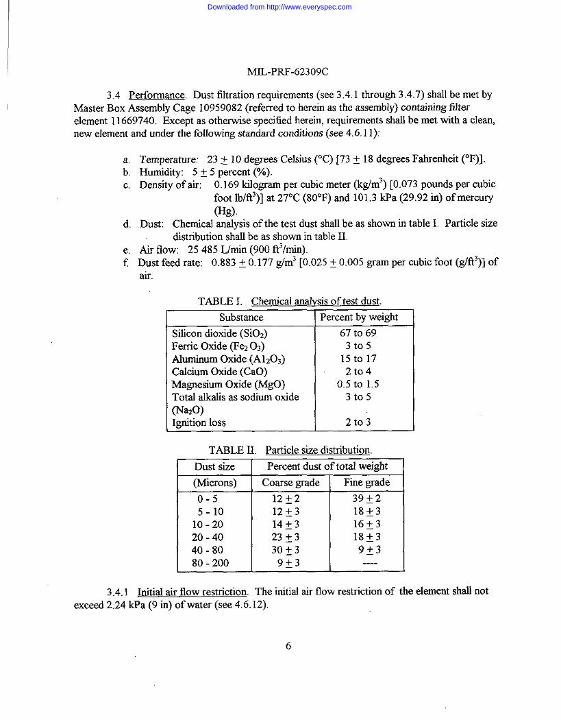
3.4 Performance. Dust filtration requirements (see 3.4.1 through 3.4.7) shall be met byMaster Box Assemblv Cage 10959082 (referred to herein as the assembly) containing filter.- .
element 11669740. Except as otherwise specified herein, requirements shall be met with a clean,new element and under the following standard conditions (see 4.6. 11):
:.
c.
d.
e.f
3.4.1
Temperature: 23 t 10 degrees Celsius C’C)[73 t 18 degrees Ftienheit 6F)I.Humidity: 5 f 5 percent (?’.).
Density of air: 0.169 kilogram per cubic meter (kg/m3) [0.073 pounds per cubicfoot lb/f13)]at 27°C (80”F) and 101.3 I@a (29.92 in) of mercury
@g).Dust: Chemical analysis of the test dust shall be as shown in table I. Particle size
distribution shall be as shown in table II.Air flow: 25485 L/rein (900 ft3/min).Dust feed rate: 0.883 t 0.177 ~m3 [0.025 i 0.005 gram Per cubic foot (M3)1 ofair.
TABLE I. Chemical analvsis of test dust.
Substance Percent by weight
Silicon dioxide (SiO,) 67 to 69Ferric Oxide (Fez 0s) 3t05Aluminum Oxide (A120,) 15to17Calcium Oxide (CaO) 2t04Magnesium Oxide (MgO) o,5to 1.5Total alkalk as sodium oxide 3t05(NatO)Igrition loss 2t03
TABLE IL Particle size dktnbution.
Dust size Percent dust of total weight
(Microns) Coarse grade Fme grade
o-5 1212 39*2
5-1o10-2020-4040-8080-200 d-
12f3 18~314f3 16~323f3 18~33of3 9*3
9~3 ----
Initial air flow restriction. The initial air flow restriction of the element shall notexceed 2.24kpa (9 in) of water (see 4.6.12).
Downloaded from http://www.everyspec.com
3.3.1.3 Seal ozone resistance.subjected to the tests of4.6.6.
MIL-PRF-62309C
The seal shall show no evidence of cracks or breaks, when
3.3.2 w. The element media shall be securely bonded to the element end caps withadhesive. The adhesive shall be free of porosity, voids, and pin hole leak paths (see 4.6.7).
3.3.2.1 Internal tear strength. The element media shall have a minimum internal tearresistance of 1000 grams (g) (see 4.6.7.1).
3.3.2.2 Burstirw stren~h. The element media shall have a minimum bursting strength of80 points (see 4.6.7.2 and 6.5.1).
3,3.2.3 Tensile breaking streruzth. The element media shall have a minimum tensilebreaking strength of 6895 kiloPascals (kPa) [1000 pound per square inch (lbtm’)] (see 4.6.7.3).
3.3.2.4 Flame resistance. The filtering media shall not continue to bum or smolder allerremoval of an applied flame (see 4.6.7.4).
3.3.3 Screen bonding and suPPorts. Protective mesh screens shrdlbe provided on theinside and outside of the element and shall be securely attached to the frame and bonded to theelement media. In additio~ structural channels shall be securely attached to the inside frame ofthe element and shall be bonded to the surface of the mesh screens in such a manner that flexureof the screens is mhimizd (see 4.6.8).
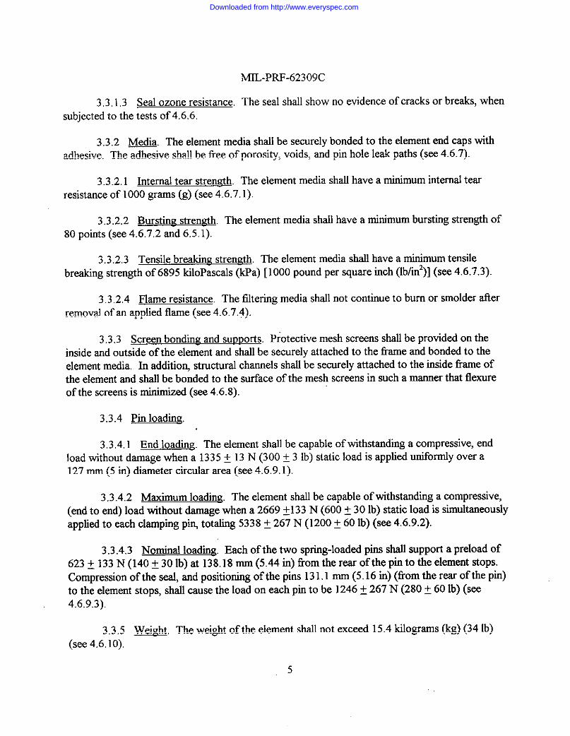
3.3.4 Pin Ioadlng.
3.3.4.1 End loading. The element shrdlbe capable of withstrmdkrg a compressive, endload Without damage when a 1335 f 13 N (300 f 3 lb) static load is appfied unifomrlYover a127 mm (5 in) diameter circular area (see 4.6.9.1).
3.3.4.2 ~. The element shall be capable of whhstandmg a compressive,(end to end) load without damage when a 2669 f133 N (600 t 30 lb) static load is simul~wxMIY
apphed to each clamp~g Pk tot~g 5338 t 267 N (1200 f 60 lb) (see 4.6.9.2).
3.3.4.3 Nominal Ioadmg. Each of the two spring-loaded pins shall support a preload of623 A 133 N (140 ~ 30 lb) at 138.18 mm (5.44 in) horn the rear of the pinto the element stops.Compression of the seal, and positioning of the pins 131.1 mm (5.16 in) (horn the rear of the pin)to the element stops, shall cause the load on each pinto be 1246 t 267 N (280 t 613lb) (see4.6.9.3).
3.3.5 -. The weight of the element shall not exceed 15.4 kilograms (kg) (34 lb)(see 4.6. 10).
5
Downloaded from http://www.everyspec.com
MIL-PRF-62309C
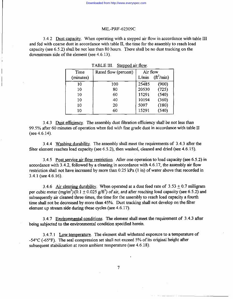
3.4.2 Dust cauacity. When operating with a stepped air flow in accordance with table IIIand fed with coarse dust in accordance with table II, the time for the assembly to reach loadcapacity (see 6.5 .2) shall be not less than 80 hours. There shall be no dust trachng on thedownst_rekn side of the element (see 4.6.13).
TABLE III. Stemred air flow.
Time(minutes)
101010101010
Rated flow (percent)
100806040
20
60
Air flowLhnirr @3/rnin)
25485 (900)20530 (725)15291 (540)10194 (360)5097 (180)15291 (540)
3.4.3 Dust efficiency. The assembly dust fdtration etliciency shall be not less than99.5% ailer 60 minutes of operation when fed with fine wade dust in accordance with table II(see 4,6.14).
3.4.4 Wasbirw durability. The assembly shall meet the requirements of 3.4.3 afrer thefilter element reaches load capacity (see 6.5.2), then washed, cleaned and dried (see 4.6. 15).
3.4.5 Post service air flow restriction. Atler one operation to load capacity (see 6.5.2) inaccordance with 3.4.2, foUowed by a cleaning in accordance with 4.6.17, the assembly air flowrestriction shall not have increased by more than 0.25 lcpa ( 1 in) of water above that recorded in3.4.1 (see 4.6.16).
3.4.6 Air cleanirrz durability. When operated at a dust feed rate of 3.53 f 0.7 rnilhgrrunper cubic meter (mg/m3) (0.1 f 0.025 g/f13)of air, and ailer reaching load capacity (see 6.5.2) andsubsequently air cleaned three times, the time for the assembly to reach load capacity a fourthtime shall not be decreased by more tharr 45~0. Dust tracking shall not develop on the filterelement up stream side during these cycles (see 4.6.17).
3.4.7 Environmental conditions. The element shall meet the requirement of 3.4.3 afterbeing subjected to the environmental condition specitied herein.
3.4.7.1 Low temperature. The element shall withstand exposure to a temperature of-54°C (-65°F). The serd compression set shall not exceed 5% of its original height atlersubsequent stabilization at room ambient temperature (see 4.6. 18).
‘7
Downloaded from http://www.everyspec.com
MIL-PRF-62309C
3.4.7,2 Hhzh temperature. The element shall withstand a high temperature of 71°C(+160”F). The seal compression set shall not exceed 25% of its original height after subsequentstabtiation at room ambient temperature (see 4.6.19).
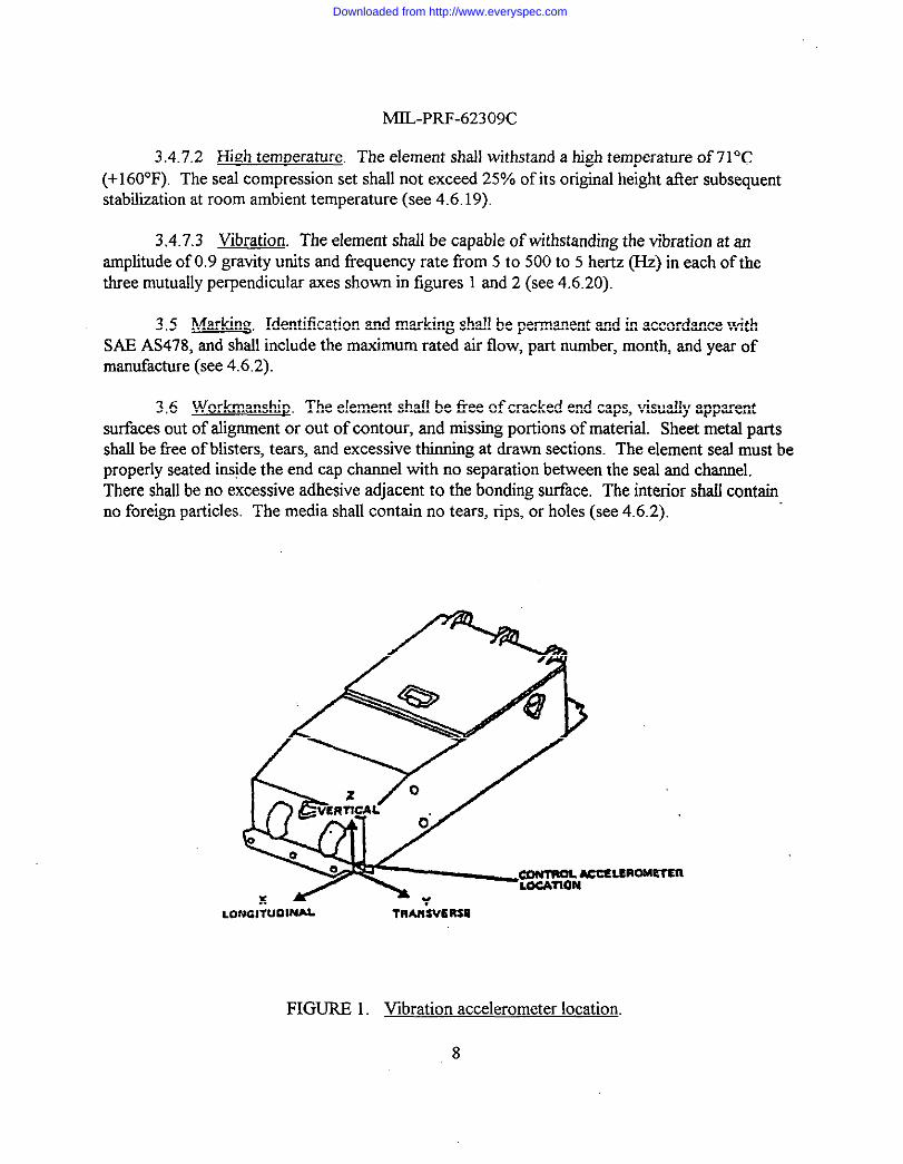
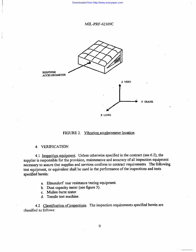
3,4.7.3 Vibration. The element shall be capable of withstanding the vibration at anamplitude of 0.9 gravity units and frequency rate ffom 5 to 500 to 5 hertz (Hz) in each of thethree mutually perpendicular axes shown in figures 1 and 2 (see 4.6.20).
3,5 Ma. Identification and marking shall be permanent and in accordance withSAE AS478, and shall include the maximum rated air flow, part number, month, and year ofmanufacture (see 4.6.2).
3,6 Workmanship The element shall be bee of cracked end caps, visually apparentsurfaces out of a.hgrrmentor out of contour, and missing portions of material. Sheet metal partsshall be bee of blisters, tears, and excessive thinning at drawn sections. The element seal must beproperly seated inside the end cap channel with no separation between the seal and channel.There shall be no excessive adhesive adjacent to the bonding surface. The interior shzdlcontainno foreign particles. The media shall contain no tears, rips, or ho!es (see 4.6.2).
LONGliUOl*
FIGURE 1.
TRAK”SV6RSM
Vibration accelerometer location.
8
Downloaded from http://www.everyspec.com
MIL-PRF-62309C
sESPONSE BACCKLSlto@~
z VERT.
.&
Y TrrANs.
X LONG.
FIGURE 2. Vibration accelerometer location.
4. VERIFICATION
4.1 ~spection eauipmea. Unless otherwise specfied in the contra~ (see 6.2), thesupplier is responsible for the provision, maintenance and accuracy of all inspection equipmentnecessary to assure that supplies and services conform to contract requirements. The followingtest equipment, or equivalent shall be used in the performance of the inspections and testsspecified hereim
a. Elrnendorf tear resistance testing equipment.b. Dust capacity tester (see figure 3).c. Mullen burst tester.d. Tensile test machine.
4.2 Classification of inspections. The inspection requirements specified herein areclassified as follows:
9
Downloaded from http://www.everyspec.com
MIL-PRF-62309C
a. Fkst article inspection (see 4.4).b. Conformance inspection (see 4.5).
1. Examination (see 4.5.2).2. Acceptance tests (see 4.5.3. 1),3. Control tests (see 4.5.3.2).
4.3 Inspection condkions. Unless otherwise specified (see 6.2), all inspections shall beperformed under the following condhions:
a. Air temperature: 23 t 10”C (73 f 18”F)b. Barometric pressure: 94.8 (+6.8, -10.2) kpa [28 (+2, -3) in] of Hgc. Relative humidity: 35 f 50/o
4.4 First article inspection. Unless otherwise specitied (see 6.2), the Government shallselect five elements from the first twenty produced under the production contract for first articleinspection. Fkst @icle samples shall be numbered and inspected as specitled in table IV.Approval of the first article sample by the Government shall not relieve the contractor of hisobligation to supply air filter elements that are filly representative of those inspected as a firstarticle sample. Any changes or deviation of the production units from the first article sample shallbe subject to the approval of the contracting officer.
4.4.1 First article inspection ftilure. Test item deficiencies during, or as a result of thefirst article test, shall be cause for rejection of the items until evidence has been provided by thecontractor that corrective action has been taken to eliminate the deficiency. Any deficiency foundduring, or as a result of the first article test, shall be prima facie evidence that all items alreadyproduced prior to completion of the first article test are similarly deficient unless evidencesatisfactory to the contracting officer is furnished by the contractor that they are not similarlydeficient. Such deficiencies on all items shall be corrected by the contractor at no cost to theGovernment. The Government shall not final accept products until first article testing iscompleted to the satisfaction of the Government.
4.5 Conformance inspection
4.5.1 Samuling
4,5.1.1 Lot formation. A lot shall consist of all air filter elements of one type, from anidentifiable production period, from one manufacturer, submitted at one time for conformanceinspection.
4.5.1.2 Samrrtirwfor examination. Samples for conformance examination shall beselected in accordance with general inspection level II of ANSI/ASQC Z 1.4.
10
Downloaded from http://www.everyspec.com
M3L-PRF-62309C
Thle
vlateriak>esign andconstruction>efects (seetablev)?eal$eal compressionSeal adhesionSeal ozoneresistanceMedia[nterrd tearresistanceBursting strengthTensile breakingstrengthFlame resistanceScreen bondingand SU3.rPOl’tS
Pin loading:End loadingMaximum loadingNominal loadingWeighthritial airtlowrestriction
Dust capacityDust efficiency
Washing durabfityPost service air-
flow restrictionAir cleaning
durabilityLow temperature
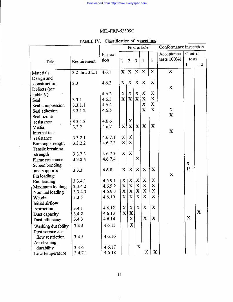
TABLE IV. Classification of inspectionsFkst article
requirement
.2 thru 3.2.1
.3
,3.1.3.1.1.3.1.2
.3.1.3
.3.2
.3.2.1i.3.2.2
i.3.2.31.3.2.4
1.3.3
!,3.4.1},3.4.21,3.4.3).3.5
).4.13.4.23.4.3
3.4.4
3.4.5
3.4.63.4.7.1
nspec-ion
1.6.1
1.6,2
!.6.2!.6.3t.6.4$.6.5
$.6.6t.6.7
$,6.7.1$.6.7.2
4.6.7.34.6.7.4
4.6.8
4.6,9.14.6.9.24.6,9.34.6.10
4.6.124.6.134.6.14
4.6.15
4,6.16
4.6.174.6.18
—
1
rx
x
x
x
x
x
x
x
x
x
x
x
x
x
x
x
>
—
)
T
K
KKx
K
K
x
x
x
x
x
x
x
>
onformance inspection
.cceptance:Sts 10070)
x
x
xx
x
x
L;ontroltests
2
x
11
Downloaded from http://www.everyspec.com
MIL-PRF-62309C
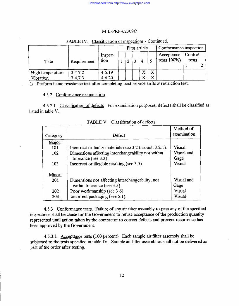
TABLE IV. Classification of inspections - Continued.
First article Conformance inspection
Inspec- Acceptance Control
Title Requirement tion 1 2 3 4 5 tests 10070) tests1 2
High temperature 3.4.’7.2 4,6.19 x xVibration 3.4.7,3 4,6.20 x x
l/ Perform flame resistance test after completing post service airflow restriction test.
4,5.2 Conformance examination.
4.5.2.1 Classification of defects. For examination purpcses, defects shall be classified aslisted in table V
Category
&101102
103
MinorT
202203
TABLE V. Classification of defects.
Defect
Incorrect or faulty materials (see 3.2 through 3.2.1).Dimensions afTectinginterchangeabdhy not within
tolerance (see 3.3).Incorrect or illegible marking (see 3.5).
Dimensions not affecting interchangeability, notwithin tolerance (see 3.3).
Poor workmanship (see 3 6).Incorrect packaging (see 5.1).
Method of~xamination
VisualvlSUd andGageVisual
vlSUd andGageVisualVlsud
4,5.3 Conformance tests. Failure of any air falter assembly to pass rmyof the specilledinspections shall be cause for the Government to refirse acceptance of the production quantityrepresented until action taken by the contractor to correct defects and prevent recurrence hasbeen approved by the Government.
4.5.3.1 Acceptance tests(100 rrercent). Each sample air tilter assembly shall besubjected to the tests specified in table IV. Sample air filter assemblies shall not be delivered aspart of the order tier testing.
12
Downloaded from http://www.everyspec.com
MIL-PRF-62309C
4.5.3.2 Control tests. Control tests shall be conducted on two air filter assemblies horneach 100 units consecutively produced, except that not more than one test shall be performed in athree month period, nor less than one test in a six mouth period. The air filter assemblies shall benumbered and subjected to the tests specified in table IV.
4.6 Methods of inspection.
4.6.1 Materials and construction. To determine confommnce to 3.2 through 3.2.1, airfilter element inspection and material certification records shall be maintained by the contractor.Records shall be subject to review by the Government and shall include date, part, orcharacteristic identification%inspection results, and deposition of lot (accepted or rejected).Corrective action taken on noted defects shall be subject to approval by the Government.
4.6.2 Defects. Conformance to 3.3 through 3.3.5 shall be determined by examination forthe defects listed in table V. Examination shall be visual, tactile, or by measurement with standardinspection equipment.
4.6.3 w. To determine conformance to 3.3.1, the seal shall be examined for properseating and bonding to the retaining channel. The retaining channel shall also be checked forproper sealiig to the end cover.
4.6.4 Seal compression. To determine conformance to 3.3.1.1, the element shall beimmoblliied and force shall be applied over a 152.4 mm (6 in) section until the seal is depressedto the stops or 567. of its free height. The force required shall be measured and verified that it isbetween 200 and 378 N (45 and 85 lb).
4.6.5 Seal adhesion. To determine conformance to 3.3.1.2, the following procedure shallbe performed: Make a transverse cut through the seal to the end cap with a sharp instrument.Attach a 25.4 mm ( l-in) clamp to one side of the cut seal, and measure the perpendicular forcerequired to pull the seal horn the end cap. Ver& that the seal does not detach itself ffom the endcap with a pull force of 876 N/m (5 lbhn) of length perpendicular to the surface.
4,6.6 Seal-ozone resistance. To determine conformance to 3.3.1.3, two or more testspecimens of the element gasket seal shall be subjected to the ozone resistance test in accordancewith ASTM D 1149 for accelerated ozone cracking of vulcanized rubber. The resistance testapparatus SW include an insulated test chamber with an ozone generating source outside thechamber. Means shall be provided for measuring the ozone concentratio~ for controlling thetemperature of the air in the chamber, and for circulating air. The apparatus shall also include ameans for holding and stretching the specimens. The procedure to be foUowed will permitspecimens to be elongated 12- l/2°/0. The stressed specimens, while still elongated in thestretching apparatus, shall be condhioned at room temperature for 45 minutes, and then shall be
13
Downloaded from http://www.everyspec.com
MJL-PRF-62309C
exposed for 72 hours in the test chamber in which air, having an ozone concentration of 45 to 55parts per 100,000,000 parts of air by volume, is circulated at a temperature of 35°C to 41°C(95°F to 105”F). Test specimens shall be examined frequently without magnification to determineconformance to 3.3.1.3.
4.6.7 -. To determine conformance to 3.3.2, element media bonding areas shall beexamined for secure bondhrg and the absence of porosity, voids, and leak paths.
4.6.7.1 Media internal tear resistance. To determine conformance to 3.3.2.1, elementmedia samples shall be tested for tear resistance in accordance with TAPPI T414 OM, usingElmendorftear testing equipment, or its equivalent.
4.6.7.2 Mdla bursting strength. To detemrine conformance to 3.3.2.2, element mediasamples shall be tested for bursting strength in accordance with ASTM D 774.
4.6.7.3 Media tensile breakirrzsh. To determine conformance to 3.3.2.3, elementmedia samples shall be tested for tensile strength in accordance with ASTM D 828. Thefollowing formula shall be used to calculate tensile strength:
Tensile strength (lb/in*)(kPa) = Breaking force (lb/in) (kticm2)Thickness (i) (cm)
4.6.7.4 Media flame resistarrce. To determine coirforrnarrce to 3.3.2.4, a sample of thetllter element me&a shall be exposed to a flame until the sample bums or glows. The flame shallthen be removed and the sample shall be observed.
4.6.8 Screen bonding and suDrIorts. To determine conformance to 3.3.3, the meshscreens for secure attachment to the frame and bonding to the media shall be examined asspecified in 3.3.3. Also, the structural supports for secure attachment to the frame and mirrimrdflexure of the mesh screens shall be examined as specified in 3.3.3.
4.6.9 Pin Ioadlng
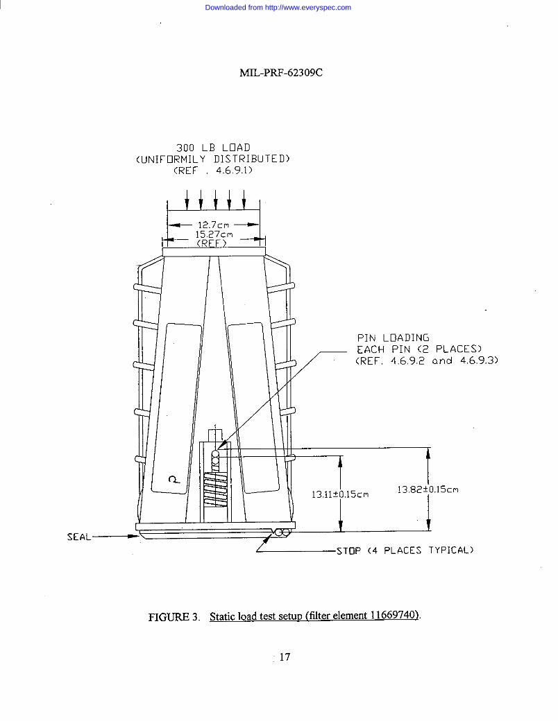
4.6.9.1 End loading. To determine cofiormance to 3.3.4.1. the element shall be placedon its mops in a device capable of measuring 1335 ~ 13 N (300 i 3 lb) load WKAY distributedover a 127 mm (5 in) diameter circular arq and applied to the element as shown in figure 3. Theelement shall be subjected to three successive non-overlapping static loads of 1335 t 13 N(300 f 3 lb). It shall be verified that no damage has resulted to the element.
4.6.9.2 Maximum loading, To determine conformance to 3.3.4.2, the element shall beplaced in a device capable of measuring two 2669 ~ 133 N (600 ~ 30 lb) loads simultaneouslyapplied to the element clamping pins as shown in figure 3, The element shall be subjected to a
14
Downloaded from http://www.everyspec.com
MIL-PRF-62309C
static load of 2669 N (600 lb) simultaneously applied to each clamping pin (total 5338 t 267 N)(total 1200 t 60 lb), until the seal is compressed to the stop. It shall be verified that no damagehas resulted to the element.
4.6.9.3 Nominal loading. To determine conformance to 3.3.4.3, the element shall bepositioned as in figure 3, and the following shall be performed with a force applied equally to eachpin:
a.
b.
c.
4.6.10
Apply force until a point on the rear of the pin reaches a position of138.2 fl.5 mm (5.44 t 0.06 in) from the element stops. Record the force, andveri@ that it is between 490 and 756N(110 and 170 lb).Apply additional force, until the point on the rear of the pin reaches a position of131.1 t 1.5 MM(5. 16 t 0.06 in) tlom the stops. Record the force, and verifi thatit is between 979 and 1512 N (220 and 340 lb).With a feeler gage, veri& that the seal is seated at all points about the perimeter ofthe seal
m. To determine conformance to 3.3.5, the element shall be weighed toveri$ that it does not exceed 15,4 kg (34 lb).
4.6.11 Fllterinszperformance. Except as otherwise specified herein, air filtrationperformance tests shall be performed on the element installed in Master Box Assembly Cage10959082; this installation is an instrumented fictional e@ivalent to Assembly 12251922.Except as otherwise specified herei~ test conditions and procedures shall be in accordance with3.4 and the following.
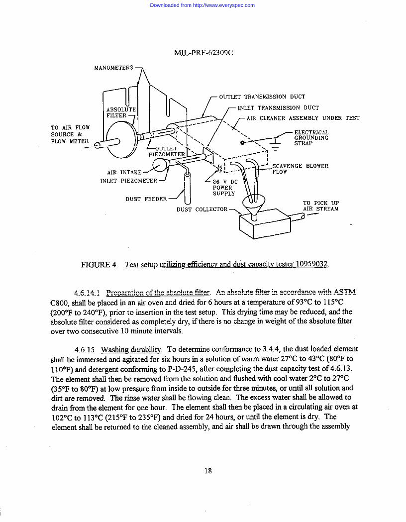
a.
b.
c.
d.
:
4.6.12
The test set-up for all tests requiring air tlow shall be conducted on an Efficiencyand Dust Capacity Tester 10959032 shown in figure 4.Dust feed rates shall be averaged over ten minute intervals. Measured airrestriction values shall be corrected to the specified air density to an accuracy of2,54 mm (O.1 in) of water.Actual air flow vahres used in tests shall be corrected to standard conditions(see 3.4c) and shall be within plus or minus two percent of specified values.The assembly shall be mounted in its normal operating attitude as shown infigure 1, and shall be electrically grounded.The scavenge air flow shrdlbe as speciiixl on Drawing 10959091.Air shall be drawn through the assembly with a turbine vacuum source to ensurefilter element dryness before starting tests.
Initial airflow restriction, To determine conformance to 3.4.1, the assembly shallbe subjected to a dust bee flow of 25485 Lhnin (900 ft3/rnirr)through the assembly. Therestriction to flow shall be measured, recorded, and shall not exceed 2.24 kpa (9 in) of water
15
Downloaded from http://www.everyspec.com
MIL-PRF-62309C
4.6.13 Dust capacity. To determine conformance to 3.4.2, an element shall be installedin the test setup of 4.6.11a, and one hour cycles with stepped flow rates shall be completed asspecified in table III. The restrictions to flow pressure drop through the assembly and absolutefilter shall be recorded each time the flow is adjusted to 25485 Lhnirr (900 f13hnin). The test shallbe conducted, until the assembly air flow restrictionat25485 Lhnirr reaches load capacity (see3.4). The operational time shall beat least 80 hours. At approximately twenty hour intervals ofcontinuous operation, or whenever the test setup is required to be shut down, the filter elementshall be viewed through the air cleaner outlet for visual signs of dust tracking on the clean side ofthe seal or the filter media. Any visual signs of dust tracking shall be cause for rejection.
4.6.14 Dust efficiency. To determine corrformance to 3.4.3, the element shall bemounted in the test setup of 4.6.11a with an absolute filter (see 4.6.14.1) at the output end of theassembly. Dust shall be placed in a dust feeder, and shall be fed into the input side of theassembly for 60 minutes with an airflow of 25485 L/tin. Restriction at the start of the test, andat 10 minute intervals throughout the test shall be recorded. The absolute titer shall be removedffom the test setup taking care not to disturb the entrapped dust, redried, and reweighed. Dustand absolute filter weighing shall be accurate to 0.01 gram (g). The efficiency of the assemblyshall be computed using the following formula:
Assembly Efficiency (’Yo)= W, - (W2 - W3)x 100
w,
Where: WI= Weight of dust fed into the assembly.W2 = Weight of absolute filter and its entrapped dust.Ws = Weight of absolute filter before test.
16
Downloaded from http://www.everyspec.com
MIL-PRF-62309C
300 LB LOAD(LINIFCiRMILY DISTRIBUTED)
(REF 4,6.9.1)
H+++l
mrlrl PIN LOADINGEACH PIN (2 PLACES)
Z (REF. 4692 and 4.6,9,3)
Iw Iu \ 131+C.13,82fj3.15cm
~STOP (4 PLACES TYPICAL)
FIGURE3. Static loadtest setup @lterelementl1669740)
17
Downloaded from http://www.everyspec.com
MIL-PRF-62309C
DERTO AIRSOURCEFLOW M
UPAM
TEST
FIGURE 4. Test setu~ utilizimz efficiency and dust capacity tester 10959032
4.6.14.1 Pre~aration of the absolute filter. An absolute filter in accordance with ASTMC800, shall be placed in an air oven and dried for 6 hours at a temperature of 93°C to 115°C(200”F to 240”F), prior to insertion in the test setup. This drying time may be reduced, and theabsolute filter considered as completely dry, if there is no change in weight of the absolute falterover hvo consecutive 10 minute intervals.
4.6.15Washhrz durability. To determine conformance to 3.4.4, the dust loaded elementshall be immersed and agitated for six hours in a solution of warm water 27°C to 43°C (80°F to110”F) and detergent conforming to P-D-245, after completing the dust capacity test of 4.6.13.The element shall then be removed tlom the solution and flushed with cool water 2°C to 27°C(35°F to 80”F) at low pressure from inside to outside for three minutes, or until all solution anddirt are removed. The rinse water shall be flowing clean. The excess water shall be allowed todrain from the element for one hour. The element shall then be placed in a circulating air oven at102”C to 113°C (215°F to 235”F) and dried for 24 hours, or until the element is dry. Theelement shall be returned to tbe cleaned assembly, and air shall be drawn through the assembly
18
Downloaded from http://www.everyspec.com
MIL-PRF-62309C
with a turbine vacuum source to ensure element drying. An optional filter drying method could beto install filter in air cleaner housing attached to an air source and draw air through filter until dry.The element shall then be subjected to the efficiency-test of 4.6.14 and shall conform to 3.4,3.
4.6.16 Post service airtlow restriction. To determine conformance to 3.4.5, after thedust capacity test to 4.6.13, the element shall be removed and cleaned of dust by using cleq dry,compressed air with 690 (+0, -69) I@a [100 (+0, -10) lbfinz] line pressure, and air nozzle imerdimension of at least 3.175 mm (1/8 inch). The air nozzle shall be inserted into the element, usinga back and forth motion along the length of each serration, and a duect flow into each pocketborn inside out. After the element is thoroughly air cleaned, it shall be reassembled in theassembly and tested for airtlow restriction. The assembly shall not exceed its previously recordedrestriction by more than 0.25 kpa (1 in) of water.
4,6.17 Air clearrirwdurability. To determine conformance to 3.4.6, the followingprocedure shall be performed: Install the filter element in the test setup of 4.6,1 la, and load it atthe dust feed rate of 3.53 t 0.7 mg/m3 (O.1 f 0.02g/fi3)until load capacity (see 6.5.2) is reached,and record the time. Prior to removal of the filter element &om the air cleaner, carefidly observethe clean side of the filter element for visual signs of dust tracking. Vkual observation will bemade through the air cleaner outlet. Any visual signs of dust tracking on the clean side of thefilter media or seal shall be cause for rejection. Air clean the filter element with cle~ dry,compressed air as specified in 4.6,16, until there is no visible evidence of dust being removed.Repeat the above procedure three times. The filter dust leading time shall not be decreased bymore than 450/0ailer third cleaning.
4.6.18 Low temperature. To determine conformance to 3.4.7.1, the element with theseal in compression to the element stops shall be subjected to a low temperature test as specifiedin I@L-STD-8 10, method 502.3, procedure 1. The condhions of 3.4.7.1 shall apply duringexposure to the low temperature. Seal height shall be measured to verify conformance to thecompression limit and to the dust efficiency test of 4.6.14.
4.6.19 High temrrerature. To determine conformance to 3.4.7.2, the element with theseal in compression to the element stops shall be subjected to a high temperature test as specifiedin MIL-STD-81O, method 501.3, procedure 1. The condhions of 3.4.7.2 shall apply duringexposure to the high temperature. S4 height sha.tlbe measured to ver@ conformance to thecompression limitand to the dust efficiency test of 4.6.14.
4.6.20 Vibration. To determine conformance to 3.4.7.3, the element shall be mounted inthe test setup of 4.6.11% and shall vibrate for a period of 80 minutes at specified amplitude andfkquency in each of three orthogonal axes. Connections and instrumentation shall be attached topermit testing as follows:
19
Downloaded from http://www.everyspec.com
MIL-PRF-62309C
a. The vibration test level shall be conducted at -40”C and 71“C (-40”F and +160”F).The time schedule shall be 80 minutes for each axis including forced dwells of13-1/3 minutes each (see figures 1 and 2).
b. Resonance search. Resonant tlequencies of the element shall be determined byvarying the frequency of applied vibration slowly through the specified range atreduced test levels, but with sufficient amplitude to excite the element. Sinusoidalresonance search may be performed using the test level and cycling time specifiedfor sinusoidal cycling test, provided the resonance search time is included in therequired cycliig test time.
c. Resonance dwell. The test element shall be vibrated along each axis at the mostsevere resonant frequencies. If more than four significant resonant tlequencies arefound for any one axis, the four most severe resonant frequencies shall be chosenfor the dwell test. If a change in the resonant frequency occurs during the test, itstime of occurrence shall be recorded and immediately the frequency shall beadjusted to maintain the peak resonance condition. The finrdresonant frequencyshall be recorded.
d. ARer vibration, the assembly shall be subjected to the efficiency test of 4.6.14 andshall be returned to room temperature and the element shall be examined for anydamage.
5. PACKAGING
5.1 ~. For acquisition purposes, the packaging requirements shall be asspecified in the contract or order (see 6.2). When actual packaging of materiel is to be performedby DoD persomel, these persomel need to contact the responsible packaging activity to ascertainrequisite packaging requirements. Packaging requirements are maintained by the InventoryControl Point’s packaging activity within the Military Department or Defense Agency, or withinthe Military Department’s System Command. Packaging data retrieval is available from themanaging Military Department’s or Defense Agency’s automated packaging files, CD-ROMproducts, or by contacting the responsible packaging activity.
6. NOTES
(This section mntains information of a general or explanatory nature which may behelptisl, but is not mandatory.)
6.1 Intended use. The filter element is intended specifically for use on Tank, Combat,Full-Tracked. M60 Series.
20
Downloaded from http://www.everyspec.com
MIL-PRF-62309C
6.2 Acquisitionrequirements.Acquisitiondocumentsmustspeci~thefollowing:
a. Thle, number, and date of this specification.b. Issue of DoDISS to be cited in the solicitation, and if required, the specific issue
of individual documents referenced (see 2.2 and 2.3).c. If first article is not required (see 3. 1).d. Part number of element required (see 3.4).e. If the responsibility for inspection equipment should be other than as specified
(see 4.1).f If inspection conditions should be other than as specified (see 4.3).g. If first article sample should be other than as specified (see 4.4).h. Packaging requirements (see 5. 1).
6.3 First article. First article samples should be tested and approved under theappropriate provisions of 7-104.55 of the Defense Acquisition Regulation. The contractingofficer should include specific instructions in all acquisition instruments regarding arrangementsfor examination, tests, and acquisition of the first article (see 3.1).
6.4 Subiect term (kev word) listing.
Dust capacityDust efficiencyDust filtrationFiltering instrumentM60 series trmk
6.5 Definitions
6.5.1 Bursting stremzth. The hydrostatic pressure, in pounds per square inch, required toproduce rupture of the material when the pressure is applied at a controlled increasing ratethrough a rubber diaphragm to a circular area 30.5 mm (1.200 in) in diameter, the area of thematerial under. test being initially flat and held rigidly at the circumference, but free to bulge underthe increasing pressure during test. To avoid mfision, this hydrostatic pressure is referred to as“points bursting strength.”
6,5.2 Load caDacity. The term used to indicate dust load has caused the air cleanerrestriction to reach 4.98 kpa (20 in) of water.
6.5.3 Recovered materials. “Recovered materials” means materials that have beencollected or recovered tlom solid waste (see 6.5 .4).
21
Downloaded from http://www.everyspec.com
MII-PRF-62309C
6.5.4 Solid waste. “Solid waste” is (a) any garbage, refuse, or sludge from a wastetreatment plant, water supply treatment plant, or air pollution control facility; and (b) otherdiscarded material, including solid, liquid, semisolid, or contained gaseous material resulting fromindustrial, commercial, mining, and agricultural operations, and from community activities. It doesnot include solid or dksolved materials in domestic sewage, or solid or dksolved material inirrigation return flows or industrial dkcharges which are point sources subject to permits undersections 402 of the Clean Water Act, (33 U. S.C. 1342 et seq.), or source, special nuclear, orbyproduct material as defined by the Atomic Energy Act of 1954042 U.S.C. 2011 et seq.)(Source: Federal Acquisition Regulations, section 23.402).
6.6 Charwes from mevious issue. Marginal notations are not used in this revision toidentifi changes with respect to the previous issue due to the extent of the changes.
Custodian:Army - AT
Review Activity:DLA - CS
Preparing Activity:Army - A’f
(Project 2940-0152)
22
Downloaded from http://www.everyspec.com
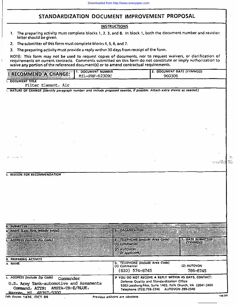
!I STANDARDIZATION DOCUMENT IMPROVEMENT PROPOSAL
1 ~TRUCTIONS
1.
2.
3.
The preparing activity must complete blocks 1, 2.3, and 8. In block 1, both the document number and revletter should be given.
The submitter of this form must complete blocks 4, 5,6, and 7.
The preparing activity must provide a reply wlthln 30 days from receipt of the form.
NOTE: This form may not be used to request copies of documents, nor to request waivers, or clari ficati orequirements on current contracts. Comments submitted cm this form do not constitute or imply authorizaticwaive any portion of the referenced document(s) or to amend contractual requirements.
““’*6’’’’::*::::: 1.DOCUMENT NUM6ERfrE&5mwENti?M&HmGP” ~~~_p~_&3~~R :.. .. ................. . . ...... .....
2. 00CUMENT OATE (Yt’MMCICI)~:;*.f*t,t<,:,::;:,T+:.:*2:x..,,..,,..3>:*,~..*,!*:,y,z::,;;,:,:,~,:,,!,;.:,:::;.,,.,,,;.:..:,?...,, 960306
1. 00CUMENT TITLEFilter Element, Air
i. NATURE OF CHANGE (Identifyparagraphnumb+rand includeproposedrewrite,if possible.Attach extra sheetsas needed.1
S.REASON FOR RECOMMENDATION
c.‘DDRESS~lnclude‘ip c@J Commander IFYOU 00 NOT RECEIVEA REPLYWITHIN45 OAYS,CONTACT:
U.S. Army Tank-automotive and Armaments OefenseQualityand StandardizationOffice
Ccxrmand, AT2N: MIST.A-TR-E/ELUE,5203LeesburgPike,Suite1403,FallsChurch,VA 22041-3466Telephone(703)756-234o AUTOVON 289-2340
cam-!-on MT Llr7%-r-mmnn FnmI fA>G. rEcT 89 Preview editmnsaw obsolete.
..-
Downloaded from http://www.everyspec.com